

Page 1
MOBILE ROLL FILE
TOOLS REQUIRED: Screwdriver
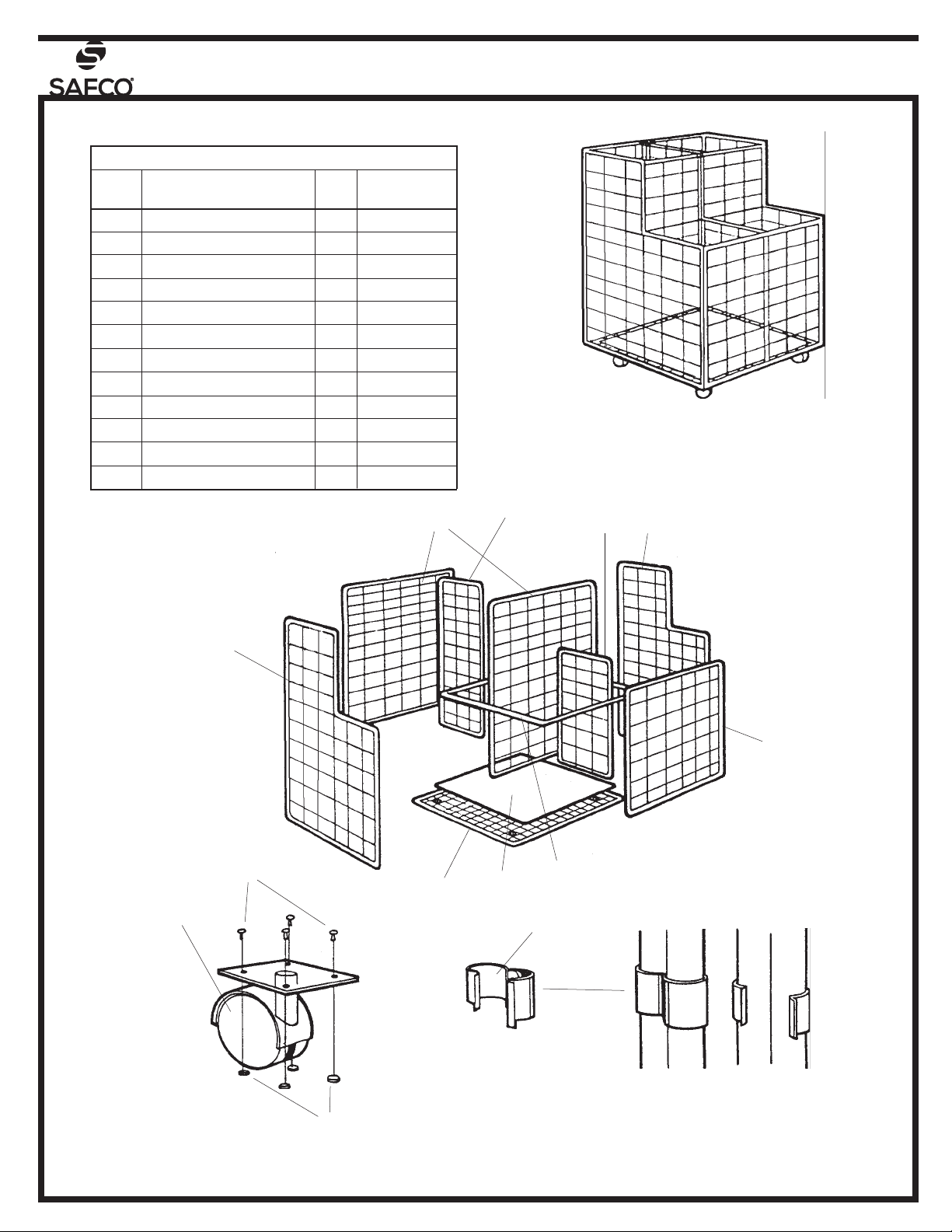
PARTS LIST
MODEL NUM-
BER
3084
LETTER
CODE
Caster 4 3084-08
Base Grid 1 3084-05
Screw 16 3084-13
Nut 16 3084-14
L-Shaped Grid 2 3084-09
Front Grid 1 3084-06
Large Grid 2 3084-02
Metal Clip 34 3084-11
Outer Support Bar 1 3084-07
Dust Guard 1 3084-12
Small Grid Divider 1 3084-04
Large Grid Divider 1 3084-03
DESCRIPTION QTY. PART NO.
A
B
C
D
E
F
G
H
I
J
K
L
ASSEMBLED UNIT
MODEL 3084
G
L
K
E
E
F
C
B
A
D
J
I
H
Metal Clips are used to join two grids as
shown above.
100308437: 1 of 3; Rev A; Rev Date 23-AUG-2016
Safco Products Company, New Hope, MN 55428
Page 2
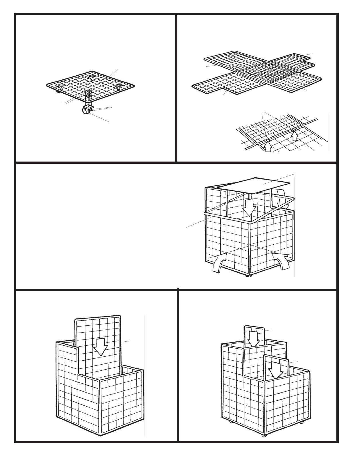
Install the four A Casters onto the pads of the B
12
Base Grid. Secure each caster with four C Screws
and four D Nuts.
Position the two E L-Shaped Grids, the F Front
Grid, and one of the G Large Grids around the base
grid as shown. Attach the grids to the base grid using two H Metal Clips per grid section.
E
B
C
Swing the face panel and one L-shaped panel up 90
3
degrees, and attach them together using two metal
clips, as before. Continue with the other grids until
all four sides are up. Place the I Outer Support Bar
over the unit, and attach it to the grid panels (at the
top of the lower level) with metal clips. Lay the J
Dust Guard inside the bottom of the unit.
D
A
G
F
E
H
AT EACH
CONNECTION, LOCATE
CLIPS APPROXIMATELY
WHERE INDICATED
J
I
Insert the remaining G Large Grid into the center of
4
the unit as shown, and secure with metal clips.
100308437: 2 of 3; Rev A; Rev Date 23-AUG-2016
Insert the K Small Grid Divider into the center of
5
the front opening as shown, and attach with metal
clips. Do the same with the L Large Grid Divider,
centered in the back opening.
L
G
K
Safco Products Company, New Hope, MN 55428
Page 3

CLASSEUR DE ROULEAUX MOBILE
OUTILS NÉCESSAIRES : Tournevis
LISTE DES PIÈCES
CODE
ALPHABÉ-
Roulette 4 3084-08
A
Grille de base 1 3084-05
B
Vis 16 3084-13
C
Écrou 16 3084-14
D
Grille en L 2 3084-09
E
Grille avant 1 3084-06
F
Grande grille 2 3084-02
G
Bride métallique 34 3084-11
H
Barre de soutien extérieure 1
I
J
Panneau pare-poussière 1
K
L
DESCRIPTION
QUAN-
No DE PIÈCE
3084-07
3084-12
NUMÉRO
DE MODÈLE
Installer les quatre roulettes A sur les patins de la grille de base
B . Attacher chaque roulette à l’aide de quatre vis C et de quatre
1
écrous D .
Positionner les deux grilles en L E , la grille avant F et l’une des
grandes grilles G autour de la grille de base, tel que l’indique
2
le dessin. Attacher les grilles à la grille de base en utilisant deux
brides métalliques H par section de grille.
Tourner vers le haut, sur un angle de 90 degrés, le panneau avant
et l’un des panneaux en L, et les attacher ensemble à l’aide de
3
deux brides métalliques, comme auparavant. Suivre la même
procédure avec les autres grilles jusqu’à ce que les quatre côtés
soient montés. Mettre la barre de soutien extérieure I sur l’unité,
puis l’attacher aux panneaux de grilles (à la partie supérieure du
niveau inférieur) à l’aide de brides métalliques. Mettre le panneau
pare-poussière J à l’intérieur du fond de l’unité.
Insérer la grande grille G qui reste dans le centre de l’unité, tel
que l’indique le dessin, puis l’attacher à l’aide de brides métal-
4
liques.
Insérer le séparateur K de la petite grille dans le centre de
l’ouverture avant, comme l’indique le dessin, puis l’attacher à
5
l’aide de brides métalliques. Suivre la même procédure avec
le séparateur L de la grande grille, le plaçant au milieu de
l’ouverture arrière.
3084
Metal clips are used to join two grids as shown above = Les brides métalliques servent à attacher deux grilles, comme l’indique le dessin.
À CHAQUE POINT D’ATTACHE, METTRE LES BRIDES À PEU PRÈS DANS LES ENDROITS INDIQUÉS
HERRAMIENTAS NECESARIAS: Un destornillador
LISTA DE PIEZAS
CLAVE ALFABÉTICA
Rueda 4 3084-08
A
Rejilla base 1 3084-05
B
Tornillo 16 3084-13
C
Tuerca 16 3084-14
D
Rejilla en L 2 3084-09
E
Rejilla del frente 1 3084-06
F
Rejilla grande 2 3084-02
G
Sujetador de metal 34 3084-11
H
Barra exterior de soporte 1
I
J
Placa antipolvo 1 3084-12
K
Rejilla de separación pequeña 1
L
DESCRIPCIÓN
ASSEMBLED UNIT MODEL 3084 = UNITÉ MONTÉE, MODÈLE 3084
AT EACH CONNECTION, LOCATE CLIPS APPROXIMATELY WHERE INDICATED =
PORTAPLANOS MÓVIL
Instale las cuatro ruedas, A , en las placas de la rejilla base,
1
B . Atornille cada rueda con cuatro tornillos, C , y cuatro
tuercas, D .
CANTI-
NO. DE PIEZA
3084-07
Coloque las dos rejillas en L, E , la rejilla del frente, F , y una
2
de las rejillas grandes, G , alrededor de la rejilla base, como
se muestra. Fije las rejillas a la rejilla base utilizando dos
sujetadores de metal, H , por cada sección.
Levante el panel del frente y uno en L a que queden verti-
3
cales. Únalos utilizando dos sujetadores de metal, como se
indicó anteriormente. Continúe con las otras rejillas hasta
que los cuatro costados estén verticales. Coloque la barra
exterior de soporte, I , en la unidad y fíjela a las rejillas (en
la parte superior del nivel más bajo) con los sujetadores
de metal. Coloque la placa antipolvo, J , en el fondo de la
unidad.
Inserte la rejilla grande, G , restante en el punto medio de
4
la unidad como se muestra, y fíjela con los sujetadores de
metal.
Inserte la rejilla de separación pequeña, K , en el punto
5
medio de la parte del frente como se muestra, y fíjela con los
separadores de metal. Haga lo mismo con la rejilla de separación grande, L , centrada en la parte de atrás de la unidad.
MODELO
NÚMERO
3084
Metal Clips are used to join two grids as shown above. = Los sujetadores de metal se usan para unir dos rejillas, como se muestra arriba.
EN CADA UNIÓN, COLOQUE LOS SUJETADORES APROXIMADAMENTE DONDE SE INDICA AQUÍ
100308437: 3 of 3; Rev A; Rev Date 23-AUG-2016
ASSEMBLED UNIT MODEL 3084 = UNIDAD ENSAMBLADA MODELO 3084
AT EACH CONNECTION, LOCATE CLIPS APPROXIMATELY WHERE INDICATED =
Safco Products Company, New Hope, MN 55428
 Loading...