

Page 1

an LDI Spaces Company
Minneapolis, MN 55428
www.safcoproducts.com
TOOLS REQUIRED: Phillips Screwdriver; Awl, or Hammer and Nail (Allen Wrench included)
PARTS LIST
CODE
A
B
C
D
E
F
G
H
J
K
L
M
N
O
P
DESCRIPTION
Slide Support 1 2175-01
Slider 1 2175-02
Upper Bracket 1 2175-03
Lower Bracket 1 2175-04
CPU Stop 1 2175-05
Hardware Pack 2175-19
Small Screw 10 2175-22
Large Bolt 4 2175-23
Socket Screw 4 2175-28
Handle 1 2175-10
I
Nut 1 2175-24
Washer 1 2175-31
Knob 1 2175-26
Spacer 1 2175-32
Round Pad 4 2175-12
Rectangular Pad 4 2175-13
Allen Wrench 1 2175-33
QTY.
Swivel-Mount CPU Holder
ASSEMBLY INSTRUCTIONS
Sort and count your parts before assembling!
PART NO.
G
H
A
2175
F
B
I
J
ASSEMBLED UNIT
MODEL 2175
PRODUCT WARRANTY CARD
is available online at: www.safcoproducts.
C
N
O
E
D
M
K
L
2175-37MP: 1 of 6;
12/05
available Monday-Friday 8:00 AM to 4:30 PM (Central Time) (English-speaking operators)
Safco Consumer Hot Line 1-800-664-0042
Page 2
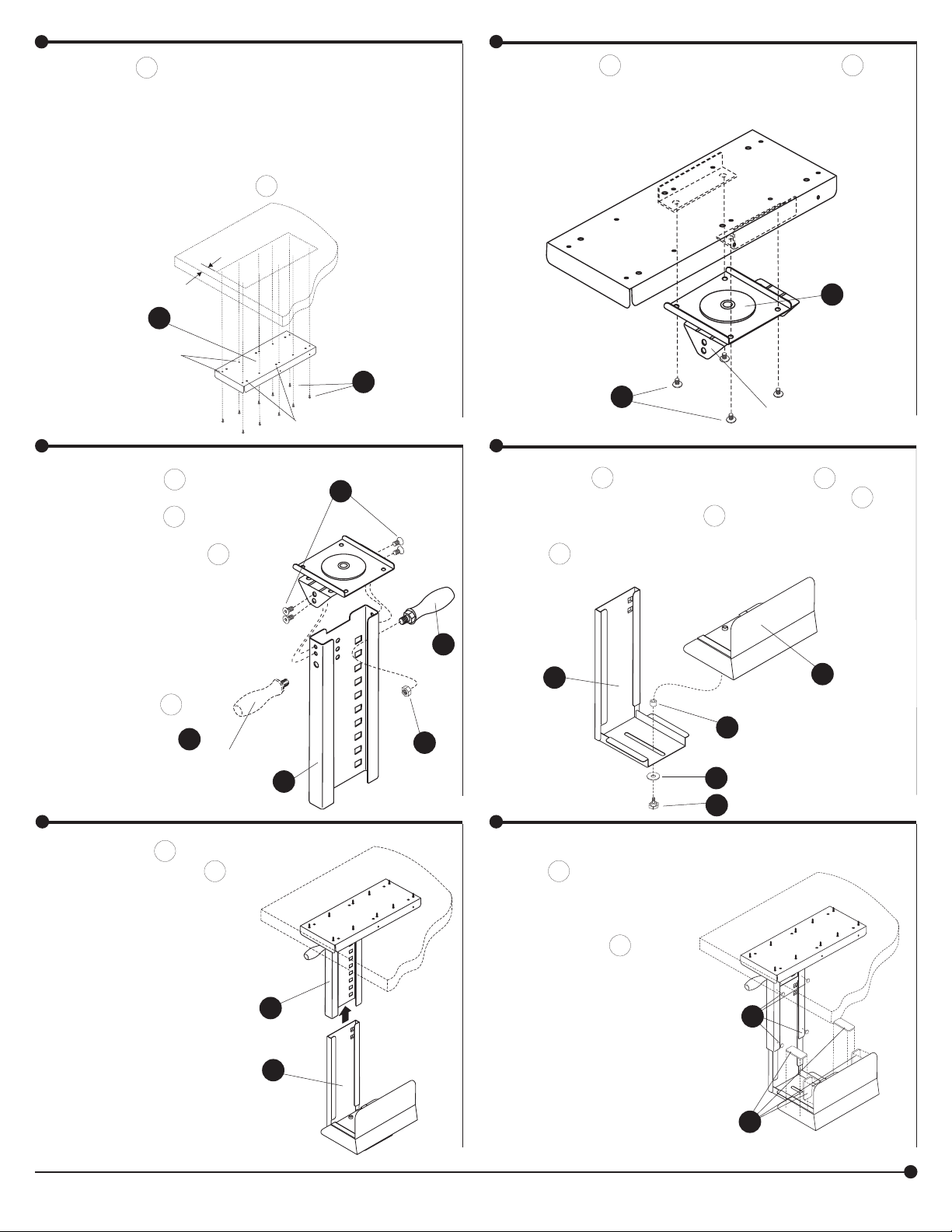
Fit the A Slide Support to the underside of your computer
1
work surface, keeping the front edge
about 5/8” back from the work surface edge and
with enough clearance at the sides to allow proper CPU
movement.
Mark the small hole positions with an awl or nail, and
mount securely with ten F Small Screws.
Using four G Large Bolts, securely fasten the B
2
Slider to the underside of the Slide Support (“L”
forward for left-side mounting; “R” forward for
right-side mounting).
5/8”
A
SMALL HOLES
Mount the C Upper
3
Bracket to the Slider
using four H Socket
Screws (left-side mounting shown). The I
Handle may be mounted on either side of the
Upper Bracket, depending upon which side
will face front. Mount
the Handle through the
large hole, using the J
Nut.
(ALTERNATE
POSITION)
B
F
LARGE
Place the K Washer onto the stem of the L Knob,
H
I
I
C
J
4
and insert the Knob stem through the slot in the D
Lower Bracket. Place the M Spacer onto the Knob
stem, and screw the Knob into the threaded hole on
the E CPU Stop. Leave the Knob loose enough
for the Stop to slide.
D
G
“L” OR “R”
E
M
K
L
Slide the D Lower
5
Bracket into the C
Upper Bracket to the
desired height. There
are seven positions available, at 1” spacings, to
adjust to CPU heights
from about 15” to 21”.
2175-37MP: 2 of 6; 12/05
Peel the backing from
6
the N Round Pads and
mount them to the Upper Bracket as shown.
Peel the backing from
the O Rectangular
Pads and mount them
to the CPU Stop as
C
D
shown.
Place the CPU into the
holder, slide the Stop
against the CPU, and
tighten the Knob.
Use the Handle to slide
the CPU in or out, or to
swivel it 180 degrees.
Safco Products Company, New Hope, MN 55428
N
O
Page 3

Support du pivot - mont pour l’Ordinateur
an LDI Company
New Hope, MN 55428
S’il vous plaît visiter-nous sur
l’Internet :
LISTE DES PIÈCES
CODE
Support pour le Glisseur 1 2175-01
A
Le glisseur 1 2175-02
B
Le Support supérieur 1 2175-03
C
Le Support inférieur 1 2175-04
D
Le rail de guidance de l’ordinateur 1 2175-05
E
Le petit Vis 10 2175-22
F
Le grand Verrou 4 2175-23
G
Le Vis du coulot 4 2175-28
H
Le manche 1 2175-10
I
L’écrou 1 2175-24
J
La rondelle 1 2175-31
K
Le bouton de l’ajustement 1 2175-26
L
L’entretoise 1 2175-32
M
Le coussinet rond 4 2175-12
N
Le coussinet rectangulaire 4 2175-13
O
La clef hexagonale 1 2175-33
P
DESCRIPTION
Paquet Matériel 2175-19
INSTRUCTIONS DE MONTAGE
LES OUTILS NÉCESSAIRES : Le Tournevis cruciforme (Phillips);
QTÉ.
L’alêne, ou Marteau et Clou (la clef hexagonale a inclus)
Triez et comptez les pièces !
O
DE PIÈCE
N
G
H
A
2175
F
B
I
J
ENSEMBLE MONTÉ
MODÈLE 2175
L’INSCRIPTION POUR LA GARANTIE DU PRODUIT
est disponible sur l’Internet : www.safcoproducts.com
C
N
O
E
D
M
K
L
2175-37MP: 3 of 6;
12/05
Pour toute question ou tout problème, veuillez communiquer avec l’Assistance téléphonique à la clientèle
Safco au 1-800-664-0042 du lundi au vendredi, de 8H00 à 16H30 (Heure centrale) (Opérateurs de langue anglaise)
Page 4

Arrangez le Support du Glisseur A sur le dessous de
1
votre surface du travail de l’ordinateur, garder le bord de
devant approximativement 1,59 cm (5/8 po) loin du bord
de la surface du travail et avec assez de jeu axial aux côtés
autoriser mouvement adéquat de l’Ordinateur.
Marquez les positions pour les petits trous avec une alêne
ou clouez, et attachez avec dix Petits Vis solidement F .
1,59 cm
(5/8 po)
A
LES PETITS
TROUS
LES TROUS DE
GROS DIAMÈTRE
F
Les utilisant quatre Grands Verrous G , solidement
2
attachez le Glisseur B au dessous du Support du
Glisseur (“L” vers l’avant pour monter du côté gauche;
“R” vers l’avant pour le support de droit-côté).
G
“L” OU “R”
B
Attachez le Support Supéri-
3
eur C au Glisseur qui utilise
quatre Vis du Coulot H (du
côté gauche montage montré). Le manche I peut
être installé sur l’un et l’autre
latéral du Support Supérieur.
Cela dépend sur que le côté
affrontera le devant.
Insérez le manche à travers
le trou de gros diamètre,
en utilisant l’Écrou J .
I
(POSITION
ALTERNATIVE)
Glissez le Support
5
Inférieur D dans le Support Supérieur C à la
hauteur désirée.
Il y a sept positions
disponible, dans 2,54
cms (1 po) augmentations, ajuster aux hauteurs de l’Ordinateur
d’approximativement
38,1 cms (15 po) à
53,34 cms (21 po).
Placez la Rondelle K sur la tige du Bouton L , et
H
J
C
C
D
4
insère la tige du Bouton à travers la rainure dans le
Support Inférieur D . Placez l’Entretoise M sur la
tige du Bouton, et visser le Bouton dans le trou fileté
sur le rail de guidance de l’Ordinateur E . Laissez le
Bouton détachez assez pour le rail de guidance pour
I
D
Pelez le papier du renforcement
6
des Coussinets Ronds N et les
attache au Support Supérieur
comme montré. Pelez le papier
du renforcement des Coussinets
Rectangulaires
O et les attache au rail de guidance de l’Ordinateur comme
montré.
Placez l’Ordinateur dans le support, glissez le rail de guidance
contre l’Ordinateur,
et serrez le Bouton de
l’Ajustement.
Utilisez le manche pour glisser
l’Ordinateur dans ou dehors,
ou le pivoter 180 degrés.
M
K
L
N
O
E
2175-37MP: 4 of 6; 12/05
Safco Products Company, New Hope, MN 55428
Page 5

an LDI Company
New Hope, MN 55428
Por favor visítenos en la Internet:
www.safcoproducts.com
LAS HERRAMIENTAS NECESARIAS: El Destornillador de Phillips;
La lezna, o Martillo y punta de París (el tirón hexagonal incluyó)
LISTA DES PIEZAS
CODIGO
El apoyo para el deslizador 1 2175-01
A
El deslizador 1 2175-02
B
El Anaquel superior 1 2175-03
C
El más bajo Anaquel 1 2175-04
D
El rail guía de la computadora 1 2175-05
E
El Tornillo pequeño 10 2175-22
F
El Perno grande 4 2175-23
G
El Tornillo de la enchufe-cabeza 4 2175-28
H
La palanca de tiro 1 2175-10
I
La tuerca 1 2175-24
J
La arandela 1 2175-31
K
El bulto de ajuste 1 2175-26
L
El espaciador 1 2175-32
M
La Almohadilla redonda 4 2175-12
N
La Almohadilla rectangular 4 2175-13
O
El tirón hexagonal 1 2175-33
P
DESCRIPTION
Paquete Materiel 2175-19
CANT.
El Apoyo girando para la Computadora
INSTRUCTIONS DE MONTAGE
¡Organice y cuente las piezas!
NO. DE
G
H
A
B
I
J
2175
F
UNIDAD ENSAMBLADA
DE MODELO 2175
El REGISTRO PARA LA GARANTÍA DEL PRODUCTO
está disponible en la Internet: www.safcoproducts.com
C
N
O
E
D
M
K
L
2175-37MP: 5 of 6;
12/05
Para dudas o preguntas, favor de llamar a Línea directa para el cliente de Safco 1-800-664-0042
Disponible lunes-viernes de 8:00 AM a 4:30 PM (Hora Central) (Operadores que hablan inglés)
Page 6

Coloque el Apoyo del Deslizador A hacia la parte inferior de
1
su superfi cie de trabajo de computadora, guardando el borde
delantero aproximadamente 1.59 cm (5/8 “) fuera del borde de
superfi cie de trabajo y con bastante juego libre axial a los lados
para permitir movimiento apropiado de la Computadora.
Marque las posiciones para los huecitos con una lezna o punta
de París, y ate fi rmemente con diez Tornillos Pequeños F .
1.59 cm
(5/8 “)
A
LOS HUECITOS
F
LAS PERFORACIONES
ANCHA
Use cuatro Pernos Grandes G para atar el deslizador
2
firmemente B a la parte inferior del Apoyo del deslizador
(“L” delantero para del lado izquierdo montar; “R” delantero
para el montaje del derecho-lado).
G
“L” O “R”
B
Ate la abrazadera de
3
montaje Superior C al
Deslizador que usa cuatro
Tornillos de la Enchufe-cabeza H (del lado izquierdo
el montar demostrado).
Instale la palanca de tiro
I en un lado o el otro de
la abrazadera de montaje
Superior. Esto depende
en que el lado enfrentará el frente. Inserte la
palanca de tiro a través
de la perforación
ancha, ate con la
Tuerca J .
I
(LA POSICIÓN
ALTERNADA)
Resbale la Más bajo abrazade-
5
ra de montaje D en la abrazadera de montaje Superior C a
la altura deseada. Hay siete
posiciones disponible,
en 2.54 cm (1 “) los incrementos, para ajustar
a las alturas de la Computadora de aproximadamente
38.1 cms (15 “) a
53.34 cms (21 “).
Ponga la Arandela K hacia el tallo del bulto de ajuste
H
4
L , e inserta el tallo de bulto de ajuste a través de la ranura
de ajuste en la Más bajo abrazadera de montaje D .
Ponga el Espaciador M hacia el tallo de bulto de ajuste, y
atornilla el bulto de ajuste en el agujero fileteado en el rail
guía de la Computadora E . Deje el bulto de ajuste suelte
bastante para el rail guía resbalar.
I
D
E
M
J
C
K
L
Pele el papel de apoyo de
6
las Almohadillas Redondas
N y los ata a la abrazadera
de montaje Superior como
mostrado. Pele el papel de
apoyo de las Almohadillas
Rectangulares O y los
ata al rail guía de la Computadora como mostrado.
C
D
Ponga la Computadora en
el apoyo, resbale el rail guía
contra la Computadora, y
aprete el bulto de ajuste.
Use la palanca de tiro para
resbalar la Computadora en
o fuera, o para girarlo 180
grados.
N
O
2175-37MP: 6 of 6; 12/05
Safco Products Company, New Hope, MN 55428
 Loading...