

Page 1
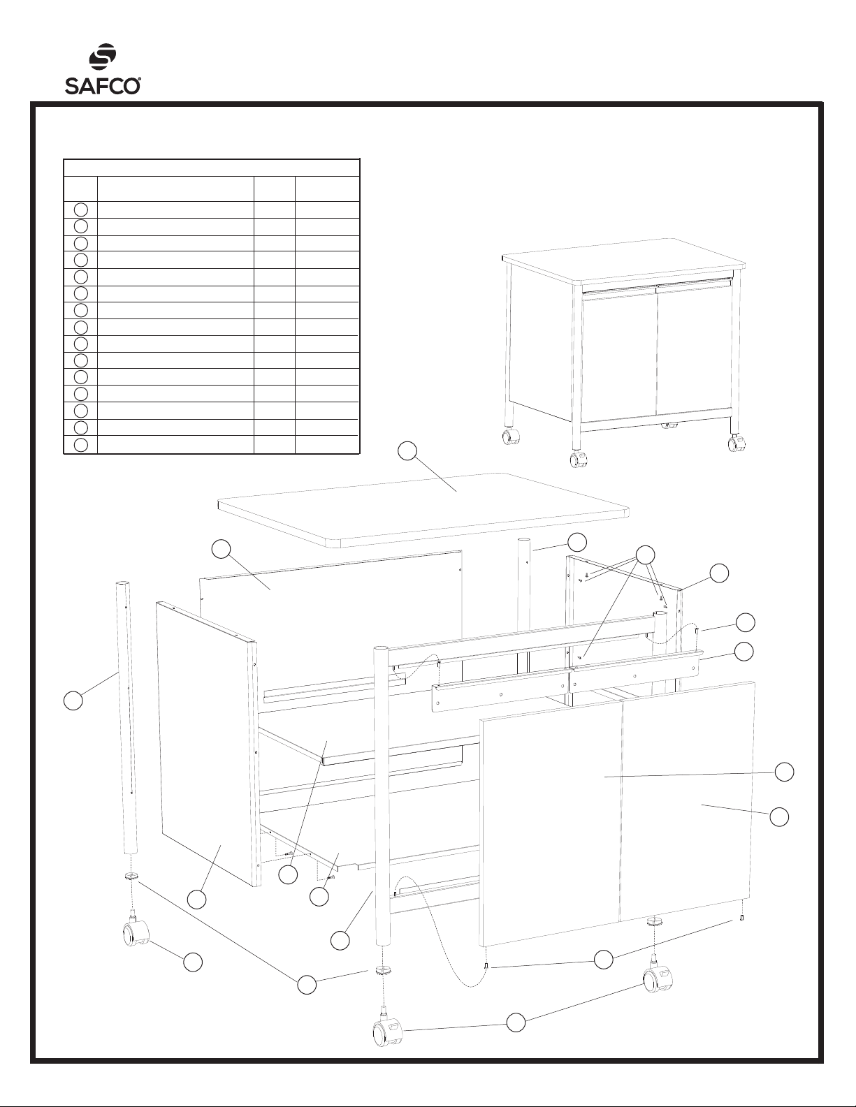
Deluxe Machine Stand
an LDI Spaces Company
Minneapolis, MN 55428
www.safcoproducts.com
LETTER
CODE
A
Top Panel 1 1872-01
B
Front Leg Frame 1 1872-02
C
Side Panel 2 1872-03
D
Back Panel 1 1872-04
E
Rear Leg 2 1872-05
F
Bottom Shelf 1 1872-06
G
Inner Shelf 1 1872-07
H
Door Handle 2 1872-08
I
Plastic Bushing 4 1872-32
J
Left Door Panel 1 1872-09
K
Right Door Panel 1 1872-10
L
Screw 26 1872-23
M
Caster Insert 4 1872-22
N
Caster without Brake 2 1874-25
O
Caster with Brake 2 1874-24
DESCRIPTION
TOOLS REQUIRED: Phillips Screwdriver,
Hammer or Rubber Mallet
ASSEMBLY INSTRUCTIONS
PARTS LIST
PART NO.
MODEL NUM-
1872
BER
For questions or concerns, please call
Safco Consumer Hot Line 1-800-664-0042
available Monday-Friday 7:30 AM to 5:00 PM (Central Time)
(English-speaking operators)
A
ASSEMBLED
UNIT
D
E
L
C
I
H
E
J
K
G
C
F
B
N
I
M
O
100187237: 1 of 2; Rev A: Rev Date 27-JUN-2016 Safco Products Company, New Hope, MN 55428
Page 2
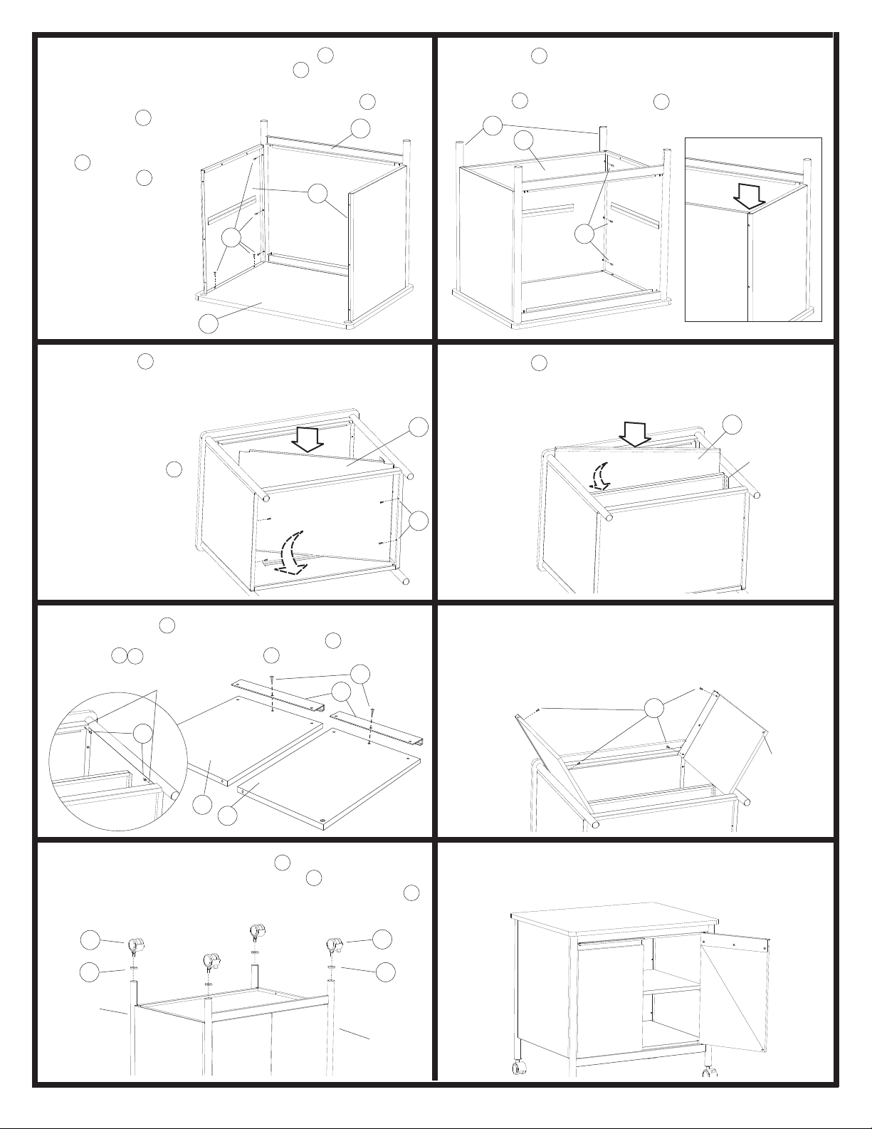
Work on a smooth, clean surface. Place the A Top Panel face
1
down with the holes up. Position one C Side Panel on one
end of the Top Panel with the fl anges toward the center of the
unit. Fasten the Side Panel to the Top Panel with two L Screws
Attach the B Front
Leg Frame to the
Side Panel using
L Screws. Attach
the other C Side
Panel in the same
manner.
A
Slide the D Back Panel into position between the Side Panels
2
as shown in the inset. Keep the Back Panel inside the fl anges
on the Side Panels. Fasten the Side Panel and Back Panel
to each E Rear Leg using three L Screws from the interior.
E
D
L
Slide the F Bottom Shelf into the unit between the Side Panels,
3
with the fl anges toward the bottom end of the unit. Slide the
fl anges of the shelf into the lower fl anges on the Side Panels
and Back Panel.
Fasten the Bottom
Shelf to each Side
Panel using two L
Screws per side.
Slide the four I Plastic Bushings onto the pins on each side
of the Front Leg Frame. Loosely fasten the H Door Handles to
5
the J , K Door Panels with one L screw in each center hole.
PINS
I
H
Slide the G Inner Shelf into the unit between the Side Panels,
with the fl anges toward the bottom end of the unit. Slide the
4
fl anges of the shelf into the shelf holders on the Side Panels
and Back Panel.
F
L
Position one Door Panel with the magnetic insert upward as
6
shown. Slide bottom hole in the door onto one Plastic Bushing; tilt the Door Handle and slide it onto the upper Bushing.
L
Fasten the handle to the door using two more Screws. Repeat
for the other door.
L
G
SHELF
HOLDER
MAGNET
K
J
Use a hammer or mallet to tap one M Caster Insert into each
7
of the four legs. Push the stems of the N Casters without
Brakes into the caster inserts in the Rear Legs. Push the O
Casters with Brakes into the inserts in the Front Legs.
N
M
REAR
LEG
100187237: 2 of 2; Rev A: Rev Date 27-JUN-2016
O
M
FRONT
LEG
Carefully turn the completed unit upright. To align the doors,
8
slightly loosen the screws in the handle, adjust, and re-tighten
the screws.
Safco Products Company, New Hope, MN 55428
 Loading...