

Page 1
Contents
1. GENERAL INFORMATION
.............................................................................................................45
2. TECHNICAL CHARACTERISTICS
...................................................................................................45
3. DIMENSIONS OF THE STOVE
........................................................................................................46
4. FUEL
.........................................................................................................................................46
5. CHIMNEY
...................................................................................................................................47
6. COMBUSTION
AIR........................................................................................................................47
6.1 COMBUSTION AIR INLET: CONVENTIONAL
................................................................................47
6.2 COMBUSTION AIR INLET: SEPARATE / EXTERNAL
.....................................................................47
7. INSTALLATION OF THE
STOVE......................................................................................................48
8. CONNECTION OF THE STOVE TO THE
CHIMNEY.............................................................................49
9. BEFORE FIRST
USE.....................................................................................................................49
10. THE
CONTROLS..........................................................................................................................4
9
11. WARNING!PLAYING
CHILDREN!..........................................................................................54
Page 2

12.
KINDLING...............................................................................................................................
....54
13. STOKING UP OF THE FIRE WITH WOOD – FIREWOOD
....................................................................55
14. STOKING UP OF THE FIRE WITH WOOD – OPERATION
...................................................................55
15. STOCKING UP THE FIRE WITH WOOD – REMOVAL OF THE
ASH......................................................55
16. REMOVAL OF THE
ASH................................................................................................................55
17. CLEANING –
IMPORTANT!........................................................................................................55
18. SPARE
PARTS............................................................................................................................56
19. FAULTS
.....................................................................................................................................56
20.
GUARANTEE...........................................................................................................................
...57
Please keep in a safe place! Subject to amendment!
Sketches are not contractually binding!
45
1. General information
Dear user!
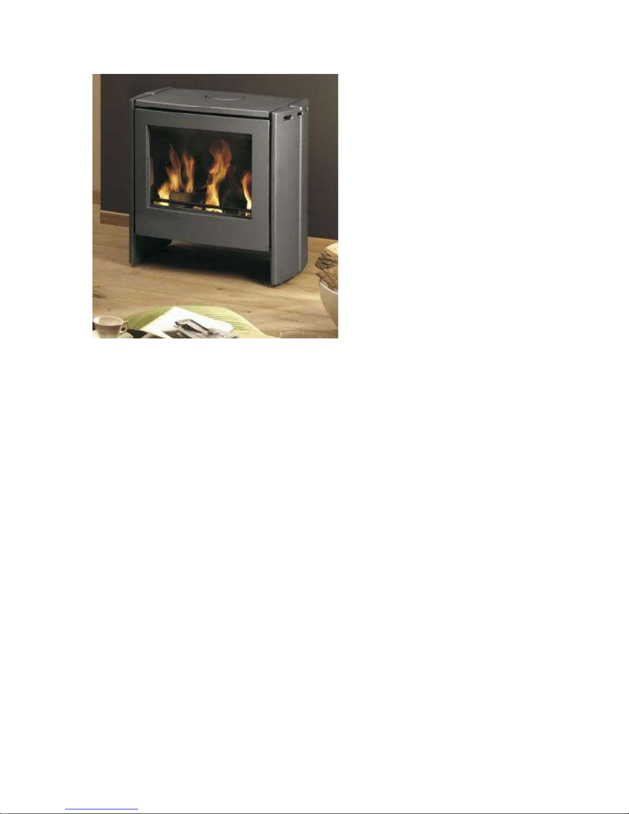
When you purchased this SAEY Scope wood-burning stove, you chose a modern and innovative
combustion
and heating appliance. Our warmest congratulations!
We devoted a lot of attention to the technology, but also to the materials used, the processing and the
compactness of the appliance. This enables us to guarantee problem -free operation.
The SAEY Scope was built according to innovative techniques and in accordance with the European
norm
EN 13240 (in the case of Germany, in accordance with DIN 18891-A1).
If you wish to achieve maximal performance in terms of ecological and economical considerations, you
should comply with this installation and operation manual and carry out its instructions.
If the wood-burning stove is damaged due to non-compliance with the installation and operation
manual, the
guarantee will no longer be valid.
If the wood-burning stove is built in, the applicable laws and local regulations regarding fire prevention
and
architecture should be complied with.
2. Technical characteristics
TYPE SAEY Scope
Maximum heating capacity kW 11
Performance class % 1 (h>70)
Dimensions of the stove
Page 3
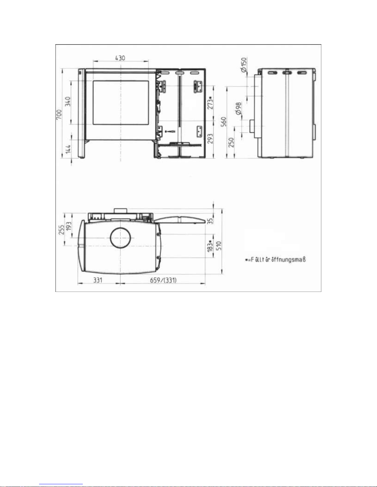
Height mm 700
Width mm 662
Width with fully open right external wall mm 990
Depth mm 510
Height up to lower edge of connector pipe mm 485
Outside diameter of the connector pipe Ø mm 150
Connector pipe for combustion air Ø mm 100
Height up to lower edge of ventilation pipe mm 225
Small filler door opening mm 270 x 180
Maximum length of the firewood mm 500
Weight of the stove
Not packaged about kg 213
Packed about kg 236
Specifically for the German market, the following information for determining the dimensions of
the
chimney according to DIN 4705 T1/T2, at nominal thermal capacity.
Fuel
Firewood / wood briquettes in
accordance with the DIN 51
731 norms
Flue gas mass flow g/s 14,8
Average temperature of the outlet duct °C 330
Page 4

Minimal pressure Pa 12
Minimal pressure at 0,8 times the nominal thermal
capacity
Pa 8
46
3. Dimensions of the stove
4. Fuel
The SAEY Scope wood-burning stove is intended exclusively for burning and heating with
wood, and
is equipped with a grate.
Wood: All types of dry firewood.
Dry wood means solid pieces of wood, of which the moisture content with regard to the weight of dried
wood should not be more than 20%.
Use prepared wood or finely chopped wood (splintery wood) to kindle the fire!
Refuse, wood chips, wood shavings and sawdust, tree-bark and bits of chipboard, laminated wood and
wood with a treated surface may not be used.
Do not chop the firewood too small. Very thin firewood only burns for a short time, and is only suitable
for
lighting the stove. Allow large pieces of the customary size of about 50 cm to burn up naturally. Round
logs must be chopped into smaller pieces.
Firewood
SAEY Scope
Max. length of the firewood 50 cm
Max. circumference 30 cm
Max. moisture content 20%
Filling quantity (at nominal thermal capacity) about 3 kg
Max. filling quantity about 6 kg
Dimensions of the filler door
opening
47
ONLY DRY WOOD WILL PREVENT THE EMISSION OF
HARMFUL
SUBSTANCES DURING COMBUSTION!
WARNING! The wood-burning stove is not a refuse incinerator. Environmental legislation expressly
prohibits
the burning of refuse in domestic fireplaces. A person who misuses his solid-fuel fireplace for burning
household refuse, chemically treated wood remnants or old paper or uses it as a private refuse
incinerator is
not only damaging the environment, but is also contravening the 'Bundesimmissionsschutzgesetz'
(Federal
Emission Control Act), and can be punished.
Apart from the high, uncontrolled levels of air pollution, the harmful combustion products and
combustion
residues also have a detrimental effect on the operation and life span of the wood-burning stove and
the
chimney. This results in multiple defects and rapid wear and tear, which will require expensive
reconditioning
measures and could even necessitate replacement of the wood-burning stove.
THE GUARANTEE IS NO LONGER VALID IF REFUSE HAS
BEEN
BURNT!
5. Chimney
Before the stove is set up and built in, it should be ascertained whether the dimensions and the quality
of
Page 5

the chimney comply with the locally applicable regulations (for Germany: DIN 18160); the dimensions
must
be calculated if necessary.
Before the stove is built in, the qualified chimney sweep must be asked whether the chimney and
the
combustion air supply are suitable.
6. Combustion air
The SAEY Scope wood -burning stove can only be used when the door of the stove is closed. The
SAEY
Scope wood-burning stove consumes 28m³ of air at its nominal capacity.
Other fireplaces or air outlets in the same space or with the same combustion air connection, must be
taken
into account.
If necessary, the combustion air connection must be calculated, or a separate combustion air supply
must
be installed outside.
Tip: cooker hoods that could be connected to the space in which the stove is set up, must certainly be
taken into account. They cause an under pressure that could lead to disturbances in the combustion
air
supply. The combustion gas that is released is highly dangerous and could be harmful to the health of
the
house occupants.
6.1 Combustion air inlet: conventional
The SAEY Scope wood -burning stove obtains its combustion air solely via the air slider (air inlet) on
the rear. It is therefore important to ensure that the air supply is functioning correctly.
6.2 Combustion air inlet: separate / external
The combustion air supply can also be closed, i.e. via a direct supply of air from the outside (special
attachment: connector pipe for combustion air essential) to the wood-burning stove. It must be
ascertained beforehand whether the combustion air can be conveyed from the external air connection
of the house to the space where the stove will be installed.
If a smooth pipe with a diameter of 100mm is used, 12m of pipe can be connected. If adapters such as
elbow joints are used, the maximum length of the pipes should be decreased by 1m per adapter. E.g.
10m of pipe + 2 elbow joints = 12m of pipe.
48
7. Installation of the stove
Only an appliance that is connected by a recognised installer guarantees compliance with the
guidelines
regarding architecture and fire prevention. This is certainly necessary for correct and safe operation of
the
stove.
The chimney plays a very important role in the connection of the stove. The qualified chimney-sweep
must
therefore certainly be consulted about the connection, so that the applicable regional building
regulations
are complied with.
Take the following into consideration:
The appliance can only be used when the door of the stove is closed. The doors of the stove must
also
be closed when the appliance is not in use.
There must be an adequate supply of fresh air during operation of the appliance.
Fire protection measures with regard to flammable or heat-sensitive floor coverings:
The floor below the stove must be covered by a fireproof, non -flammable surface (e.g. cast-iron
plate,
marble, tiles, etc.).
No flammable or heat-sensitive objects may be stored below the appliance (e.g. supply of firewood).
Safety distances from flammable or heat-sensitive objects:
Page 6
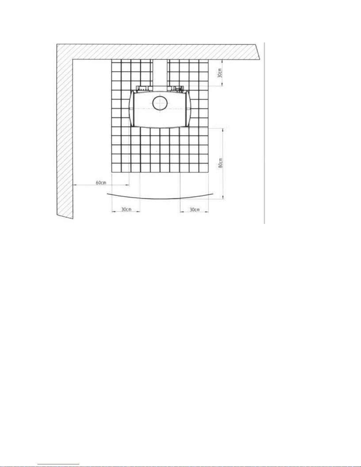
From the side walls of the stove: at least 60 cm
From the rear: at least 30 cm
Within the radiation range of the glass: at least 80 cm
Floor protection in front of the appliance: at least 50 cm
Floor protection at the sides: at least 30 cm
49
8. Connection of the stove to the chimney
The stove can be connected directly to the chimney (outlet at the back). The diameter of the outlet duct
must correspond with the 150mm diameter of the stove’s outlet connector.
If the draught of the chimney is too strong, a draught regulator must be built in.
You must also take the following into account with regard to the diameter of the outlet duct:
The diameter of the outlet duct may not be reduced. In addition, the outlet duct must fit perfectly onto
the
chimney.
The stove duct may not be smaller than the diameter of the chimney, since this will hamper the
upward
pressure of the fumes. In order to prevent this, you should provide a double wall lining.
The chimney connections of different fireplaces may not be situated opposite one another or at the
same
height, since this could also hamper the removal of combustion gases. Two connections of fume outlet
ducts must be situated at least 30 cm away from one another.
The chimney may not contain too many connections – this hampers the upward pressure. Consult
your
chimney-sweep!
The chimney may not conduct any false air. Check for closed chimney sliders and cleaning hatches
in
the cellar or on the roof!
The outlet duct must be securely attached to the connector pipe.
9. Before first use
Page 7
When the heating appliance is used for the very first time, it must first dry out completely. For this
purpose,
heat it for one hour with a small quantity of fuel. Set the air inlet to
“ I “.
During this phase, a slight odour may be given off due to the curing of the primer used.
Keep an eye on the appliance during this phase and immediately remove any water formed by
condensation, before it can burn into the enamel or the lacquer.
10. The controls
Adjustment of the feet
In order to make levelling of the appliance possible, the feet on both sides have small setscrews that
can be
adjusted separately.
50
Opening the door
Page 8
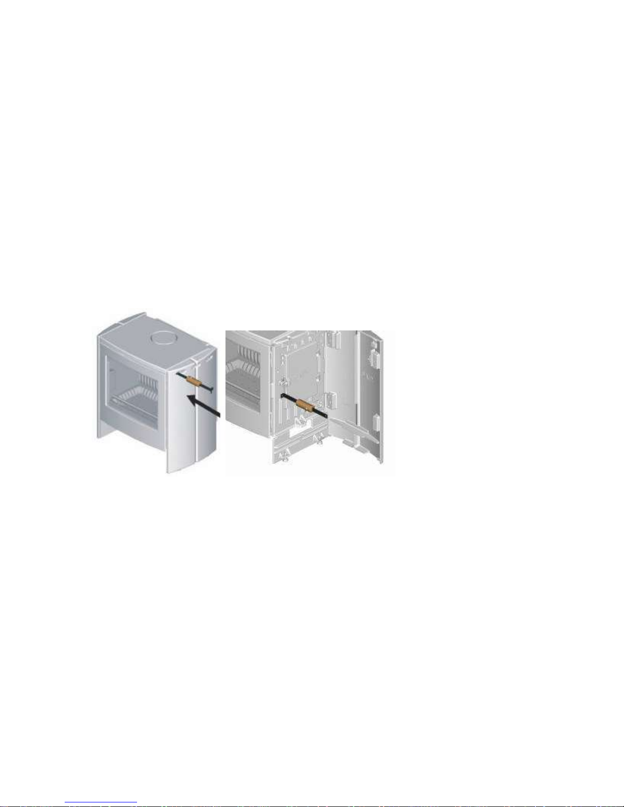
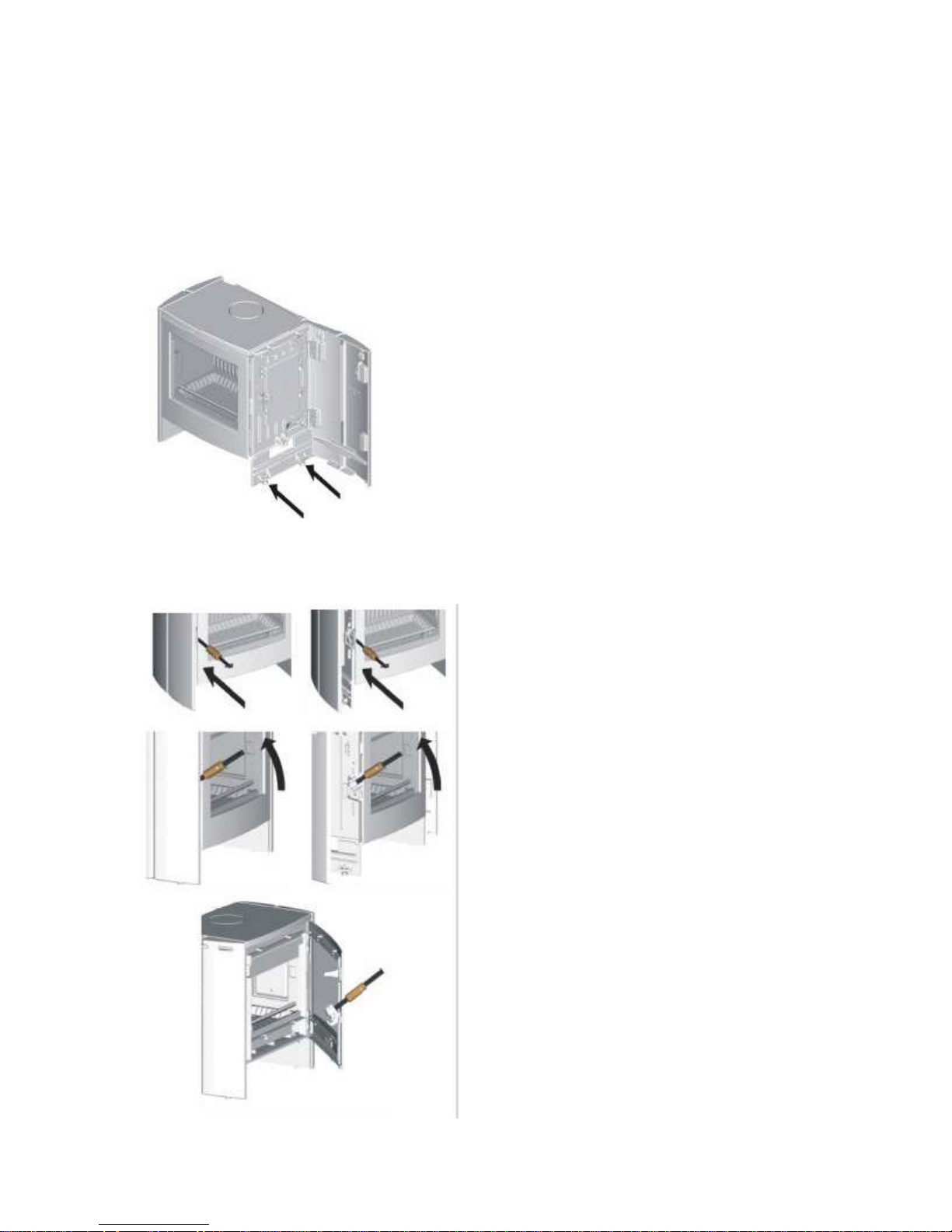
The control handle is inserted horizontally in the centre of the door, in the groove between the left side
wall
and the door in the sealer plate, and is pushed up against the lining. Now pull the control handle
upwards,
and the door will open. If desired, the left side wall can be opened slightly in order to insert the control
handle even more securely in the sealer plate (see: opening of the side wall). This is advisable in the
case of
enamelled appliances, in order to prevent scratches on the enamel.
Opening and removal of the side walls
The left and right side walls can be removed to facilitate transport. To do this, open the sidewall
concerned
and then lift it up and off its hinges. The right side wall must also be opened to fill the wood-burning
stove
with fuel via the side filler door. The side walls can be opened with the aid of the control handle: to do
this,
insert the flat side of the control handle into the first groove of the applicable side wall (front of the
appliance), and push it up against the cylindrical pin situated behind it. The side wall can now be
opened by
pulling gently.
51
Opening of the filler door
Before the fireplace can be filled via the side filler door, the right side wall must be opened, as
described
above. The curved side and stylus of the control handle are first hooked into the opening of the filler
door
lock, and pulled upwards.
Operation of the primary air inlet
Page 9
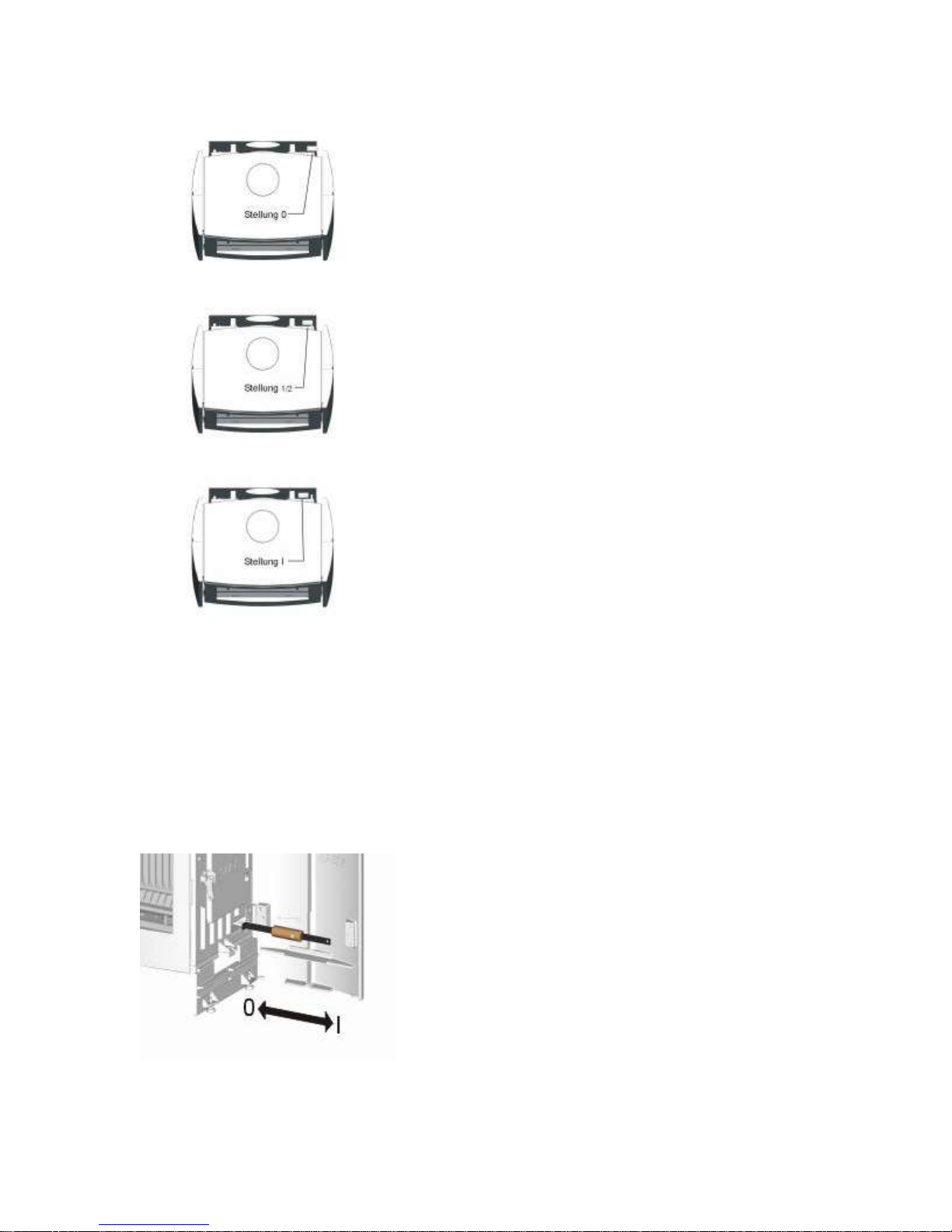
A primary air inlet is situated on the rear of the appliance to facilitate regulation of the air supply and
the
post-combustion air via the openings above the glass. These can be regulated by means of the knob
of the
air slider on the right, behind the cover plate. Another marking is visible on the upper end of the rear.
The stop to the right is position “0”, and indicates no air supply. The stop to the left is position “l”, and
indicates maximum air supply. The central position therefore indicates a 50% air supply. After a while,
you
will instinctively know how to use the appliance most effectively by setting the corresponding positions
of the
primary air slider and the combustion air inlet.
52
Operation of the combustion air inlet
For more accurate control of the burning up of the fuel, an additional combustion air inlet is located
underneath the grate, against the rear wall inside the appliance. This inlet can be adjusted with the aid
of the
Page 10
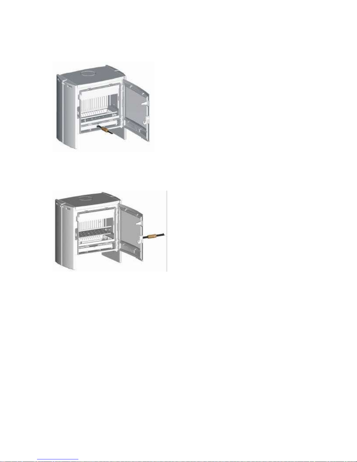
control handle, as indicated in the illustration. In position “0” the cast-iron knob is fully recessed in the
sidewall, and in position “l” it is fully extended (see: division on inner surface of the side wall).
Removing the ash pan before cleaning
Depending on the quantity of ash, the ash pan must be emptied regularly – certainly before the level of
the
ash reaches the grate. To do this, hook the pin of the control handle into the front plate of the ash pan
and
carefully pull it out of the appliance so that it can be emptied.
Removal of the grates
After regular use (depending on the quantity of ash), the grates must be cleaned thoroughly. To do
this,
remove the standing grate on the front from its supports and then remove the wood grate from the
frame.
After the ash pan has also been removed from the appliance and the appliance has cooled down
completely, it can be cleaned with a vacuum cleaner.
53
Removing the inspection cover
Page 11
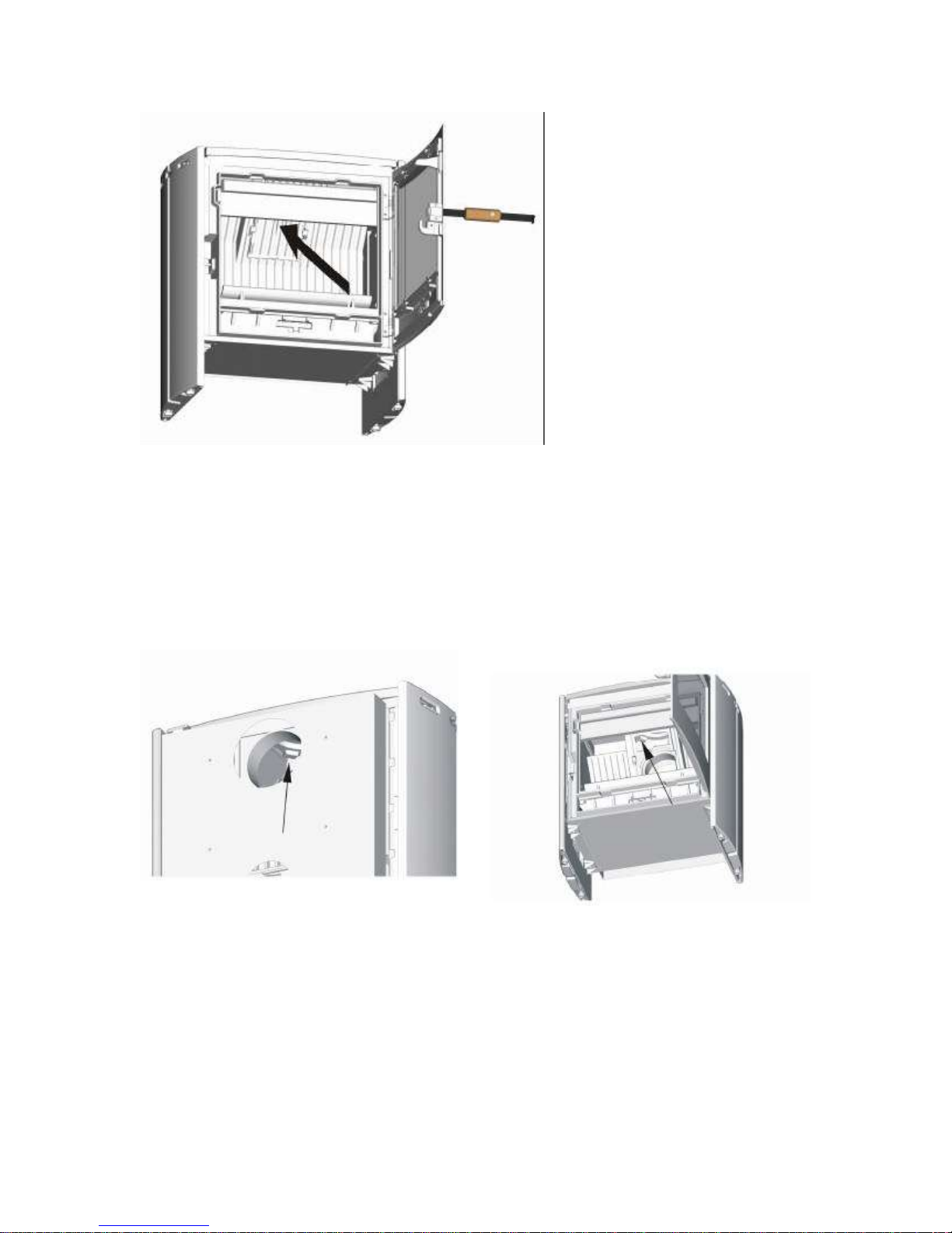
Once per heating season (preferably at the end of the season), the inspection cover must be removed
from
the appliance in order to remove the ash powder from the backflow preventor. The inspection cover
must
also be removed if you decide to use the top outlet instead of the one on the rear of the appliance
(see:
changing the fume outlet duct). To do this, grip the cover in the centre of the rib and tilt it upwards to lift
it
from its supports. Now you can also remove any ash powder deposited on the rear of the appliance
with a
vacuum cleaner.
Changing the fume outlet duct
If necessary, the fume outlet duct connection (factory setting: on rear), can also be altered to be
situated at
the top. A separate connector pipe (special attachment) is required for this. First remove the inspection
cover from the appliance (as described above). Then lift out the sunken cover in the cover plate and
remove
it through the opening of the inspection cover. Now insert the connector pipe through this opening and
reattach it to the same anchor point. Finally, insert the sunken cover through this opening and reattach
it to
the rear from the inside, and replace the inspection cover.
54
Assembly of the combustion air connector pipe
Page 12

If necessary, an additional connector pipe for the combustion air (special attachment) can be attached
to
the rear of the wood-burning stove, so that the combustion air will not be supplied centrally. To do this,
the radiation plate must first be loosened from its 4 anchor points. In addition, the cotter pin must be
removed from the air inlet shaft at the bottom, so that the shaft and the handle can be dismantled.
Once
these sections have been removed, the combustion air connector pipe and the seal can be screwed
down on the rear. Now you should manually slide the air inlet completely to the right (rear view/position
“0”), and attach the handle again; set it to position “0” (left rib lining). Finally, rotate the shaft through
the
side opening of the combustion air connector pipe until the short corner fits into the bottom opening of
the air inlet handle again. Replace the cotter pin and attach the radiation plate on the rear. The
combustion air can now be supplied directly via an Aluflex pipe (100mm diameter).
11. WARNING! PLAYING CHILDREN!
A stove gets hot! Particularly the cover plate, the protective
casing and the glass.
You should therefore ascertain that there are no playing
children in the area before lighting the stove.
The safety measures cannot rule out the possibility of
accidents completely.
KEEP SMALL CHILDREN AWAY FROM THE VICINITY OF THE STOVE AS MUCH AS POSSIBLE!
12. Kindling
Set the air inlet to maximum for the lighting of the stove.
Through the filler door opening, spread out a broad layer of small kindling-wood on the floor of the
combustion chamber. Now lay the required quantity of firewood on top. Place a thin layer of firewood
op top
of this, and then a bit of splintery wood.
Use about 3 matches to light all the wood. We suggest the following: one match at the back and two at
the
front. This will ensure that everything ignites well.
You could also use 4-5 firelighters. Now add a small quantity of fuel. Close the door firmly after the fire
has
been lit.
55
13. Stoking up of the fire with wood – Firewood
(The appliance can also be filled via a side door!)
To ensure that the appliance rapidly reaches the desired temperature so that the release of harmful
Page 13

substances is kept to a minimum, you must follow the following heating method after kindling the fire:
Place 3-4 small pieces of wood, max. 2,5 kg in size, in the appliance in two l ayers; set the primary air
inlet
to position “l”. The combustion air inlet in the sidewall must also be open.
Top up further with a maximum of 3kg (2-3 pieces of wood, one layer); after kindling the wood (about
10
minutes), the setting of the combustion air inlet must be changed from position “l” to position 1/2.
14. Stoking up of the fire with wood – Operation
Wood burns for a long time and emits a lot of gas; it must be burnt rapidly and with a constant supply
of
oxygen. To prevent possible detrimental effects due to prolonged periods of reduced air supply, it is
advisable to let the SAEY Scope burn at its maximum capacity for 15 minutes every day.
Possible detrimental effects:
Smouldering fire, condensation and tar deposits
Heavy soot deposits
Inconvenience caused by smoke (emission of harmful substances)
Risk of explosion
WOOD IS NOT SUITABLE FOR A SMALL FIRE OR ONE THAT BURNS FOR A LONG TIME!
However, it could take a while for the wood to burn up completely. This means that, by closing the air
inlet
on the rear, the set temperature is only reached once the wood is almost burnt up and the degassing
process – the large flames die down and the wood has been reduced to glowing embers – has been
completed!
In particular, you should avoid adding too much fuel, since this will result in excessive heat emission as
well
as a high level of emission of combustion gases.
15. Stocking up the fire with wood – Removal of the ash
Correct stoking up of the fire with wood will ensure that the volume of ash is reduced to a minimum.
Thus,
the remaining charcoal can also burn up in the glowing embers.
16. Removal of the ash
The ash pan may be maximally filled with ash to the top; an ash cone should not be allowed to
develop,
since this could prevent the grates from cooling down, which could cause the cast-iron components to
melt.
While the stove is in use, the doors must be closed; otherwise the appliance could be damaged due to
overheating.
17. Cleaning – IMPORTANT!
The heating duct must be cleaned at the end of the heating season. Upon removal of the cleaning
slider on
the flame retaining plate (on the inside of the rear wall), the heating duct will be accessible. Now you
can
easily remove the ash powder from the heating duct and the connector pipe. Now replace the cleaning
slider again.
56
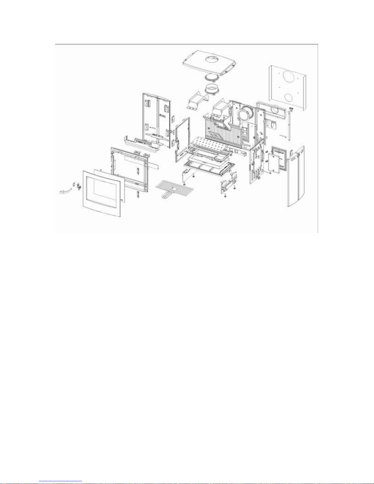
18. Spare parts
You can obtain spare parts from your dealer.
Page 14
19. Faults
Malfunctioning
Cause Solution
Wood too moist Check; max. residual moisture 20%
Wrong fuel Use only the fuel allowed for the appliance
Chimney draught too weak:
(Minimal pressure: 10Pa at the heating
gas connector pipe)
Check the air-tightness of the outlet
Light a kindling fire in the chimney
Close any open doors of other appliances
connected to the chimney.
Close the cleaning hatches of the chimney
If necessary, clean the connector pipe
The fire is not burning well
Not enough combustion air Connect the combustion air pipe directly to
the appliance, and convey combustion air
to the circulation grate or directly to the
outside
Check the diameter of the circulation
Check the ventilation installation of the
residence or cooker hood, and open a
window if necessary
Wood too moist Check; max. residual moisture 20%
Wrong fuel Fuel not small enough – max.
circumference is 50 cm
Use only the fuel allowed for the appliance
Glass soon gets dirty
Too much wood has been added Do not add more than 2 to 3 pieces of wood
 Loading...