

Saeco Phedra Evo D.A. 5P2015, Phedra Evo D.A. 5P2015T, Phedra Evo D.A. 5P2015A, Phedra Evo D.A. 5P2015AT Operation And Maintenance
Page 1

Vending Machine
UK
WARNING: This instruction manual is intended exclusively for specialized personnel.
OPERATION AND MAINTENANCE
Page 2
English
2
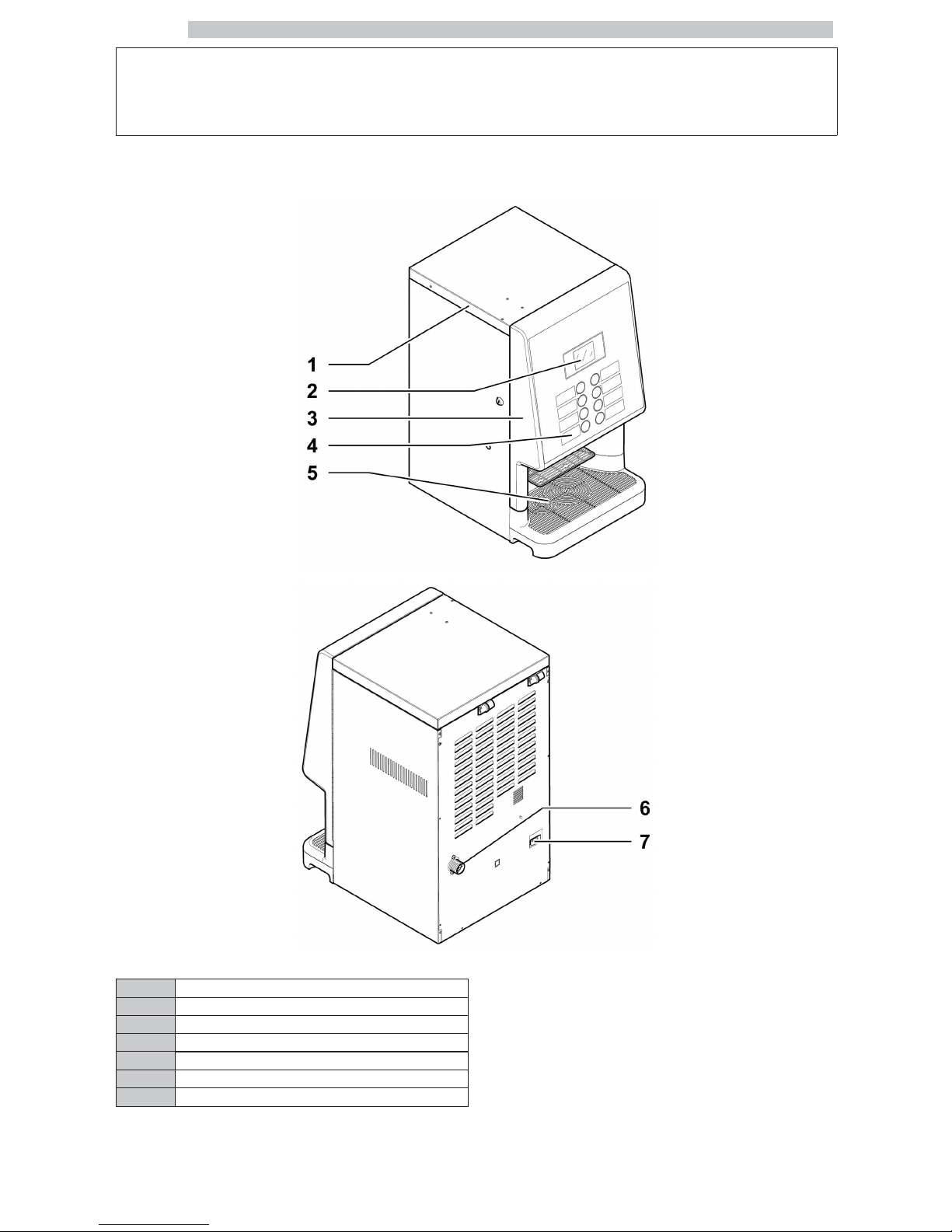
MAIN PARTS
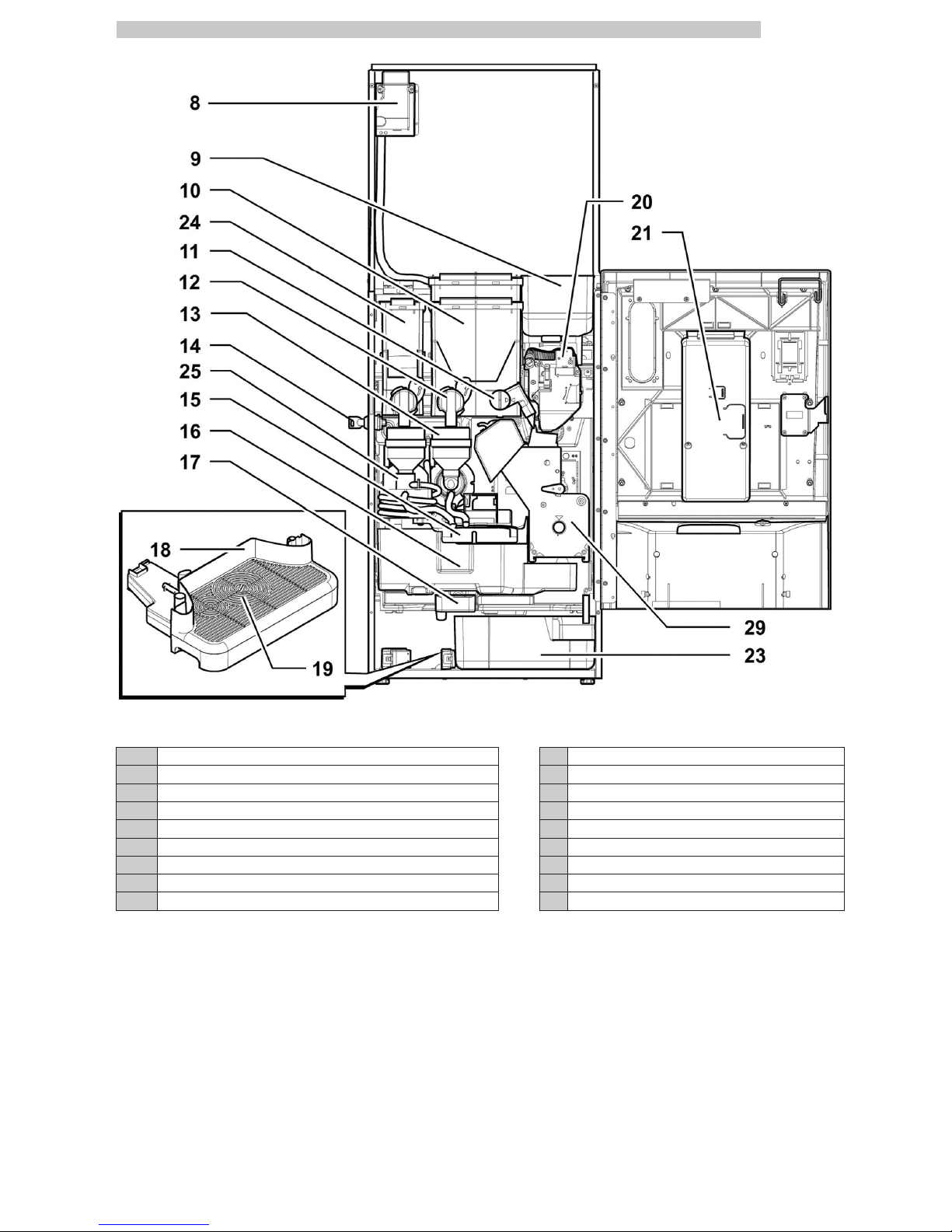
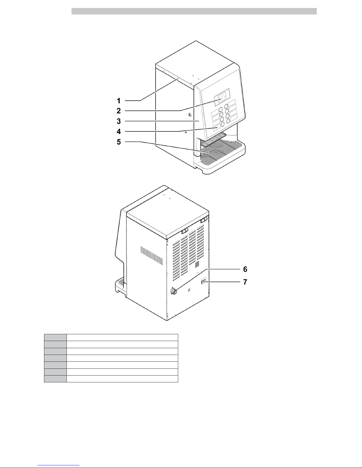
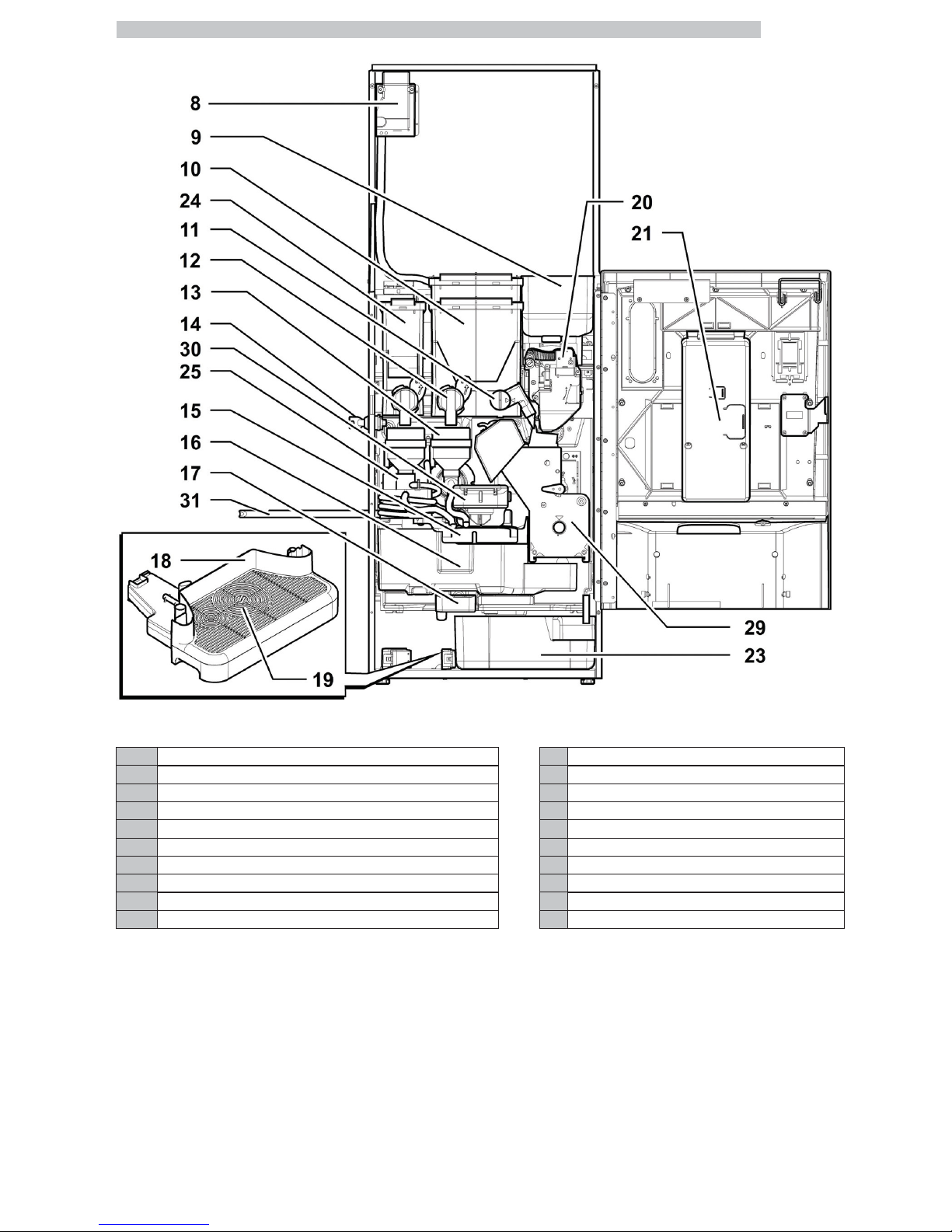
MAIN PARTS - ESPRESSO VERSION
1 Top door
2 Display
3 Front door
4 Keypad
5 Dispensing outlet (beverage dispensing)
6 Water connection coupling
7 Power cord socket
Page 3
English
3
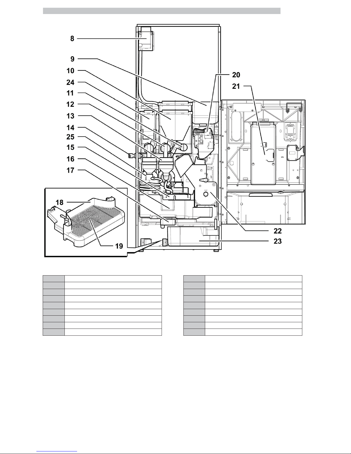
8 Safety switch 17 Drain conveyor
9 Coffee bean hopper 18 Drip Tray
10 Container 2/3 (instant products) 19 Grill
11 Adjustable powder dispensing channel 20 Coffee grinder
12 Instants opening 21 CPU card
13 Mixer 22 Brew group
14 Door lock 23 Coffee grounds drawer
15 Dispensing arm 24 Container 1 (instant products)
16 Coffee grounds drawer 25 Spiral mixer
Page 4

English
4
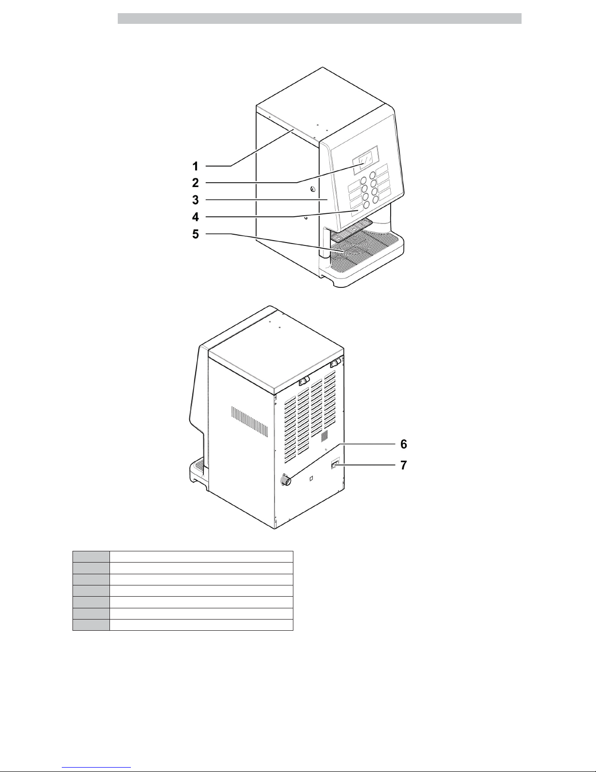
MAIN PARTS - ESPRESSO WATER TANK VERSION
1 Top door
2 Display
3 Front door
4 Keypad
5 Dispensing outlet (beverage dispensing)
7 Power cord socket
26 Tank funnel door
Page 5
English
5
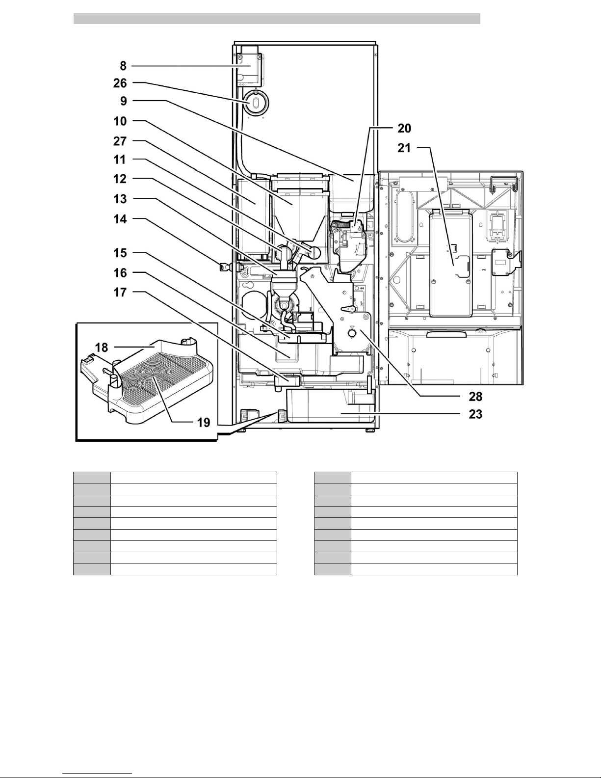
8 Safety switch 17 Drain conveyor
9 Coffee bean hopper 18 Drip Tray
10 Container 2/3 (instant products) 19 Grill
11 Adjustable powder dispensing channel 20 Coffee grinder
12 Instants opening 21 CPU card
13 Mixer 23 Coffee grounds drawer
14 Door lock 26 Tank funnel door
15 Dispensing arm 27 Water tank
16 Coffee grounds drawer 28 Brew group Gusto
Page 6
English
6
MAIN PARTS - ESPRESSO T.T.T. VERSION
1 Top door
2 Display
3 Front door
4 Keypad
5 Dispensing outlet (beverage dispensing)
6 Water connection coupling
7 Power cord socket
Page 7
English
7
8 Safety switch 17 Drain conveyor
9 Coffee bean hopper 18 Drip Tray
10 Container 2/3 (instant products) 19 Grill
11 Adjustable powder dispensing channel 20 Coffee grinder
12 Instants opening 21 CPU card
13 Mixer 23 Coffee grounds drawer
14 Door lock 24 Container 1 (instant products)
15 Dispensing arm 25 Spiral mixer
16 Coffee grounds drawer 29 T.T.T. Brew group
Page 8
English
8
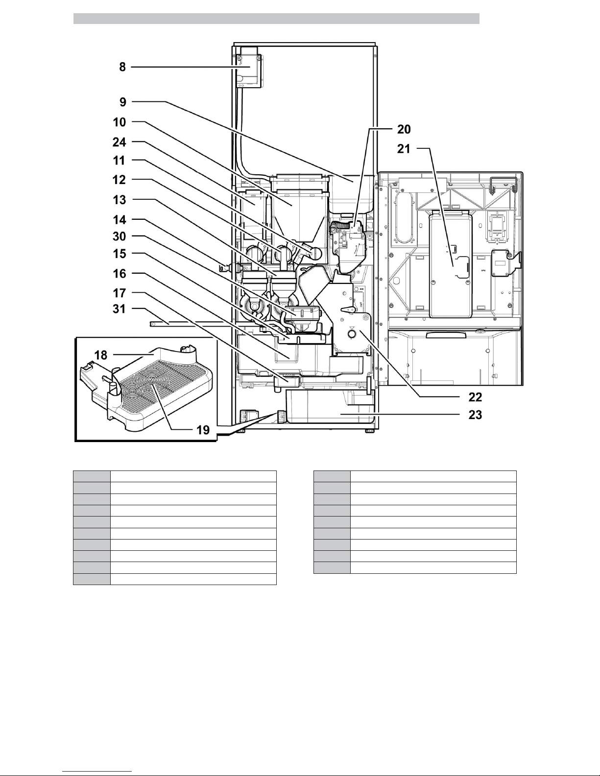
MAIN PARTS - CAPPUCCINO VERSION
1 Top door
2 Display
3 Front door
4 Keypad
5 Dispensing outlet (beverage dispensing)
6 Water connection coupling
7 Power cord socket
Page 9
English
9
8 Safety switch 18 Drip Tray
9 Coffee bean hopper 19 Grill
10 Container 2/3 (instant products) 20 Coffee grinder
11 Adjustable powder dispensing channel 21 CPU card
12 Instants opening 22 Brew group
13 Mixer 23 Coffee grounds drawer
14 Door lock 24 Container 1 (instant products)
15 Dispensing arm 30 Cappuccinatore
16 Coffee grounds drawer 31 Hose for Cappuccinatore
17 Drain conveyor
Page 10
English
10
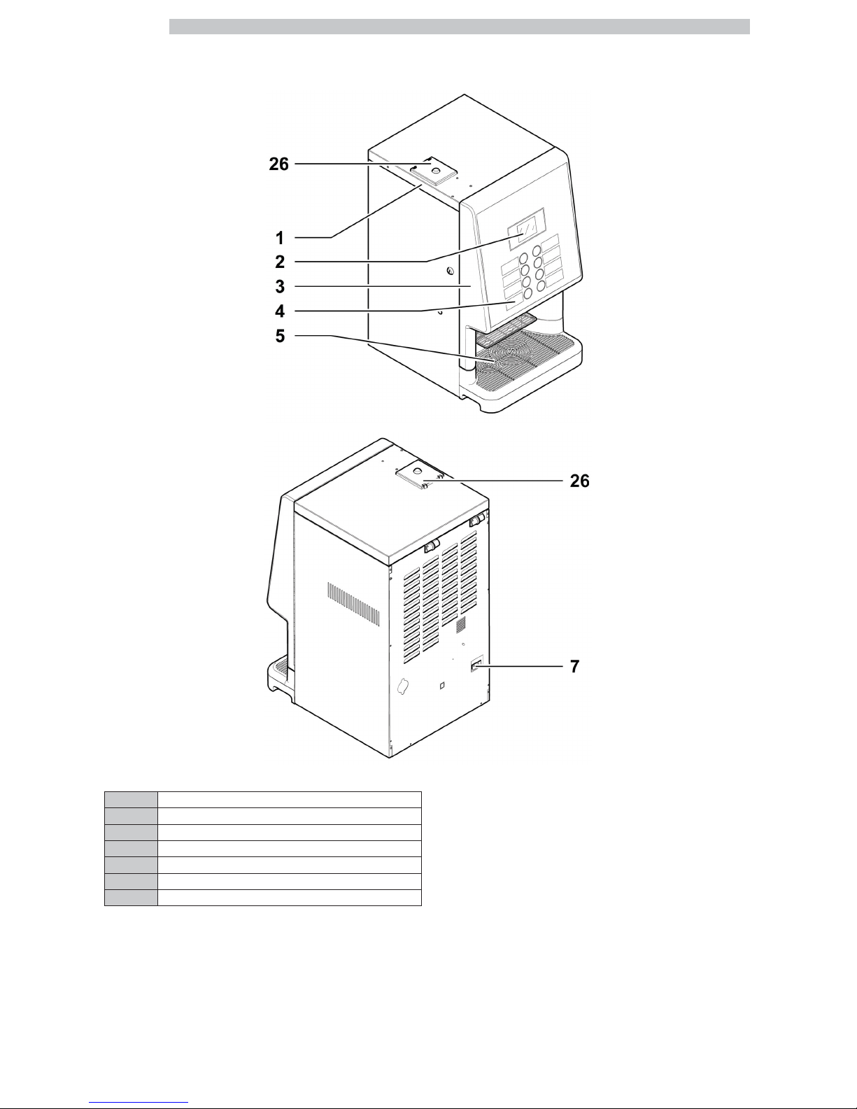
MAIN PARTS - CAPPUCCINO WATER TANK VERSION
1 Top door
2 Display
3 Front door
4 Keypad
5 Dispensing outlet (beverage dispensing)
7 Power cord socket
26 Tank funnel door
Page 11

English
11
8 Safety switch 18 Drip Tray
9 Coffee bean hopper 19 Grill
10 Container 2/3 (instant products) 20 Coffee grinder
11 Adjustable powder dispensing channel 21 CPU card
12 Instants opening 23 Coffee grounds drawer
13 Mixer 26 Tank funnel door
14 Door lock 27 Water tank
15 Dispensing arm 28 Brew group Gusto
16 Coffee grounds drawer 30 Cappuccinatore
17 Drain conveyor 31 Hose for Cappuccinatore
Page 12

English
12
MAIN PARTS - CAPPUCCINO T.T.T. VERSION
1 Top door
2 Display
3 Front door
4 Keypad
5 Dispensing outlet (beverage dispensing)
6 Water connection coupling
7 Power cord socket
Page 13
English
13
8 Safety switch
18
Drip Tray
9 Coffee bean hopper
19
Grill
10 Container 2/3 (instant products)
20
Coffee grinder
11 Adjustable powder dispensing channel
21
CPU card
12 Instants opening
23
Coffee grounds drawer
13 Mixer
24
Container 1 (instant products)
14 Door lock
25
Spiral mixer
15 Dispensing arm
29
T.T.T. Brew group
16 Coffee grounds drawer
30
Cappuccinatore
17 Drain conveyor
31
Hose for Cappuccinatore
Page 14

English
14
SAFETY INSTRUCTIONS
For professional use only.
The vending machine
cannot be installed
outdoors; avoid placing it
in areas where the
temperature is less than
2°C or more than 32°C
and in particularly dump or
dusty areas.
Do not install the appliance
in a location where water
jets may be used.
The vending machine must
be installed on a flat
surface.
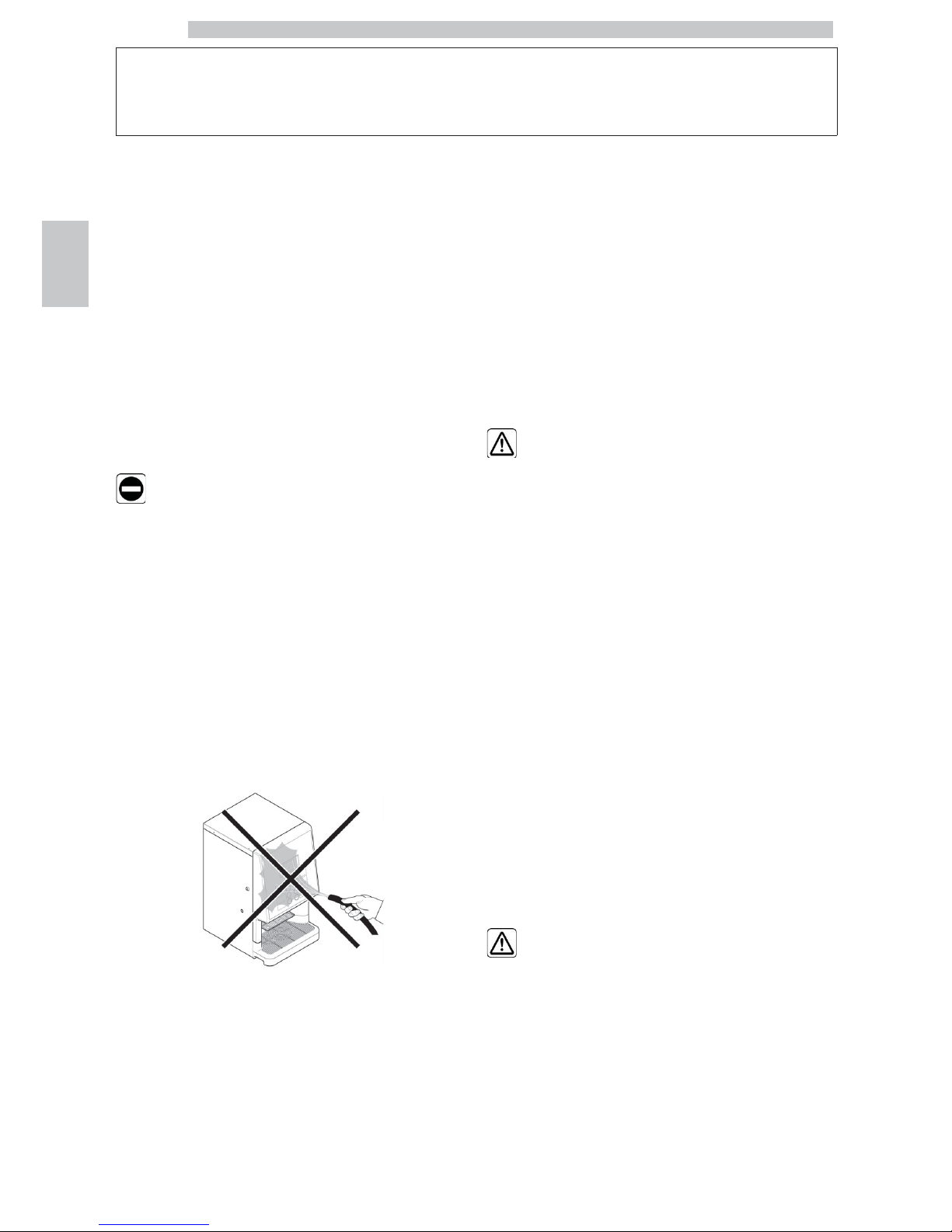
It is forbidden to: use jets of
water for cleaning operations.
The appliance is only to be
installed in locations where its
use and maintenance is
restricted to trained
personnel.
The use by children older
than 8 years or by persons
with reduced physical, mental
or sensory abilities or with lack
of experience and skills is
allowed, provided that they
are supervised or instructed
on how to use the appliance
correctly and that they
understand the hazards
involved.
Children must not play with
the appliance.
Children must not carry out
any cleaning and maintenance
operations without being
monitored.
Do not direct water jets on
the components and/or on
the vending machine.
Page 15
English
15
Before connecting the
appliance to water network,
please read and follow the
applicable regulations in force
in your country.
If the supply cord is damaged,
it must be replaced by the
manufacturer, its service agent
or similarly qualified persons in
order to avoid a hazard.
Connect the vending machine
to drinking water mains with
pressure between 0.15 MPA
and 0.8 MPA (1.5 and 8 bar),
see data on the label.
Access to the service area is
restricted to persons having
knowledge and practical
experience of the appliance, in
particular as far as safety and
hygiene are concerned.
Before performing any
maintenance and/or cleaning
operation, unplug the power
cord.
Page 16

English
16
CONTENTS
MAIN PARTS
2
1 INTRODUCTION TO THE MANUAL
17
1.1 PREAMBLE
17
1.2 ICONS USED
18
2 INFORMATION ON THE VENDING
MACHINE
19
2.1 INFORMATION FOR THE MAINTENANCE
TECHNICIAN
19
2.2 DESCRIPTION AND INTENDED USE
19
2.3 VENDING MACHINE IDENTIFICATION
20
2.4 TECHNICAL SPECIFICATIONS
21
3 SAFETY
22
3.1 PREAMBLE
22
3.2 GENERAL SAFETY INSTRUCTIONS
22
3.3 OPERATOR REQUIREMENTS
23
3.4 SAFETY DEVICES
23
3.5 RESIDUAL RISKS
24
4 HANDLING AND STORAGE
25
4.1 UNLOADING AND HANDLING
25
4.2 STORAGE
25
5 INSTALLATION
26
5.1 CAUTIONS
26
5.2 UNPACKING AND POSITIONING
26
5.3 LABEL APPLICATION
28
5.4 INSTALLATION OF PAYMENT SYSTEMS
31
5.5 CONNECTION TO WATER MAINS
32
5.6 CONNECTION TO THE ELECTRIC NETWORK
33
5.7 COFFEE GROUNDS DISCHARGE SETTING
33
5.8 LIQUID DRAIN SETTING
34
6 DESCRIPTION OF CONTROLS
35
6.1 DISPLAY
35
6.2 KEYPAD
35
6.3 BUTTON DESCRIPTION DURING NORMAL
OPERATION
35
6.4 CPU CARD KEYS
35
7 SUPPLY AND START UP
36
7.1 CONTAINER CONFIGURATION
36
7.2 INSTANT PRODUCT SUPPLY
39
7.3 COFFEE BEAN SUPPLY
39
7.4 FILLING THE WATER TANK
40
7.5 TOP DOOR INTERMEDIATE LOCKING
41
7.6 DOSE CALIBRATION
41
7.7 COFFEE GRIND ADJUSTMENT
42
7.8 FIRST START-UP OF THE VENDING MACHINE
42
7.9 WATER CIRCUIT FILLING
42
7.10 WASHING THE PARTS COMING INTO
CONTACT WITH FOOD
42
7.11 USE OF THE VENDING MACHINE
42
8 PROGRAMMING AND MAINTENANCE
MENU
43
8.1 KEY DESCRIPTION OF PROGRAMMING AND
MAINTENANCE PHASES
43
8.2 PROGRAMMING MENU
43
8.3 MAINTENANCE MENU
64
8.4 MACHINE READY / FREE BUTTON
68
9 OPERATION AND USE
69
9.1 BEVERAGE SELECTION
69
9.2 CAPPUCCINO WITH COLD MILK FUNCTION
70
9.3 WARNING SIGNALS
71
10 CLEANING AND MAINTENANCE
72
10.1 GENERAL NOTES FOR CORRECT
OPERATION
72
10.2 CLEANING AND SCHEDULED
MAINTENANCE
73
10.3 NON-SCHEDULED MAINTENANCE
83
10.4 SOFTWARE UPDATE
84
10.5 MANAGEMENT OF DEFAULT VALUES
85
11 TROUBLESHOOTING
86
12 STORAGE - DISPOSAL
88
12.1 LOCATION CHANGE
88
12.2 INACTIVITY AND STORAGE
88
13 INSTRUCTIONS FOR END OF
OPERATIONAL LIFE DISPOSAL
89
Page 17
English
1
17
1 INTRODUCTION TO THE MANUAL
1.1 Preamble
This publication is an
integral part of the vending
machine and must be read
carefully to ensure the
machine is used correctly
and in compliance with
essential safety
requirements.
This manual contains the
technical information
required for the correct
use, installation, cleaning,
and maintenance of the
vending machine.
Always refer to this manual
before carrying out any
operation.
Manufacturer: SAECO Vending S.p.A.
Località Casona, 1066 - 40041 Gaggio Montano
Bologna, Italy
This publication should be
kept carefully, together
with the vending machine
throughout its operational
life, even in case of changes
of ownership.
If this manual is damaged
or lost, a copy may be
requested from the
manufacturer or the
technical service by
indicating the data
contained on the data
plate on the rear side of
the vending machine.
Page 18
English
1
18
1.2 Icons Used
Various kinds of warnings are contained in this manual to
highlight the different hazard or competence levels.
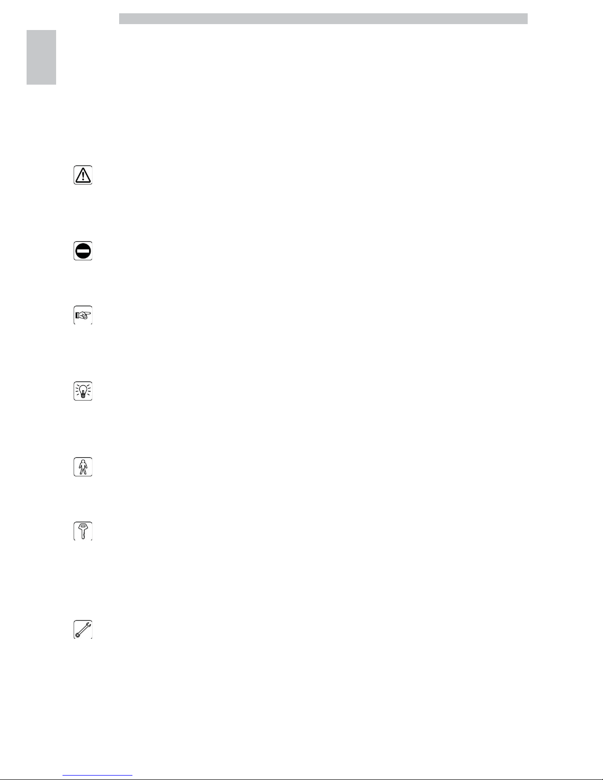
The symbol is integrated with a message suggesting use
procedures or actions and providing useful information for
the correct operation of the machine.
Warning
Indicates dangerous situations for the users, supply
operators and maintenance technicians dealing either with
the vending machine or the product to be dispensed.
Prohibition
It is used to highlight actions/operations not to be
performed.
Important
Indicates the operations for keeping the vending machine
in good working order.
Suggested solutions
It is used to indicate alternative procedures which make
programming and/or maintenance operations quicker.
User
Indicates the user of the vending machine. Users are not
allowed to perform any cleaning or maintenance
operations.
Supply operator
Indicates operations to be carried out only by personnel in
charge of supplying and cleaning the vending machine.
Supply operators can not perform any operations
requiring a Maintenance Technician.
Maintenance technician
It is used to signal those operations that must be
performed only by the specialised maintenance technicians.
The Maintenance Technician is the only person authorized
to keep the MICROSWITCH ENABLING KEY, by which
the security systems can be disabled.
Page 19
English
2
19
2 INFORMATION ON THE VENDING MACHINE
2.1 Information for the
Maintenance Technician
The vending machine must
be installed in a well-lit, dry
area, away from bad
weather and dust, on a
floor suitable to support its
weight.
To ensure its correct operation and reliability over time,
comply with the following recommendations:
• ambient temperature: from +2°C to +32°C;
• maximum humidity allowed: 80% (non-condensed).
For special installations, not covered by this manual, please
contact the dealer or the local importer. If this is not
possible, please contact the Manufacturer.
The technical service is available for any explanation or
information regarding the correct operation of the vending
machine and to satisfy any request for spare parts supply
or technical assistance.
The Maintenance Technician must carefully read and
observe the safety warnings contained in this manual to
ensure that installation, start-up, use and maintenance
operations are performed in complete safety.
It is the Maintenance Technician’s absolute responsibility
to give the keys to access the inside of the vending
machine to another operator (Supply Operator), provided
that the Maintenance Technician bears full responsibility
for all work carried out.
This manual is an integral part of the machine and must be
always read carefully before performing any operation.
2.2 Description and Intended Use
The vending machine is intended for automatic distribution of
coffee and hot beverages (decaffeinated coffee, cappuccino,
chocolate, etc.) and is programmable for every single type of
dispensing dosage. The instant products must be consumed
immediately, and cannot be preserved for a long time.
Using the machine for any other purpose is considered
dangerous and as a misuse.
Do not place any product
inside the vending machine
which may be dangerous as
a result of unsuitable
temperatures.
With reference to the definition of “professional appliance” given
by the standard EN60335-2-75 for vending machines, this
appliance can not be classed as professional.
Misuse voids all forms of
warranty, releasing the
Manufacturer from any
responsibility for damage to
property and/or personal
injury.
The following are also
considered misuse:
• any use other than the intended use and/or employing methods
other than those described in this manual;
• any intervention on the vending machine which differs from the
instructions given in this publication;
Page 20
English
2
20
• any tampering with parts and/or safety devices not previously
authorised by the Manufacturer and performed by unauthorised
personnel;
• any location of the vending machine not provided in this manual.
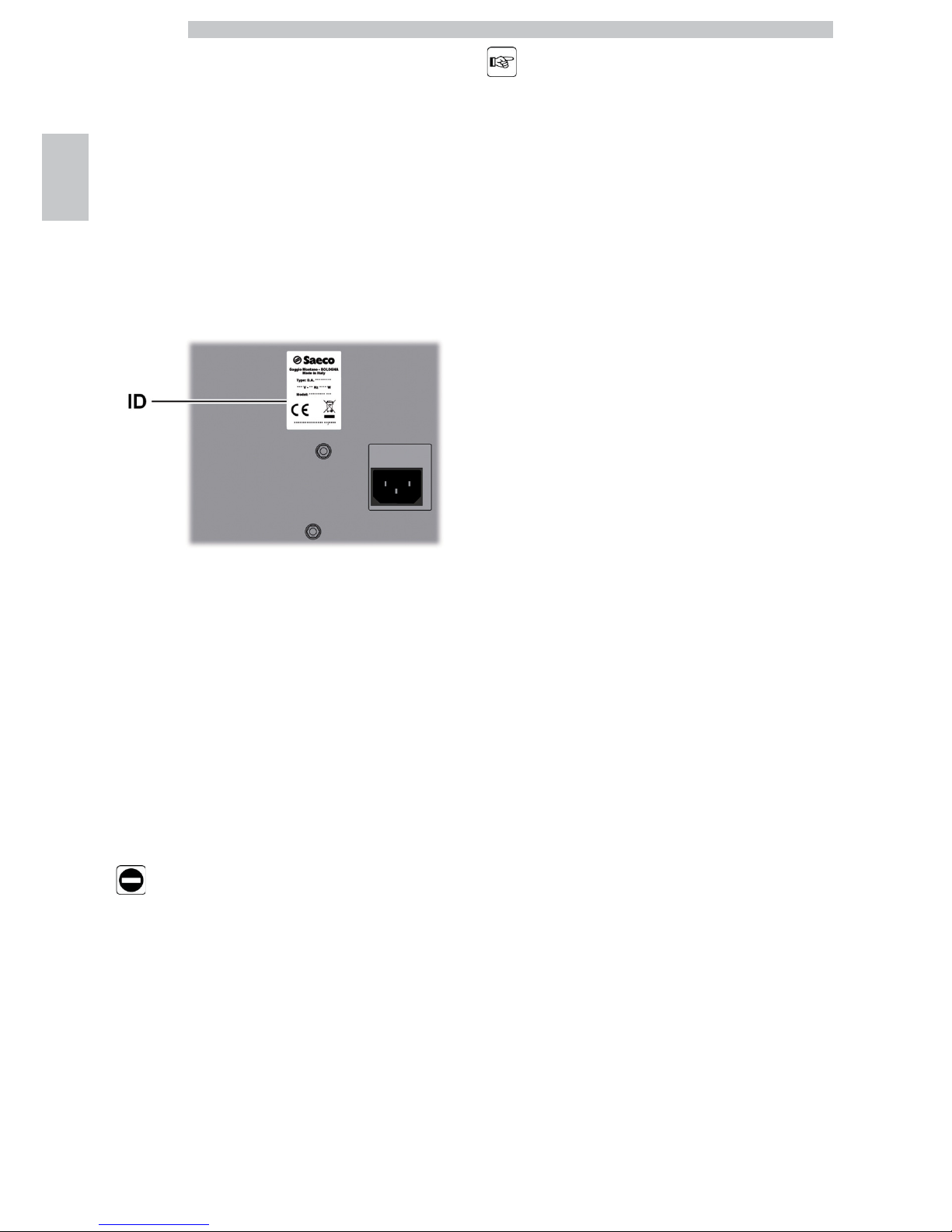
2.3 Vending Machine
Identification
The vending machine is identified by the name, model and serial
number which can be found on the relevant data plate.
ID Data plate
The plate contains the following data:
• name of the Manufacturer;
• marks of conformity;
• model;
• serial number;
• year and month of manufacture;
• supply voltage (V);
• supply frequency (Hz);
• electrical power consumption (W);
• VM Code
It is strictly forbidden to
tamper with or modify the
data plate.
When contacting the
technical service, always
refer to this plate by
indicating the technical
data shown on it.
Page 21
English
2
21
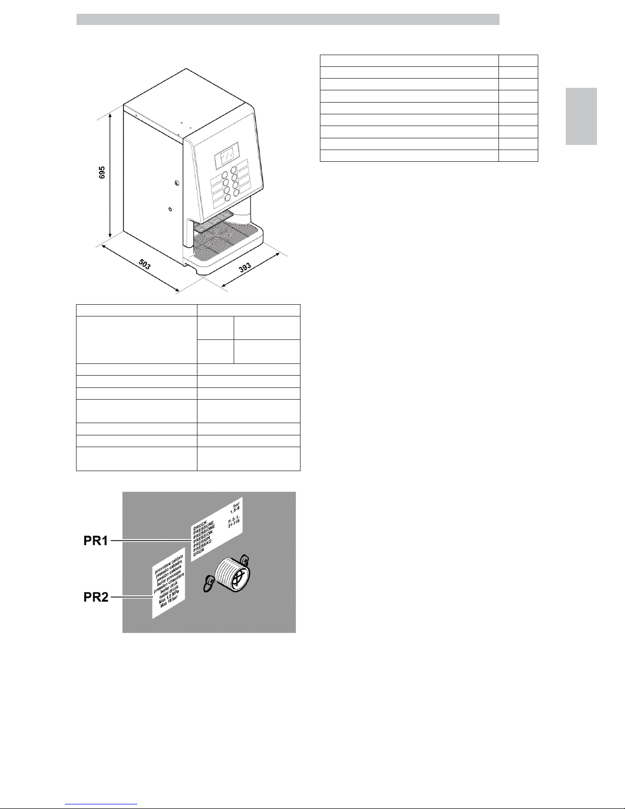
2.4 Technical Specifications
Size (w x h x d) 393 x 695 x 503 mm
Weight
36,5 kg Espresso model
37,5 kg
Cappuccino
model
Power consumption See the data plate
Supply Voltage See the data plate
Electric voltage frequency See the data plate
Power cord length 1600 mm
Water mains connection 3/4” Gas type
Water mains pressure See the data plate
A-weighted sound pressure level less than 70 dB
PR1
Data plate showing minimum and maximum water supply
pressure
PR2 Boiler pressure data plate
Container capacity
Coffee beans 1 kg
Hot Chocolate 1,75 kg
Milk 0,65 kg
Lemon tea 1,5 kg
Ground coffee 0,62 kg
Double Ginseng 1,85 kg
Standard Ginseng 1,15 kg
Standard Freeze-dried coffee 0,41 kg
Standard Barley 0,36 kg
Page 22
English
3
22
3 SAFETY
3.1 Preamble
In accordance with the applicable standards and
regulations, SAECO VENDING has prepared a technical
file relating to the PHEDRA EVO vending machine at its
premises, acknowledging the following standards in the
design stage:
- EN 55014 - EN 61000-4-4
- EN 6100-3-2 - EN 61000-4-5
- EN 61000-3-3 - EN 61000-4-11
- EN 61000-4-2 - EN 60335-2-75
- EN 61000-4-3 - EN 60335-1
3.2 General Safety Instructions
It is forbidden to:
• tamper with or disable the safety systems installed on the
vending machine;
• carry out maintenance on the vending machine without
unplugging it first;
• install the vending machine on the outside. It is advisable to place
it in a dry place where the temperature does not drop below
2°C, in order to prevent any possible freezing.
• use the vending machine for purposes other than those indicated
in the sale contract and in this publication;
• electrically connect the appliance using multi-sockets or adapters;
• use jets of water for cleaning operations.
It is mandatory to:
• check conformity of the power supply;
• use original spare parts;
• carefully read the instructions contained in this manual and in the
attached documents;
• use personal protective equipment when performing installation,
testing and maintenance operations.
• Use a new gasket kit every time you disconnect and then
connect again the machine to the water supply.
Precautionary measures to prevent human errors:
• make the operator aware of safety issues;
• handle the vending machine, either packaged or unpackaged, in
safe conditions;
• deeply know the installation procedures, its correct operation
and its limits;
• dismantle the vending machine in safe conditions, in accordance
with the environmental protection and health and safety laws in
force.
To prevent machining
residues from coming into
contact with the beverages,
dispense about 0.5 l of
water for each dispensing
path before definitely
starting the machine. The
dispensed beverages can
be drunk only after
performing this operation.
In case of failure or
malfunctioning, please refer
only to the qualified
personnel of the technical
service.
Page 23
English
3
23
The manufacturer is not
liable for damage to
persons or property
resulting from failure to
follow the safety
instructions provided in
this section.
3.3 Operator Requirements
Three operators with different skills are required in order
to guarantee the appliance’s safety:
User
Access to the internal part of the vending machine is
forbidden to the user.
Supply operator
The Maintenance Technician assigns the safekeeping of the
access key to the Supply operator who is in charge of
product supply, external cleaning, and starting up /
stopping of the vending machine.
The Supply operator is not
allowed to carry out
operations indicated in this
manual as competence of
the Maintenance
Technician.
Maintenance technician
The maintenance technician is the only person authorised to
service the machine, start the programming procedures and
perform the adjustment, set up and maintenance operations.
Access to the service area is
restricted to persons having
knowledge and practical
experience of the appliance,
in particular as far as safety
and hygiene are concerned.
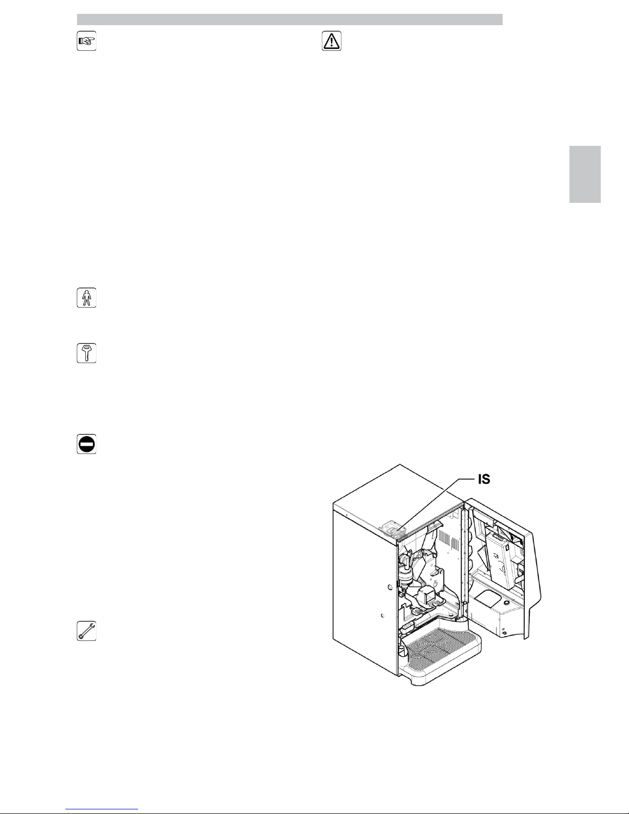
3.4 Safety devices
The vending machine is equipped with:
• a safety switch which cuts out the voltage to all the inside
components any time the front door is opened.
• A microswitch interrupts the dispensing of coffee products
when the coffee grounds tray is not correctly positioned.
A message indicating the incorrectly positioned part
appears on the display.
• A microswitch blocks vending machine operation when
the drip tray is not correctly positioned. A message
indicating the incorrectly positioned part appears on the
display.
• A sensor blocks vending machine operation when the drip
tray is full. The message "Empty water tank" is displayed.
IS Safety switch
Page 24
English
3
24
Maintenance technician
In case of programming or setting up operations only the
Maintenance Technician can intervene by inserting the
relevant key into the safety switch and resetting the
voltage even if the door is open.
This operation, necessary
for starting up the vending
machine, disables the safety
system.
It must therefore be
carried out by qualified
personnel (Maintenance
Technician) aware of the
risks resulting from the
presence of live or moving
components.
3.5 Residual Risks
Risk of burning if the hands
are placed inside the outlet
during beverage brewing.
Before removing the cup
from the outlet, please
wait for the message
“REMOVE CUP” on
display.
Before brewing a beverage
make sure that the
previous one has already
been picked up and that
the cup support is empty.
Page 25
English
4
25
4 HANDLING AND STORAGE
4.1 Unloading and Handling
Unloading and handling operations after transportation
must be carried out only by qualified personnel and using
suitable equipment.
The vending machine will be delivered in a package, so as
to ensure protection against any mechanical and
environmental agent.
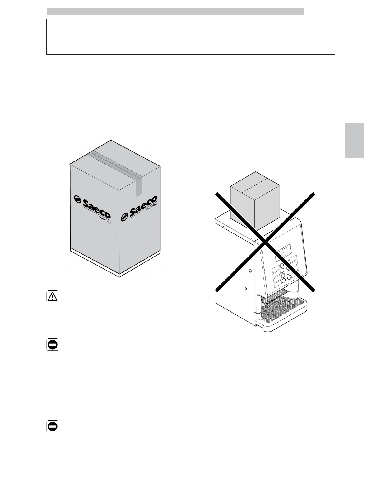
The vending machine must
always be kept in the
upright position.
Do not:
• dragging the vending machine;
• overturning or laying the vending machine flat during
transport and handling;
• shaking the vending machine;
• lifting the vending machine with ropes or cranes;
• leaving the vending machine exposed to the elements, in
humid areas or close to heat sources.
Avoid that:
• being bumped into
• being overloaded with other parcels
4.2 Storage
If the vending machine is not installed immediately, it
should be stored in a sheltered area, conforming to the
following instructions:
• the packaged vending machine must be stored in a closed,
dry area at a temperature between 1°C and 40°C;
• do not put other appliances or boxes on the vending
machine;
• it is always good practice to protect the vending machine
from any deposits of dust or other material.
Page 26
English
5
26
5 INSTALLATION
5.1 Cautions
The vending machine
cannot be installed
outdoors; avoid placing it
in areas where the
temperature is less than
2°C or more than 32°C
and in particularly dump or
dusty areas. It should
neither be installed in
places where water jets are
used for cleaning
operations nor where
there is a risk of fire or
explosion.
Make sure that the installation place is compatible with the
following specifications, before unpacking the appliance:
• the power socket must be located in an easily accessible
area, not more than 1.5 meters away;
• the socket voltage must correspond to that indicated on
the appliance data plate.
• the surface or floor must NOT have a gradient of more
than 2°.
The vending machine must
be installed on a flat
surface.
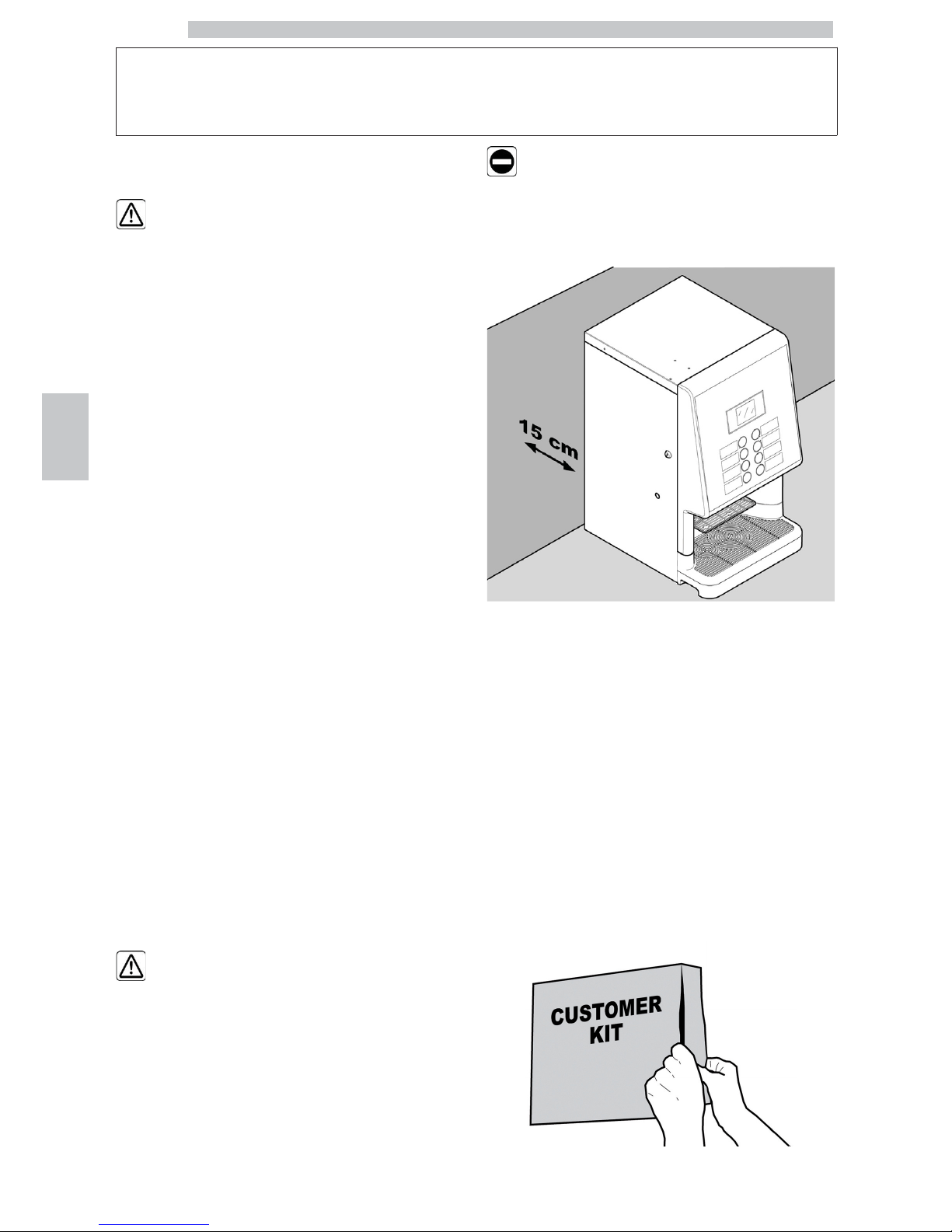
If the vending machine needs to be positioned close to a
wall, it is necessary to leave a space of at least 15 cm
between the back and the wall in order to keep the air
outlet grille free.
Under no circumstances
cover the vending machine
with cloths or similar.
5.2 Unpacking and Positioning
On receipt of the vending machine make sure that it has
not been damaged during transportation and that package
has not been tampered with or that internal parts have not
been removed.
A bag, called “CUSTOMER KIT”, is supplied with the
vending machine. It contains the following items:
• Instruction booklet
• Power cord
• Door safety microswitch disabling keys (Maintenance
Technician)
• Product labels and prices
Page 27
English
5
27
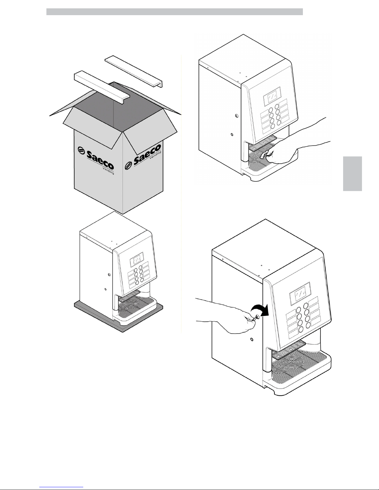
The vending machine is placed on a polystyrene base protected by two polystyrene corners, a polyethylene
foam sheet and a bag - and is delivered in a box.
If damage of any kind is found, the courier must be
informed and notice must be immediately given to the
importer or to the seller.
If these are not in the purchaser’s country, please contact
the manufacturing company directly.
Take the key from the dispensing outlet.
Insert the key into the lock, turn clockwise and open the
door.
Page 28
English
5
28
5.3 Label application
5.3.1 Product labels
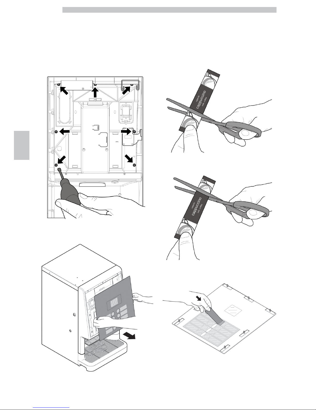
Open the door. Using a box spanner, unscrew the 7
keypad panel locknuts.
Remove the keypad panel.
Take out the product label sheet included in the customer
kit.
Remove the labels from the product label sheet by
following the pre-cut line.
Cut the labels as shown in the figure to make the left ones
or the right ones.
Left labels
Right labels
Insert the product labels in the keypad panel.
Page 29

English
5
29
Check the exact position of the labels against the selection
key. Insert the keypad panel back into place. Using a box
spanner, screw the 7 keypad panel locknuts to their limit
stop.
To make different labels from the ones provided in the kit,
please use the "Labels" module available on our web portal
"Saeco Vending Online" at www.saecovending-online.com.
For printing, we suggest using paper with the following
properties: 170-g matte coated paper.
Standard product configuration
Phedra Espresso 2 instant products
Phedra Espresso 3 instant products
Phedra Espresso Water Tank
Phedra Espresso T.T.T
Page 30

English
5
30
Phedra Cappuccino
Phedra Cappuccino Water Tank
Phedra Cappuccino T.T.T.
Page 31

English
5
31
5.4 Installation of Payment
Systems
The vending machine is designed for the installation of
various payment systems, such as:
- parallel validator 24 V DC
- executive systems (also PRICE HOLDING);
- MDB systems;
- BDV systems;
- cashless reader;
A coin validators
B cashless reader
The vending machine is
not supplied with any
payment system, which
must be installed by the
person in charge of its
fitting.
After the chosen payment
system has been installed,
the corresponding
parameters can be set
through the programming
menu (see section
“Programming menu”).
The Manufacturer declines
any liability for any damage
to the vending machine, to
property and/or injury to
persons, caused by the
installation of the payment
system. The responsibility
falls to the person who
carried out the installation.
Page 32

English
5
32
5.5 Connection to water mains
The pressure reducer is
calibrated during assembly.
Should problems occur
with the calibration of the
pressure reducer, the
outlet pressure value must
absolutely be reset to 0.8 –
1 bar max. Different or
approximate calibration
may cause product quality
and quantity variations
when brewed.
It is recommended to use
a descaling device for the
water network supplying
the vending machine,
especially for water with a
high calcium and
magnesium content (hard
water).
Connect the vending
machine to drinking water
mains with pressure
between 0.15 MPA and
0.8 MPA (1.5 and 8 bar),
see data on the label.
Before connecting the
appliance to water
network, please read and
follow the applicable
regulations in force in your
country.
Connect the water network hose (supplied with the
appliance) to the vending machine 3/4" Gas coupling.
The water mains pipe
should be certified
according to the standard
IEC 61770.
Page 33

English
5
33
The new hose-sets
supplied with the appliance
are to be used and that old
hose-sets should not be
reused.
5.6 Connection to the Electric
Network
The Maintenance Technician,
who is responsible for the
installation of the vending
machine, must ensure that:
• the power supply system complies with the safety instructions in force;
• the voltage corresponds to that indicated on the appliance data plate.
In case of doubt, do not
proceed with the installation
and ask qualified and
authorised personnel to
accurately check the system.
The vending machine is equipped with a power cord which must be
plugged into the appropriate socket on the vending machine back panel.
Do not use adapters or multi-sockets.
Make sure that the power
cord plug is easily reachable
after installation.
5.7 Coffee Grounds Discharge
Setting
The appliance is setup for direct discharge of the coffee grounds
into the bag in the dedicated cabinet or into another container
located below the appliance (ex. bar counter).
For this setting, the vending machine base must be cut along the
indicated marks.
The appliance has an alarm
signal to indicate when to
empty the coffee grounds
in the standard version. For
this setting it is necessary
to exclude this counter
using the menu.
Page 34

English
5
34
A Marks
Use the coffee grounds
conveyor C (optional) as
shown in the figure.
In case of placing the appliance on the top of a working
surface, in order to discharge the coffee grounds into a
container placed below , make a 75 mm Ø hole (minimum)
on the surface as shown in the figure. Install the machine in
its final position on the supporting surface (the rings P
indicate the ideal position of the adjustable feet).
FR Machine front side
F Hole to be made
P Ideal position of the adjustable feet
5.8 Liquid Drain Setting
The appliance is setup for direct drainage of the drip tray
into container in the dedicated cabinet or into another
container located below the appliance. To use this setting,
cut (or drill a hole in) the panel in the indicated area.
A diaphragm
Page 35

English
6
35
6 DESCRIPTION OF CONTROLS
6.1 Display
The display shows the messages during normal operation
and during the programming and maintenance phase.
6.2 Keypad
Each key function changes
according to the vending
machine mode (ordinary
dispensing or programming
mode).
Each key has a double
function that varies
according to the vending
machine status (standard
operation or programming).
6.3 Button Description during
Normal Operation
6.3.1 Set 1 Pre-selection button
The function connected to the button may be chosen from
the following options:
A. Beverage 5
B. Pre-selection of beverages 9-16
C. Disabled
6.3.2 Set 2 Pre-selection button
The function connected to the button may be chosen from
the following options:
A. Beverage 6
B. Pre-selection of beverages 17-24
C. Disabled
6.3.3 Keys (1 to 8)
By pressing these keys, the programmed beverages are
dispensed.
6.4 CPU card keys
The CPU electronic board is equipped with 3 buttons
which allow the Maintenance Technician to carry out the
programming and maintenance operations.
P1 Programming menu key
P2 Maintenance menu key
P3 Machine Ready / Free Button
Page 36

English
7
36
7 SUPPLY AND START UP
7.1 Container Configuration
7.1.1 Espresso Version
The containers delivered
are designed to dispense
the following products:
2 instant products 3 instant products
Instant pr. 1 not present Tea
Instant pr. 2 Milk Milk
Instant pr. 3 Hot Chocolate Hot Chocolate
Instant pr. 4 Coffee beans Coffee beans
7.1.2 Espresso Water Tank version
The containers delivered
are designed to dispense
the following products:
Instant pr. 1 not present
Instant pr. 2 Milk
Instant pr. 3 Hot Chocolate
Instant pr. 4 Coffee beans
Page 37

English
7
37
7.1.3 Espresso T.T.T. version
The containers delivered
are designed to dispense
the following products:
Instant pr. 1 Tea
Instant pr. 2 Milk
Instant pr. 3 Ground coffee
Instant pr. 4 Coffee beans
7.1.4 Cappuccino Version
The containers delivered
are designed to dispense
the following products:
Instant pr. 1 Freeze-dried coffee
Instant pr. 2 Barley
Instant pr. 3 Hot Chocolate
Instant pr. 4 Coffee beans
Instant pr. 5 Fresh milk container
Page 38

English
7
38
7.1.5 Cappuccino Water Tank
version
The containers delivered
are designed to dispense
the following products:
Instant pr. 1 not present
Instant pr. 2 Barley
Instant pr. 3 Hot Chocolate
Instant pr. 4 Coffee beans
Instant pr. 5 Fresh milk container
7.1.6 Cappuccino T.T.T. version
The containers delivered
are designed to dispense
the following products:
Instant pr. 1 Tea
Instant pr. 2 Hot Chocolate
Instant pr. 3 Ground coffee
Instant pr. 4 Coffee beans
Instant pr. 5 Fresh milk container
Page 39

English
7
39
7.2 Instant product supply
Open the vending machine front door. Open the top door.
Open the cover of the container to be supplied.
Pour the instant product into the container.
Close the container cover.
7.3 Coffee Bean Supply
Open the vending machine front door. Open the top door.
Remove the container cover.
Pour the coffee beans into the hopper.
Replace the cover on the container.
Page 40

English
7
40
If the message “NO MORE
COFFEE” is displayed, refill
the vending machine, turn
it off and then on again.
7.4 Filling the Water Tank
(For Water Tank version only)
Open the vending machine front door. Open the top door.
Remove the tank and place it under a water tap.
Fill the tank with tap water.
Put the water tank back in place.
An optional kit allowing to fill the water tank without
removing it from the vending machine is available.
Page 41

English
7
41
7.5 Top door intermediate
locking
The vending machine is provided with an intermediate
locking position for the top door in case, due to its
location, it cannot be completely opened.
Proceed as follows to lock the top door in the
intermediate position:
- Open the vending machine front door.
- Lift the door and press bracket A.
Slightly lift the door, pull bracket A and lower the door to
unlock the door.
7.6 Dose calibration
The vending machine is delivered with standard calibration
values set by the manufacturer.
Dose calibration can be performed by means of two
calibration levels:
• remove the cover;
• free the adjusting lever from the rack and put the internal
divider pulling peg into one of the 4 possible positions in
the basic coffee quantity area (7 gr - 8 gr - 9 gr - 10 gr);
• move the adjusting lever into the rack and select the slot
corresponding to the dose required.
Page 42

English
7
42
7.7 Coffee Grind Adjustment
Turn the ring until the required results are obtained.
After any calibration three selections are necessary before
the new setting becomes effective.
7.8 First start-up of the vending
machine
Supply the vending machine (following the instructions
given previously) and plug it into the power supply (see
section "Power Grid Connection").
At this point the message “PHEDRA EVO” will appear on
the display and the self-diagnosis phase is activated to
check the correct positioning of the machine devices.
Any faults detected during the self-configuration cycle are
stored so that the vending machine can display them at the
end of the self diagnostic phase.
Carry out the grinder adjustment as indicated in the
instructions at section "Coffee Grinder Adjustment" after
refilling the water circuit.
7.9 Water circuit filling
At first VM start-up, the boiler is filled automatically.
7.9.1 Filling the boiler manually
After switching the vending machine on it is possible to fill
the boiler by activating the following procedure:
Procedure A
• press the P2 key to enter the maintenance menu;
• Enter the Maintenance/Washes menu and start the
automatic washing cycle;
Procedure B
• press the P2 key to enter the maintenance menu;
• Enter the Maintenance/ Boiler Refill menu and start the
automatic refill cycle;
The rinsing operation must
be repeated until water
flows out of the brewing
nozzles regularly.
7.10 Washing the Parts coming
into Contact with Food
Clean all the parts of the VM which are in contact with
foodstuffs.
• Thoroughly wash your hands.
• Prepare a chlorine-based, antibacterial disinfecting solution
(the products can be purchased at the chemist's) following
the concentrations indicated on the product.
• Remove all the product containers from the vending machine.
• Remove the container lids and product chutes. Immerse
all these parts in the previously prepared solution.
7.11 Use of the vending machine
The beverage selection modes are indicated in chapter
"Operation and Use".
Page 43

English
8
43
8 PROGRAMMING AND MAINTENANCE MENU
This section illustrates how
to set up or modify the
vending machine
programming and
maintenance settings.
Therefore it is necessary to
carefully read it and to
understand the exact
sequence of operations
before performing them.
8.1 Key description of programming
and maintenance phases
To scroll through the vending machine menu, the keys
described below are used.
“e” Key: ENTER
By pressing this key it is possible to enter the following
programming or maintenance level. It is also possible to
modify or confirm the values set in the entries of the
programming or maintenance menus.
“c” Key: CANCEL
By pressing this key it is possible to go back to the
previous level of the programming or maintenance menu.
It is also possible to avoid storing the previously modified
values.
“v” Key: DOWN
Pressing this key it is possible to access the previous entry
inside the same level. If used after a setting modification
request, the value of this setting decreases.
“^” Key: UP
By pressing this key it is possible to access the next entry
inside the same level. If used after requesting the change of
a setting, the value of this setting increases.
8.2 Programming Menu
The structure of the programming menu is indicated in
section "Structure of the Programming Menu".
The section "Description of Messages in the Programming
Menu" describes all the items in the programming menu.
8.2.1 Access to the Programming
Menu
Open the door, disable the safety device (see section
“Safety Devices”) and press the P1 key to enter the
programming menu.
If no password has been assigned, the programming menu
is entered directly.
Page 44

English
8
44
If a password was assigned
to the vending machine to
enable the programming
menu, the message
"PASSWORD 000000" will
appear on the display with
a flashing cursor on the
first digit.
Now the password should
be entered using the UP
and DOWN keys. Confirm
the digit entered by
pressing the ENTER key.
Proceed as follows to exit the programming menu and
return to standard operation of the vending machine:
• Press the CANCEL button repeatedly until "EXIT ?"
appears. Select YES and press ENTER;
• remove the key from the safety switch in order to turn off
the vending machine;
• close the door and wait for the self-configuration process
to end.
Page 45

English
8
45
8.2.2 Structure of the
Programming Menu
ITEM NO. MENU ITEM
1. SYSTEM MANAGEMENT
1.1. VM Code
1.2. Stops *
1.2.1. Stop coffee C
1.2.2. Stop Pre-ground *
1.2.3. Stop beverages
1.2.4. CofGrounds contr. *
1.2.5. Stop CofGrounds *
1.2.6. Reset
1.3. Water Filter *
1.3.1. Last filter change
1.3.2. Remaining qty
1.3.3. Filter limit
1.3.4. Filter reset
1.3.5. Filter enabled
1.4. Temp. Boilers
1.4.1. Boiler 1 temp.
1.4.1.1. Min. Temperature
1.4.1.2. Max. Temperature
1.4.2. Boiler 2 temp.
1.4.2.1. Temperature
1.5. Energy save
1.5.1. Stand-by timeout
1.5.2. Eco timeout
1.5.3. Delta temp. Eco
1.6. Rinsing cycle *
1.6.1. Automatic
1.6.2. Programmable
1.7. Steam Cleaning
1.7.1. Steam Cleaning Time
1.7.2. Enable Capp. Clean.
1.8. Preheating
1.8.1. Coffee Preheat.
1.8.1.1. Operation after(min)
1.8.1.2. Extra Coffee Dose
1.8.2. Cappuccino Preheat.
1.8.2.1. Extra Time
1.8.2.2. Warm-Up T-Out
1.9. EV Water Assign *
1.10. Clock *
1.10.1. Time *
1.10.2. Date *
1.10.3. Date/time format *
1.11. On/Off time *
1.11.1. On 1
1.11.2. Off 1
1.11.3. On 2
1.11.4. Off 2
1.12. Audit Msg. Enable *
1.13. Water compensation
1.13.1. Beans
1.14. Lighting Type
1.15. Grouping Powders
1.15.1. Enable
1.15.2. Grouping Powders
1.16. Pre-grinding
1.17. Display settings
1.17.1. Brightness
1.18. Pulse counter *
1.19. Multiple beverage *
1.19.1. Multiple beverage
1.19.2. Enable Mult. bev.
1.19.3. Free *
1.20. Enable reset *
1.21. Buttons *
1.21.1. Button P3 *
1.21.1.1. Free vend key *
1.21.1.2. Free or Test *
1.22. Set 1 Pre-Selection
1.23. Set 2 Pre-Selection
1.24. Programmable texts *
1.24.1. Dispensing
1.24.2. Out of service
1.24.3. Set1 Pre-selection
1.24.4. Set2 Pre-selection
1.24.5. Default messages
1.25. Audit Device
1.25.1. Protocol
1.25.2. EA1..2 (Events)
1.25.3. EA3..5 (Readouts)
1.25.4. LA1-Prices Lists
1.25.4.1. LA1 Normal Prices
1.25.4.2. LA1 Diff1 Prices
1.25.4.3. LA1 Diff2 Prices
1.25.4.4. LA1 Card Prices
1.25.4.5. LA1 Free
1.25.4.6. LA1 Test
1.25.5. PA - Products
1.25.5.1. PA2
1.25.5.2. PA7
1.25.6. VA1..3 Sales
1.25.7. BA1-CA15-Cash
1.25.8. DA1..7-CashLess
1.25.9. Quick Reading
1.25.10. Extended Time-outs
1.26.-5 Tube emptying time *
1.27. Change Password *
1.27.1. Password prog.
1.27.2. Service Password
1.28. Complete menus
1.29. Drip Tray warning
1.30. Default Menu *
1.30.1. Factory default
1.30.2. Custom Default
1.30.2.1. Read Custom Default
1.30.2.2. Write Custom Default
1.31. VM Model *
1.32. Language
1.33. System Info
2. PAYMENT SYSTEMS
2.1. Protocol
2.2. Coin validator
2.2.1. Enable
2.2.2.-9 Coin Values
2.3. Banknote validator
2.3.1. Enable
2.3.2. INHIBITION LEVEL
Page 46

English
8
46
ITEM NO. MENU ITEM
2.3.3.-6 Banknote Value
2.3.3.4. Banknote
2.4. MDB settings *
2.4.1. Recharge enabled
2.4.2. Max Card Recharge
2.4.3. Max Card Value
2.4.4.-8 Coins Enabling
2.4.5. Alt. payout
2.4.6. Max change
2.4.7. Exact change policy
2.4.8. Min Tube Level
2.4.9. Manual Tube Filling
2.4.10. Manual Tube Empty
2.4.11. Commit to vend
2.4.12.-2 Bill Enabling
2.4.13. Bill Escrow
2.4.14. MDB Slave Address
2.4.15. no change =no bills
2.5. Max credit
2.6. Multivend
2.7. Overpay Time
2.8. Fixed Zeroes *
2.9. Decimal Digits *
2.10. Credit Wdog *
2.11. Preselection
2.11.1. Pre-selection Time
2.12. Cash sale cmd sending
2.13. (EXE/PHD) safe mode
3. PRODUCT SETUP
3.1.-2 Product Before *
3.2. Beverage Enabling *
3.3. Beverage Preparation
3.3. Sequence
3.3. H2O / Coffee
3.3. Steam Duration
3.3. Freshbrew Water
3.3. Pre-ground Water
3.3. Fresh inst. time
3.3. Pre-gr.inst.time
3.3. Just water
3.3. % instant product #:
3.3. % pump #:
3.3. Instant prod. dose #:
3.3. Inst. prod. water #:
3.3. Beverage test
3.4. Prebrewing
3.4.1. Prebrewing [ml]
3.4.2. Pre-brew. pause[s/10]
3.5. Beverage interruption
3.6. Ingredient management
3.6.1. Enable
3.6.2. Read from USB KEY
3.6.3. Display
3.6.4. Write on USB KEY
4. SALE MANAGEMENT
4.1.-8 Price table
4.2. Beverage price
4.2.1. Normal
4.2.1.1. Global price
4.2.1.2. Single Prices
4.2.2. Differentiated 1 *
4.2.2.1. Global price
4.2.2.2. Single Prices
4.2.3. Differentiated 2 *
4.2.3.1. Global price
4.2.3.2. Single Prices
4.2.4. Card *
4.2.4.1. Card Prices
4.2.4.2. Global price
4.2.4.3. Single Prices
4.3. Free
4.4. Free On
4.5. Free Off
4.6. Diff Prices 1-On
4.7. Diff Prices 1-Off
4.8. Diff Prices 2-On
4.9. Diff Prices 2-Off
(*) = Visible only if complete menus are enabled.
Page 47

English
8
47
8.2.3 Description of Messages in the Programming Menu
DISPLAY Description
1. The SYSTEM MANAGEMENT items are:
SYSTEM MANAGEMENT
…
1.1. Enables an identification code to be assigned to the vending machine.
VM Code
531000
1.2.
Enables setting of the maximum amount of beverage or coffee.
Once the maximum amount is reached, the vending machine stops dispensing the relevant beverages.
The first digit on the left (“00000”) refers to the quantity of product dispensed since the last “RESET” (partial
counters).
The right hand digit, preceded by “LIM”, shows the maximum dispensable quantity (value may be modified).
Stops
…
1.2.1. Enables setting of the maximum number of coffee cups to be dispensed before the stop.
Stop coffee C
1.2.2.
It allows setting the maximum number of pre-ground product servings to be brewed before
stopping the pre-grinding.
Stop Pre-ground
1.2.3. Enables setting of the maximum number of beverages to be dispensed before the stop.
Stop beverages
1.2.4.
Enables or disables control of the number of grounds discharged into the coffee grounds drawer.
When set to “YES” the machine will allow a certain number of cups of coffee to be brewed before
requiring the drawer to be emptied (see “STOP COFGROUNDS”).
When set to “NO” the machine will not control the number of grounds discharged into the drawer.
CofGrounds contr.
1.2.5.
It allows you to set the maximum number of coffee cups to be brewed, corresponding to
maximum dump box capacity.
Once reached the set quantity, coffee-based beverages dispensing is stopped.
Five cups of coffee before the lock is engaged, a blinking message appears on the display,
“EMPTY COFGROUNDS”.
Important
This lock can be reset by removing the coffee grounds drawer for at least 10 seconds.
Suggested solutions
It is advisable to set a max. of 30 coffees when using the dump box supplied with the
machine.
Important
Do not set any stop value if you are using the machine together with the supporting cabinet,
which is equipped with its own dump box which is not controlled electronically.
Stop CofGrounds
1.2.6. Enables resetting of all partial counters relative to product quantity stop functions.
Reset
1.3. Allows the use of the water filter to be checked.
Water Filter
…
1.3.1. Date of the last filter reset.
Last filter change
31.01.2008
1.3.2.
Number of litres of water that can still be dispensed before the filter needs to be
regenerated.
When this value is less than 1, a Warning (W83) is recorded in the Error LOG.
Remaining qty
95
1.3.3. Number of litres of water that can still be dispensed from the filter.
Filter limit
100
Page 48

English
8
48
DISPLAY Description
1.3.4.
Select YES to indicate a new filter has been installed
This operation returns “Remaining Qty” to the same value as “Filter Limit” and the date in
the “Last Filter Change” is changed to today’s date.
Filter reset
1.3.5.
Enables management of the "Remaining Qty" countdown.
Important
From the maintenance menu (button P2 on the CPU), you can access "Water Filter", "Last
Filter Change", "Remaining Qty" and "Filter Reset".
Filter enabled
yes
1.4.
According to the model, the Phedra vending machine may be equipped with 1 or 2 boilers.
The following "BOILERS TABLE" matches the boilers with the vending machine models.
Temp. Boilers
1.4.1. This menu option allows setting the operating temperature of boiler 1.
Boiler 1 temp.
1.4.1.1.
It allows you to set the temperature that the vending machine keeps for a few minutes after
a beverage has been brewed.
The set value is expressed in centigrade.
Min. Temperature
00
1.4.1.2.
It allows you to assign the temperature to which the vending machine is brought after a
certain time from the last dispensing, so that the natural lowering of the temperature of the
hydraulic circuits can be compensated.
The set value is expressed in centigrade.
Max. Temperature
000
1.4.2. This menu option allows setting the operating temperature of boiler 2.
Boiler 2 temp.
1.4.2.1.
It allows you to set the temperature that the vending machine keeps for a few minutes after
a beverage has been brewed.
The set value is expressed in centigrade.
Temperature
00
1.5.
The “Stand-by” and “ECO” modes allow reducing the energy consumption of the machine.
It is possible to select one or both modes.
Energy save
…
1.5.1.
The “Stand-by” mode is activated after some minutes of inactivity which can be set by
means of this menu option. By setting it to zero the function is disabled.
When the "Stand-by" mode is activated the coffee and steam boilers are off and the display
shows the message "Stand by".
To exit the “Stand-by” mode, press any button or insert some credit.
When normal operation is restored, the boilers are turned on and the vending machine
starts the warm-up phase.
Stand-by timeout
1.5.2.
The “ECO” mode is activated after some minutes of inactivity which can be set by means of
this menu option. By setting it to zero the function is disabled.
In “ECO” mode, the target temperature of the boiler is reduced by a preset value (see the
following menu option).
The vending machine remains in its “Ready” status and no message is shown to the user.
To exit the "ECO" mode, press any button or insert some credit.
When "ECO" mode is deactivated, the target temperature for boiler 2 is restored and the
machine starts the warm-up phase.
Eco timeout
1.5.3.
Allows to set by how many °C the steam boiler temperature must be reduced during the
“ECO mode” phase.
Delta temp. Eco
1.6. It allows enabling of the automatic rinsing of the mixing bowls.
Rinsing cycle
yes
1.6.1.
The automatic rinsing is performed as follows: the first rinsing takes place 10 minutes after
the “machine ready” status; if necessary, other rinses occur 7 hours after the last dispensing.
Automatic
Page 49

English
8
49
DISPLAY Description
1.6.2.
Programmable
1.7.
In case the steam circuit remains inactive for some hours (to be set under the option
“Steam Cleaning Time”) the vending machine will not allow brewing any beverages with
steam (under the letter “S” in the product list) unless a cleaning cycle is activated.
The message “NO Cappuccino” will be displayed (by setting the number of hours to zero
the cleaning message and the stop status will be disabled).
The cycle can be activated in the “Maintenance” menu as well as during normal operation of
the machine through the user cycle.
Activation using the menu:
Select the option “Steam Cleaning“ in the “Maintenance” menu.
Activation during normal operation:
The machine must comply with the following:
1 - Vending machine in its “Ready” status.
2 - No brewing in progress.
3 - Option “Enable Steam Wash” in the “System Management” menu enabled.
To activate the cycle simply press the buttons corresponding to beverages 4 and 8
simultaneously.
Cycle description:
The cycle operation is independent from the activation mode (no matter if started or not
from the “Maintenance” menu) and it consists of two phases: the “Wash Cycle” and “Rinse
Cycle”.
During the first phase, a display message will request to pour the mix of water and cleaning
solution (about 400 gr of water and Saeco compound).
Simultaneously press the buttons corresponding to beverages 4 and 8 to start the “Wash
Cycle”.
This phase will last 75 seconds, then the machine will pass to the following one.
During the second phase, a display message will request to insert only the water container
(about 400 gr of water).
Simultaneously press the buttons corresponding to beverages 4 and 8 to start the “Rinse
Cycle”.
This cycle will last 75 seconds.
At the end of this procedure, the cleaning cycle will be considered as completed and the
Cappuccinatore as cleaned, thus enabling brewing beverages with milk.
Steam Cleaning
1.7.1.
It refers to the circuit of the Cappuccinatore: it allows setting the interval (in hours) after
which a cleaning cycle of the circuit is requested.
Steam Cleaning Time
1.7.2.
If set on YES, it allows starting the cleaning cycle by simultaneously pressing the two
beverage buttons 4 and 8.
This allows executing a cleaning cycle on the circuit of the Cappuccinatore without the need
to open the machine.
Enable Capp. Clean.
1.8.
Allows setting timing and amounts for preheating and precooling for instant product circuits
and for the coffee brew group.
Preheating
00
1.8.1. Settings for the preheating cycle of the brew group.
Coffee Preheat.
1.8.1.1.
Time (expressed in minutes) of brew group inactivity after which the group starts
preheating.
By setting it to 0, the preheating is disabled.
Operation after(min)
1.8.1.2.
Increase in the water dose (in ml) for the first coffee (by first coffee we understand the
coffee for which the preheating of the brew group is activated).
Extra Coffee Dose
1.8.2.
It refers to the circuit of the Cappuccinatore: it allows setting the minutes of inactivity after
which a preheating cycle is requested before dispensing steam (by setting this value to zero
the preheating cycle is disabled).
This cycle improves the operation of the Cappuccinatore after a long period of inactivity.
Cappuccino Preheat.
00
Page 50

English
8
50
DISPLAY Description
1.8.2.1.
Extra time (in tenths of seconds) for steam dispensing applied in case the circuit is cold, since
a reduced quantity of milk is dispensed in this case.
Extra Time
00
1.8.2.2.
It determines the delay time (in minutes) after which the preheating of the Cappuccinatore
is enabled.
Warm-Up T-Out
00
1.9.
By setting the “W” value in the product list, hot water will be dispensed.
This menu allows choosing the solenoid valve to be used for dispensing
If the “hot water solenoid valve” kit is installed, set the value to 0 (zero) or select the
solenoid valve operating on the desired circuit among the available ones.
EV Water Assign
…
1.10. Enables setting of the hour, minute, day of the week, day of the month, month and year.
Clock
…
1.10.1.
Time
08:00
1.10.2.
Date
1.10.3. Enables date and time display in US format - enables temperature display in °F
Date/time format
1.11.
Allows setting the vending machine’s automatic on and off time ranges over the course of a
week.
On/Off time
…
1.11.1.
On 1
00:00
1.11.2.
Off 1
00:00
1.11.3.
On 2
00:00
1.11.4.
Off 2
00:00
1.12.
It allows displaying for a few seconds the selection counters (total and since last reset)
during the machine start-up phase.
Audit Msg. Enable
Page 51

English
8
51
DISPLAY Description
1.13.
Water compensation for coffee beverages.
The exact quantity of water dispensed by each machine depends on the construction
tolerances of each water circuit component (pump, flowmeter, tubes, etc.).
This menu allows you to set a correction "evening out" these differences so that the end
result in the cup is always the same even if the machine is different.
During manufacturing, the optimum value is calculated and stored for each vending machine.
If a FACTORY DEFAULT is carried out or the CPU board is replaced, you need to reset
the correct value by following the simple instructions here below:
• Set the water for the COFFEE beverage = 30
• Dispense 3 beverages, checking their weight and calculating the rounded-up mean value
• If the result obtained is higher or lower than 30, the excess/default value must be
subtracted/added from/to the value set by default
EXAMPLE:
BEVERAGE 1 SEQUENCE 000C
COFFEE WATER = 30
Coffee 1 = 32 g
Coffee 2 = 35 g
Coffee 3 = 28 g
Work out the mean:
32 + 35 +28 = 95 -> 95/3 = 31.6
In this case, 31.6 being the obtained value, the machine is dispensing more water than the
set amount, so you will need to subtract 2 from the value set in the BEANS
COMPENSATION menu
If the mean value obtained were 28, you should add 2 to the value set in the BEANS
COMPENSATION menu
Water compensation
1.13.1. Allows you to select the water compensation for products made from coffee beans
Beans
1.14.
It allows selecting the lighting mode of the dispensing outlet.
The options are:
Never, Always, beverage dispensing, beverage end.
Lighting Type
1.15.
It enables creating a group of 2 instant product containers.
The groups of containers can be used when a higher capacity of instant powder is required for a particular product
(e.g. when chocolate is largely used in a certain location, 2 chocolate powder containers can be dedicated
accordingly).
The machine software will be responsible for alternatively starting the two powder motors, to guarantee equal
product consumption in the 2 containers.
To use the instant product groups proceed as follows:
enter the System Management through the Groups option
enable groups management
select the pair of containers you would like to group together
programme the beverage recipe by introducing one of the 2 instant products that have been grouped.
Grouping Powders
1.15.1. Enables the instant product containers groups
Enable
1.15.2. Choosing the powder motor pair to be grouped together
Grouping Powders
1.16. Enables instant pre-grinding of the coffee dose.
Pre-grinding
yes
1.17. Display settings
Display settings
Page 52

English
8
52
DISPLAY Description
1.17.1. It allows adjusting the display brightness.
Brightness
1.18.
Enables selection of whether the 24 V dc electromechanical pulse counter (optional - to be
connected to the CPU card) has to count the coffees or all dispensed beverages.
Pulse counter
Coffee
1.19.
Allows selecting which beverages will be enabled for multiple brewing and the number of
brewings.
Multiple beverage
…
1.19.1. number of brewing procedures for multiple brewing
Multiple beverage
000
1.19.2. Allows selecting which beverages will be enabled for multiple brewing
Enable Mult. bev.
1.19.3. enables the free-of-charge dispensing of the multi beverage
Free
1.20. It allows enabling of the “RESET” for data in the statistics maintenance menu.
Enable reset
no
1.21. button settings
Buttons
…
1.21.1. Menu for setting the function of the P3 button
Button P3
no
1.21.1.1. Allows you to enable the P3 button on the CPU board during normal operation.
Free vend key
no
1.21.1.2.
Allows you to choose whether to associate the P3 button on the CPU board to free
product dispensing or to test product dispensing
Free or Test
1.22.
The function connected to the button may be chosen from the following options:
A. Beverage 5
B. Set 1 Pre-selection
C. Disabled
A - Beverage button 5:
this is the default function.
Button 9 functions as a regular button.
B - Set 1 pre-selection: by choosing this function, the button becomes a pre-selection button for the 9-16 beverage
set.
When pressed, the vending machine shows the pre-selection message on the display (“ DECAFF ” as default) and
makes the new beverage group available.
C Disabled: pressing the key has no effect.
Set 1 Pre-Selection
…
1.23.
The function connected to the button may be chosen from the following options:
A. Beverage 6
B. Set 2 Pre-selection
A - Beverage button 10:
this is the default function.
Button 6 functions as a regular button.
B - Set 2 pre-selection: by choosing this function, the button becomes a pre-selection button
for the 17-24 beverage set.
When pressed, the vending machine shows the pre-selection message on the display (“
BARLEY ” as default) and makes the new beverage group available.
Set 2 Pre-Selection
…
1.24.
Programmable texts
…
Page 53

English
8
53
DISPLAY Description
1.24.1.
it allows setting the message appearing on the display when the vending machine is
dispensing a product.
Dispensing
1.24.2. It enables setting the text on the display when the vending machine stops due to a fault.
Out of service
1.24.3.
Allows you to set the message appearing on the display when the pre-selection mode of
button 5 is activated for beverages 9-16.
Set1 Pre-selection
1.24.4.
Allows you to set the message appearing on the display when the pre-selection mode of
button 6 is activated for beverages 17-24.
Set2 Pre-selection
1.24.5.
It allows bringing the programmable messages back to their pre-set default value (this is
useful when changing the language is required).
Default messages
1.25.
It allows selecting the protocol to be used for transferring data from the VMC (DDCMP o
DEX) and which data category has to be transferred during an audit session.
Audit Device
…
1.25.1.
Protocol
1.25.2.
EA1..2 (Events)
1.25.3.
EA3..5 (Readouts)
1.25.4.
LA1-Prices Lists
1.25.4.1.
LA1 Normal Prices
1.25.4.2.
LA1 Diff1 Prices
1.25.4.3.
LA1 Diff2 Prices
1.25.4.4.
LA1 Card Prices
1.25.4.5.
LA1 Free
1.25.4.6.
LA1 Test
1.25.5.
PA - Products
1.25.5.1.
PA2
1.25.5.2.
PA7
Page 54

English
8
54
DISPLAY Description
1.25.6.
VA1..3 Sales
1.25.7.
BA1-CA15-Cash
1.25.8.
DA1..7-CashLess
1.25.9. Delete value = 0 data from EVA-DTS report
Quick Reading
1.25.10. Prolongation of response waiting time from EVA-DTS data players
Extended Time-outs
1.26.-5
Allows setting a delay between the end of beverage preparation and the display of the
"Remove cup" message to the user.
Such delay is necessary to allow a complete drainage of the liquid in the dispensing tubes.
Tube emptying time
1/5
1.27.
Enables setting of a password or modification of the current one.
The password consists of a number between 000001 and 999999.
The 0000 value (default value) means no password.
To set the password, press the UP and DOWN keys and confirm using the ENTER key.
Change Password
1.27.1. Allows setting a password to access the programming menu.
Password prog.
1.27.2.
Allows setting a password to access the maintenance menu.
Important
If the password is lost, you will have to contact the Saeco Vending Technical Assistance
Service to regain access to the Programming Menus.
Service Password
1.28.
Enables selection of whether the entries of the programming menu should be shown fully or
only partially.
Complete menus
1.29.
It allows to select the VM's operation in case the sensor detects that the maximum level in
the drip tray has been exceeded.
Machine block:
the VM does not allow to dispense beverages if the tray is full;
Message Only:
a display message is shown but it is possible to dispense beverages (WARNING failure to
empty the tray can lead to water coming out from the machine);
DISABLED: the sensor is not being used (WARNING failure to empty the tray can lead to
water coming out from the machine);
Drip Tray warning
1.30.
Management of default values for machine configurations.
The user can create and recall his own configuration.
Default Menu
1.30.1.
It allows reverting the programmable parameters to factory preset values.
This operation does not reset the product counter.
Factory default
1.30.2. Management of the configuration which has been created by the user
Custom Default
1.30.2.1. Restoring the configuration which has been saved by the user on the machine
Read Custom Default
1.30.2.2. Saving the user machine configuration
Write Custom Default
Page 55

English
8
55
DISPLAY Description
1.31.
It allows selecting the current model of the vending machine.
The vending machine model is specified on the label located inside the right side panel.
VM Model
1.32.
It allows to select the language to be used by the machine.
The available languages are:
Italian, English, French, German, Spanish, Portuguese, Dutch, Turkish, Russian, Polish,
Norwegian, Swedish, Finnish and Danish.
The machine texts can be modified according to the user’s needs to add new languages not
included in the default list.
(Contact the Customer Service for any information).
Language
1.33.
"This option allows you to access a page showing the overall machine configuration.
The display shows the following information:
First line: sw version (""x.yy.zz"" format) / program CRC (""abcd"" format)
Example: ""'SW v1.02.12/087c""
Second line: Boot loader version (""xx"" format) and name of the file searched for by the
boot loader on the USB key ("".s19"" extension not displayed)
Example: ""Boot 08SAE_DA5P""
Third line: memory version (""xxx.yyy."" format) and content CRC (""zzz"" format)
Example: ""Mem 123.456.789"""
System Info
2. The entries of the PAYMENT SYSTEMS are:
PAYMENT SYSTEMS
…
2.1.
Protocol
2.2.
Allows enabling of the parameters of the parallel coiner, the mechanical coiner, the
cancelling machine and the choice of values to be assigned to the single money channels.
Coin validator
…
2.2.1.
By setting "Y", the parallel coiner, the mechanical coiner and the cancelling machine control
are enabled.
If set on "N", the parallel coiner (if any) connected to the vending machine will be excluded.
Enable
no
2.2.2.-9
It allows you to set the value of the coins forwarded to the vending machine by the parallel
coiner, the mechanical coiner and the punching machine.
The following "PAIRING TABLE" indicates how channels and related payment systems are
connected to each other.
Coin Values
0.00
2.3.
It enables the parameters of the parallel banknote validator and the choice of values to be
assigned to single banknote channels.
Banknote validator
…
2.3.1.
By setting “Y”, the management of the parallel reader is enabled.
By setting “N”, a parallel reader which may be connected to the vending machine is always
disabled.
Enable
no
2.3.2. Enables setting of the active level of the banknote reader inhibition signal.
INHIBITION LEVEL
255
2.3.3.-6
Enables setting of the value of banknotes transferred to the vending machine from the
parallel reader.
Banknote Value
…
2.3.3.4.
Banknote
2.4. Enables access to particular functions of the MDB protocol.
MDB settings
…
2.4.1.
It allows disabling or enabling the possibility of performing any Saeco Card recharge operation
By setting RECHARGE = NO the vending machine will only deduct the cost from MDB cards.
Recharge enabled
no
Page 56

English
8
56
DISPLAY Description
2.4.2.
Enables setting of the maximum credit level, beyond which all recharge operations (if
enabled) are ineffective.
By setting MAX RECHARGE = 20.00, the credit on the vending machine will be transferred
to the card if the sum does not exceed 20.00.
Max Card Recharge
10.00
2.4.3.
It enables to set the maximum credit level, beyond which the card is rejected by the system.
By setting MAX CARD VALUE = 25.00, the vending machine will reject all cards with a credit which
exceeds this amount.
If this card is detected, the display will not show the credit but a “ ——” message will be displayed
and no sale will be carried out.
Max Card Value
10.00
2.4.4.-8
Coins Enabling
…
2.4.5.
It enables / disables the use of Alternative Payout for the level 3 MDB change-giving coiner.
By setting "Yes" the change-giver is called on to dispense change.
Change is limited to 255 times the scaling factor (typically € 12.75 for the Euro area - with scaling factor of 5).
By setting “No” change is given by exploiting the machine’s algorithm.
Max. change is 60000 units (typically € 600 for the Euro area).
Alt. payout
no
2.4.6.
Enables setting of the maximum amount of change which can be dispensed by the
change-giving coiner.
Default = 10.00.
Max change
0.00
2.4.7.
With MDB coin return, the "no change available" status can be selected through the "CHANGE TABLE".
Note
Even if the no change available message is displayed, the vending machine continues to give change as long as
coins are present in the channels.
The minimum level (the same for all channels) can be set on a special menu item.
Exact change policy
0
2.4.8.
Enables setting of the minimum number of coins in the channels.
Default = 4.
Min Tube Level
0
2.4.9.
Allows the coin return tubes to be filled by hand.
Press Esc to exit the channel loading mode.
Manual Tube Filling
…
2.4.10.
Allows the change-giving coiner channels to be emptied by pressing the beverage selection
keys.
Manual Tube Empty
…
2.4.11.
By setting “N”, the credit inserted can be returned even if no sale has been made.
This function may be useful, for example, for changing banknotes into coins.
By setting “Y”, the credit inserted can be returned as change only after the sale has been
completed.
Default = YES.
Commit to vend
no
2.4.12.-2
Bill Enabling
…
2.4.13.
By setting “Y”, an inserted banknote is stored in the escrow position by the banknote reader
(if supported); this function is supported by the banknote reader.
In this way, if the sale fails or the card system fails to charge, the banknote will be returned.
By setting “N”, any inserted banknote goes to the banknote reader’s stacker, so that the
banknotes cannot be returned.
Default = No.
Bill Escrow
no
2.4.14.
When the vending machine is in Master mode, this menu enables setting of the address of any slave connected
vending machine.
If the vending machine is in Slave mode, it enables setting of its address.
Possible addresses are 0x40, 0x48 and 0x50.
Default = 0x40.
MDB Slave Address
0x40
Page 57

English
8
57
DISPLAY Description
2.4.15. Allows you to disable the bill reader if there is no change.
no change =no bills
…
2.5.
It allows the user to set the maximum credit which can be accepted by the vending machine.
Once this limit has been reached, the payment systems are disabled so that no more credit can be
accepted.
Default = 20.00.
Max credit
255
2.6. Enables the user to use any residual credit to purchase other beverages.
Multivend
no
2.7.
By setting “N” (no), the residual credit will be collected by the vending machine.
It establishes the maximum time (expressed in seconds) beyond which the vending machine collects the displayed
residual credit.
The time is adjustable at intervals of 10 seconds.
Setting “000” the function is disabled.
Overpay Time
180
2.8. Enables setting of the number of fixed zeros of the credit.
Fixed Zeroes
0
2.9. Enables setting of the position of the decimal point of the credit.
Decimal Digits
0
2.10.
Enabling this option, an internal control is activated, which resets the communication with
the payment systems if the communication is blocked.
Credit Wdog
0
2.11. Management of pre-selection options
Preselection
2.11.1. Pre-selection time duration (in seconds)
Pre-selection Time
2.12. It enables the management of the cash sale notification command (for card reader MDB)
Cash sale cmd sending
2.13.
"safe" mode of protocol EXE/PHD.
It does not accept selling controls outside the pre-selection time of the machine.
(EXE/PHD) safe mode
no
3.
PRODUCT SETUP
…
3.1.-2
It allows selecting the instant product for which you wish to enable powder dispensing
before water dispensing. This brewing cycle will be carried out only when the quantity of
powder to be brewed does not exceed 34.
Product Before
…
3.2. It allows to enable or disable the beverage keys.
Beverage Enabling
…
3.3.
The vending machine can dispense up to 18 beverages.
Each beverage can be prepared by using ground coffee and/or instant products.
Technicians can select the desired products for the recipe (max 4) and their order of use.
Each component is identified by a number or a letter.
Beverage Preparation
…
Page 58

English
8
58
DISPLAY Description
3.3.
This is the order in which the products making up the beverage are brewed.
The possible choices are:
0 =does not dispense any product
1 = dispenses product 1
2 = dispenses product 2
3 = dispenses product 3
4 = dispenses product 4
5 = dispenses product 5
C = brews coffee using instantly ground coffee
F = brews “fresh brew” coffee using pre-ground coffee
P = brews espresso coffee using pre-ground coffee
B = brews “fresh brew” coffee using instantly ground coffee
W = dispenses hot water
S = dispenses steam in the Cappuccinatore
Consequently, the combination of “3C00” or “30C0” or “03C0” will always dispense product 3 and
coffee beans.
The settings of products making up the beverage will be requested according to the sequence.
Sequence
0C00
3.3.
Sets the quantity of water to be dispensed for the programmed coffee type (C or B). The
quantity can be set from 1 to 999.
H2O / Coffee
38
3.3.
It determines the activation time (in tenths of seconds) for dispensing steam through the
Cappuccinatore.
Steam Duration
3.3.
Sets the quantity of water to be dispensed for the programmed coffee type (P).
The quantity can be set from 1 to 999.
Freshbrew Water
3.3.
Sets the quantity of water to be dispensed for the programmed coffee type (F).
The quantity can be set from 1 to 999.
Pre-ground Water
3.3. Instant FreshBrew dose (F)
Fresh inst. time
3.3. Instant pre-ground dose (P)
Pre-gr.inst.time
3.3. Defines the amount of hot water to be dispensed.
Just water
101
3.3.
It determines the instant powder delivery rate.
The value can be set between 10 and 100.
The lower the value the smaller the powder delivery rate.
% instant product #:
3:50
3.3.
It determines the water delivery rate.
The value can be set between 20 and 100.
The lower the value the smaller the water delivery rate.
% pump #:
3:50
3.3.
This defines the quantity of instant product to be brewed.
Example: The "005" quantity indicates that the motor of instant product 3 will be operated for 5 hundredths of a
second.
The amount of instant product can be adjusted from "1" to "5000" in steps of 1.
Brewing of the instant product does not occur when the parameter is set at “0000” (in this case water is brewed).
Instant prod. dose #:
3:005
Page 59

English
8
59
DISPLAY Description
3.3.
It defines the amount of water to be mixed with the instant powder.
Example: “3” indicates that water will be mixed with the instant product 3.
“022” indicates that 22 units of water will be brewed with the instant product.
The reference unit is preset by the manufacturer.
The amount of water can be adjusted from ‘“1” to “999” in steps of 1.
Important -1
If the instant product parameters ("INSTANT PRODUCT - WATER - % INSTANT
PRODUCT" - % PUMP) are set so as to make the powder dispensing procedure last longer
than the water dispensing one, the vending machine will stop the powder dosing. This is
meant to avoid insufficient mixer washing.
Readjust the set parameters in order to have a correct dispensing procedure, i.e. the
powder dispensing should stop a few seconds before the water stops flowing out. This is
intended to allow correct mixer washing.
Important -2
If the sequence includes more instant products, the sequence "INSTANT PRODUCT WATER - % INSTANT PRODUCT" - % PUMP" will appear for each instant product.
Inst. prod. water #:
3:022
3.3.
Enables brewing tests to be carried out on the beverage just set.
By pressing ENTER, the following dispensing buttons are displayed:
Full beverage;
Beverage without powder (soluble/coffee);
Beverage without water.
Beverage test
3.4.
Prebrewing
3.4.1. Quantity of water for coffee beans pre-brewing
Prebrewing [ml]
3.4.2. Coffee bean pre-brewing pause duration
Pre-brew. pause[s/10]
3.5. It allows to stop dispensing by pressing any button
Beverage interruption
no
3.6.
It allows the user to view the composition of the selected beverage before brewing it.
The ingredients are displayed if, when pressing the selection button, the credit necessary for completing the sale
has not been inserted yet.
The ingredient list of the selected beverage is automatically created starting from the recipe, component by
component.
The ingredient descriptions are uploaded from text files stored on a USB key and saved in the memory.
Once uploading has been completed the USB key can be removed. Files have to be named:
“COMP_001.txt”, “COMP_002.txt”, …, “COMP_008.txt” and must be stored on the USB key root.
Description must be placed on a single row, not exceeding 70 characters.
From the programming menu it is possible to activate/deactivate the ingredient display, to upload the description
files from the USB device, view the content of the uploaded files, save the descriptions in the memory on a
USB device. The 'file name' / 'beverage component' combinations are indicated below:
"COMP_001.txt" = Instant product 1
"COMP_002.txt" = Instant product 2
"COMP_003.txt" = Instant product 3
"COMP_004.txt" = Instant product 4
"COMP_005.txt" = Instant product 5
"COMP_006.txt" = Steam or hot milk
"COMP_007.txt" = Coffee K or capsules L or FreshBrew F or pre-ground P
"COMP_008.txt" = Coffee C or beans B
Ingredient management
Page 60

English
8
60
DISPLAY Description
3.6.1.
It enables ingredient display in pre-selection mode, component by component.
Enable
3.6.2.
It uploads the files with the ingredients from a USB key.
Read from USB KEY
3.6.3.
It displays the content of the uploaded ingredients, component by component, in the text
format used in pre-selection mode.
Display
3.6.4.
It saves the description of the beverage components on the USB key.
Write on USB KEY
4. Price management for the products available in the vending machine.
SALE MANAGEMENT
…
4.1.-8
99 different price levels can be set.
Each product in the vending machine can have up to 4 price levels; each of them can be
used in a specific situation: Standard range, differentiated range 1 or 2, sales with card.
Price table
4.2.
Enables association of one of the price levels set in the PRICE TABLE to each beverage.
The association can be:
Beverage price
4.2.1.
Standard Price Range.
This is the default price range applied by the vending machine, i.e. the range used when
none of the other 3 available ranges is active.
Normal
4.2.1.1.
Global price setting
It allows selecting the price level to be associated with all the products (use the UP and
DOWN buttons and then ENTER to confirm).
Global price
P00 0.00
4.2.1.2.
Single price setting
Allows selecting the price level to be associated with each one of the products (use UP and
DOWN buttons and then ENTER to confirm).
Select the desired product first, and then the price.
Single Prices
B01:P00 0.00
4.2.2.
Differentiated 1 Price Range.
This range can be activated within a time range
Differentiated 1
…
4.2.2.1.
Global price setting
It allows selecting the price level to be associated with all the products (use the UP and
DOWN buttons and then ENTER to confirm).
Global price
P00 0.00
4.2.2.2.
Single price setting
Allows selecting the price level to be associated with each one of the products (use UP and
DOWN buttons and then ENTER to confirm).
Select the desired product first, and then the price.
Single Prices
B01:P00 0.00
4.2.3.
Differentiated 2 Price Range.
This range can be activated within a time range
Differentiated 2
…
4.2.3.1.
Global price setting
It allows selecting the price level to be associated with all the products (use the UP and
DOWN buttons and then ENTER to confirm).
Global price
P00 0.00
4.2.3.2.
Single price setting
Allows selecting the price level to be associated with each one of the products (use UP and
DOWN buttons and then ENTER to confirm).
Select the desired product first, and then the price.
Single Prices
B01:P00 0.00
4.2.4.
Card Price Range.
This function enables the application of differentiated prices if the card is used for payment.
Card
…
Page 61

English
8
61
DISPLAY Description
4.2.4.1.
By setting CARD PRICES = YES a new menu entry will appear in PRICE MANAGEMENT,
enabling setting the price level to be applied to the product (beverage or snack) if payment
is made by card.
Card Prices
no
4.2.4.2.
Global price setting
It allows selecting the price level to be associated with all the products (use the UP and
DOWN buttons and then ENTER to confirm).
Global price
P00 0.00
4.2.4.3.
Single price setting
Allows selecting the price level to be associated with each one of the products (use UP and
DOWN buttons and then ENTER to confirm).
Select the desired product first, and then the price.
Single Prices
B01:P00 0.00
4.3.
Allows you to select if the beverages will be provided free-of-charge, upon payment, or
free-of-charge within a time range.
Free
Never
4.4. Allows the beginning and end of the free-of-charge beverage supply to be set.
Free On
Immgvsd 00:00
4.5.
Free Off
Immgvsd 00:00
4.6. Allows the beginning and end of beverage supply with differentiated prices to be set.
Diff Prices 1-On
Immgvsd 00:00
4.7.
Diff Prices 1-Off
Immgvsd 00:00
4.8. Allows the beginning and end of beverage supply with differentiated prices to be set.
Diff Prices 2-On
Immgvsd 00:00
4.9.
Diff Prices 2-Off
Immgvsd 00:00
Page 62

English
8
62
BOILERS TABLE
Model Boiler 1 Boiler 2
Espresso Beverage and coffee boiler not present
Espresso Water Tank Beverage and coffee boiler not present
Espresso T.T.T. Beverage and coffee boiler not present
Cappuccino Beverage and coffee boiler Steam boiler
Cappuccino Water Tank Beverage and coffee boiler Steam boiler
Cappuccino T.T.T. Beverage and coffee boiler Steam boiler
PAIRING TABLE
Channel Payment system
1 Coin validator
2 Coin validator
3 Coin validator
4 Coin validator
5 Coin validator
6 Coin validator
7 Cancelling machine
CHANGE TABLE
No. Description
0 L or M or HL or HH
1 L or M
2 HL or HH
3 L or HH
4 L
5 M
6 HL
7 L and HH
8 HL and HH
9 L and M
10 L and M and HL and HH
11 L and HL or L and HH
12 L or HL and HH
13 HH
14 L and M and HL
15 Never (change always available)
Key:
L = channel with the lowest coin value below the minimum level
M = channel with the medium-low coin value below the minimum level
HL = channel with the medium-high coin value below the minimum level
HH = channel with the highest coin value below the minimum level
Page 63

English
8
63
BUTTON - BEVERAGE NUMBER CONNECTION
PHEDRA EVO:
BUTTONS 5 AND 6 TABLE
BUTTONS 5 and 6 = BEVERAGE
5 and 6
BUTTONS 9 and 10 = PRE-SELECTION
KEY Press KEY Press Press Press
KEY KEY
PRE-SELECTION
5+BUTTON
PRE-SELECTION
6+BUTTON
1 Beverage 1 1 Beverage 1 Beverage 9 Beverage 17
2 Beverage 2 2 Beverage 2 Beverage 10 Beverage 18
3 Beverage 3 3 Beverage 3 Beverage 11 Beverage 19
4 Beverage 4 4 Beverage 4 Beverage 12 Beverage 20
5 Beverage 5 5 Preselection ------ -----6 Beverage 6 6 Preselection ------ -----7 Beverage 7 7 Beverage 7 Beverage 15 Beverage 23
8 Beverage 8 8 Beverage 8 Beverage 16 Beverage 24
KEY 5 = PRESELECTION KEY 5 = BEVERAGE 5
BUTTON 6 = BEVERAGE 6 BUTTON 6 = PRE-SELECTION
KEY Press Press KEY Press Press
KEY
PRE-SELECTION
5+BUTTON
KEY
PRE-SELECTION
6+BUTTON
1 Beverage 1 Beverage 9 1 Beverage 1 Beverage 9
2 Beverage 2 Beverage 10 2 Beverage 2 Beverage 10
3 Beverage 3 Beverage 11 3 Beverage 3 Beverage 11
4 Beverage 4 Beverage 12 4 Beverage 4 Beverage 12
5 Preselection ------ 5 Beverage 5 Beverage 13
6 Beverage 6 Beverage 14 6 Preselection -----7 Beverage 7 Beverage 15 7 Beverage 7 Beverage 15
8 Beverage 8 Beverage 16 8 Beverage 8 Beverage 16
Page 64

English
8
64
8.3 Maintenance menu
The structure of the maintenance menu is indicated in
section “Structure of the Maintenance Menu”.
The section “Description of Messages in the Maintenance
Menu” describes all the entries in the maintenance menu.
8.3.1 Access to the maintenance
menu
Open the door, disable the safety device (see section
“Safety Devices”) and press the P2 key to enter the
maintenance menu.
To exit the maintenance menu and return to the standard
operation of the vending machine:
• Press the CANCEL button repeatedly until "EXIT ?"
appears. Select YES and press ENTER;
• remove the key from the safety switch in order to turn off
the vending machine;
• close the door and wait for the self-configuration process
to end.
8.3.2 Structure of the maintenance
menu
ITEM NO. MENU ITEM
1. Maintenance
1.1. Error log
1.2. Rinsing time
1.2.1. Rinse all circuits
1.2.2. Rinse single circuit
1.3. Water Filter
1.3.1. Last filter change
1.3.2. Remaining qty
1.3.3. Filter reset
1.4. Calibrations
1.4.1. Dosing Unit Adjustment
1.4.2. Brew Group Calib.
1.4.3. Coffee Calibration
1.5. Cool Down Boiler
1.6. Drain boiler
1.7. Boiler filling
1.8. Steam Cleaning
2. STATISTICS
2.1. Total sales
2.2. Overpay
2.3. Card-In
2.4. Card-Out
2.5. Total coins
2.6. Total banknotes
2.7. Counters
2.8. Free
2.9. Beverage test
2.10. VM Code
2.11. Slave sales
2.12. Reset
3. USB KEY functions
3.1. Write on USB KEY
3.2. Read from USB KEY
(*) = Visible only if complete menus are enabled.
Page 65

English
8
65
8.3.3 Description of messages in the maintenance menu
DISPLAY Description
1.
This function allows to show and reset the errors that may be present.
It is also possible to carry out maintenance on the vending machine.
To reset the errors, use the menu under the maintenance item.
Important
To correct errors see chapter “Troubleshooting”.
Maintenance
...
1.1.
The VM stores in its internal storage significant incidents occurring in the VMC (for example errors, trouble
signals etc.)
Recording takes place when the error condition is detected and consists of saving the following information:
1- error code (or warning code) occurred
2- location of signal source (e.g., which spiral motor, if the error is due to a spiral motor, or which coffee or
instant product)
3- day, month, hour and minute of error detection.
Display:
Format of warning error description recorded in LOG:
See "LOG TABLE"
Error log
...
1.2. It allows washing one or more instant product circuits
Rinsing time
...
1.2.1.
It allows to rinse the brewing circuits of instant products.
By pressing the ENTER key the automatic cycle starts, thus activating in sequence each
instant product circuit.
Rinse all circuits
...
1.2.2.
It allows washing a single brewing circuit for the instant products.
Select the desired circuit and press ENTER to start the automatic cycle that activates the
selected instant product circuit.
Rinse single circuit
...
1.3. Allows the use of the water filter to be checked.
Water Filter
...
1.3.1. Date of the last filter reset.
Last filter change
...
1.3.2.
Number of litres of water that can still be dispensed before the filter needs to be
regenerated.
When this value is less than 1, a Warning (W83) is recorded in the Error LOG.
Remaining qty
...
1.3.3.
Select YES to indicate a new filter has been installed
This operation returns “Remaining Qty” to the same value as “Filter Limit” and the date in
the “Last Filter Change” is changed to today’s date.
Filter reset
...
1.4. Allows some calibration operations to set up the machine.
Calibrations
...
1.4.1.
Allows checking the quantity of powder dispensed by the dosing unit.
To carry out the check, you must:
1. remove the brew group
2. prepare a container (e.g. a cup) to collect the coffee powder
3- Select "Yes" from the menu, the machine grinds a coffee dose and discharges it
4- check if the weight of the resulting dose corresponds to what expected, otherwise adjust
the dosing unit as shown in section "Dose Adjustment".
Dosing Unit Adjustment
...
1.4.2. Allows handling the coffee brew group.
Brew Group Calib.
...
1.4.3. Allows a water dispensing of 100 turbine pulses through the brew group
Coffee Calibration
...
Page 66

English
8
66
DISPLAY Description
1.5.
Allows quick cooling of the boiler.
By selecting the item “ BOILER COOLING “ the VM dispenses water until the temperature detected by the
sensor placed on the boiler has fallen below 50°C.
A coloured bar on the display indicates the current temperature of the boiler.
When the bar disappears the temperature detected is less than 50° and the cooling down operation is completed;
the VMC must be turned off.
Cool Down Boiler
...
1.6. It enables start-up of the automatic discharge cycle of the boiler.
Drain boiler
...
1.7.
Allows you to automatically fill the coffee boiler with water.
Repeat the cycle until the boiler is full (until water is dispensed from the coffee nozzle).
Boiler filling
...
1.8.
It allows activating the cleaning cycle of the milk dispensing circuit through the
Cappuccinatore.
To carry out this cycle, you need to have the special cleaning solution (see paragraph
"Semi-automatic cleaning of the Cappuccinatore" for further information).
Steam Cleaning
...
2.
STATISTICS
...
2.1.
The total revenue from the sales of all selections and beverages is displayed.
Push "ENTER" to see the details of these proceeds according to:
beverages (further divided according to price level, if required),
cups sold
discounts and increases made
Total sales
...
2.2. The amount of credit collected when the OVERPAY time has elapsed is displayed.
Overpay
...
2.3. The amount of credit collected from cards is displayed.
Card-In
...
2.4. The amount of credit charged on cards is displayed.
Card-Out
...
2.5. The total value of the coins inserted is displayed.
Total coins
...
2.6.
The total value of the banknotes inserted is displayed.
By pressing "ENTER" it is possible to display the number of banknotes inserted according to
their denomination.
Total banknotes
...
2.7.
The presence of the Timekeeper in this menu allows the extension of the quantity of
information displayed.
It is possible to display the total and partial amount of beverages broken down by price
band.
Counters
...
2.8. The total number of free beverages dispensed is displayed.
Free
...
2.9. The total number of test beverages dispensed is displayed.
Beverage test
...
2.10. Assigned by the manufacturer.
VM Code
...
2.11. The amount of sales made by the Slave is displayed.
Slave sales
...
Page 67

English
8
67
DISPLAY Description
2.12. Allows resetting the statistical data.
Reset
...
3.
by entering this menu, the user can access the reading and writing functions of the memory from and on USB
key.
The memory content is managed by means of files with ".MEM" extension.
which can also be obtained through the machine configurator available on www.saecovending-online.com.
Files are read and written only in the main folder of the key.
It is not possible to browse the subfolders.
The maximum length of the file name is 8 characters, longer file names will be displayed in a compressed way.
USB KEY functions
...
3.1.
copies machine parameters on the USB key.
Files are saved as "NAME_xx.MEM", where XX is a number between 00 and 99;
'NAME' indicates the name of the machine model.
The software moves to the first available file in the sequence 00-99.
The user can select a file name with a numeric identifier other than the suggested one by
pressing the ‘+’ e ‘-‘ buttons;
press the 'OK' button to finalise the selection.
Write on USB KEY
...
3.2.
it uploads to the machine the parameters stored in a “.MEM” file contained in the USB key.
By pressing the “+” button it is possible to scroll the “.MEM” files available;
by pressing the "OK" button the file is uploaded.
If the selected file contains data which are compatible with the machine, the memory will be
updated, otherwise no change will be applied.
Read from USB KEY
...
LOG TABLE
Exx WHAT ==> xx code error/warning alarm
aabb WHERE ==> if Myy = spiral motor yy
aabb WHERE ==> if Syy = yy instant product dispensing
aabb WHERE ==> if Lyy = yy instant product rinsing
aabb WHERE ==> if C — = coffee brewing
aabb WHERE ==> if aabb = hexadecimal codes
dd MMM WHEN ==> day in figures, month in string (3 letters)
hh:mm WHEN ==> hour:minutes
ii error index in LOG
NN number of errors in LOG
Page 68

English
8
68
8.4 Machine Ready / Free Button
Open the door, disable the safety device (see section
“Safety Devices”) and press the P3 key.
If pressed during the initial warm-up, this button allows
inducing the “MACHINE READY” status before the
boilers reach their set temperature.
If pressed after the “MACHINE READY” status is reached,
this button allows dispensing a free product (this function
can be enabled from the menu “FREE BUTTON”).
Page 69

English
9
69
9 OPERATION AND USE
The use by children older
than 8 years or by persons
with reduced physical,
mental or sensory abilities
or with lack of experience
and skills is allowed,
provided that they are
supervised or instructed on
how to use the appliance
correctly and that they
understand the hazards
involved.
Children must not play
with the appliance.
Children must not carry
out any cleaning and
maintenance operations
without being monitored.
9.1 Beverage selection
The PHEDRA EVO vending machine is able to dispense 18
beverages.
The following are the conditions necessary to select a
beverage:
• the vending machine has reached the set temperature
after the start-up. Otherwise, once a beverage key is
pressed, the display shows the message "HEATING";
• the credit available is sufficient or the vending machine has
been set in free mode. If this is not the case, the display
shows the message "INSERT XXX";
• there is no error condition that prevents the dispensing of
beverages. If this is not the case, the display shows the
error message "OS BEVERAGES XXX" alternated with
"NOT AVAILABLE";
• the beverage selected is enabled. If this is not the case, the
message "NOT AVAILABLE" will be displayed;
• there is no block condition for the beverage selected. If
this is not the case, the message "BEVERAGE XXX"
alternated with "NOT AVAILABLE" is displayed before the
key is pressed. After the key is pressed, the display shows
the message "NOT AVAILABLE";
During the brewing of a
beverage:
• payment systems are disabled;
• the first line on the display shows the programmable
dispensing message (default message is: "WAIT FOR
PRODUCT").
Beverage selection
If the vending machine is not set to dispense free
beverages, insert the credit required.
Press the key corresponding to the beverage required.
When the beverage is dispensed, the message "REMOVE
CUP" is displayed. Take the beverage out of the dispensing
outlet.
Page 70

English
9
70
To avoid scalding, wait for
the end of brewing signal
(the message "REMOVE
CUP" will appear on the
display) before placing your
hand in the dispensing
outlet.
In case of failures or
product missing during the
brewing phase, a message
indicating the cause of this
stop will appear on the
display.
Special messages and
signals are indicated in
chapter "Troubleshooting".
9.2 Cappuccino with cold milk
function
(Only for Cappuccino version)
This model is equipped with a special frothing system,
which automatically draws milk from an external container
(not supplied), like: bottle or Tetra Pak.
To ensure correct operation, make sure that:
• The Cappuccinatore is fully inserted on its support
• The Cappuccinatore is clean, correctly closed, and fully
inserted in its seat.
• The suction hose has no constrictions or bends that might
hinder correct milk suction and flow.
The machine has been tested for correct operation with
milk temperatures between 4 °C and 15 °C.
It is recommended to
always use cold milk and to
comply with the health and
fresh food storage
regulations in force in the
country of use of the
machine.
Page 71

English
9
71
9.3 Warning signals
The table below shows a list of messages displayed during the standard operation.
Message Cause Action
Phedra EVO The vending machine is in stand-by. ---
WAIT FOR
PRODUCT
Product dispensing in progress. ---
REMOVE CUP Product dispensing finished. Take the product.
COFFEE NOT AVAILABLE
The coffee beans hopper is empty. Carry out the supply.
NOT AVAILABLE A type of product not available. ---
NO CHANGE
AVAILABLE
The level of coin stacking tubes is below the preset limit. Add coins into the change-giving coiner.
NO LINK
No dialogue with the selected payment system is detected by the VM.
Check for dialogue with the payment
system.
Page 72

English
10
72
10 CLEANING AND MAINTENANCE
Before performing any
maintenance and/or
cleaning operation, unplug
the power cord.
It is prohibited to perform
cleaning or maintenance
operations on the internal
components of the
vending machine with the
safety microswitch disabling
key inserted.
The Manufacturer is not
liable for damage or
malfunctions caused by a
wrong or lack of
maintenance.
During the loading
operations do not stress
any of the live electrical
parts and do not clean
them with damp cloths.
Avoid using chlorine-based
tablets so as to prevent
oxidation phenomena
inside the vending machine.
10.1 General Notes for Correct
Operation
The vending machine and
its non-removable
components must be
cleaned using non abrasive
sponges or damp cloths.
Do not direct water jets
on the components and/or
on the vending machine.
Check for correct brewing of beverages and adjust the
grinding when necessary.
To guarantee the correct operation of the vending
machine it is recommended to conform to the instructions
and times indicated in the "MAINTENANCE SCHEDULE".
Page 73

English
10
73
10.2 Cleaning and Scheduled
Maintenance
All parts must be washed
with lukewarm water only
and without using
detergents or solvents that
could change their shape
or performance.
All removable parts can
not be washed in the
dishwasher.
During the cleaning and
maintenance operations do
not stress the following
electrical components:
CPU card; starter port;
interconnection port.
Do not clean the electric
parts with wet cloths
and/or with degreasing
detergents. Remove any
dust residues with a jet of
dry compressed air or with
an antistatic cloth.
Page 74

English
10
74
10.2.1 Maintenance Schedule
COMPONENT TO BE
CLEANED
Maintenance A B C D E
Cappuccinatore See the "Manual cleaning of the Cappuccinatore" section. x - - - Display
Use a cloth dampened with cleansers suitable for contact with food.
- x - - -
Beverage dispensing outlet
Use a cloth dampened with cleansers suitable for contact with food.
- x - - -
Keypad
Use a cloth dampened with cleansers suitable for contact with food.
- x - - -
Cappuccinatore See the "Semi-automatic cleaning of the Cappuccinatore" section. - x - - Drip Tray and Dump box See section "Cleaning Drip Tray and Dump box". - - x - -
Brew group See section "Cleaning the Coffee Brew Group". - - x - Dispensing arm
See section "Cleaning the Instant Product Dispenser and the Mixer".
- - x - -
Mixer
See section "Cleaning the Instant Product Dispenser and the Mixer".
- - x - -
Coffee bean hopper See section "Cleaning the Containers". - - - x -
Instant products container See section "Cleaning the Containers". - - - x -
Water tank See section "Cleaning the Containers". - - - x Dispensing arm See section "Cleaning the Brewing Arm". - - - - x
Coffee grinder See section "Cleaning the Coffee Grinder". - - - - x
A After each use
B Daily
C Weekly
D At each supply
E Monthly
Page 75

English
10
75
10.2.2 Brew Group Cleaning
Remove the protection carter and disconnect the hose
from the dispensing arm.
Remove the brew group keeping the lever in 3 position.
Wash the brew group with lukewarm water and clean the
upper filter carefully.
FS Upper filter
When inserting the
brewing group, make sure
that the reference arrows
are aligned. If this is not the
case, align them using the
key provided.
Page 76

English
10
76
10.2.3 Cleaning the instant product
dispenser and the mixer
Disconnect the dispensing hose from the nozzle and from
the dispensing arm.
Remove the cap and the powders chute.
Turn the ring nut clockwise and remove the mixer body.
Remove the fan by levering carefully with a flat
screwdriver.
Page 77

English
10
77
Wash all components with lukewarm water and pay
particular attention not to damage the fan. Assemble the
components in reverse order and connect the dispensing
hose correctly.
10.2.4 Cleaning the containers
Wash regularly using non abrasive detergents and dry with
care:
• the water tank.
To clean the coffee bean hopper the following operations are necessary:
• push the moving panel inward;
• dispense a few test coffee cups in order to empty the coffee grinder from
coffee beans;
• lift the container up and remove the bean residues using an aspirator;
• wash the inside of the container and dry it carefully before reassembling it.
To clean a soluble product canister:
• remove the container by pushing it towards the inside of the vending
machine in order to release the lock (A), then push it upwards;
• wash the canister interior and dry it well before replacing;
• follow the above procedure in the reverse order to refit the canister,
ensuring that the catch A slots into place.
10.2.5 Cleaning the dispensing arm
Disconnect the hoses from the dispensing arm.
Disassemble the brewing arm protection carter.
Remove the brewing unit.
Wash the arm with lukewarm water and follow the above procedure in
the reverse order to refit into place
Page 78

English
10
78
10.2.6 Cleaning the coffee grinder
Each month, clean the coffee grinder of any residues that
might lead to deposits. After removing the coffee bean
hopper (see section “Cleaning the Containers”), clean the
coffee grinder carefully with an aspirator.
10.2.7 Cleaning Drip Tray and
Dump box
Open the door. Take out the drip tray assembly.
Empty out the liquid in the drip tray assembly. Disengage
the 3 retainers A. Separate the upper part of the drip tray
assembly from the lower part. Thoroughly clean the two
disassembled parts.
Remove, empty and thoroughly clean the coffee grounds
drawer.
Remove, empty and thoroughly clean the coffee grounds
tray.
Insert the coffee grounds tray back into place. Reassemble
the brewing unit. Reassemble the drip tray assembly. Insert
the previously removed coffee grounds drawer and drip
tray assembly back into place.
Page 79

English
10
79
10.2.8 Semi-automatic cleaning of
the Cappuccinatore
(Only for Cappuccino version)
Take 2 containers having a minimum capacity of 500 cc.
Prepare the liquid solution “Saeco powder pack for milk
circuit” to clean the Cappuccinatore, by mixing the
powder with 400 cc of water.
Slide the milk suction silicone hose out of its container and
plunge it in the cleaning solution prepared.
The procedure can be activated in two ways:
• Access the Maintenance menu and select the “Steam
Cleaning” option.
• If the “Enable Steam Wash” option under System
Management is set on YES, it is also possible to start the
procedure by simultaneously pressing the two buttons at
the bottom (4 and 8).
Place the empty container into the beverage brewing
outlet. Press the last 2 buttons at the bottom again
(buttons 4 and 8). To carry on the procedure, follow the
instructions displayed.
Wait for the time necessary to empty out the cleaning
solution. You are now carrying out a cleaning and
sanitizing cycle of the Cappuccinatore.
Page 80

English
10
80
When all the solution has been dispensed, empty the
container and place it back in the outlet.
Take the hose out of the container previously filled with
the solution, thoroughly rinse it and fill with 400 cc of
fresh water. Plunge the suction hose again in the container.
Place the empty container into the beverage brewing
outlet. Press the last 2 buttons at the bottom again
(buttons 4 and 8). At the end of the dispensing, empty out
the container filled with water.
The machine is now cleaned and sanitized, ready to
operate again.
10.2.9 Manual cleaning of the
Cappuccinatore
(Only for Cappuccino version)
Failure to clean the
Cappuccinatore after use
with milk may cause
proliferation of bacteria
which may be harmful for
the user.
The Cappuccinatore must
be washed and cleaned
every time it is used. The
lack of cleaning before and
after each use can affect
the correct operation of
the machine.
Page 81

English
10
81
Use the tools supplied with
the machine to clean the
components of the
Cappuccinatore.
Open the door. Push the buttons located on the sides and
remove the Cappuccinatore.
Remove the suction tube from the Cappuccinatore.
Remove the fitting from the milk suction hose.
Clean the inside of the milk suction hose using the scraper,
as shown in the figure.
Page 82

English
10
82
Remove the ring from the Cappuccinatore.
Turn and lift the Cappuccinatore cover and remove it
from the Cappuccinatore body.
Remove the valve from the Cappuccinatore.
Remove the suction tube joint from the Cappuccinatore.
Wash the parts under running water. Make sure any milk
deposits/residues are removed. Carry out the procedure
described above in reverse order to assemble the
Cappuccinatore. Make sure the hose is not kinked and
that it is correctly routed through its special passages.
Page 83

English
10
83
10.3 Non-scheduled maintenance
The operations described in this section are intended as an
example as they depend on different variables, such as:
water hardness, humidity, products used, conditions and
quantity of work.
Make sure the vending
machine is off before
performing any operation
requiring to disassemble
some of its parts.
Have the following operations performed by qualified
personnel only. If the operations are to be performed with
the machine on, choose trained personnel.
More complex interventions, such as removing limescale
from the boiler, require a deep knowledge of the machine.
Disinfect all the parts in contact with foodstuffs using
chlorine-based products on a monthly base, as described
in section "Cleaning the parts in contact with foodstuffs".
10.3.1 Brew group maintenance
Plastic group. It is advisable to remove it and rinse
carefully with hot water on a monthly base; every 5,000
strokes and, in any case, every month all moving parts of
the group must be lubricated with silicon grease for food
use:
• lower filter rod (1)
• connecting rod (2)
• rails (3).
Replace gaskets and filters every 10,000 strokes.
Upper filter:
• loosen the upper pin (1) using the key (not supplied)
• manually unscrew the filter (2).
Page 84

English
10
84
Lower filter:
• unscrew the two side screws (1) and remove the upper
piston stop (2)
• manually rotate using the key (not supplied) until the
lower filter is flush with the cup
• unscrew screw (1) and replace filter (2)
• reassemble all the parts following the reverse order.
Carefully blot the upper
and lower filter and blow
with compressed air.
10.4 Software update
The vending machine management program is stored in
the flash memory inside the CPU board.
The software update can be performed by using:
• a USB key (Pen Drive);
• a file containing the new software to be loaded.
Update procedure:
• copy the file received for update
"SAE_PHEE_VXXXXX.s19" (where XXXXX is the
version number) onto a USB key* (the file should be
stored on the device root);
• rename the file as: "SAE_PHEE.s19 ".
If the file name is not
correct, the software will
not be recognised (the red
light on the CPU will
remain on).
If the file name contains
empty spaces, the software
will not be recognised (the
red light on the CPU will
remain on).
• switch off the vending machine;
• insert the USB key into the CN1 connector;
Page 85

English
10
85
• press and hold the P1 button on the CPU;
• Switch on the vending machine;
• after the CPU beep, release the P1 button;
• The CPU recognises the USB key and searches for the file with
the software to be loaded (green and red lights on the CPU flash
alternatively);
• In case of errors, a long beep is emitted and the red light stays
on.
• 3 close beeps and the restart of the vending machine confirm
that the software has been updated.
• switch off the vending machine;
• remove the USB key.
*All common USB keys used on PCs are suitable. Some
restrictions are:
• the device has to be FAT12, FAT16 or FAT32 formatted
• The sector size has to be of 512 Bytes
10.5 Management of default
values
The vending machine software allows you to create and
recall the set of the default values.
To recall the factory preset values, the function to be used
is "Factory default".
If you wish to create a set of default values you can recall
later, the function to be used is "Custom default".
The "Custom default" function allows you to create and
recall later your own set of default values.
To create the set of values, use the "Write custom"
subfunction.
To recall your saved set of values, use the "Read custom"
subfunction.
The parameters which are
affected by the Factory/Custom
default functions are all those
contained within the
Programming Menu.
Page 86

English
11
86
11 TROUBLESHOOTING
The following table indicates the possible error or alarm causes which may lead to a partial or total arrest of the vending
machine.
The following is reported for each cause:
• associated code, reported in the error LOG;
• the consequence of the occurred event on the vending machine operation when the VM works as a single machine for hot
beverage brewing;
• the consequence of the occurred event on the vending machine operation when the VM works in association with one or two spiral slaves;
• a note to help identifying the warning and restore the normal operation.
Cause Error Code Effect Notes / Recommended Intervention
Flowmeter pulses not detected
1
Vending machine out of service
Check the water network connection or fill in the
water tank
Coffee dosing unit filling
not detected (no more
coffee?)
2
Coffee beverages not
available
Fill in the coffee bean hopper.
Or check the coffee dosing unit operating condition.
Group gearmotor
movement not detected
3 and 4
Coffee beverages not
available
Check the brew group gearmotor and/or
the positioning microswitches.
reading of coffee boiler
temperature sensor out
of range
14
Vending machine out of
service
Check the coffee boiler (connections,
thermostats, temperature sensor)
Brew group not detected 20
Coffee beverages not
available
Warning report only in the LOG.
“No more coffee beans” message is displayed.
Check the brew group inserting status.
Water tank not detected 21
The message requesting to
insert the water tank
appears on the display.
Warning report only in the LOG.
Machine blocked and waiting for
servicing.
Insert water tank.
Abnormal coffee brewing
flow detected
22
Coffee beverages not
available
Check the brew group cleaning.
Set a coarser coffee grind.
Check the flowmeter.
pump used beyond
maximum time limit
23 Warning only
Check:
beverage programming, flowmeter and
water circuit.
No filling of the instant
product boiler
24
Models with 2 boilers
==>beverages with instant
products not available
Check the instant product boiler water
circuit.
Instant Models ==> Vending
machine out of service
Decimal point position
setting not consistent
with the payment system
31
Vending machine out of
service
Check for consistency between decimal
point settings in the vending machine and
in the payment system
Credit management restart 32 Warning only Warning report only in the LOG.
Warning for normal
situation restoring after
abnormal flow
34 Warning only Warning report only in the LOG.
Check the ground coffee granulometry.
Page 87

English
11
87
Cause Error Code Effect Notes / Recommended Intervention
MDB slave error detected 35 Warning only Warning report only in the LOG.
Slow coffee boiler warm-up 36
Vending machine out of service Check the coffee boiler (connections, thermostats)
Credit Manager warning 42 Warning only
The credit management system has
overcome a possible blocking condition
(credit watch-dog enabling).
Watchdog operation 72 Warning only Warning report only in the LOG.
MDB coin return error
message
80 Warning only Warning report only in the LOG.
Check the coin return.
Consumed softener filter signal
83 Warning only Maintain the softener filter
I stop funds intervened 84 Coffee products disabled Remove and empty the coffee grounds drawer
Boiler filling procedure
not completed
successfully
85 Blocked V. M.
Repeat automatic filling (turn the vending machine off
and on again)
Check water circuit
Sensor type incorrect
(probably a wrong VM
model has been selected)
87 Blocked V. M.
Select the correct vending machine model
(System Management Menu)
Check connections of temperature
sensors
Flowmeter pulses not
detected during loader
steam cycle
88 Steam stop
Check flowmeter, water pump and steam
solenoid valve operation.
Steam boiler sensor error 92
Beverages with steam not
available
Check the steam boiler (connections, thermostats,
temperature sensor).
Both boilers out of service 93 Blocked V. M.
Check boilers (connections, thermostats,
temperature sensor)
Slow steam boiler warm-up 94
Check the steam boiler (connections, thermostats,
temperature sensor).
Coffee boiler filling failed 95 Coffee beverages not available Check the water circuit (pump, flowmeter).
No dreg drawer detected 98
"Insert coffee grounds
drawer" message displayed
Warning report only in the LOG.
Insert coffee grounds drawer.
Page 88

English
12
88
12 STORAGE - DISPOSAL
12.1 Location Change
Should the vending machine be positioned in another site
it is necessary to carry out the following operations:
• unplug the vending machine;
• Empty the instant product containers and the coffee bean
hopper
• carry out the boiler draining cycle (maintenance menu);
• Empty the drip tray and the coffee grounds drawer (see
paragraph "Cleaning the Drip Tray and the Coffee
Grounds Drawer")
• carry out the general cleaning of the vending machine as
indicated in chapter “Cleaning and Maintenance";
• put the parts back into place and close the doors;
• lift and place the vending machine in the assigned location
following the instructions given in section “Vending
Machine Unpacking and Positioning”.
12.2 Inactivity and Storage
If the vending machine needs to be stored or remains
inactive for a long period, carry out the same operations
as described in section “Change Location", therefore:
• wrap the vending machine in a tarpaulin to protect it from
dust and damp;
• check that the vending machine is in a suitable place (the
temperature should not be less than 1°C) taking care not
to place any boxes or appliances over it.
Page 89

English
13
89
13
INSTRUCTIONS FOR END OF OPERATIONAL LIFE
DISPOSAL
INFORMATION FOR THE USER
in compliance with art. 13 of the Italian Legislative Decree dated
25 July 2005, no. 151 "Implementation of the directives
2002/95/EC, 2002/96/EC and 2003/108/EC on the restriction of
the use of certain hazardous substances in electrical and
electronic equipment, as well as waste disposal".
The symbol of the crossed-out wheeled bin on the appliance or
its packaging indicates that the product must be disposed of
separately from other waste at the end of its operational life.
Separate collection of the appliance, once at the end of its
operational life, is organised and managed by the manufacturer.
Therefore, for an appropriate disposal. the user must contact the
manufacturer and observe its separate collection management
adopted for this appliance at the end of its operational life.
Separating this product for subsequent recycling, treatment and
environmentally-friendly disposal will help prevent potential
environmental and health risks, and allow the materials which
make up the appliance to be re-used and/or recycled.
Specific administrative sanctions provided for by current
regulations will be applied for illicit disposal of the product by the
user.
Page 90

Page 91

Page 92

Cod. 15004451 - Ed. 02
 Loading...