

Page 1
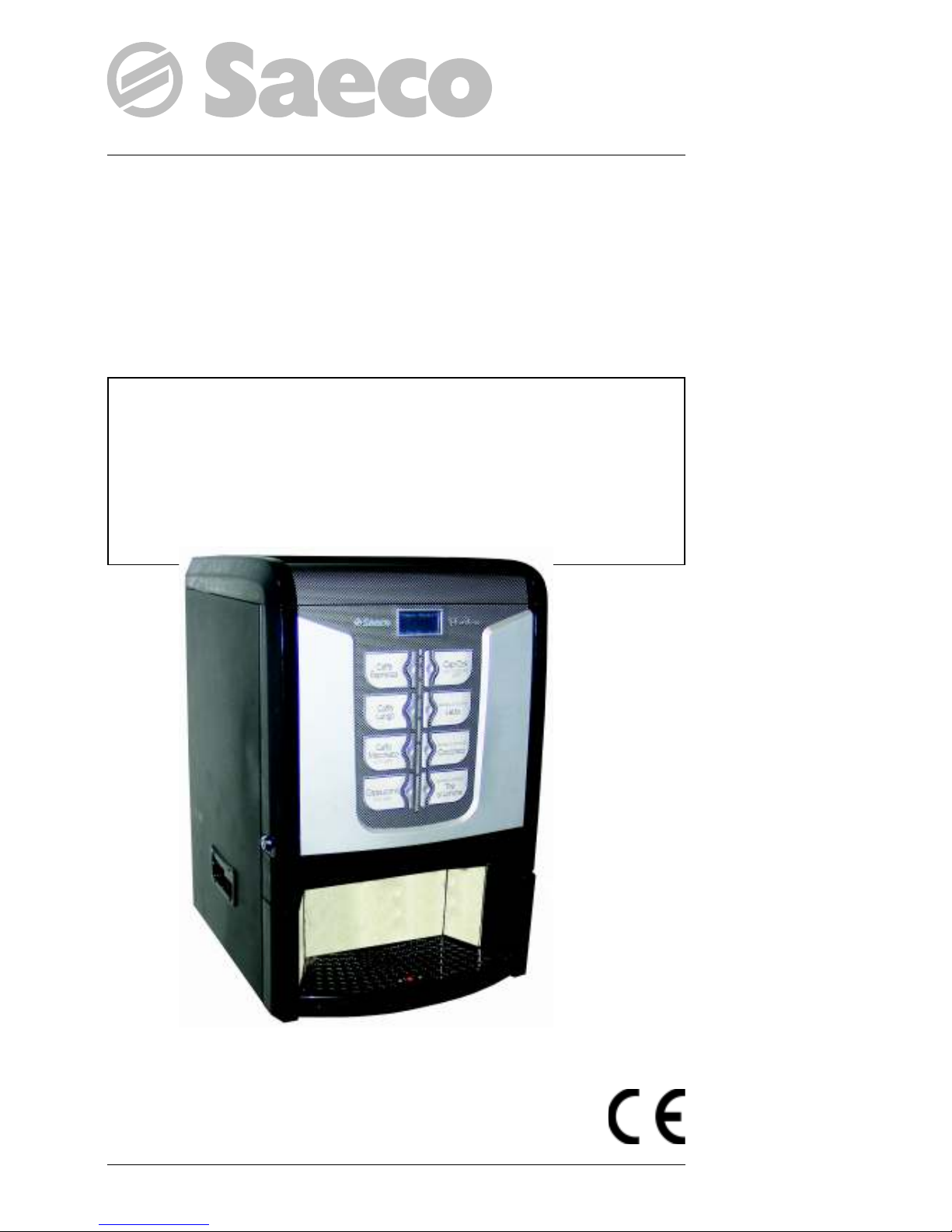
Automatic drink vending machine
Model
PHEDRA
Type: D.A. 5P07
WARNING: This instruction manual is intended exclusively for specialized personnel.
USE AND MAINTENANCE
Page 2

English
2
CONTENTS
CONTENTS ............................................. 2
MAIN PARTS - ESPRESSO VERSION .......... 3
MAIN PARTS - INSTANT VERSION ............ 5
MAIN PARTS - T.T.T. VERSION .................. 7
MAIN PARTS - CAPPUCCINO VERSION .... 9
1 - INTRODUCTION TO THE MANUAL ... 11
1.1 Introduction ...................................................11
1.2 Symbols used ................................................11
2 -
INFORMATION ON THE VENDING MACHINE
... 11
2.1 Information for the Maintenance Technician ..... 11
2.2 Description and intended use..........................12
2.3 Vending Machine Identification ......................12
2.4. Technical specifications .................................13
3 SAFETY ............................................ 13
3.1 Introduction ...................................................13
3.2 General safety regulations .............................. 13
3.3 Operators’ requirements ................................14
3.4 Safety devices ...............................................14
3.5 Residual risks ................................................15
4 - HANDLING AND STORAGE ............. 15
4.1 Unloading and handling ................................15
4.2 Storage ........................................................15
5 - INSTALLATION ............................... 15
5.1 Important ...................................................... 15
5.2 Unpacking and positioning ............................16
5.3 Label application ........................................... 16
5.4 Fitting the payment systems ............................17
5.5 Connection to water mains .............................18
5.6 Connection to the electric network ...................18
5.7 Coffee Grounds Discharge Setting ..................19
5.8 Liquid Drain Setting ....................................... 19
5.9 Drip Tray Locking .......................................... 20
5.10 Front Door Intermediate Locking .....................20
6 - CONTROLS DESCRIPTION ............... 21
6.1 Display .........................................................21
6.2 Keypad ......................................................... 21
6.3 Key description in standard operation mode ....21
6.4 CPU card keys ............................................... 21
7 - SUPPLY AND STARTING UP ............ 22
7.1 Container supply (Espresso) ............................ 22
7.2 Container supply (Instant) ...............................22
7.3 Container supply (T.T.T.) ................................23
7.4 Container supply
(Cappuccino) ......................... 23
7.4.1 Coffee bean supply ............................................ 24
7.4.2 Instant product supply .......................................... 24
7.5 Coffee grinding calibration ............................25
7.6 Dose calibration ............................................25
7.7 First start-up of the vending machine ............... 26
7.8 Filling the boiler manually .............................. 26
7.9 Use of the vending machine ...........................26
8 - PROGRAMMING AND MAINTENANCE
MENU ........................................... 27
8.1 Key description of programming and
maintenance phases ......................................27
8.2 Programming menu .......................................27
8.2.1 Entering the programming menu ............................27
8.2.2 Structure of the programming menu ........................28
8.2.3 Description of messages in the programming menu ... 29
8.3 Maintenance menu ........................................41
8.3.1 Entering the maintenance menu ............................. 41
8.3.2 Structure of the maintenance menu ......................... 41
8.3.3 Description of messages in the maintenance menu ....41
8.4
Machine Ready/Free Button ................................. 43
8.5 Reset ............................................................43
9 - OPERATION AND USE .................... 44
9.1 Beverage selection ........................................ 44
9.2 Cappuccino with cold milk function
(only for Cappuccino version) ......................... 44
10 - CLEANING AND MAINTENANCE ..... 44
10.1 General notes for correct operation ................. 45
10.2 Cleaning and scheduled maintenance .............45
10.2.1 Maintenance schedule ........................................45
10.2.2 Cleaning the Drip Tray and the Coffee Grounds
Drawer .............................................................45
10.2.3
Cleaning the tray and drawer - Version with extension
...45
10.2.4 Cleaning of the coffee brew group ........................ 46
10.2.5 Cleaning the dispensing arm ................................ 46
10.2.6
Cleaning the instant product dispenser and the mixer
... 47
10.2.7 Cleaning the containers ....................................... 48
10.2.8 Cleaning the coffee grinder .................................. 48
10.2.9
Semi-automatic cleaning of the Cappuccinatore
(only for Cappuccino version) ................................49
10.2.10
Manual cleaning of the Cappuccinatore
(only for Cappuccino version) ...............................50
10.3 Software Update ...........................................51
11 - DISPLAY MESSAGES ....................... 52
11.1 Messages during operation ............................52
11.2 Error messages ..............................................52
12 - STORAGE - DISPOSAL .................... 54
12.1 Change of location ........................................54
12.2 Inactivity and storage periods .........................54
13 - INSTRUCTIONS FOR END-OF-LIFE DI-
SPOSAL TREATMENT ...................... 54
Page 3

English
3
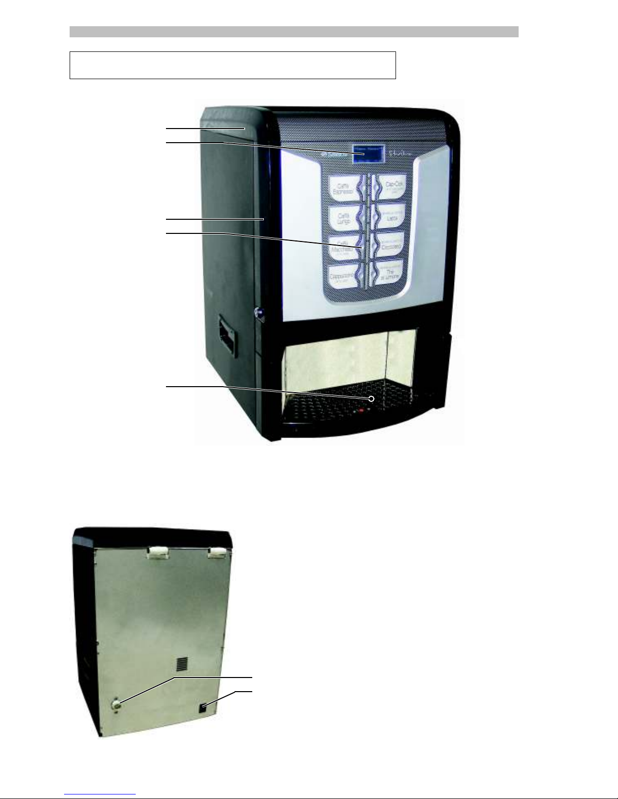
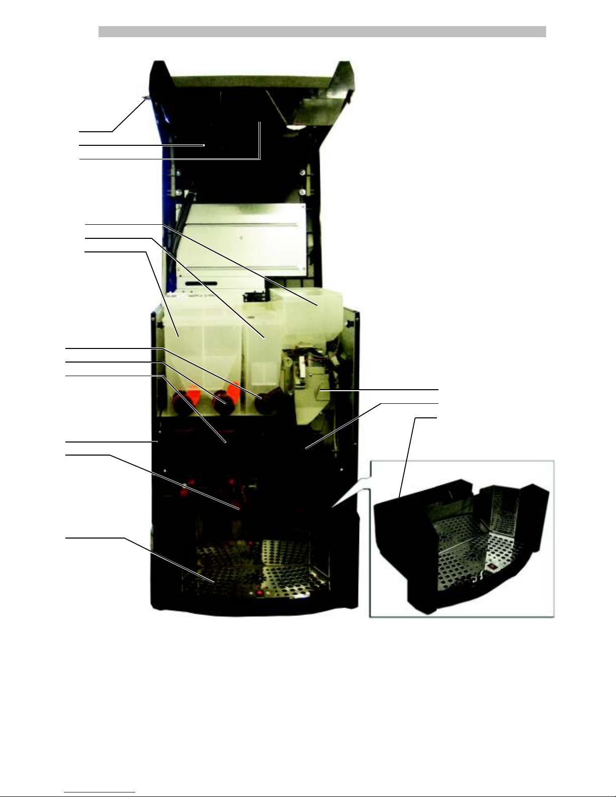
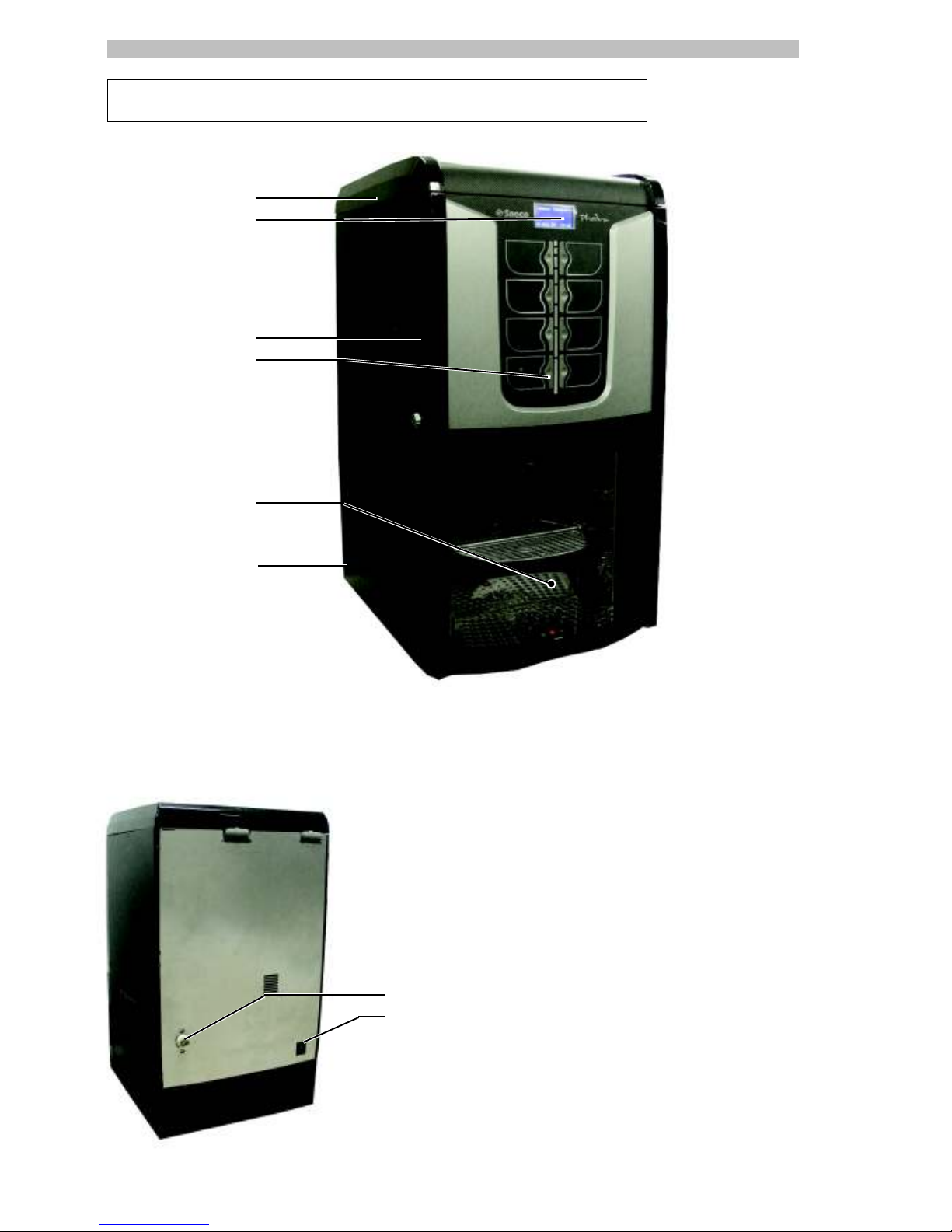
MAIN PARTS - ESPRESSO VERSION
1
2
3
4
5
6
7
Fig. 2
1 Top door
2 Display
3 Front door
4 Buttons
5 Dispensing outlet (beverage dispensing)
6 Coupling for connection to water network
7 Power cord outlet
Fig. 1
Page 4
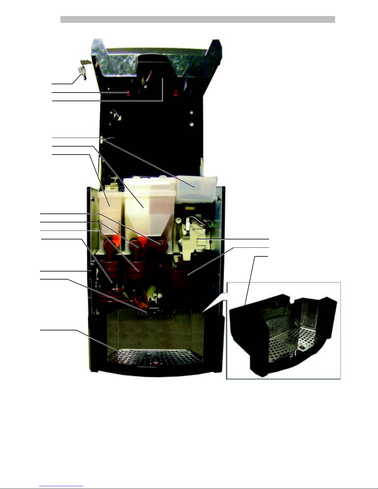
English
4
8 Door lock
9 Front door fastener knob
10 CPU electronic board
11 Coffee bean hopper
12 Container 2/3 (instant products)
13 Container 1 (instant products)
14 Adjustable powder dispensing channel
15 Instant product dispenser
16 Mixer
17 Spiral mixer
18 Safety switch
19 Brewing arm
20 Coffee grounds drawer
21 Grill
22 Coffee grinder
23 Brew group
22
23
8
9
10
11
12
13
14
15
16
17
18
19
21
Fig. 3
20
Page 5

English
5
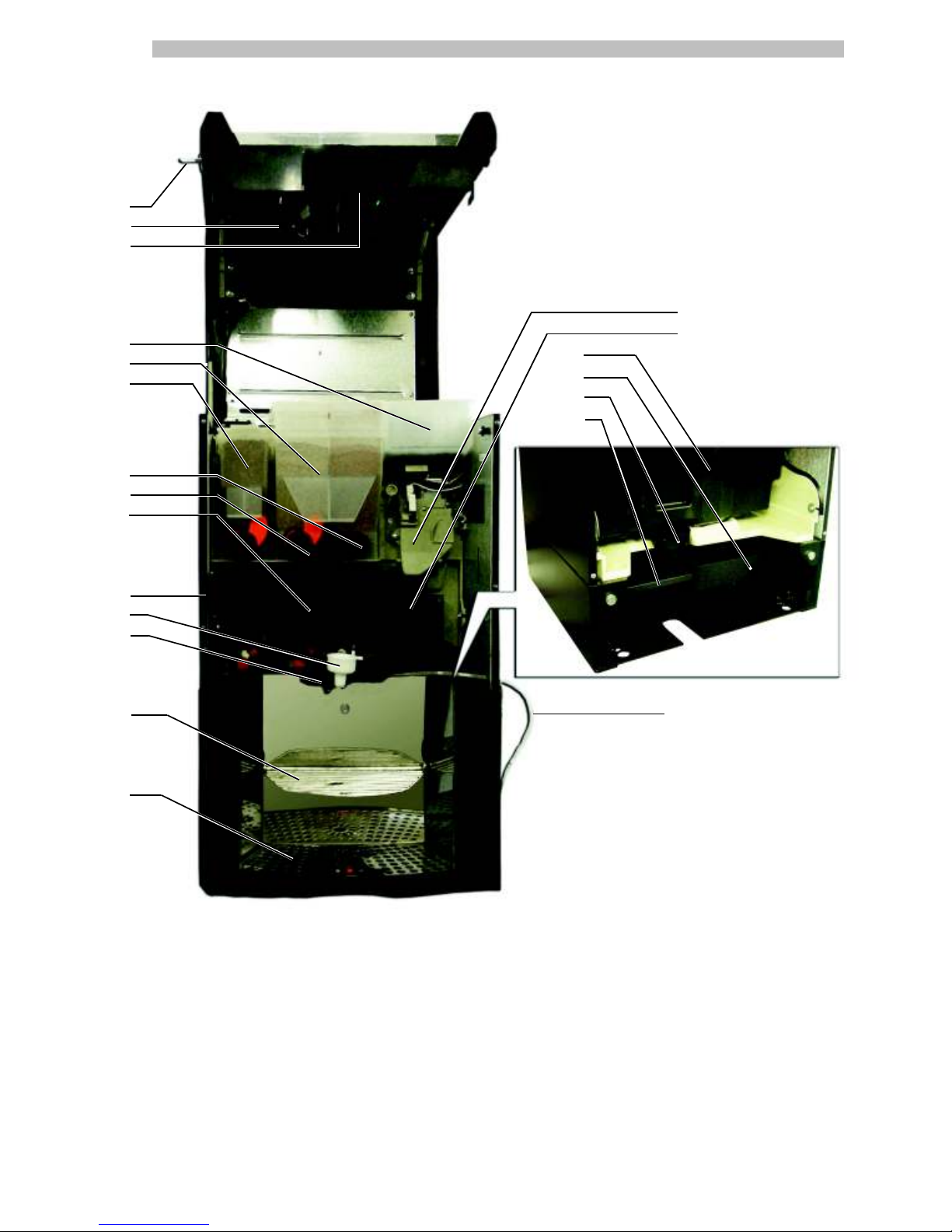
MAIN PARTS - INSTANT VERSION
6
7
Fig. 1
1 Top door
2 Display
3 Front door
4 Buttons
5
Dispensing outlet (beverage dispensing)
6
Coupling for connection to water network
7 Power cord outlet
24 Extension (option)
1
2
3
4
5
Fig. 2
24
Page 6
English
6
8 Door lock
9 Front door fastener knob
10 CPU electronic board
12 Container 2/3 (instant products)
13 Container 1 (instant products)
14 Adjustable powder dispensing channel
15 Instant product dispenser
16 Mixer
18 Safety switch
19 Brewing arm
20 Coffee grounds drawer
21 Grill
25 Container 5 (instant products)
26 Container 4 (instant products)
27 Grill for extension (option)
28 Powder diverter for small-type containers
29 Coffee grounds drawer (option)
30 Drip conveyor (option)
31 Drip tray (option)
28
8
9
10
25
26
12
13
14
15
16
18
19
21
27
20
29
30
31
Fig. 3
Page 7
English
7
MAIN PARTS - T.T.T. VERSION
6
7
Fig. 1
Fig. 2
1 Top door
2 Display
3 Front door
4 Buttons
5
Dispensing outlet (beverage dispensing)
6
Coupling for connection to water network
7 Power cord outlet
1
2
3
4
5
Page 8
English
8
8 Door lock
9 Front door fastener knob
10 CPU electronic board
11 Coffee bean hopper
12 Container 1/2 (instant products)
14 Adjustable powder dispensing channel
15 Instant product dispenser
16 Mixer
18 Safety switch
19 Brewing arm
20 Coffee grounds drawer
21 Grill
22 Coffee grinder
32 Container 3 (“fresh brew” pre-ground coffee)
33 T.T.T. Brew group
22
33
8
9
10
11
32
12
14
15
16
18
19
21
Fig. 3
20
Page 9
English
9
MAIN PARTS - CAPPUCCINO VERSION
6
7
Fig. 1
1 Top door
2 Display
3 Front door
4 Buttons
5
Dispensing outlet (beverage dispensing)
6
Coupling for connection to water network
7 Power cord outlet
24 Extension (option)
1
2
3
4
5
Fig. 2
24
Page 10
English
10
8 Door lock
9 Front door fastener knob
10 CPU electronic board
11 Coffee bean hopper
12 Container 2/3 (instant products)
13 Container 1 (instant products)
14 Adjustable powder dispensing channel
15 Instant product dispenser
16 Mixer
18 Safety switch
19 Brewing arm
20 Coffee grounds drawer
21 Grill
22 Coffee grinder
23 Brew group
27
Grill for extension (option)
29 Coffee grounds drawer (option)
30 Drip conveyor (option)
31 Drip tray (option)
34 Cappuccinatore
35 Hose for Cappuccinatore
8
9
10
11
12
13
14
15
16
18
34
19
21
27
20
29
30
31
Fig. 3
22
23
35
Page 11
English
11
User
Indicates the user of the vending machine. This person is
not authorized to carry out any cleaning or maintenance
operation.
Supply operator
Indicates operations to be carried out only by personnel in
charge of supplying and cleaning the vending machine.
Maintenance operations requiring a Maintenance Technician
are not to be performed by the supply operator.
Maintenance Technician
Indicates operations to be carried out by qualified personnel
in charge of maintenance.
The Maintenance Technician is the only person authorized
to keep the MICROSWITCH ENABLING KEY, by which the
security systems can be disabled.
2 - INFORMATION ON THE
VENDING MACHINE
2.1 Information for the
Maintenance Technician
The vending machine must be installed in a well-lit, dry and
not dusty area, protected from exposure.
To guarantee the correct operation and reliability over time,
the following is recommended:
- ambient temperature: from +1°C to +32°C;
- maximum humidity: 90% (not condensed).
For special installations not covered in this publication,
please contact the dealer or the local importer. If this is not
possible, please contact the Manufacturer directly.
AUTHORIZED CUSTOMER SERVICE CENTRES are available
for information and explanations about the vending machine,
and to provide technical assistance or spare parts.
The Maintenance Technician must carefully read and respect
the safety warnings contained in this manual so that every
intervention concerning installation, starting up, use and
maintenance will be safely carried out.
It is the Maintenance Technician’s absolute responsibility to
give the keys to access the inside of the vending machine
to another operator (Supply Operator), provided that the
Maintenance Technician bears full responsibility for all work
carried out.
This manual is an integral part of the machine and must be
always read carefully before performing any operation.
1 - INTRODUCTION TO THE
MANUAL
1.1 Introduction
Important
This publication is an integral part of the vending machine and
must be read carefully to ensure the machine is used correctly
and in compliance with essential safety requirements.
This manual contains the technical information required for
the correct use, installation, cleaning, and maintenance of
the vending machine model PHEDRA. Always refer to this
publication before carrying out any operation.
Manufacturer: SAECO Vending S.p.A.
Località Casona, 1066 - 40041 Gaggio Montano
Bologna, Italy
This publication should be kept carefully, together with the
vending machine throughout its operational life, even in case
of changes of ownership.
Should this manual be lost or worn out, a copy can be
requested from the Manufacturer or an Authorized Customer
Service Centre by indicating all data on the identification
plate on the back of the vending machine.
1.2 Symbols used
This publication contains various warnings which indicate
different degrees of danger or skills required.
The symbol is integrated with a message suggesting use
procedures or actions and providing useful information for
the correct operation of the machine.
Warning
Indicates dangerous situations for the users, supply operators
and maintenance technicians dealing either with the vending
machine or the product to be dispensed.
Important
Indicates the operations for keeping the vending machine in
good working order.
Recommended solutions
Indicates alternative procedures that make the programming
and/or maintenance operations quicker.
Page 12
English
12
2.2 Description and intended
use
The vending machine is intended for automatic distribution of
coffee and hot beverages (decaffeinated coffee, cappuccino,
chocolate, etc.) and is programmable for every single type of
dispensing dosage. The instant products must be consumed
immediately, and cannot be preserved for a long time.
Any other use is to be considered improper and therefore
dangerous.
Do not place any product inside the distributor which may
be dangerous as a result of unsuitable temperatures.
With reference to the definition of “professional appliance” given by the
standard EN60335-2-75 for vending machines, this appliance can not be
classed as professional.
Important
Improper use of the vending machine invalidates all warranties.
The Manufacturer declines any liability for damage to property
or injury to persons.
Improper use also includes:
- any use of the vending machine other than the intended use
and/or according to procedures which are not described
in this publication;
- any intervention on the vending machine which differs from
the instructions given in this publication;
- any alteration of components and/or safety devices
without prior consent of the Manufacturer or carried out
by personnel not authorized for such operations;
- any location of the appliance which is not recommended
in this manual.
Fig. 4
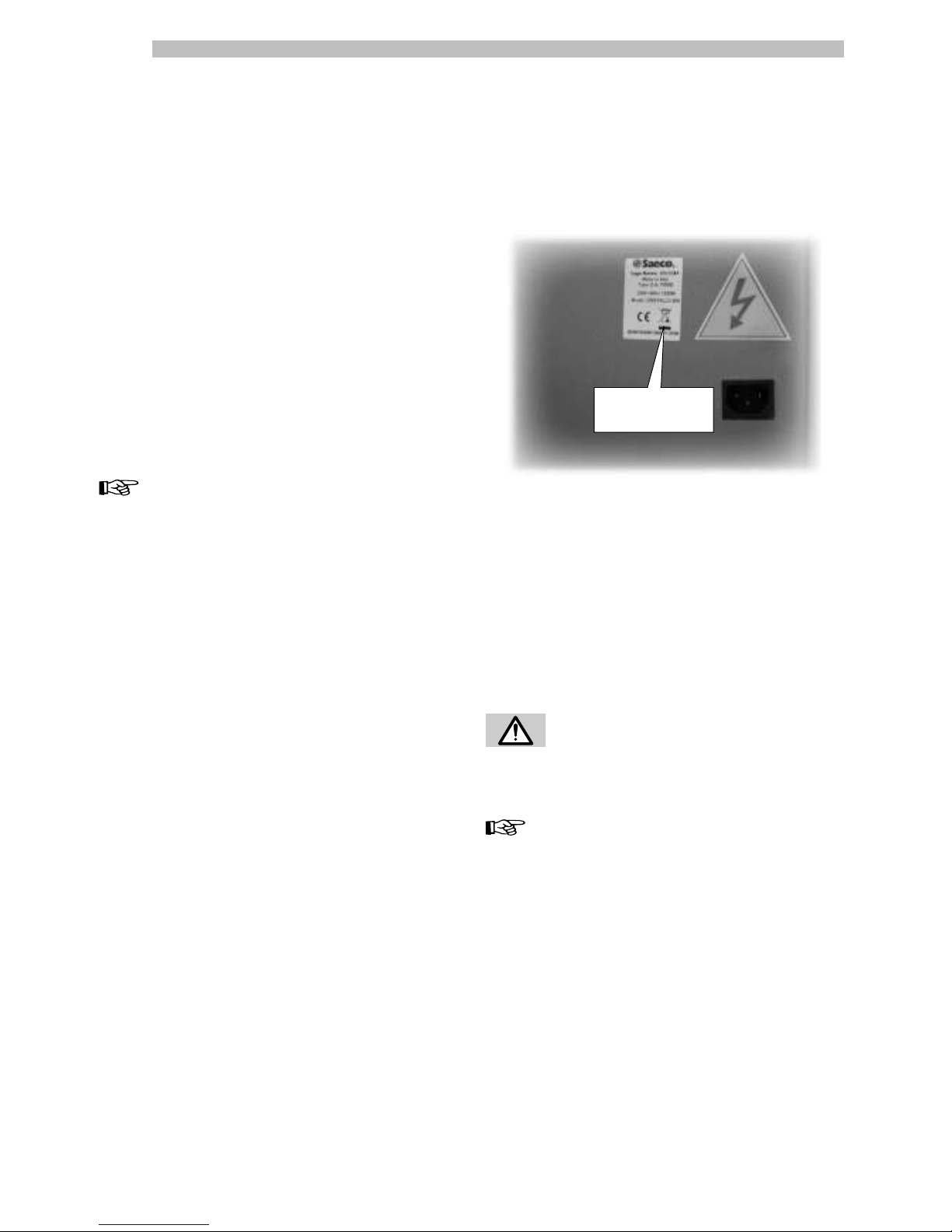
Data plate
2.3 Vending Machine
Identification
The vending machine is identified by the name, model and
serial number which can be found on the relevant data
plate (Fig. 4).
The following data can be found on the plate:
- name of Manufacturer;
- marks of compliance;
- model;
- serial number;
- year and month of manufacture;
- supply voltage (V);
- supply frequency (Hz);
- electrical power consumption (W).
Warning
It is strictly forbidden to tamper with or modify the data
plate.
Important
When contacting the AUTHORIZED CUSTOMER SERVICE
CENTRES always refer to this plate and its relevant data.
Page 13
English
13
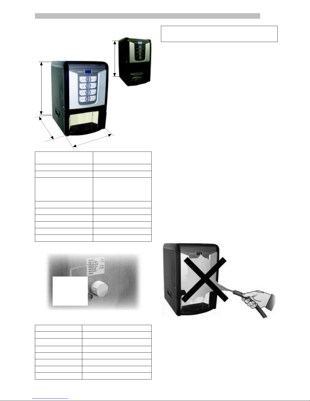
Fig. 6
2.4. Technical specifications
Data plate
showing minimum
and maximum
water supply
pressure
Container capacity
Coffee beans
: 1,00 kg
Chocolate
: 1,75 kg
Milk
: 0,65 kg
Lemon tea
: 1,50 kg
Ginseng:
double: 1,85 kg, standard: 1,15 kg
Ground coffee: 0,62 kg
Freeze-dried coffee:
standard: 0,41 kg, small: 0,23 kg
Barley:
standard: 0,36 kg, small: 0,20 kg
Height:
594 mm standard
714 mm with extension
Width: 394 mm
Depth: 430 mm
Weight:
31 kg Espresso
35 kg Instant with extension
31 kg T.T.T.
38 kg Cappuccino with extension
Power consumption: see data plate
Supply voltage: see data plate
Electric voltage frequency: see data plate
Power cord length: 1,600 mm
Water mains connection: 3/4” Gas type
Water mains pressure: see figure 6
3 SAFETY
3.1 Introduction
In compliance with the Low Tension Directive 2006/95/
EC (which replaces the directive 73/23/EEC and following
amendments) and CE Marking Directive 93/68/EEC,
SAECO VENDING has drawn up a technical file of the
PHEDRA vending machine held at its plants. The following
regulations were taken into account during the design
phase:
- EN 55014 - EN 6100-3-2
- EN 61000-3-3 - EN 61000-4-2
- EN 61000-4-3 - EN 61000-4-4
- EN 61000-4-5 - EN 61000-4-11
- EN 60335-2-75 - EN 60335-1
3.2 General safety regulations
It is forbidden to:
- tamper with or disable the safety systems installed on the
vending machine;
- carry out maintenance on the vending machine without
unplugging it first;
- install the vending machine outdoors. It should be placed in
dry areas where the temperature never falls below 1°C;
- use the vending machine for purposes other than those
indicated in the sale contract and in this publication;
- connect the appliance to the mains using multi-sockets or
adapters;
- use water jets to clean the vending machine (Fig. 6).
It is compulsory to:
- check the electrical power line for conformity;
- use original spare parts;
- read the instructions contained in this publication and in
the enclosed documents carefully;
- use personal protection devices during installation, testing
and maintenance operations.
Fig. 7
Fig. 5
594
430
394
714
Standard version
Extension version
Page 14
English
14
Precautions for preventing human errors:
- make the operators aware of safety issues;
- handle the vending machine, either packaged or
unpackaged, in safe conditions;
- have a thorough knowledge of the installation procedures,
its operation and limits;
- dismantle the vending machine in safe conditions, in
accordance with the environmental protection and health
and safety laws in force.
Warning
In case of failure or malfunctioning contact only qualified
CUSTOMER SERVICE personnel.
Important
The Manufacturer declines any liability for any damage
caused to property or injury caused to persons as a result of
failure to observe the safety regulations described here.
Important
This appliance is not intended for use by persons (including
children) with reduced physical, sensory or mental capabilities,
or lack of experience and knowledge, unless they have
been given supervision or instruction concerning use of the
appliance by a person responsible for their safety.
3.3 Operators’ requirements
Three operators with different skills are required in order to
guarantee the safety of the vending machine:
User
Access to the internal part of the vending machine is forbidden
to the user.
Supply operator
The Maintenance Technician assigns the safekeeping of the
access key to the Supply operator who is in charge of product
supply, external cleaning, and starting up / stopping of the
vending machine.
Warning
The Supply Operator is not authorized to carry out operations
which are indicated as being the duties of the Maintenance
Technician in this publication.
Maintenance Technician
The Maintenance Technician is the only person authorized
to intervene and start programming procedures, and perform
adjusting, setting up and maintenance operations on the
vending machine.
Fig. 8
3.4 Safety devices
The vending machine is equipped with:
- A microswitch (Ref. 18, Fig. 8) automatically cuts out the
power supply when the front panel is opened.
The microswitch can be disabled by inserting the key (Ref.
24, Fig. 8).
- A microswitch (Ref. 25, Fig. 8) blocks vending machine
operation when the drip tray and/or coffee grounds
drawer are not correctly positioned. A message indicating
the incorrectly positioned part appears on the display.
Maintenance Technician
In case of programming or setting up operations only the
Maintenance Technician can intervene by inserting the
relevant key into the safety switch (rif. 24, fig. 8) and resetting
the voltage even if the door is open.
Warning
This operation, necessary for starting up the vending machine,
disables the safety system.
It must therefore be carried out by qualified personnel
(Maintenance Technician) aware of the risks resulting from
the presence of live or moving components.
25
18
24
Page 15
English
15
3.5 Residual risks
Warning
Risk of scalding if hands are placed inside the outlet during
brewing.
Do not remove the cup or put your hands inside the
compartment during beverage brewing before the brewing
cycle has finished.
Before removing the cup from the outlet, please wait for the
message “REMOVE CUP” on display.
Important
Before brewing another beverage, check that the previous
one has been taken out and that the cup support is empty.
4 - HANDLING AND
STORAGE
4.1 Unloading and handling
Unloading and handling operations after transportation
must be carried out only by qualified personnel and using
suitable equipment.
Warning
The vending machine must always be kept in the upright
position. Avoid:
- dragging the vending machine;
- overturning or laying the vending machine flat during
transport and handling;
- shaking the vending machine;
- leaving the vending machine exposed to the elements, in
humid areas or close to heat sources.
4.2 Storage
If the vending machine is not installed immediately, it should
be stored in a sheltered area, conforming to the following
instructions:
- the packaged vending machine must be stored in a closed,
dry area at a temperature between 1°C and 40°C;
- do not put other appliances or boxes on the vending
machine;
- it is always good practice to protect the vending machine
from any deposits of dust or other material.
Fig. 9
5 - INSTALLATION
5.1 Important
Warning
The vending machine cannot be installed outdoors; avoid
placing it in areas where the temperature is less than 1°C or
more than 32°C and in particularly dump or dusty areas.
Before unpacking, check that the installation area complies
with the following specifications:
- the power socket must be located in an easily accessible
area, not more than 1.5 meters away;
- the socket voltage must comply with that on the identification
plate;
- the surface or floor must NOT have a gradient of more
than 2°.
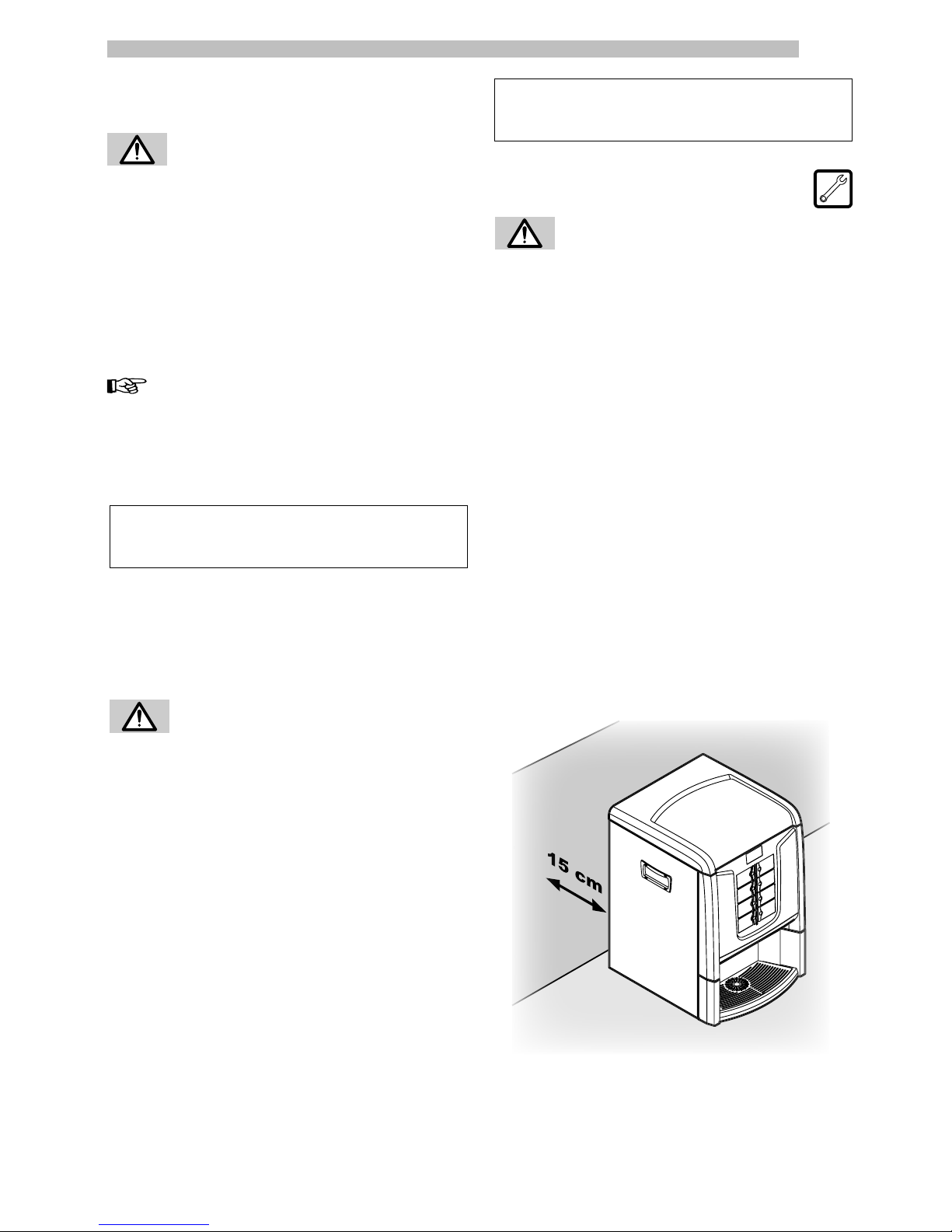
If the vending machine needs to be positioned close to a wall,
it is necessary to leave a space of at least 15 cm between
the back and the wall in order to keep the air outlet grille
free (Fig. 9).
Page 16
English
16
Fig. 10
- Instruction booklet
- Power cord
- Product labels and prices
The vending machine is protected by an expanded
polyethylene foam sheet and a plastic bag inside a box
(Fig. 11).
5.2 Unpacking and
positioning
On receipt of the vending machine make sure that it has
not been damaged during transportation and that package
has not been tampered with or that internal parts have not
been removed.
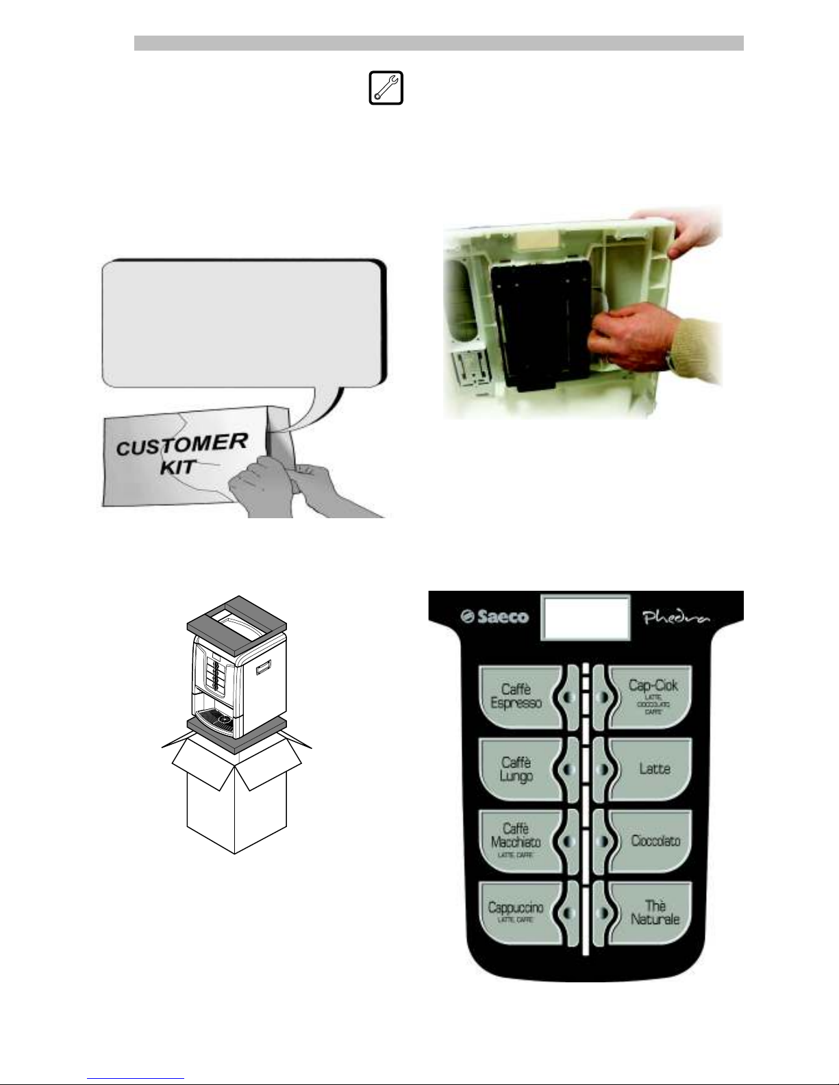
An envelope, called “CUSTOMER KIT” is supplied with the
vending machine; it contains the objects shown in Fig. 10.
Fig. 11
If damage of any kind is found, the courier must be informed
and notice must be given to the importer or the seller
immediately. If these are not in the purchaser’s country,
please contact the manufacturing company directly.
The accessory bag contains:
- 1 key for the brew group;
5.3 Label application
Product labels
Open the vending machine. Insert the product labels (Fig.
12).
Check the exact position of the labels against the selection
key (Fig. 13a,13b, 13c, 13d).
Fig. 12
Fig. 13a
Espresso version
Page 17
English
17
5.4 Fitting the payment
systems
Important
The vending machine is not supplied with any payment
system, which must be installed by the person in charge of
its fitting.
The vending machine is designed for the installation of
various payment systems, such as:
- Parallel coin validator, 24 V DC
- Cashless reader (EXECUTIVE, PRICE HOLDING, MDB, and
BDV systems)
Coin
validator
Cashless
reader
Fig. 13b
Fig. 13c
Instant version
T.T.T. version
Fig. 13d
Cappuccino version
Fig. 14
Page 18

English
18
Fig. 15
5.5 Connection to water
mains
Important
The pressure reducer is calibrated during assembly. Should
problems occur with the calibration of the pressure reducer,
the outlet pressure value must absolutely be reset to 0.8 – 1
bar max. Different or approximate calibration may cause
product quality and quantity variations when brewed.
Important
It is recommended to use a descaling device for the water
network supplying the vending machine, especially for water
with a high calcium and magnesium content (hard water).
Connect the vending machine to a drinking water supply
pipe with a pressure ranging between 1.5 and 8 bars (see
data plate).
Important
Before connecting the appliance to water network, please
read and follow the applicable regulations in force in your
country.
Remove the cap from the coupling placed on the vending
machine back panel (Fig. 15). Connect the water supply
pipe to the 3/4” Gas coupling of the vending machine
(Fig. 15).
5.6 Connection to the
electric network
Warning
The Maintenance Technician, who is responsible for the
installation of the vending machine, must ensure that:
- the electr ic system c ompli es with current safety
regulations;
- the supply voltage corresponds to that indicated on the
data plate.
If in doubt, do not proceed with the installation and ask
qualified and authorized personnel to check the system
accurately.
The vending machine is equipped with a power cord which
must be plugged into the appropriate socket on the vending
machine back panel (Fig. 16).
Important
After the chosen payment system has been installed,
the corresponding parameters can be set through the
programming menu (see 8.2).
Warning
The Manufacturer declines any liability for any damage to the
vending machine, to property and/or injury to persons, caused
by the installation of the payment system. The responsibility
falls to the person who carried out the installation.
Page 19

English
19
5.7 Coffee Grounds Discharge
Setting
The appliance is setup for direct discharge of the coffee
grounds into the bag in the dedicated cabinet or into another
container located below the appliance (ex. bar counter).
For this setting, the plate (Ref. A, Fig. 18) and coffee grounds
drawer (Ref. A, Fig. 19) must be cut along the indicated
marks.
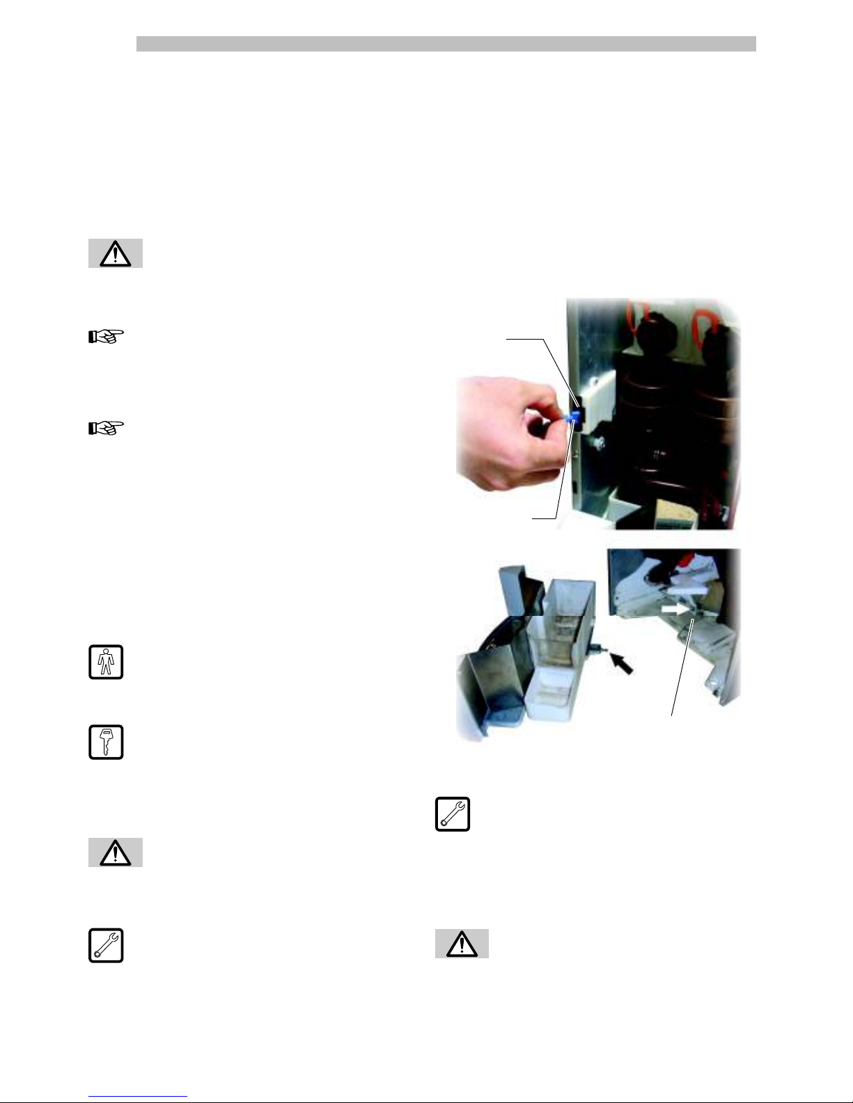
Remove the tab the coffee grounds drawer hooks to (Ref. B,
Fig. 19) using a cutter or a jigsaw.
Fig. 18
Fig. 19
Fig. 20
A
A
B
A
Important
The appliance has an alarm signal to indicate when to empty
the coffee grounds in the standard version. For this setting it
is necessary to exclude this counter using the menu.
5.8 Liquid Drain Setting
The appliance is setup for direct drainage of the drip tray into
container in the dedicated cabinet or into another container
located below the appliance.
To use this setting, cut (or drill a hole in) the panel in the
indicated area (Ref. A, Fig. 20).
Do not use adapters or multi-sockets (Fig. 17).
Fig. 17
Fig. 16
Page 20

English
20
5.9 Drip Tray Locking
Important
This option can be used to guarantee the appliance additional
safety.
It is possible to block the removal of the drip tray without
opening the door.
To use this option, remove the two locking pins integrated
on the drip tray (Ref. A, Fig. 21).
Divide them and, after trimming them with a cutter, glue them
on the two studs (Ref. A, Fig. 22) located on the lower front
part of the drip tray (thus lengthening the centring pieces).
In this manner, it will no longer be possible to remove the
drip tray without first opening the door.
Fig. 21
Fig. 22
A
A
5.10 Front Door Intermediate
Locking
In order to perform an unscheduled maintenance lock the
front door as shown in Fig. 23.
Fig. 23
Fig. 24
This is possible after opening the vending machine, by
turning the key clockwise and fitting the slots (Ref. A, Fig.
24) on the pins (Ref. B, Fig. 24).
B
A
Page 21

English
21
Fig. 26
6.4 CPU card keys
The CPU electronic card has 4 keys enabling the Maintenance
Technician to carry out programming or maintenance
operations (Fig. 26).
6 - CONTROLS
DESCRIPTION
6.1 Display
The display (2 - Fig. 1) shows the messages during standard
operation, programming and maintenance modes.
6.2 Keypad
Important
Each key function changes according to the vending machine
mode (ordinary dispensing or programming mode).
Each key has a double function that varies according
to the vending machine status (standard operation or
programming).
6.3 Key description in
standard operation mode
Keys (1 to 8 - Fig. 25)
By pressing these keys, the programmed beverages are
dispensed.
1
2
3
4
5
6
7
8
Fig. 25
Page 22

English
22
7 - SUPPLY AND STARTING
UP
7.1 Container supply
(Espresso)
Important
The containers delivered are designed to dispense the
following products (Fig. 27a):
Instant product 1 = Tea
Instant product 2 = Milk
Instant product 3 = Chocolate
Fig. 27a
Instant
product 1
Coffee bean
Instant
product 2
Instant
product 3
7.2 Container supply
(Instant)
Important
The containers delivered are designed to dispense the
following products (Fig. 27b):
Instant product 1 = Tea
Instant product 2 = Milk
Instant product 3 = Chocolate
Instant product 4 = Barley
Instant product 5 = Freeze-dried coffee
Fig. 27b
Instant
product 1
Instant
product 2
Instant
product 3
Instant
product 4
Instant
product 5
Page 23

English
23
Fig. 27d
7.3 Container supply
(T.T.T.)
Important
The containers delivered are designed to dispense the
following products (Fig. 27c):
Instant product 1 = Tea
Instant product 2 = Milk
Instant product 3 = Ground coffee
Fig. 27c
Instant
product 1
Coffee bean
Instant
product 2
Instant
product 3
7.4 Container supply
(Cappuccino)
Important
The containers delivered are designed to dispense the
following products (Fig. 27d):
Instant product 1 = Freeze-dried coffee
Instant product 2 = Ginseng
Instant product 3 = Chocolate
Instant
product 1
Instant
product 2
Instant
product 3
Coffee bean
Fresh milk
container
Page 24

English
24
7.4.2 Instant product supply
Open the cover of the container to be supplied (Fig. 30).
Fig. 30
Pour the instant product into the container (Fig. 31).
Fig. 31
7.4.1 Coffee bean supply
Remove the container cover (Fig. 28).
Fig. 28
Fig. 29
Replace the cover on the container.
Important
If the message “COFFEE NOT AVAILABLE” is displayed after
the supply, the following operations should be carried out:
- press the “P2” key (Fig. 26) to enter the maintenance
menu;
- press the key “e” twice (Fig. 36) to eliminate the error (see
sect. 8.3.3 Description of messages in the maintenance
menu).
Put coffee beans into the container (Fig. 29).
Close the container cover.
Page 25

English
25
7.6 Dose calibration
The vending machine is delivered with standard
calibration values set by the manufacturer. The quantity of
coffee powder is set to 7.0 gr.
Dose calibration can be performed by means of two
calibration levels:
- remove the cover (Fig. 33);
Fig. 33
- move the adjusting lever into the rack and select the slot
corresponding to the dose required (Fig. 35).
- release the adjusting lever from the rack and place
- the dragging tooth of the inner panel on one of the 4
positions available, which indicate the basic quantity area
(6 gr. – 7 gr. – 8 gr. – 9 gr.) (Fig. 34);
Fig. 34
Fig. 35
Fig. 32
7.5 Coffee grinding
calibration
Turn the ring (Fig. 32) until the required results are obtained.
After any calibration three selections are necessary before
the new setting becomes effective.
Page 26

English
26
7.8 Filling the boiler
manually
Manual filling of the boiler is required during the first startup of the vending machine.
After switching on the vending machine, it is possible to fill
the boiler by means of the following procedure:
- press the “P2‰ key (Fig. 26) to enter the maintenance
menu;
- press the “e” key (Fig. 36) followed by the “UP” key
(Fig. 36) to access the RINSING entry;
- press the “e” key (Fig. 36) to carry out the automatic
complete rinsing cycle.
- repeat the washing operation until water comes out of
the beverage dispensing nozzles.
Important
The rinsing operation must be repeated until water flows out
of the brewing nozzles regularly.
7.9 Use of the vending
machine
The beverage selection procedures are shown in section 9.
7.7 First start-up of the
vending machine
Supply the vending machine (following the instructions given
previously) and plug it into the power supply (see 5.6).
At this point, the message “PHEDRA” appears on the display
and the self-configuration is turned on.
Any faults detected during the self-configuration cycle are
stored so that the vending machine can display them at the
end of the self diagnostic phase.
Adjust grinding as instructed in 7.2; the boiler must be
necessarily filled.
Page 27

English
27
8.2 Programming menu
The structure of the programming menu is shown in 8.2.2.
8.2.3 describes all the entries in the programming menu.
8.2.1 Entering the programming
menu
Open the door, disable the safety device (see 3.4) and press
the “P1” key (Fig. 26) to enter the programming menu.
If no password has been assigned, the programming menu
is entered directly.
Important
If a password was assigned to the vending machine to
enable the programming menu, the message “PASSWORD
000000” will appear on the display with a flashing cursor
on the first digit.
Now the password should be entered using the UP and
DOWN keys. Confirm the digit entered by pressing the
ENTER key.
Proceed as follows to exit the programming menu and return
to standard operation of the vending machine:
- Press the ESC button repeatedly until “EXIT ?” appears.
Select YES and press ENTER.
- remove the key from the safety switch in order to turn off
the vending machine;
- close the door and wait for the self-configuration process
to end.
8 - PROGRAMMING AND
MAINTENANCE MENU
Important
This section illustrates how to set up or modify the vending
machine programming and maintenance settings.
It is therefore necessary to read it carefully, and intervene only
when the correct sequence of operations to be performed is
fully understood.
8.1 Key description of
programming and
maintenance phases
To scroll through the vending machine menu, the keys
described below are used.
„e‰ Key: ENTER (Fig. 36)
By pressing this key it is possible to enter the following
programming or maintenance level. It is also possible
to modify or confirm the values set in the entries of the
programming or maintenance menus.
„c‰ Key: CANCEL (Fig. 36)
By pressing this key it is possible to go back to the previous
level of the programming or maintenance menu. It is also
possible to avoid storing the previously modified values.
„V‰ Key: DOWN (Fig. 36)
Pressing this key it is possible to access the previous entry
inside the same level.
If used after a setting modification request, the value of this
setting decreases.
„^„ Key: UP (Fig. 36)
By pressing this key it is possible to access the next entry
inside the same level.
If used after requesting the change of a setting, the value of
this setting increases.
e
c
Fig. 36
^
^
Page 28

English
28
8.2.2 Structure of the programming menu
1. System manag.
1.1. VMC code
1.2. Stop
1.2.1. Stop coffee
1.2.2. Stop Preground
1.2.3. Stop beverages
1.2.4. CofGrounds contr
1.2.5. Stop CofGrounds
1.2.6. Reset
1.3. Water filter
1.3.1.
Last filter change
1.3.2. Remaining qty
1.3.3. Filter limit
1.3.4. Filter reset
1.3.5. Filter enabled
1.4. Boiler 1 Temp.
1.4.1. Min temperature
1.4.2. Max temperature
1.5. Boiler 2 Temp.
1.6. EnergySave
1.6.1. Stand-By Timeout
1.6.2. Eco Timeout
1.6.3. Delta Temp. ECO
1.7. PreHeat
1.7.1. Coffee preheat.
1.7.2. InstProd preheat
1.7.3. Capp. PreHeat
1.8. Steam Cleaning
1.8.1. Steam clean time
1.8.2. EnableSteamWash
1.9. Rinse cycle
1.10. Pre-grinding
1.11. Program messages
1.11.1. Stand-by
1.11.2. Preselection
1.11.3. Brewing
1.11.4. Out of service
1.12. Contrast
1.13. Pulse counter
1.14. Clock
1.14.1. Time
1.14.2. Date
1.15. Multiple bever.
1.15.1. Multiple bever.
1.15.2. Enable MultBev
1.16. Enable reset
1.17. Free prod button
1.18. Presel. button
1.19. Language
1.20. Change password
1.20.1. Prog. password
1.20.2. Service password
1.21. On/Off time
1.21.1. On 1
1.21.2. Off 1
1.21.3. On 2
1.21.4. Off 2
1.22. EVA-DTS
1.22.1. EA1..2 (Events)
1.22.2. EA3..5 (Readout)
1.22.3. LA1-Prices Lists
1.22.4. PA1..4 Products
1.22.5. VA1..3 Sales
1.22.6. BA1-CA15-Cash
1.22.7. DA1..7-CashLess
1.23. Audit Msg.Enable
1.24. Ev Water Assign.
1.25. Complete Menus
1.26. VM Model
1.27. Factory Default
1.28. System Info
2. Payment system
2.1. Protocol
2.2. Parallel coiner
2.2.1. Enable
2.2.2. Coin values
2.3. Banknote reader
2.3.1. Enable
2.3.2. Inhibition level
2.3.3. Banknote values
2.4. MDB settings
2.4.1. Recharge enabled
2.4.2. Max CardRecharge
2.4.3. Max card charge
2.4.4. Coins enabling
2.4.5. Alt. payout
2.4.6. Max change
2.4.7. Exact change
2.4.8. Min tube level
2.4.9. Tube filling
2.4.10.
Tube emptying
2.4.11.
Commit to vend
2.4.12.
Banknote enabl.
2.4.13.
Banknote escrow
2.4.14.
Slave address
2.5. Max credit
2.6. Multivend
2.7. Overpay time
2.8. Fixed zeros
2.9. Decimal digits
3. Product setup
3.1. Prod. before
3.1.1. Instant Product
3.1.2. Instant Product
3.1.3. Instant Product
3.1.4. Instant Product
3.1.5. Instant Product
3.2.
Beverage enabled
3.3.
Beverage brewing
4.
Sales management
4.1. Price table
4.1.1. Price (1-100)
4.2. Beverage prices
4.2.1. Normal
4.2.2. Diff 1
4.2.3. Diff 2
4.2.4. Card
4.3. Free
4.4. Free on
4.5. Free off
4.6.
Diff Prices 1-On
4.7.
DiffPrices 1-Off
4.8.
Diff Prices 2-On
4.9.
DiffPrices 2-Off
Page 29

English
29
8.2.3 Description of messages in the
programming menu
SYSTEM MANAGEMENT
The SYSTEM MANAGEMENT
items are:
VM Code
Enables an identification code
to be assigned to the vending
machine.
Stops
Enables setting of the maximum
amount of beverage or coffee.
Once the maximum amount is
reached, the vending machine stops dispensing the relevant
beverages.
STOP COFFEE
Enables setting of the maximum
number of coffee cups to be
dispensed before the stop.
BLOCCO PREGOUND
It allows setting the maximum
number of beverages with pre-
ground coffee to be brewed
before stopping the pre-ground products.
STOP BEVERAGES
Enables setting of the maximum
number of beverages to be
dispensed before the stop.
COFGROUNDS CONTR
Enables or disables control
of the number of grounds
discharged into the coffee
grounds drawer.
When set to “YES” the machine will allow a certain number
of cups of coffee to be brewed before requiring the drawer
to be emptied (see “STOP COFGROUNDS”).
When set to “NO” the machine will not control the number
of grounds discharged into the drawer.
STOP GROUNDS
It allows you to set the maximum
number of coffee cups to be
brewed, corresponding to
maximum dump box capacity. Once reached the set
quantity, coffee-based beverages dispensing is stopped.
Five cups of coffee before the lock is engaged, a
blinking message appears on the display, “EMPTY
COFGROUNDS”.
Important
This lock can be reset by removing the coffee grounds drawer
for at least 10 seconds.
Recommended solutions
It is advisable to set a max. of 30 coffees when using the
dump box supplied with the machine
Important
Do not set any stop value if you are using the machine together
with the supporting cabinet, which is equipped with its own
dump box which is not controlled electronically
RESET
Enables resetting of all partial
counters relative to product
quantity stop functions.
Water Filter
(Only if Complete Menus are
enabled) Allows the use of the
water filter to be checked.
LAST FILTER CHANGE
Date of the last filter reset.
REMAINING QTY
Number of litres of water
that can still be dispensed
before the filter needs to be
regenerated. When this value is less than 1, a Warning
(W83) is recorded in the Error LOG.
FILTER LIMIT
Number of litres of water that
can still be dispensed from the
filter.
FILTER RESET
Select YES to indicate a new
filter has been installed. This
operation returns “Remaining
Qty” to the same value as “Filter Limit” and the date in the
“Last Filter Change” is changed to today’s date.
FILTER ENABLED
Enables management of the
“Remaining Qty” countdown.
Important
From the maintenance menu (button P2 on the CPU), you
can access “Water Filter”, “Last Filter Change”, “Remaining
Qty” and “Filter Reset”.
1.2.
Stop
...
1.1.
VMC code
531000
Th
it
em
1.
System manag.
...
1.2.1.
Stop coffee
0
1.2.6.
Reset
...
1.2.5.
Stop CofGrounds
00
1.2.4.
CofGrounds contr
Yes
1.2.3.
Stop beverages
1.3.1.
Last filter change
31 gen 08
1.3.
Water filter
...
1.3.2.
Remaining qty
95
1.3.3.
Filter limit
100
1.3.4.
Filter reset
1.3.5.
Filter enabled
si
1.2.2.
Stop preground
Page 30

English
30
ECO TIMEOUT
The “ECO” mode is activated
after some minutes of inactivity
which can be set by means
of this menu option. By setting it to zero the function is
disabled.
When the “ECO” mode is activated, the target temperature
of boiler 2 (steam boiler for the “Cappuccino” version and
auxiliary boiler for the “Instant” version) is reduced by a
preset value (see the following menu option).
The vending machine remains in its “Ready” status and no
message is shown to the user.
To exit the ECO mode, press any button or insert some credit.
When ECO mode is deactivated, the target temperature for
boiler 2 is restored and the machine starts the warm-up
phase.
DELTA TEMP. ECO
It allows setting the °C reduction
to be applied to the temperature
of boiler 2 in “ECO” mode.
Preheating
This menu allows setting the
parameters related to the the
preheating operations for the
brew group, the brewing circuits for instant products or the steam
dispensing circuit.
COFFEE PRE-HEATING
It allows enabling a pre-heating
cycle of the Brew Group if it
remains inactive for a period
of time.
This menu allows setting the seconds of inactivity after which
the pre-heating cycle has to take place. The settable values
are:
- 0 (zero) pre-heating cycle disabled,
- from 60 seconds to 900 seconds at intervals of 60.
The default value is 300.
PREHEAT. SOLUBLES
Enables selection of th e
instant products for which the
preheating function will be
enabled.
By enabling this function, the vending machine performs
a preliminary dispensing of water through the circuit
corresponding to the instant product selected. The user can
choose for which instant product prerinsing can be enabled,
by setting cu cm of water to be used.
Example: the settings shown in the figure enable preheating
for instant product 1 with 10 units of water and do not enable
preheating for instant product 2.
Boiler 1 temperature
According to the model, the
Phedr a vending machine
may be equipped with 1 or
2 boilers. The following table matches the boilers with the
vending machine models.
Model Boiler 1 Boiler 2
Espresso
Beverage and coffee boiler
Not present
Instant Beverage boiler
Beverage boiler
T.T.T.
Beverage and coffee boiler
Not present
Cappuccino
Beverage and coffee boiler
Steam boiler
This menu option allows setting the operating temperature
of boiler 1.
MIN. TEMPERATURE
En a b l e s set ti ng of th e
temperature to be maintained
for a few minutes by the
vending machine after a beverage has been dispensed.
The set value is expressed in centigrade.
MAX. TEMPERATURE
En ab l e s se t t i n g of the
temperature to which the
vending machine is brought
after a certain time from the last dispensing, in order to
compensate for the natural decrease of the temperature of the
hydraulic circuits. The set value is expressed in centigrade.
Boiler 2 temperature
This menu allows setting the
operating temperature for
boiler 2.
This setting is not used for the boiler of the Instant version
and in case the boiler 2 is not installed.
Energy Save
The “Stand-by” and “ECO”
modes allow reducing the
energy consumption of the
machine. It is possible to select one or both modes.
STAND-BY TIMEOUT
The “Stand-by” mod e i s
activated after some minutes
of inactivity which can be
set by means of this menu option. By setting it to zero the
function is disabled.
When the stand-by mode is activated the boilers are turned
off and the display shows the message “Stand-by”.
To exit the stand-by mode, press any button or insert some
credit. When normal operation is restored, the boilers are
turned on and the vending machine starts the warm-up
phase.
1.4.
Boiler 1 temp.
00
1.5.
Boiler 2 temp.
000
1.4.1.
Temperatura min.
00
1.4.2.
Temperatura max.
000
1.6.
Energy Save
1.6.1.
Stand-by Timeout
1.6.2.
Eco Timeout
1.6.3.
Delta Temp. Eco
1.7.
PreHeat
1.7.1.
Coffee preheat.
00
1.7.2.
InstProd preheat.
00
INST.PROD.PREHEAT.
INSTANT PRODUCT 01
10
INSTANT PRODUCT 02
0
Page 31

English
31
the machine will pass to the following one.
2. During the second phase, a display message will request
to insert only the water container (about 400 gr of
water). Simultaneously press the buttons corresponding
to beverages 4 and 8 to start the “Rinse Cycle”. This
cycle will last 75 seconds. At the end of this procedure,
the cleaning cycle will be considered as completed and
the Cappuccinatore as cleaned, thus enabling brewing
beverages with milk.
Steam Cleaning Time
It refers to the circuit of the
Capp u cinatore: it all o ws
setting the interval (in hours)
after which a cleaning cycle of the circuit is requested.
Enable Steam Wash
If set on YES , it al l o ws
starting the cleaning cycle by
simultaneously pressing the
two beverage buttons 4 and 8.
This allows executing a cleaning cycle on the circuit of the
Cappuccinatore without the need to open the machine.
Rinsing Cycle
It allo ws enabling of the
automatic rinsing of the mixing
bowls. The automatic rinsing is
performed as follows: the first rinsing takes place 10 minutes
after the “machine ready” status; if necessary, other rinses
occur 7 hours after the last dispensing.
Pre-grinding
Enables instant pre-grinding of
the coffee dose.
Programmable texts
STAND-BY TEXT
It enables setting the message
appearing on the display when
the vending machine is in
standard operating mode.
PRESELECTION TEXT
It allows setting the message
appearing on the display when
the preselection mode of the
preselection key is active.
DISPENSING TEXT
It allows setting the message
appearing on the display
when the vending machine is
dispensing a product.
Instant product preheating takes place if:
- at least 3 minutes have passed since the mixing bowl
was last used;
- the quantity of water for the instant product is < 50
units.
CAPP. PREHEAT
It refers to the circuit of the
Cappuccinatore: it allows
setting the minutes of inactivity
after which a preheating cycle is requested before dispensing
steam (by setting this value to zero the preheating cycle
is disabled). This cycle improves the operation of the
Cappuccinatore after a long period of inactivity.
WARM-UP T-OUT
It det e rmi n es th e d e lay
ti m e ( in mi nu t e s ) a ft er
which the preheating of the
Cappuccinatore is enabled.
EXTRA TIME
Extra time (in tenths of seconds)
for steam dispensing applied in
case the circuit is cold, since a
reduced quantity of milk is dispensed in this case.
Steam Cleaning
In case the steam circuit remains
inactive for some hours (to be
set under the option “Steam
Cleaning Time”) the vending machine will not allow brewing
any beverages with steam (under the letter “S” in the product
list) unless a cleaning cycle is activated. The message “NO
Cappuccino” will be displayed (by setting the number of
hours to zero the cleaning message and the stop status will be
disabled). The cycle can be activated in the “Maintenance”
menu as well as during normal operation of the machine
through the user cycle.
ACTIVATION USING THE MENU:
Select the option 1.8 in the “Maintenance” menu.
ACTIVATION DURING NORMAL OPERATION:
The machine must comply with the following:
1.Vending machine in its “Ready” status.
2. No brewing in progress.
3.Option “Enable Steam Wash” in the “System Management”
menu enabled.
To activate the cycle simply press the buttons corresponding
to beverages 4 and 8 simultaneously.
CYCLE DESCRIPTION:
The cycle operation is independent from the activation mode
(no matter if started or not from the “Maintenance” menu)
and it consists of two phases: the “Wash Cycle” and “Rinse
Cycle”.
1. During the first phase, a display message will request to
pour the mix of water and cleaning solution (about 400
gr of water and Saeco compound). Simultaneously press
the buttons corresponding to beverages 4 and 8 to start
the “Wash Cycle”. This phase will last 75 seconds, then
1.11.2.
Preselection
Bevande con orzo
1.11.3.
Brewing
Attendere
1.11.
Program messages
...
1.11.1.
Stand-by
** DA5P MY07 **
1.10.
Pre-grinding
Si
1.9.
Rinse cycle
Si
1.7.3.
Capp. PreHeat
00
1.8.1.
Steam Cleaning Time
1.8.2.
Enable Steam Wash
1.8.
Steam Cleaning
1.7.3.1.
Warm-Up T-Out
00
1.7.3.2.
Extra Time
00
Page 32

English
32
- PRESELECTION: by pressing this key the vending machine
displays the preselection message (“PRESELECTION
by default) and makes another group of beverages
available.
Important
With this configuration it is necessary to set the new
beverage/recipe group available (see the BEVERAGE
BREWING menu).
- Beverage: in this case, pressing the button will dispense
beverage / recipe number 5.
- DISABLED
pressing the key has no effect.
Language
Enables selection of th e
language to be used by the
vending machine. Languages
available: Italian, English, French, German, Spanish,
Portuguese and Dutch.
Password change
Enables setting of a password
or modification of the current
one.
The password consists of a number between 000001 and
999999. The 000000 value (default value) means no
password. To set the password, press UP and DOWN keys
and confirm with the ENTER key.
PROG.PASSWORD
Allows a password to be set for
the programming menu.
SERVICE PASSWORD
Allows a password to be set for
the maintenance menu.
On/Off Time
Allows you to set the vending
machine’s automatic on and
off time ranges over the course
of a week.
OUT OF SERVICE TEXT
It enables setting the text on
the display when the vending
machine stops due to a fault.
Contrast
Adjusts the contrast of the
display.
Coffee / beverage pulse
counter
Enables selection of whether
the 24V dc electromechanical
pulse counter (optional - to be connected to the CPU card)
has to count the coffees or all dispensed beverages.
Clock
Enables setting of the hour,
minute, day of the week, day of
the month, month and year.
Multiple beverage
Enab l es s e lect i on o f th e
beverages to be enabled for
multiple dispensing and the
maximum number of beverages
dispensed. The upper line
will remain the same for all
following operations, while the
lower line will display the number of consecutive beverages.
It is possible to set a value between 2 and 8.
BEVERAGES ENABLING
It allows enabling or disabling
of the beverage keys.
During standard operation the
message “NOT AVAILABLE” will
be displayed when a disabled
key is pressed.
Reset enabling
It allows enabling of the
“RESET” for data in the statistics
maintenance menu.
Free vend key
It enables the “P3” key (Fig.
26) of the CPU card for free
dispensing of a product during
standard operation.
Preselection key
The functions associated with
the preselection key can be
selected from the following:
1.21.
On/Off time
...
1.21.1.
On 1
lmmgvsd 00:00
1.21.2.
Off 1
lmmgvsd 00:00
1.21.3.
On 2
lmmgvsd 00:00
1.21.4.
Off 2
lmmgvsd 00:00
1.17.
Free prod button
No
1.18.
Presel. button
Beverage
1.15.
Multiple bever.
...
1.15.1.
Multiple bever.
000
1.15.2.
Enable MultBev
1.15.2.
Beverage 1
Yes
1.16.
Enable reset
No
1.19.
Language
1.20.
Change password
1.20.1.
Prog. password
1.20.2.
Service password
1.13.
Pulse counter
Coffee
1.14.
Clock
...
1.14.1.
Time
08:00
1.14.2.
Date
01 Gen 08
1.11.4.
Out of service
Chiama assist.
1.12.
Contrast
Page 33

English
33
Fig. 37
Factory default
I t a l l o w s re v e r t i n g t h e
programmable parameters to
factory preset values.
System Info
This option allows accessing
a page showing the overall
machine configuration.
The display shows the following information:
FIRST ROW: Sw version (“x.yy.zz” format) / Program CRC
(“abcd” format)
Example: “SW v1.02.12/087c”
SECOND ROW: Boot loader version (“xx” format) and name
of the file searched for by the boot loader on the USB key
(“.s19” extension not displayed)
Example: “Boot 08SAE_DA5P”
THIRD ROW: Memory version (“xxx.yyy.” format) / Content
CRC (“zzz” format)
Example: “Mem 123.456.789”
Audit Msg. Enable
It allows displaying for a few
seconds the selection counters
(total and since last reset)
during the machine start-up phase.
EV Water Assign
By setting the “W” value in the
product list, hot water will be
dispensed. This menu allows
choosing the solenoid valve to be used for dispensing. If the
“hot water solenoid valve” kit is installed, set the value to 0
(zero) or select the solenoid valve operating on the desired
circuit among the available ones.
Complete menu
Enables selection of whether
the entries of the programming
menu should be shown fully or
only partially.
VM Model
It allows selecting the current
m o d e l o f t h e v e n d ing
machine.
The possible options are:
Espresso
Cappuccino
TTT
Instant
The vending machine model is specified on the label located
in the inside of the right-hand side panel (Fig.37).
1.25.
Complete Menus
1.22.
EVA-DTS
1.22.1.
EA1..2 (Events)
1.22.2.
EA3..5 (Readout)
1.22.3.
LA1-Prices Lists
1.22.3.1.
LA1 Normal Prices
1.22.3.2.
LA1 Diff1 Prices
1.22.3.3.
LA1 Diff2 Prices
1.22.3.4.
LA1 Card Prices
1.22.3.5.
LA1 Free
1.22.3.6.
LA1 Test
1.23.
Audit Msg. Enable
1.22.4.
PA1..4 -Products
1.22.5.
VA1..3 Sales
1.22.6.
BA1-CA15-Cash
1.22.7.
DA1..7-CashLess
1.24.
Ev Water Assign.
1.26.
VM Model
1.27.
Factory Default
1.28.
System Info
EVA-DTS
Allows selecting the category
of data that will be transferred
by the VM during an Audit Eva
Dts session.
Page 34

English
34
COIN VALUE: Enables setting
of the value of the coins
transferred to the vending
machine from the parallel
coiner, the mechanical coiner
and the cancelling machine.
The following table shows
the channel/payment system
combinations.
Channel Payment system
1 Parallel coiner
2 Parallel coiner
3 Parallel coiner
4 Parallel coiner
5 Parallel coiner
6 Parallel coiner
7 Cancelling machine
Banknote Reader
It enables the parameters of
the parallel banknote validator
and the choice of values to be
assigned to single banknote channels.
Entry description:
ENABLE: By setting “Y”, the
management of the parallel
reader is enabled. By setting
“N”, a parallel reader which
may be connected to the vending machine is always
disabled.
INHIBITION LEVEL: Enables
setting of the active level of
the banknote reader inhibition
signal.
BANKNOTE VALUE: Enables
setting of the value of banknotes
transferred to the vending
machine from the parallel
reader.
PAYMENT SYSTEMS
The entries of the PAYMENT
SYSTEMS are:
Protocol
Enables selection of the protocol
used by the vending machine
to dialogue with the payment
system installed on it:
- EXECUTIVE protocol;
- PRICE HOLDING/DISP Protocol;
- BDV Protocol;
- MBD Protocol;
- NO PROTOCOL (no serial protocol);
- Master/Slave executive (the vending machine operates
as master for another vending machine);
- PHD Master /Slave (the vending machine operates as
master for another vending machine that works with the
PRICE HOLDING/DISP protocol);
- MDB SLAVE (the vending machine operates as slave to
another machine);
The “NO PROTOCOL” setting will be used when a payment
system operating with one of the protocols provided by the
other settings “EXECUTIVE”, “PRICE HOLDING”, “BDV”,
“MDB” “MDB SLAVE” or “EXEC MASTER/SLAVE” is not
installed on the VM.
This setting is necessary since the VM continuously checks
for dialogue with the provided payment system. If the VM
detects no dialogue, it signals this fault on the display through
the message “NO LINK”.
This signal cannot be considered an error condition.
Parallel coiner
All ows e na b lin g of t he
parameters of the parallel
coiner, the mechanical coiner,
the cancelling machine and the choice of values to be
assigned to the single money channels.
Entry description:
ENABLE: By setting “Y”, the
parallel coiner, the mechanical
coiner and the cancelling
machine control are enabled.
By setting “N”, a parallel coiner which may be connected
to the vending machine is always disabled.
Th
SY
2.
Payment system
...
2.2.
Parallel coiner
...
2.2.1.
Enable
No
2.2.2.
Coin values
...
2.2.2.1.
Moneta 1/6
0.00
2.3.
Banknote reader
...
2.3.1.
Enable
No
2.3.2.
Inhibition level
255
2.1.
Protocol
...
2.3.3.
Banknote values
...
2.3.3.1.
Banconota 1/4
0.00
Page 35

English
35
EXACT CHANGE POLICY: In
MDB change-giving coiners,
the condition of no change
available can be selected
within the following table:
Key:
L = channel with the lowest coin value below the minimum
level
M = channel with the medium-low coin value below the
minimum level
HL = channel with the medium-high coin value below the
minimum level
HH = channel with the highest coin value below the minimum
level
No. Description
0 L or M or HL or HH
1 L or M
2 HL or HH
3 L or HH
4 L
5 M
6 HL
7 L and HH
8 HL and HH
9 L and M
10 L and M and HL and HH
11 L and HL or L and HH
12 L or HL and HH
13 HH
14 L and M and HL
15 Never (change always available)
Note
Even if the no change available message is displayed, the
vending machine continues to give change as long as coins
are present in the channels. The minimum level (same for all
channels) can be set on a special menu item.
CH A NN E L LE VE L L OW :
Enables setting of the minimum
number of coins in the channels.
Default = 4.
MANUAL CHANNEL LOAD:
Allows the change-giving
coiner channels to be filled
manually. Press Esc to exit the
channel loading mode.
MANUAL CHANNEL EMPT.:
Allows the change-giving
coiner channels to be emptied
by pressing the beverage
selection keys.
2.4.5.
Alt. payout
No
2.4.6.
Max change
0.00
2.4.7.
Exact change
0
2.4.8.
Min tube level
0
2.4.
MDB settings
...
2.4.1
Recharge enabled
No
2.4.2.
Max CardRecharge
10.00
2.4.3.
Max card charge
10.00
2.4.4.
Coins enabling
...
2.4.4.1.
Moneta 1/16
No
2.4.9.
Tube filling
...
2.4.10.
Tube emptying
...
MDB settings
Enables access to particular
f u nc t i o n s o f t h e M D B
protocol.
RECHARGE: Allows disabling
or enabling of any Saeco card
recharge operation.
By setting RECHARGE = NO
the vending machine will only deduct the cost from MDB
cards.
MAX CA R D RECHAR G E :
Enables setting of the maximum
credit level, beyond which
all recharge operations (if
enabled) are ineffective.
By setting MAX RECHARGE = 20.00, the credit on the
vending machine will be transferred to the card if the sum
does not exceed 20.00.
MAX CARD VALUE: Enables
setting of the maximum credit
level, beyond which the card is
rejected by the system.
By setting Max card value =
25.00, the vending machine will reject all cards with a
credit which exceeds this amount. If this card is detected,
the display will not show the credit but a “ ——” message
will be displayed and no sale will be carried out.
COINS ENABLING: Enables
selection of which coins will
be accepted by the change-
giving coiner. By setting “Y” a
specific coin will be accepted.
On the contrary, the “N”
setting prevents the change-
giving coiner from accepting
a particular coin. Coins beneath the vending machine scale
factor are always disabled and display the “N” setting.
ALT. PAYOUT: It enables/
disables use of Alternative
Payout for the level 3 MDB
change-giver. By setting “Yes”
the change-giver is called on to dispense change.
Change is limited to 255 times the scaling factor (typically
Euro12.75 for the Euro area - with scaling factor of 5). By
setting “No” change is given by exploiting the machine’s
algorithm. Max. change is 60000 units (typically Euro 600
for the Euro area).
MAX CHANGE: Enables setting
of the maximum amount of
change which can be dispensed
by the change-giving coiner.
Default = 10.00.
Page 36

English
36
COMMITTED TO VEND: By
setting “N”, the credit inserted
can be returned even if no sale
has been made. This function
may be useful, for example, for changing banknotes into
coins. By setting “Y”, the credit inserted can be returned as
change only after the sale has been completed. Default =
YES.
BANKNOTES ENABLIN G:
Enables selection of which
banknotes will be accepted by
the MDB banknote reader.
A specific banknote is enabled
for acceptance by setting “Y”.
On the contrary, the “N” setting
prevents the banknote reader
from accepting a specific banknote. Default = All enabled.
B A NK N OT E E S C R O W:
By setting “Y”, an inserted
banknote is stored in the escrow
position by the banknote reader
(if supported); this function is supported by the banknote
reader. In this way, if the sale fails or the card system fails
to charge, the banknote will be returned. By setting “N”, any
inserted banknote goes to the banknote reader’s stacker, so
that the banknotes cannot be returned. Default = No.
SLAVE ADDRESS: When the
vending machine is in Master
mode, this menu ena bles
setting of the address of any
slave connected vending machine. If the vending machine
is in Slave mode, it enables setting of its address. Possible
addresses are 0x40, 0x48 and 0x50. Default = 0x40.
2.6.
Multivend
No
2.7.
Overpay time
180
2.8.
Fixed zeros
0
2.9.
Decimal digits
0
2.4.12
Banknote enabl.
...
2.4.12.1
Banknote 1/16
No
2.4.13.
Banknote escrow
No
2.4.14.
Slave address
0x40
2.5.
Max credit
2.55
2.4.11
Commit to vend
No
Max credit
This allows the user to set the
maximum credit which can
be accepted by the vending
machine. Once this limit has been reached, the payment
systems are disabled so that no more credit can be accepted.
Default = 20.00.
Multivend
Enables the user to use any
residual credit to purchase
other beverages. By setting
“N” (no), the residual credit will be collected by the vending
machine.
Overpay Time
It establishes the maximum time
(expressed in seconds) beyond
which the vending machine
collects the displayed residual credit. The time is adjustable
at intervals of 10 seconds. By setting “000” the function is
disabled.
Fixed Zeros
Allows setting of the number of
fixed zeros for credit.
Decimal point posit.
Enables setting of the position
of the decimal point of the
credit.
Page 37

English
37
IMPOSTAZIONE
PRODOTTI
Product before
It allows selecting the instant
product for which you wish
to enable powder dispensing
befor water dispensing. This
brewing cycle will be carried
out only when the quantity of
powder to be brewed does not
exceed 34.
Beverage validation
It allows to enable or disable
the beverage keys.
By pressing a disabled key
during operation, the message
“NOT AVAILABLE” will be
displayed.
The combination BUTTON –
BEVERAGE NUMBER changes if button “5” is used as the
“PRESELECTION” button.
IM
PR
3.
Product setup
...
3.1.
Prod. before
...
3.1.1.
Instant Product1/5
No
3.2.
Beverage enabled
...
3.2.
Beverage 1
Yes
KEY Press KEY
1
Beverage 1
2
Beverage 2
3
Beverage 3
4
Beverage 4
5
Beverage 5
6
Beverage 6
7
Beverage 7
8
Beverage 8
KEY Press KEY
Press
PRESELECTION+KEY
1
Beverage 1 Beverage 9
2
Beverage 2 Beverage 10
3
Beverage 3 Beverage 11
4
Beverage 4 Beverage 12
5
Preselection Preselection
6
Beverage 6 Beverage 14
7
Beverage 7 Beverage 15
8
Beverage 8 Beverage 16
BEVERAGE BREWING
The vending machine is able to
dispense 14 beverages. Each
beverage can be prepared
using coffee beans and/or instant products. The technician
can select the desired products for the recipe (max 4) and
order of use. Each component is identified by a number or
a digit (Fig. 39).
3.3.
Beverage brewing
Fig. 39
Instant pr. 3
Coffee beans C
Instant pr. 1
Instant pr. 2
KEY 5 = BEVERAGE 5
KEY 5 = PRESELECTION
1
2
3
4
5
6
7
8
Fig. 38
Page 38

English
38
% PUMP
It determines the water delivery
rate.
The value can be set between
20 and 100. The lower the value the smaller the water
delivery rate.
SEQUENCE
This is the order in which
the products making up the
beverage are brewed. The
possible choices are:
0 =
does not dispense any product
1 = dispenses product 1
2 = dispenses product 2
3 = dispenses product 3
4 = dispenses product 4
5 = dispenses product 5
C = brews coffee using instantly ground coffee
F = brews “fresh brew” coffee using pre-ground coffee
P = brews espresso coffee using pre-ground coffee
B = brews “fresh brew” coffee using instantly ground coffee
W = dispenses hot water
S = dispenses steam in the Cappuccinatore
Consequently, the combination of “3C00” or “30C0” or
“03C0” will always dispense product 3 and coffee beans.
The settings of products making up the beverage will be
requested according to the sequence.
C O F F E E WA T ER , PR E GROUND WATER, FRESHBR E W W A TE R , B E AN S
WATER
It allows setting the quantity of water to be dispensed for the
programmed coffee type (C, P, F, or B). The quantity can be
set from “1” to “999”.
STEAM DURATION
It determines the activation
time (in tenths of seconds) for
dispensing steam through the
Cappuccinatore.
JUST WATER
Defines the amount of hot
water to be dispensed.
The amount of coffee that can
be brewed can be adjusted from “1” to “999”.
% INSTANT PRODUCT
It determines the instant powder
delivery rate.
The value can be set between
10 and 100. The lower the value the smaller the powder
delivery rate.
3.3.
Beverage 1
...
3.3.
Beverage 1
Sequence 0C00
3.3.
Beverage 1
H2O coffee 38
3.3.
Beverage 1
Steam Duration
Important
If the sequence includes several instant products, the
sequence “INSTANT PRODUCT - WATER - DELAY - INSTANT
PRODUCTS - % OF INSTANT PRODUCT” will be shown
again.
If the setting relative to the instant product (“INSTANT
PRODUCT - WATER - % INSTANT PRODUCT” - % PUMP)
means that the powder dispensing lasts longer than the
water dispensing, the vending machine stops powder
dosing (to avoid insufficient rinsing of the mixer) and emits a
beep. Check the settings again to obtain correct dispensing
(powder dispensing must end a few instants before the water
dispensing is complete, to allow good rinsing of the mixer).
INSTANT PRODUCT DOSE
This defines the quantity of
instant product to be brewed.
Exam ple: “005” quantity
indicates that the motor of the instant product 3 will be
activated for 5 tenths of a second.
The quantity of instant product is adjustable from “1” to
“500” in steps of 1. Brewing of the instant product does
not occur when the parameter is set at “0000” (in this case
water is brewed).
H2O / INSTANT PRODUCT
It defines the amount of water
to be mixed with the instant
powder.
Example: “3” indicates that water will be mixed with the
instant product 3. “022” indicates that 22 water units will be
brewed with the instant product. The reference unit is preset
by the manufacturer. The amount of water can be adjusted
from ‘“1” to “1500” in steps of 1.
BEVERAGE TEST
Enables brewing tests to be
carried out on the beverage
just set.
By pressing ENTER the message “PRESS KEY” is displayed
and it is possible to choose the key to be pressed, relative
to the type of brewing test:
- 3 key = Full beverage;
- 7 key = Water only;
- 8 key = Powder only.
3.3.
Beverage 1
H2O InstPr.3:022
3.3.
Beverage 1
InstProd D.3:005
3.3.
Beverage 1
Test beverage
3.3.
Beverage 1
% InstProd 3: 50
3.3.
Beverage 1
Just water 101
3.3.
Beverage 1
% Pump 3: 50
Page 39

English
39
SALES MANAGEMENT
The SALES MANAGEMENT
items are:
Price table
99 price levels can be set.
Beverage price
Enables association of one of
the price levels set in the PRICE
TABLE to each beverage.
The association can be:
GLOBAL PRICE
(all beverages are given the
same price level);
GLOBAL PRICE SETTING
By pressing the UP and DOWN
keys and confirming with
ENTER, it is possible to choose
the price level to associate to all beverages.
SINGLE PRICES
(each beverage will be given a
specific price level).
SINGLE PRICE SETTING
Enables selection of the price
level to associate to each
beverage.
Select the beverage to associate to a price using the UP and
DOWN keys and confirm with ENTER, then select the price
level (from 001 to 099) again with the UP and DOWN keys
and confirm with ENTER.
DIFF. 1
GLOBAL PRICE
(all beverages are given the
same price level);
GLOBAL PRICE SETTING
By pressing the UP and DOWN
keys and confirming with
ENTER, it is possible to choose
the price level to associate to all beverages.
SA
Th
it
em
4.
Sales management
...
4.1.
Price table
...
4.1.1.
Price 1
0.00
4.2.
Beverage prices
...
4.2.1.
Normal
...
4.2.1.1
Global price
4.2.1.1
Global price
P00 0.00
4.2.1.2
Single price
4.2.1.2
Single price
B01: P00 0.00
4.2.2.
Diff 1
...
4.2.2.1
Global price
4.2.2.1
Global price
P00 0.00
SINGLE PRICES
(each beverage will be given a
specific price level).
SINGLE PRICE SETTING
Enables selection of the price
level to associate to each
beverage.
Select the beverage to associate to a price using the UP and
DOWN keys and confirm with ENTER, then select the price
level (from 001 to 099) again with the UP and DOWN keys
and confirm with ENTER.
DIFF. 2
GLOBAL PRICE
(all beverages are given the
same price level);
GLOBAL PRICE SETTING
By pressing the UP and DOWN
keys and confirming with
ENTER, it is possible to choose
the price level to associate to all beverages.
SINGLE PRICES
(each beverage will be given a
specific price level).
SINGLE PRICE SETTING
Enables selection of the price
level to associate to each
beverage.
Select the beverage to associate to a price using the UP and
DOWN keys and confirm with ENTER, then select the price
level (from 001 to 099) again with the UP and DOWN keys
and confirm with ENTER.
CARD
This function enables the
application of differentiated
prices if the card is used for
payment. By setting CARD
PRICES = YES a new menu
entry will appear in PRICE
MANAGEMENT, enabling
setting the price level to be applied to the product (beverage
or snack) if payment is made by card.
4.2.4.
Card
...
4.2.4.1
Card prices
No
4.2.2.2
Single price
4.2.2.2
Single price
B01: P00 0.00
4.2.3.
Diff 2
...
4.2.3.1
Global price
4.2.3.1
Global price
P00 0.00
4.2.3.2
Single price
4.2.3.2
Single price
B01: P00 0.00
Page 40

English
40
GLOBAL PRICE
(all beverages are given the
same price level);
GLOBAL PRICE SETTING
By pressing the UP and DOWN
keys and confirming with
ENTER, it is possible to choose
the price level to associate to all beverages.
SINGLE PRICES
(each beverage will be given a
specific price level).
SINGLE PRICE SETTING
Enables selection of the price
level to associate to each
beverage.
Select the beverage to associate to a price using the UP and
DOWN keys and confirm with ENTER, then select the price
level (from 001 to 099) again with the UP and DOWN keys
and confirm with ENTER.
Free
Allows you to select if the
beverages will be provided
free-of-charge, upon payment,
or free-of-charge within a time
range.
Free On/Off
Allows the beginning and end
of the free-of-charge beverage
supply to be set.
Diff Prices 1-On/Off
Allows the beginning and
end of beverage supply with
differentiated prices to be set.
Diff Prices 2-On/Off
Allows the beginning and
end of beverage supply with
differentiated prices to be set.
4.8.
Diff Prices 2-On
lmmgvsd 00:00
4.9.
DiffPrices 2-Off
lmmgvsd 00:00
4.2.4.2
Global price
P00 0.00
4.2.4.3
Single price
4.2.4.3
Single price
B01: P00 0.00
4.3.
Free
Mai
4.4.
Free on
lmmgvsd 00:00
4.5.
Free off
lmmgvsd 00:00
4.6.
Diff Prices 1-On
lmmgvsd 00:00
4.7.
DiffPrices 1-Off
lmmgvsd 00:00
4.2.4.2
Global price
Page 41

English
41
8.3 Maintenance menu
The structure of the maintenance menu is shown at 8.3.2.
All entries present in the maintenance menu are described
at 8.3.3.
8.3.1 Entering the maintenance
menu
Open the door, exclude the safety device (see paragraph
3.4), and press the button P2 (Fig. 26) to access the
maintenance menu.
To exit the maintenance menu and return to the standard
operation of the vending machine:
- Press the ESC button repeatedly until “EXIT ?” appears.
Select YES and press ENTER.
- remove the key from the safety switch in order to turn off
the vending machine;
- close the door and wait for the self-configuration process
to end.
8.3.2 Structure of the maintenance menu
8.3.3 Description of messages in the
maintenance menu
MAINTENANCE
This function enables the
display and cancellation of
any errors that may be present.
It is also possible to carry out maintenance on the vending
machine.
To reset the errors, turn the vending machine off and then
back on.
Error log
This describes the current error
(check the cause in section 11
- Error messages). If no error
is present, this message is not displayed.
After checking the error cause, press the ENTER key to reset
the vending machine (see section 11 for the complete list
of errors).
Error recording
VM’s EEPROM records the important events that occur in the
VMC (for example errors that occurred, warning messages,
etc.).
Recording takes place when the error condition is detected
and consists of saving the following information:
1- error code (or warning code) occurred;
2- location of signal source (e.g., which spiral motor, if the
error is due to a spiral motor, or which coffee or instant
product);
3- day, month, hour and minute of error detection (this
information is available only if the VM is equipped with
a timekeeper).
The recordings are included in a list which may contain
up to 50 elements; when this limit is exceeded the
information is input again starting from position 1
(previous information will be lost).
Note
All errors or faults are stored, except when blocks occur
(coffee, instant product, beverage, water).
Display:
1.1
ERROR LOG ii/NN
dd MMM hh:mm
Exx - aabb
1.
Maintenance
...
1.1.
Error log
...
1. Maintenance
1.1. Error log
1.2. Rinse cycles
1.3. Water filter
1.3.1. Last filter change
1.3.2. Remaining qty
1.3.3. Filter reset
1.4. Calibrations
1.4.1. Cof. dosing unit
1.5. Cool down boiler
1.6. Drain boiler
1.7. Boiler filling
1.8. Steam Cleaning
2. Statistics
2.1. Total sales
2.2. Overpay
2.3. Card In
2.4. Card Out
2.5. Total coins
2.6. Total banknotes
2.7. Counters
2.8. Free
2.9. Test
2.10. VMC code
2.11. Slave VMC
2.12. Reset
Page 42

English
42
Format of warning error description recorded in LOG:
Exx
WHAT ==> xx code error/warning alarm
aabb
WHERE ==> if Myy = spiral motor yy
aabb
WHERE ==> if Syy = yy instant product dispensing
aabb
WHERE ==> if Lyy = yy instant product rinsing
aabb
WHERE ==> if C — = coffee brewing
aabb
WHERE ==> if aabb = hexadecimal codes
ddmmm
WHEN ==> day in figures, month in string (3 letters)
hh:mm
WHEN ==> hour:minutes
ii
error index in LOG
NN
number of errors in LOG
Rinsing Cycles
Enables rinsing of the instant
product brewing circuits.
By pressing the ENTER key the
automatic cycle starts, thus activating each instant product
circuit in sequence.
Water Filter
(Only if Complete Menus are
enabled) Allows the use of the
water filter to be checked.
LAST FILTER CHANGE
Date of the last filter reset.
REMAINING QTY
Number of litres of water
that can still be dispensed
before the filter needs to be
regenerated. When this value is less than 1, a Warning
(W83) is recorded in the Error LOG.
FILTER RESET
Select YES to indicate a new
filter has been installed. This
operation returns “Remaining
Qty” to the same value as “Filter Limit” and the date in the
“Last Filter Change” is changed to today’s date.
1.3.
Water filter
...
1.3.1.
Last filter change
...
1.2.
Rinse cycles
...
1.3.2.
Remaining qty
...
1.3.3.
Filter reset
...
Calibrations
COF. DOSING UNIT
Allows you to check the coffee
dose in the dosing unit.
To perform the check, you
must:
- Remove the brew group
- Position a container under the dosing unit to collect the
coffee that will be ground.
- Select YES from the menu.
When you press the ENTER button, a coffee dose will be
ground and discharged by the dosing unit.
Check that the weight of the coffee dose is within the limits
for the brew group used (between 6 and 9 grams for Group
7 g, or between 7 and 11 grams for Group 9 g).
Boiler Cooling
Allows quick cooling of the
boiler.
By selecting the item “ BOILER
COOLING “ the VM dispenses water until the temperature
detected by the sensor placed on the boiler has fallen below
50°C.
A coloured bar on the display indicates the current
temperature of the boiler. When the bar disappears the
temperature detected is less than 50° and the cooling down
operation is completed; the VMC must be turned off.
Boiler emptying
It en ables start-up of the
automatic discharge cycle of
the boiler.
Boiler Filling
Allows you to automatically fill
the coffee boiler with water.
Repeat the cycle until the boiler
is full (until water is dispensed from the coffee nozzle).
Steam Cleaning
It al l ows a c tiv a ti n g t he
cleaning cycle of the milk
dispensing circuit through the
Cappuccinatore. To carry out this cycle, you need to have
the special cleaning solution (see paragraph 10.2.9 for
further information).
1.5.
Cool down boiler
...
1.6.
Drain boiler
...
1.4.
Calibrations
...
1.4.1.
Cof. dosing unit
...
1.7.
Boiler filling
...
1.8.
Steam Cleaning
...
Page 43

English
43
Test
The to t a l number of test
bev e ra g es di s pe n sed i s
displayed.
VM Code
A s s i g n e d b y t h e
manufacturer.
VMC Slave
The amount of sales made by
the Slave is displayed.
STATISTICS
Total sales
The total revenue from the sales
of all selections and beverages
is displayed.
By pressing “ENTER” it is possible to obtain detailed
information of this revenue for:
- beverages (further divided according to price level, if
required)
- discounts and increases made
Overpay
The amount of credit collected
when the OVERPAY time has
elapsed is displayed.
Card-In
The amount of credit collected
from cards is displayed.
Card-Out
The amount of credit charged
on cards is displayed.
Total coins
The total value of the coins
inserted is displayed.
Total banknotes
The total value of the banknotes
inserted is displayed.
By pressing “ENTER” it is
possible to display the number of banknotes inserted
according to their denomination.
Counters
The presence of the Timekeeper
in this menu allows the extension
of the quantity of information
displayed.
It is possible to display the total and partial number of
beverages divided into price bands.
Free
The total number of free
bev e ra g es di s pe n sed i s
displayed.
ST
2.
Statistics
...
2.1.
Total sales
...
2.2.
Overpay
...
2.3.
Card In
...
2.4.
Card Out
...
2.5.
Total coins
...
2.6.
Total banknotes
...
2.7.
Counters
...
2.8.
Free
...
2.9.
Test
...
2.10.
VMC code
...
2.12.
Reset
...
2.11.
Slave VMC
...
8.4
Machine Ready/Free Button
Open the door, exclude the safety device (see section 3.4),
and press button P3 (Fig. 26).
If pressed during the initial warm-up, this button allows
inducing the “MACHINE READY” status before the boilers
reach their set temperature.
If pressed after the “MACHINE READY” status is reached,
this button allows dispensing a free product (this function
can be enabled from the menu 1.18 “FREE BUTTON”).
8.5 Reset
Open the door, exclude the safety device (see section 3.4),
and press the button P4 (Fig. 26) to restart the vending
machine management programme.
Page 44

English
44
9 - OPERATION AND USE
Important
This appliance is not intended for use by persons (including
children) with reduced physical, sensory or mental capabilities,
or lack of experience and knowledge, unless they have
been given supervision or instruction concerning use of the
appliance by a person responsible for their safety.
9.1 Beverage selection
This vending machine is able to dispense 15 beverages.
The following are the conditions necessary to select a
beverage:
- the vending machine has reached the set temperature after
the start-up. Otherwise, once a beverage key is pressed,
the display shows the message “HEATING”;
- the credit available is sufficient or the vending machine has
been set in free mode. If this is not the case, the display
shows the message “INSERT XXX”;
- there is no error condition that prevents the dispensing of
beverages.
- the beverage selected is enabled. If this is not the case,
the message “NOT AVAILABLE” will be displayed;
- there is no block condition for the beverage selected. If this
is not the case, the message “BEVERAGE XXX” alternated
with “NOT AVAILABLE” is displayed before the key is
pressed. After the key is pressed, the display shows the
message “NOT AVAILABLE”;
Important
During the brewing of a beverage:
- payment systems are disabled;
- the first line on the display shows the programmable
dispensing message (default message is: “WAIT FOR
PRODUCT”).
Beverage selection
If the vending machine is not set to dispense free beverages,
insert the credit required.
Press the key corresponding to the beverage required.
When the beverage is dispensed, the message “REMOVE
CUP” is displayed. Take the beverage out of the dispensing
outlet.
Warning
To avoid scalding, wait for the end of brewing signal (the
message “REMOVE CUP” will appear on the display) before
placing your hand in the dispensing outlet.
Do not open the dispensing outlet door while the vending
machine is brewing.
In case of failures or product missing during the brewing
10 - CLEANING AND
MAINTENANCE
Warning
Unplug the power cord before performing any cleaning and/
or maintenance operation.
It is prohibited to perform cleaning or maintenance operations
on the internal components of the vending machine with the
safety microswitch disabling key inserted.
The Manufacturer declines any liability for any damage or
malfunctioning caused by incorrect or poor maintenance.
Important
During the loading operations do not stress any of the live
electrical parts and do not clean them with damp cloths.
Warning
Avoid using chlorine-based tablets so as to prevent oxidation
phenomena inside the vending machine.
phase, a message indicating the cause of this stop will
appear on the display.
Messages and special warnings are listed in section 11.
9.2 Cappuccino with cold
milk function (only for
Cappuccino version)
This model is equipped with a special frothing system, which
automatically draws milk from an external container (not
supplied), like: bottle or Tetra Pak.
To ensure correct operation, make sure that:
a. The Cappuccinatore is fully inserted on its support hose
b. The Cappuccinatore is clean, correctly closed, and that the
steel needle is also clean and fully inserted in its seat.
c. The suction hose has no constrictions or bends that might
hinder correct milk suction and flow (see Fig. 69).
The machine has been tested for correct operation with milk
temperatures between 4 °C and 15 °C.
Important!
It is recommended to always use cold milk and to comply
with the health and fresh food storage regulations in force in
the country of use of the machine.
Page 45

English
45
10.1 General notes for
correct operation
The vending machine and its non-removable components
must be cleaned using non abrasive sponges or damp
cloths.
Do not direct water jets on the components and/or on the
vending machine.
Check for correct brewing of beverages and adjust the grinding
when necessary.To guarantee the correct operation of the vending
machine it is recommended to conform to the instructions and times
indicated in the MAINTENANCE SCHEDULE (see 10.2.1).
10.2 Cleaning and
scheduled maintenance
Warning
All components must be rinsed with warm water only, without
using any detergent or solvent that could modify their form
and operation.
Removable components cannot be rinsed in the
dishwasher.
During the cleaning and maintenance operations do not stress
the following electrical components: CPU card; starter port;
interconnection port.
Do not clean the above mentioned electrical components
using damp cloths and/or degreasing detergents. Remove
dust residues with a jet of dried compressed air or using an
antistatic cloth.
10.2.1 Maintenance schedule
Daily
Use a damp cloth with detergents suitable for cleaning
products in contact with food:
- the display (2 - Fig. 1);
- the beverage dispensing outlet (5 - Fig. 1);
- the keypad (4 - Fig. 1).
- the Cappuccinatore (see paragraph 10.2.9 and
10.2.10).
Weekly
- Clean the drip tray and the coffee grounds drawer (see
paragraph 10.2.2 and 10.2.3).
- Clean the coffee bean brew group (see paragraph
10.2.4).
- Clean the mixer and dispenser of the instant products (see
10.2.6).
At each supply
- If needed, clean the coffee bean hopper and instant
product container (see paragraph 10.2.7).
Monthly
- Clean the dispensing arm (see 10.2.5).
- Clean the coffee grinder (see 10.2.8).
10.2.2 Cleaning the Drip Tray and
the Coffee Grounds Drawer
Remove the drip tray and the coffee grounds drawer and
clean them carefully (Fig. 40 and 41).
Fig. 40
Fig. 41
10.2.3 Cleaning the tray and drawer
- Version with extension
Take out the tray/drawer assembly (Fig.42).
Fig. 42
Page 46

English
46
10.2.5 Cleaning the dispensing arm
Remove the elastic which blocks the hoses (Fig. 48).
Fig. 46
Fig. 45
10.2.4 Cleaning of the coffee brew
group
Disconnect the hose from the dispensing arm (Fig. 45).
Remove the brew group keeping the lever in 3 position
(Fig. 46).
Fig. 47
Wash the brew group with lukewarm water and clean the
upper filter carefully (Fig. 47).
Upper filter
Important
When inserting the brewing group, make sure that the
reference arrows are aligned. If this is not the case, align
them using the key provided.
push the lock tip (Fig. 49) to release the dispensing arm.
Fig. 48
Take out, empty and thoroughly clean the coffee grounds
drawer (Fig.43).
Fig. 43
Take out, empty and thoroughly clean the drip tray
(Fig.44).
Fig. 44
Insert the tray/drawer assembly back into place.
Page 47

English
47
Fig. 50
10.2.6 Cleaning the instant product
dispenser and the mixer
Disconnect the dispensing tube from the nozzle (Fig. 50).
Turn the locking ring clockwise (Fig. 48).
Fig. 53
Remove the cover and the instant product funnel (Fig. 51).
Fig. 51
Remove the mixer housing (Fig. 53).
Fig. 52
Carefully use a flat screwdriver as a lever to remove the fan
and flange housing cover (Fig. 54).
Wash the components in lukewarm water and assemble in
reverse order.
Fig. 49
Fig. 54
Page 48

English
48
10.2.7 Cleaning the containers
To clean the coffee bean hopper the following operations
are necessary:
- push the moving panel inward (Fig. 55);
- dispense a few test coffee cups in order to empty the coffee
grinder from coffee beans;
- Pull the coffee bean hopper upwards;
Important
After removing the coffee bean hopper, use a vacuum cleaner
to thoroughly clean the coffee grinder.
- wash the inside of the container and dry it carefully before
reassembling it.
Important
When reassembling the coffee bean hopper, make sure you
insert the hook (A) in its place (B) (Fig. 55).
Fig. 56
Fig. 55
The following operations are necessary to clean the instant
product container:
- Turn the coffee bean hopper locking lever counterclockwise (Fig. 56).
- Remove the coffee bean hopper by lifting it upwards.
- Wash the inside of the coffee bean hopper and dry it
carefully before reassembling it.
Important
When reassembling the coffee bean hopper, make sure you
insert the hooks (A) in their place (B) (Fig. 56).
A
B
A
B
10.2.8 Cleaning the coffee grinder
Each month, clean the coffee grinder of any residues that
might lead to deposits.
After removing the coffee bean hopper (10.2.7 - Fig. 55),
clean the coffee grinder carefully with an aspirator.
Wash all components with lukewarm water and pay
particular attention not to damage the fan.
Assemble the components in reverse order and connect the
dispensing hose correctly.
Page 49

English
49
10.2.9
Semi-automatic cleaning of
the Cappuccinatore (only for
Cappuccino version)
Take 2 containers having a minimum capacity of 500 cc
(Fig.57).
Fig. 57
Fig. 58
Slide the milk suction silicone hose out of its container and
plunge it in the cleaning solution prepared (Fig.59).
Fig. 59
Fig. 60
Prepare the liquid solution “Saeco powder pack for milk
circuit” to clean the Cappuccinatore, by mixing the powder
with 400 cc of water (Fig.58).
The procedure can be activated in two ways:
1- Access the Maintenance menu and select the “Steam
Cleaning” option.
2- If the “Enable Steam Wash” option under System
Management is set on YES, it is also possible to start the
procedure by simultaneously pressing the two buttons at
the bottom (4 and 8 - Fig.60).
To carry on the procedure, follow the instructions
displayed.
Fig. 61
Fig. 62
Place the empty container in the beverage brewing outlet
and wait for the time necessary to empty out the cleaning
solution. You are now carrying out a cleaning and sanitizing
cycle of the Cappuccinatore (Fig.61).
When all the solution has been dispensed, empty the
container and place it back in the outlet (Fig.62).
Fig. 63
Take the hose out of the container previously filled with the
solution, thoroughly rinse it and fill with 400 cc of fresh water.
Plunge the suction hose again in the container (Fig.63).
The machine is now cleaned and sanitized, ready to operate
again.
Fig. 64
Simultaneously press the 2 buttons at the bottom (4 and 8).
Wait for the time necessary to carry out the final washing
(Fig.60).
At the end of the dispensing, empty out the container filled
with water (Fig.64).
Page 50

English
50
10.2.10
Manual cleaning of the
Cappuccinatore (only for
Cappuccino version)
Open the door and slide the Cappuccinatore out of the
steam hose (Fig.65).
Fig. 65
Separate the Cappuccinatore from the elbow fitting (Fig.66).
Fig. 66
Remove the cover from the Cappuccinatore (Fig.67).
Fig. 67
Slide out the needle (Fig.68).
Fig. 68
Wash the three disassembled components using water, then
reassemble the Cappuccinatore.
Carry out the procedure described above in reverse order
to assemble the Cappuccinatore. Make sure the hose is
not kinked and that it is correctly routed through its special
passages (Fig.69).
Fig. 69
Page 51

English
51
10.3 Software Update
The vending machine management programme is stored in
the flash memory included in the “Freescale MC9S12XEP100”
microcontroller.
The software update can be performed by using:
- A“VDRIVE2” module (Fig. 70);
- A USB key (Pen Drive);
- A file containing the new software to be loaded.
- In case the connector JP25 is not present on the CPU, it is
necessary to use an interface circuit (Fig.72).
- Insert the interface circuit into the blue connector of the
CPU board (JP2) (Fig. 73);
Update procedure:
- Store the “SAE_DA5P.s19” file on a USB key* (file should
be stored on the device root);
- Switch off the vending machine;
- Insert the USB key into the VDRIVE2;
- Connect the wiring harness of the VDRIVE2 to the CPU
board (connector JP25, Fig.71) or to the interface circuit
(Fig. 72);
Fig. 70
- Press and hold the P1 button (Fig. 71 - Fig. 73) on the
CPU;
- Switch on the vending machine;
- After a CPU beep** release the P1 button;
- 3 close beeps and the restart of the vending machine
confirm that the software has been updated.
- Switch off the vending machine;
- Remove the VDRIVE and the interface circuit.
* All common USB keys used on PCs are suitable. Some
restrictions are:
- The device has to be FAT12, FAT16 or FAT32 formatted
- The sector size has to be of 512 Bytes
**The software update request is notified by the CPU beep.
The file search procedure and the following recording on
the microcontroller is performed according to the following
steps:
- The CPU recognises the USB key and searches for the
file with the software to be loaded (green and red lights
on the CPU flash alternatively);
- Once the correct file has been recognised the software
is loaded on the CPU;
- 3 close beeps confirm that the procedure has been
completed;
- In case of errors, a long beep is emitted and the red
light stays on.
Fig. 72
Fig. 71
P1
JP25
Fig. 73
P1
JP2
Page 52

English
52
11.2 Error messages
During operation the vending machine is able to detect a
series of faults that may lead to a full or partial blockage of its
functions. In case of total blockage, the first line on the display
will show the out-of-service message, while the second line
will display the fault code; an example is given:
In this case the vending machine is out of service. To bring it
back into working order again, it is necessary to remove the
cause of the fault and to restart the vending machine.
11 - DISPLAY MESSAGES
This section shows the display messages:
- during standard operation;
- in case of a fault (error messages).
11.1 Messages during
operation
The table below shows a list of messages displayed during
the standard operation.
CALL FOR ASSISTANCE
OUT OF SERVICE 25
FAILURE CODE
Code Message Cause Remedy
/
PHEDRA
The vending machine is in stand-by.
/
WAIT FOR PRODUCT
Product dispensing in progress.
/
REMOVE CUP
Product dispensing finished. Product retire
/
CAFFEE NOT AVAILABLE
The coffee beans hopper is empty. Carry out the supply (see section 7).
/
NOT AVAILABLE
A Type of product not available.
/
NO CHANGE AVAILABLE
The level of coin stacking tubes is below
the preset limit.
Add coins into the change-giving
coiner.
/
NO LINK
No dialogue with the selected payment
system is detected by the VM.
Check for dialogue with the payment
system.
Page 53

English
53
TABLE
Cause
Code
Registered in ERROR LOG as error or
warning
Effect
Automatic reset at restarting
Error resettable from 5-key keypad
Check the „health‰ status of the VMC using
the VMC or refer to the loader (using reset
on the 5 key keypad)
No water (from water network or tank)
1
W/E blocked V. M.
YES YES VMC
no coffee dosing unit level detected (coffee not available?)
2
E coffee blocked
YES YES Loader
no movement of group gearmotor detected
3
E coffee blocked
YES YES VMC
no movement of group gearmotor detected
4
E coffee blocked
YES YES VMC
no flowmeter pulses detected
5
E blocked V. M.
YES YES VMC
reading of temperature sensor out of range
13
E blocked V. M.
YES YES VMC
reading of coffee temperature sensor out of range
14
E blocked V. M.
YES YES VMC
e2prom corrupted
16
E blocked V. M.
YES YES VMC
no brew group detected
20
E coffee blocked
YES YES VMC
no dreg drawer detected
21
W Scheduled maint.
YES YES VMC
abnormal flow detected in coffee brewing
22
W/E Stop coffee (if error)
YES YES Loader
pump timeout
23
W message
in Log error
--- YES VMC
no instant product boiler level detected
24
E blocked V. M.
--- YES VMC
setting of decimal point position detected not consistent
with payment system
31
E blocked V. M.
YES YES VMC
credit management restarting message
32
W message
in Log error
--- YES ---
Normal operation restored message after abnormal flow
34
W message
in Log error
--- YES ---
MDB slave error detected
35
W message
in Log error
--- YES VMC
coffee boiler heating slow
36
E blocked V. M.
YES YES VMC
instant product boiler heating slow
37
E blocked V. M.
YES YES VMC
CRC flash error
38
E blocked V. M.
YES YES VMC
BDV message
41
E message
in Log error
--- --- ---
reset vending machine (watchdog intervention)
72
W message
in Log error
--- --- ---
change-giving coiner error message
80
W message
in Log error
--- --- ---
filter countdown for water softener resin regeneration has run down
83
W message
in Log error
--- --- ---
I stop funds intervened
84
W message
in Log error
--- --- ---
boiler filling procedure not completed successfully
85
E blocked V. M.
YES YES VMC
both boilers out of service
86
E blocked V. M.
YES YES VMC
sensor type incorrect (probably a wrong VM model has
been selected)
87
E blocked V. M.
YES YES VMC
Page 54

English
54
13 - INSTRUCTIONS FOR
END-OF-LIFE DISPOSAL
TREATMENT
This product complies with EU Directive 2002/96/EC.
The symbol on the product or on its packaging
indicates that this product may not be treated as household
waste. Instead it shall be handed over to the applicable
collection point for the recycling of electrical and electronic
equipment.
By ensuring this product is disposed of correctly,you will help
prevent potential negative consequences for the environment
and human health, which could otherwise be caused by
inappropriate waste handling of this product. For more
detailed information about recycling of this product, please
contact your local city office, your household waste disposal
service or the shop where you purchased the product.
Warning
The diposal of the vending machine or of a part of it must be
carried out with full respect of the environment and according
to local laws in force.
12 - STORAGE - DISPOSAL
12.1 Change of location
Should the vending machine be positioned in another site it
is necessary to carry out the following operations:
- unplug the vending machine;
- Empty the instant product containers and the coffee bean
hopper
- Execute the Drain Boiler cycle (maintenance menu)
- Empty the drip tray and the coffee grounds drawer (see
paragraph 10.2.2 - 10.2.3).
- clean the vending machine as indicated in section 10;
- put the components back in place and close the doors;
- lift and position the vending machine in the site chosen as
indicated at 5.2.
12.2 Inactivity and storage
periods
If the vending machine needs to be stored or remains inactive
for a long period, it is necessary to carry out the same
operations as described at 12.1:
- wrap the vending machine in a tarpaulin to protect it from
dust and damp;
- check that the vending machine is in a suitable place (the
temperature should not be less than 1°C) taking care not
to place any boxes or appliances over it.
Page 55

English
55
Page 56

Cod. 15001497 - Ed. 02 07/09
 Loading...