

Page 1
Automatic Machine for Espresso Coffee and Hot Beverages
IT
UK
FR
DE
ES
NL
PT
WARNING: This instruction manual is intended exclusively for specialized personnel.
USE AND MAINTENANCE
Page 2
Automatic Machine for Espresso Coffee and Hot Beverages
UK
WARNING: This instruction manual is intended exclusively for specialized personnel.
USE AND MAINTENANCE
Page 3
English
47
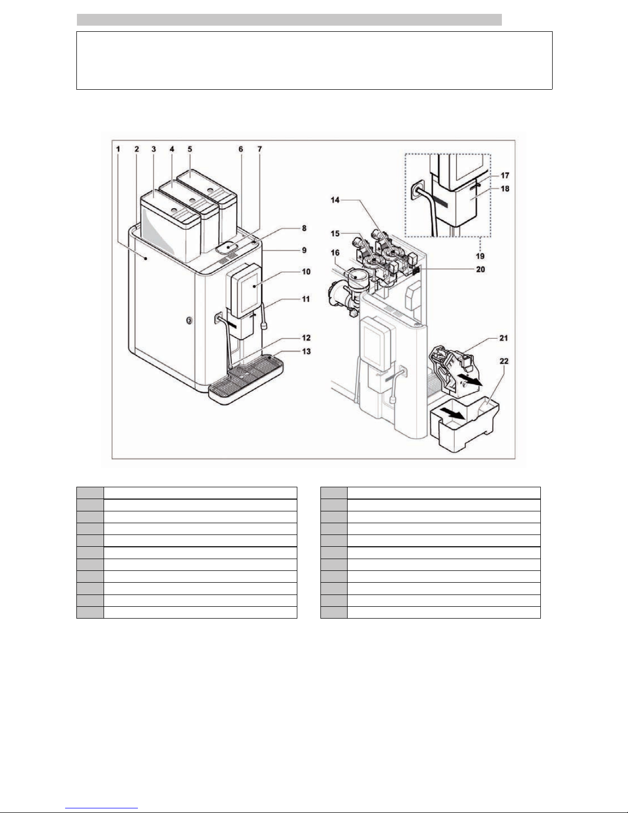
MAIN PARTS
Nextage Main Parts
1 Left hand side panel 12 Steam wand
2 Back panel 13 Drip Tray
3 Instant product container 14 Coffee grinder/right dosing unit group
4 Left coffee bean hopper 15 Coffee grinder/left dosing unit group
5 Right coffee bean hopper 16 Mixer
6 Right hand side panel 17 Milk crema adjusting device
7 Pre-ground coffee door 18 Dispenser cover
8 Door lock 19 Dispenser
9 Door 20 Power button
10 Control panel 21 Coffee Group
11 Hot water wand 22 Dump box
Page 4

English
48
CONTENTS
MAIN PARTS
47
1 INTRODUCTION TO THE MANUAL
49
1.1 INTRODUCTION
49
1.2 SYMBOLS USED
49
2 INFORMATION ABOUT THE MACHINE
50
2.1 NOTES FOR THE USER
50
2.2 INTENDED USE OF THE APPLIANCE
50
2.3 APPLIANCE IDENTIFICATION
50
2.4 TECHNICAL DATA
51
3 SAFETY
52
3.1 INTRODUCTION
52
3.2 GENERAL SAFETY REGULATIONS
52
3.3 OPERATORS' REQUIREMENTS
53
3.4 SAFETY DEVICES
53
3.5 RESIDUAL RISKS
53
4 HANDLING AND STORAGE
54
4.1 UNLOADING AND HANDLING
54
4.2 STORAGE
54
5 INSTALLATION
55
5.1 WARNING
55
5.2 UNPACKING AND POSITIONING
55
5.3 CONNECTION TO WATER MAINS
57
5.4 CONNECTION TO THE ELECTRIC NETWORK
58
5.5 MOUNTING THE SPOILERS
58
5.6 CONNECTING THE USB PORT
59
6 DESCRIPTION OF CONTROLS
61
6.1 COMMANDS
61
7 SUPPLY AND STARTING UP
62
7.1 CONTAINER CONFIGURATION
62
7.2 COFFEE BEAN SUPPLY
62
7.3 REFILLING WITH PRE-GROUND COFFEE
62
7.4 INSTANT PRODUCT SUPPLY
63
7.5 CREAM ADJUSTMENT
63
7.6 TEMPERATURE SETTING
63
7.7 COFFEE GRINDING CALIBRATION
64
7.8 FIRST START-UP OF THE MACHINE
65
7.9 CLEANING THE PARTS IN CONTACT WITH
FOODSTUFFS
67
7.10 USE OF THE MACHINE
67
8 MAINTENANCE MENU
68
8.1 MAINTENANCE MENU
68
9 OPERATION AND USE
70
9.1 SWITCH ON
70
9.2 BEVERAGE SELECTION
70
9.3 DISPLAY MESSAGES
72
9.4 MACHINE SWITCHING-OFF
73
10 CLEANING AND MAINTENANCE
74
10.1 GENERAL NOTES FOR CORRECT OPERATION
74
10.2 CLEANING AND SCHEDULED MAINTENANCE
74
10.3 NON-SCHEDULED MAINTENANCE
85
11 TROUBLESHOOTING
86
12 STORAGE DISPOSAL
87
12.1 CHANGE OF LOCATION
87
12.2 INACTIVITY AND STORAGE PERIODS
87
13 INSTRUCTIONS FOR END-OF-LIFE
DISPOSAL TREATMENT
88
Page 5
English
1
49
1 INTRODUCTION TO THE MANUAL
1.1 Introduction
This manual is an integral part of this machine and it
must be kept in a handy place, in good conditions, for
as long as the machine will be operating (including any
transfer of ownership). Il suo fine, è la trasmissione
delle informazioni necessarie all’uso competente e
sicuro della macchina stessa.
In case of lost or deterioration of this brochure, please
ask a copy to the Authorized customer Service
Center, specifying the model and the year of
construction of your machine.
The Authorized Customer Service Centers, are also
available for any technical explanation, information on
its operation, technical assistance and spare parts
supply.
The subjects mentioned aim, in an exclusive way, at
ensuring the proper use of the machine, in the safest
way for users, the very machine and the environment.
This is made through a simple diagnostics of troubles
and anomalous functioning, and by carrying out some
simple checks and maintenance operations, always
respecting the precautions explained in the following
pages and the current Safety and Health Regulations
Before any intervention read very carefully and be sure
to have completely understood the subject of this
brochure.
If several persons use (individually) this machine,
everyone must previously and very carefully study the
Instruction Manual.
The manufacturer reserves the right to modify and
improve the described models, without being bound
to give any notice.
For any particular need contact the Distributor or
your Country Importer (if any) or the Constructor.
All the rights of this brochure are reserved to SAECO
Vending S.p.A.. Any copy or even partial divulgation,
not expressively authorized in writing, are strongly
forbidden.
Always refer to this publication before carrying out any
operation.
Manufacturer: SAECO Vending S.p.A.
Località Casona, 1066 40041 Gaggio Montano
Bologna, Italy
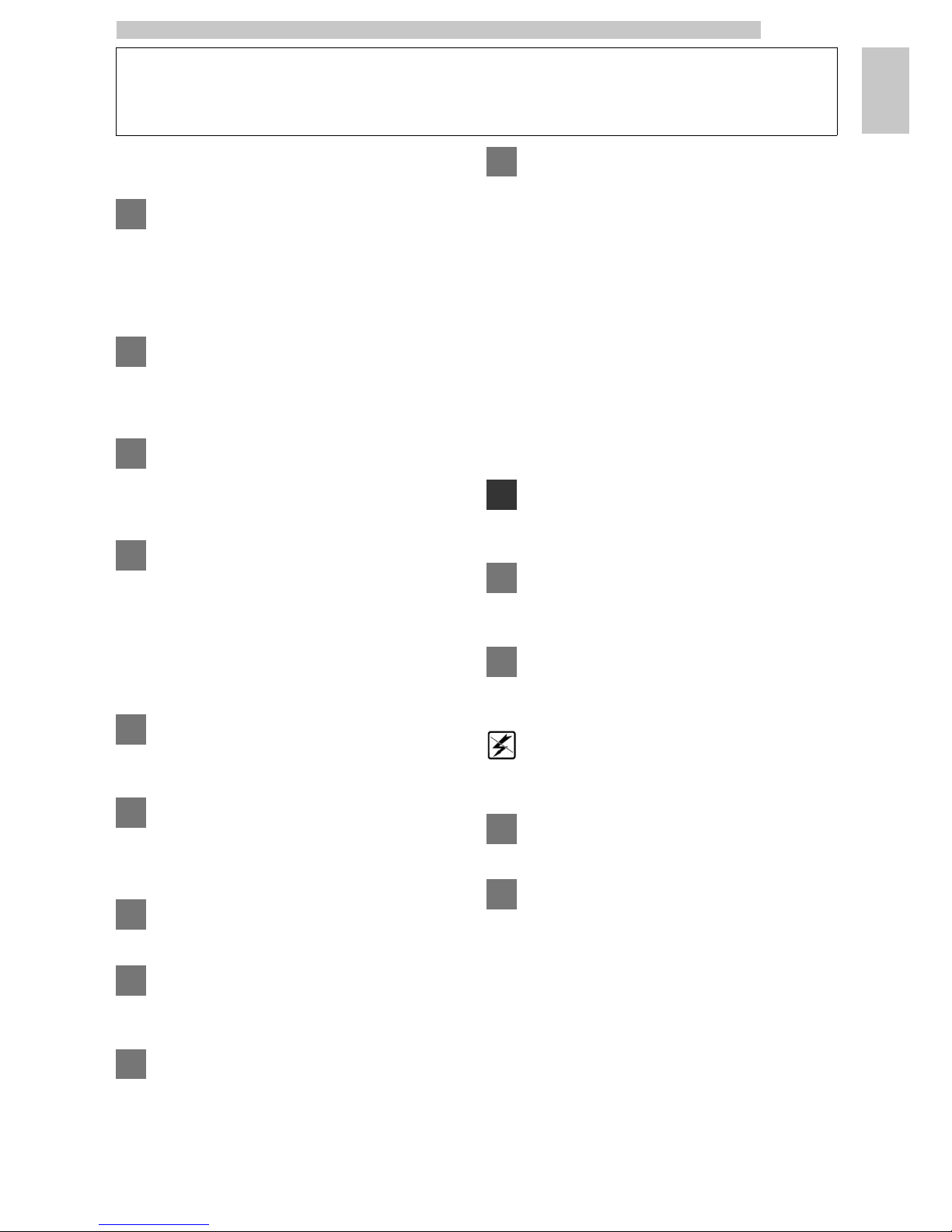
1.2 Symbols used
This publication contains various warnings which indicate
different degrees of danger or skills required.
Alongside the graphic symbol, a message will define the procedures to be
adopted and all useful information will be detailed.
Warning
Information about the user’s safety and the machine
integrity.
Prohibition notice
It is used to highlight actions/operations not to be
performed.
Important
It draws the attention on a particularly important subject.
Machine off
Operations to be done without power supply .
User
Actions concerning the machine user.
Maintenance Technician
Operations strictly concerning personnel in charge of
unscheduled maintenance or repairs.
Page 6
English
2
50
2 INFORMATION ABOUT THE MACHINE
2.1 Notes for the user
The appliance must be installed in a properly lighted,
sheltered and dry location and on a working surface able
to withstand its weight.
To guarantee the correct operation and reliability over
time, the following is recommended:
• ambient temperature: from +1°C to +25°C;
• maximum humidity: 90% (not condensed).
For special installations not covered in this publication,
please contact the dealer or the local importer. If this is
not possible, please contact the Manufacturer directly.
For all possible requirements, always refer to the Distributor or
Importer for each Country. If a specific Country has no
Importer, recourse should be made directly to the Manufacturer.
The Manufacturer’s maintenance service is available to
clarify any doubts concerning the correct operation of the
appliance.
In case of damages to the power cable, it must be replaced
by the Manufacturer or by its Technical Assistance Service,
or alternatively, by a person with similar qualifications.
The AUTHORISED SERVICE CENTRE is available for any
type of explanation and information pertaining to appliance
operation and to satisfy requests for the supply of spares
or technical assistance.
The Manufacturer reserves the right to introduce further
improvements to the appliance without notice.
All rights of reproduction of this manual are reserved by
the Manufacturer.
The Maintenance Technician must carefully read and
respect the safety warnings contained in this manual so
that every intervention concerning installation, starting up,
use and maintenance will be safely carried out.
2.2 Intended use of the appliance
The machine is intended for the brewing of coffee and hot
beverages (decaffeinated coffee, cappuccino, chocolate,
etc.). The dosage of each type of brewing can be
programmed. Instant products must be consumed right
after the brewing and cannot be stored for long.
Any other use is to be considered improper and therefore
dangerous.
Do not place any product inside the machine which
may be dangerous as a result of unsuitable
temperatures.
Improper use of the vending machine invalidates all
warranties. The Manufacturer declines any liability for
damage to property or injury to persons.
Improper use also includes:
• any use of the vending machine other than the intended
use and/or according to procedures which are not
described in this publication;
• any intervention on the appliance contrasting with the
indications referred to in this manual;
• any alteration of components and/or safety devices
without prior consent of the Manufacturer or carried out
by personnel not authorized for such operations;
• any location of the vending machine not provided in this
manual.
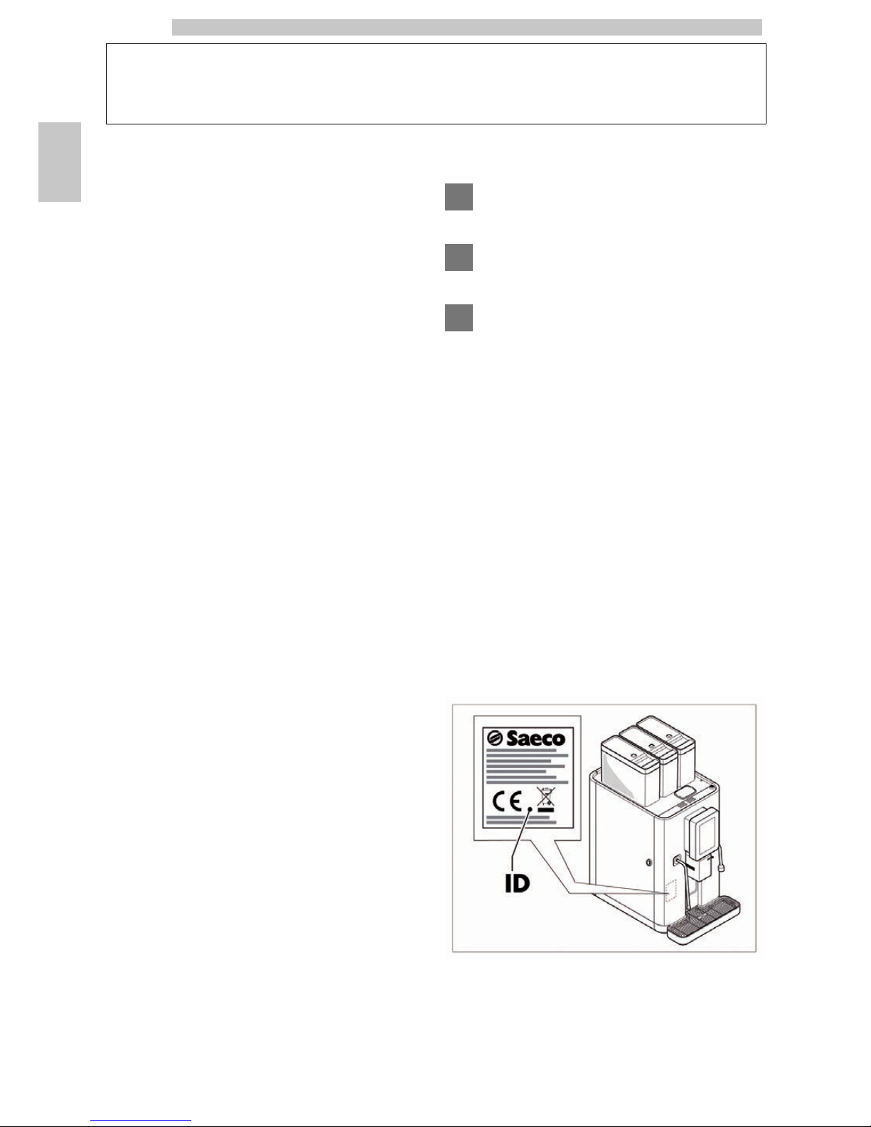
2.3 Appliance identification
The appliance is identified by the model name and serial
number shown on the special plate.
ID Data plate
Page 7
English
2
51
The following data can be found on the plate:
• name of Manufacturer;
• marks of compliance;
• model;
• serial number;
• year and month of manufacture;
• supply voltage (V);
• supply frequency (Hz);
• electrical power consumption (W).
• number of phases of the electric line (PH);
• pressure allowed in the water network (MPa);
It is strictly forbidden to tamper with or modify the
data plate.
When contacting the technical service, always refer to
this plate by indicating the technical data shown on it.
In case of any request to the Authorized Customer Service
Centers, model and serial number must be specified.
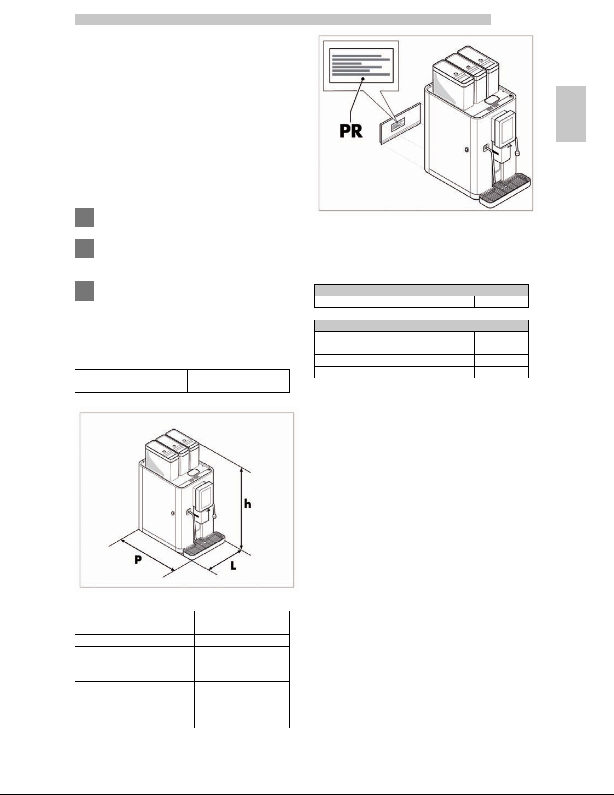
2.4 Technical data
Dimensions (w x h x d) 364 x 790 x 596 mm
Weight 60 kg
Power consumption see data plate
Supply voltage see data plate
Electric voltage frequency see data plate
Power cord length 3,000 mm
Water mains connection 3/8"
A-Weighted sound pressure
level
less than 70 dB
Water mains pressure
See the pressure data
plate
PR
Data plate showing minimum and maximum water
supply pressure
Container capacity
Bean hopper capacity
Coffee beans 1,3 kg
Instant product container capacity
Tea 1,5 kg
Hot Chocolate 1,75 kg
Barley 0,33 kg
Freeze-dried coffee 0.3 kg
Page 8
English
3
52
3 SAFETY
3.1 Introduction
According to the low voltage Directive 2006/95/EC
(substituting Directive 73/23/EEC and following
amendments) and the CE marking Directive 93/68/EEC,
SAECO VENDING has arranged for a NextAge technical
file at its premises, thus transposing the following
standards during the designing phase:
- EN 55014 - EN 61000-4-4
- EN 6100-3-2 - EN 61000-4-5
- EN 61000-3-3 - EN 61000-4-11
- EN 61000-4-2 - EN 60335-2-75
- EN 61000-4-3 - EN 60335-1
3.2 General safety regulations
It is forbidden to:
• disable the safety devices installed on the appliance;
• carry out maintenance on the machine without
unplugging it first;
• Install the appliance outdoors. It is advisable to place it in a
dry place where the temperature does not drop below
1°C, in order to prevent any possible freezing.
• use the machine for purposes other than those indicated
in the sale contract and in this publication;
• connect the appliance to the mains using multi-sockets or
adapters;
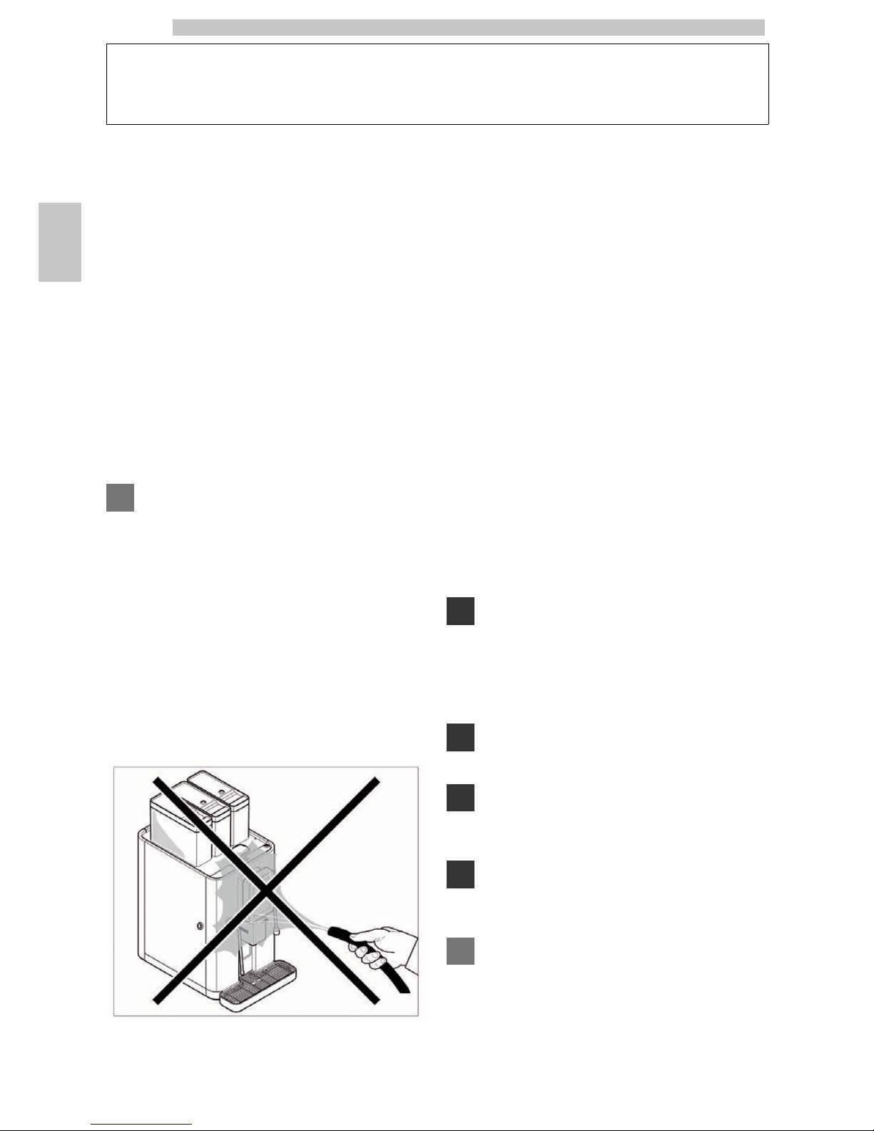
• use water jets to clean the vending machine.
It is compulsory to:
• check the electrical power line for conformity;
• use original spare parts;
• read the instructions contained in this publication and in
the enclosed documents carefully;
• use personal protection devices during installation, testing
and maintenance operations;
• Use a new water network connection set each time the
machine is disconnected and connected again to the
system.
Precautions for preventing human errors:
• make the operators aware of safety issues;
• handle the machine, either packaged or unpackaged, in
safe conditions;
• have a thorough knowledge of the installation procedures,
its operation and limits;
• dismantle the machine in safe conditions, in accordance
with the environmental protection and health and safety
laws in force.
To prevent machining residues from coming into
contact with the beverages, dispense about 0.5 l water
for each dispensing path before definitely starting the
vending machine. The dispensed beverages can be
consumed only after performing this operation.
Do not install the appliance in a location where water
jets may be used.
The appliance must only be installed in places where it
can be used and maintained only by qualified staff.
In case of failure or malfunctioning, please refer only to
the qualified personnel of the technical service.
The Manufacturer declines any liability for any damage
caused to property or injury caused to persons as a
result of failure to observe the safety regulations
described here.
Page 9
English
3
53
3.3 Operators' requirements
Two operators with different skills are required in order
to guarantee the appliance’s safety:
User
Person in charge of using and attending the machine. The
user is allowed to: Operate the appliance, adjust the
operating parameters, stop the appliance, refill the
appliance with coffee and instant products, empty the
liquid collection tray and the coffee grounds drawer, clean
the outside of the appliance. On detection of appliance
malfunctions, the User must request the assistance of the
Maintenance Technician.
The User is not allowed to carry out operations
indicated in this manual as competence of the
Maintenance Technician.
Maintenance Technician
Person in charge of installation, adjustment, set-up and, in
general, maintenance operations on the machine.
Access to the service area is restricted to persons having
knowledge and pratical experience of the appliance, in
particular as far as safety and hygiene are concerned.
3.4 Safety devices
The machines described in this brochure are in
conformity with the specific current European
Regulations and therefore all their potentially
dangerous parts are protected.
Any overpressure in the water system that produces
steam and hot water is detected by 3 safety valves.
A thermostat avoids boilers overheating.
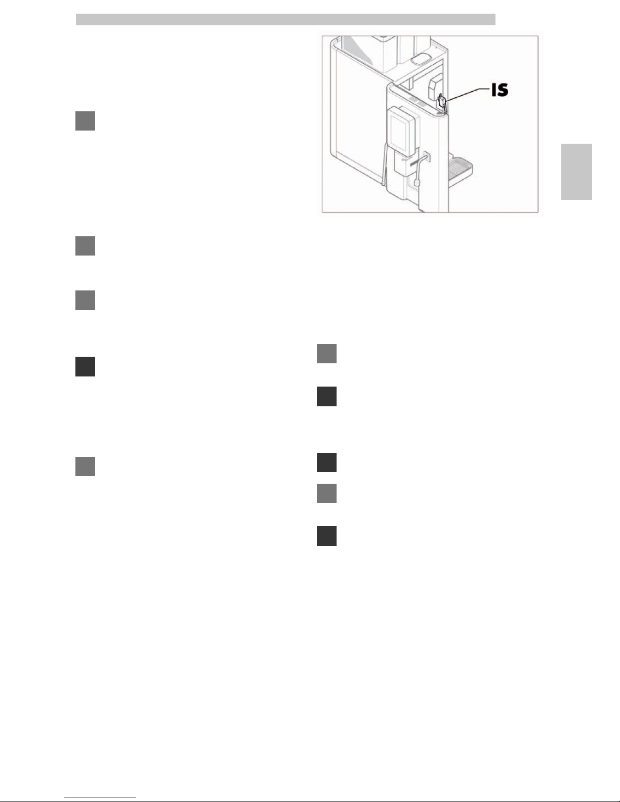
The door position is controlled by 1 microswitch that
stops machine operation when the component is not
placed correctly.
IS Safety switch
An electronic pulse counter stores the number of brewing
procedures performed and allows the scheduled
maintenance to be programmed.
3.5 Residual risks
Do not use containers that are not made of food
materials.
The structural characteristics of the machines
described in this brochure, do not protect the user
from the direct steam or hot water spouts.
Danger of burns.
During hot water and steam brewing do not turn the
spouts towards yourself or someone else.
Grab the spout only by the respective anti-burns
protectors.
Page 10
English
4
54
4 HANDLING AND STORAGE
4.1 Unloading and handling
Unloading from the transport vehicle and handling
operations of the appliance must be carried out by
qualified personnel only and using suitable equipment.
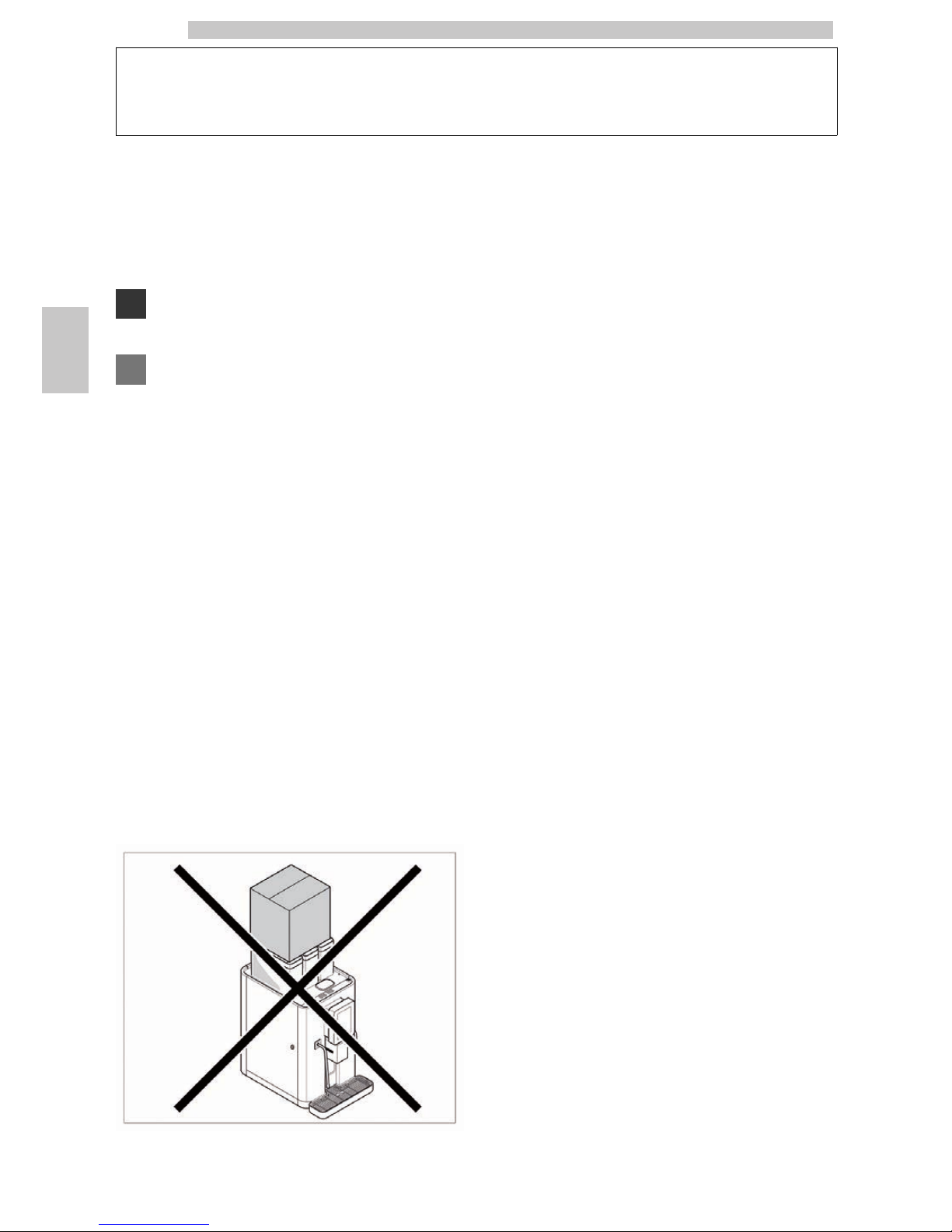
The appliance must always be kept in upright position.
Avoid:
• dragging the appliance;
• Overturn or lay down the appliance during transport and
handling;
• shaking the appliance;
• lifting the vending machine with ropes or cranes;
• leaving the appliance exposed to the elements, in humid
areas or close to heat sources.
4.2 Storage
If the appliance is not installed within a short time, but is
to be stored for a long time, it shall be kept in a sheltered
place according to the following instructions:
• the packaged appliance shall be stored in a closed, dry
area at a temperature between 1°C and 40°C;
• do not put other appliances or boxes on the appliance;
• in any case, it is good practice to protect the appliance
from possible deposits of dust or other substances.
Page 11
English
5
55
5 INSTALLATION
5.1 Warning
The appliance cannot be installed in external areas.
Avoid installing it in areas where the temperature is
lower than +1°C or higher than 25°C and in
particularly humid or dusty places and it should not be
installed in places subject to explosion or fire hazards,
or where cleaning is done with water jets.
Before unpacking, check that the installation area complies
with the following specifications:
• the electric socket which the appliance is connected to
must be easily accessible for the user, so that the user will
easily disconnect the appliance from the electric mains
when necessary;
• the socket voltage must comply with that on the
identification plate;
• the maximum angle of inclination of the supporting
surface must NOT exceed 2°.
Check if the surface where the machine is installed has
the adequate dimension and solidity to support the
machine safely.
For a correct and ergonomic use of the machine, it is
recommended to install it onto a surface which is at
least 1 m high.
The appliance must be installed on a horizontal
surface.
The appliance must only be installed in places where it can
be used and maintained only by qualified staff.
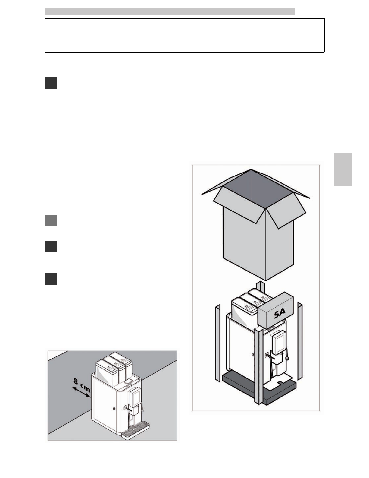
If the appliance needs to be positioned close to a wall, it is
necessary to leave a space of at least 8 cm between the
appliance’s back and the wall in order to make sure that
the air outlet grill at the back of the appliance is
unobstructed.
5.2 Unpacking and positioning
On receipt of the appliance, make sure that it has not
suffered any damage during transport or that the packaging
has not been unduly opened with consequent stealing of
the components contained in it.
If damage of any kind is found, the courier must be
informed and notice must be given to the importer or the
seller immediately.
If these are not in the purchaser’s country, please contact
the manufacturing company directly.
The appliance is protected by 4 angle bars and a plastic bag
and is delivered in a box.
Page 12
English
5
56
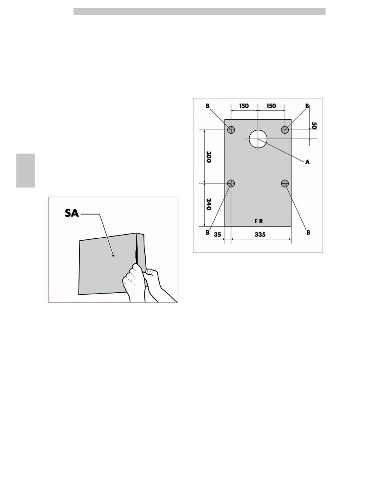
The appliance is supplied with an “ACCESSORY BOX”
that contains the following items:
• Instruction booklet
• Drip tray
• Rear spoiler
• No. 2 side spoilers
• Filling tube
• Drain tube
• Metal clamp
• Silicone hose
• Scraper
• No. 2 small brushes
• Measuring scoop
• Cleaning brush
• Detergent
• Grease tube
• Door key
SA Accessory box
Check that the surface where the appliance shall be
positioned is steady.
Make a 100 mm Ø hole on the surface (hole A in the figure).
Install the machine in its final position on the supporting
surface (the rings B indicate the ideal position of the
adjustable feet).
Level the machine by setting the adjustable feet.
FR Machine front side
A Hole to be made
B Ideal position of the adjustable feet
Page 13
English
5
57
5.3 Connection to water mains
Before connecting the appliance to water network,
please read and follow the applicable regulations in
force in your country.
Make sure the water network provides drinkable
water, with pressure ranging between 0,15MPA =,8MPA (1,5 and 8 bars).
Water hardness should not be less than 8°F.
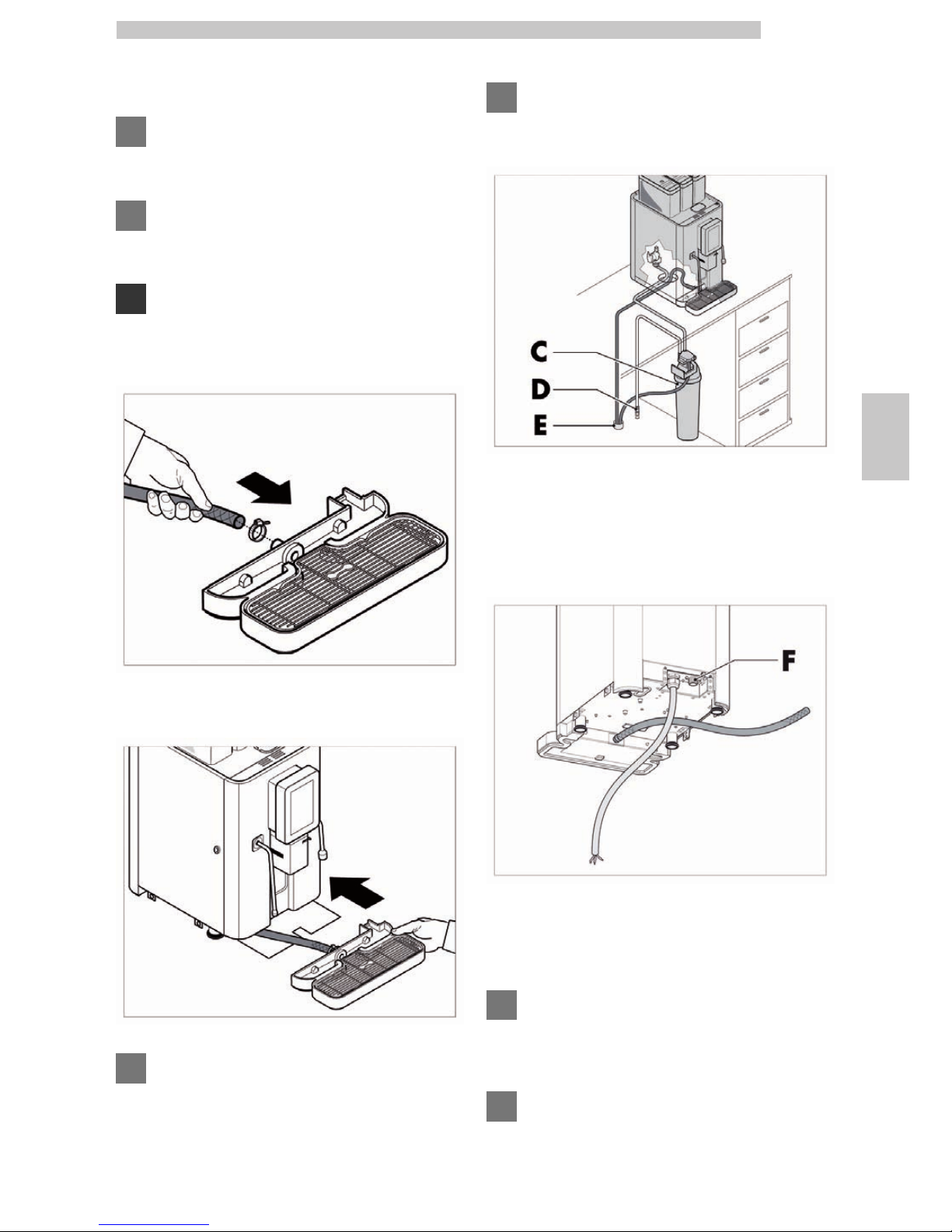
Use the metal clamp to connect the drain tube to the drip
tray.
Insert the drip tray into the machine front.
We recommend that the machine be supplied with
water treated by a descaling device, particularly for
water with high content of calcium and magnesium
(hard water).
Connect the water filter (C) to the water network (D).
Before connecting the water softener to the machine,
wash the machine until the water is clear.
C Water Filter
D Water network
E Drain channel
Connect the machine to the drinking water network by
means of the coupling (F). Only a tube and couplings
suitable "for food" must be used for the connection.
F Water inlet coupling
Insert the filling tube and the drain tube into the hole A.
Connect the drain tubes to the drain pipe (E).
Should the machine be moved to a different place, the
fitting unit must be replaced with a new one (water
network connecting pipe).
The water mains pipe should be certified according to
the standard IEC 61770.
Page 14
English
5
58
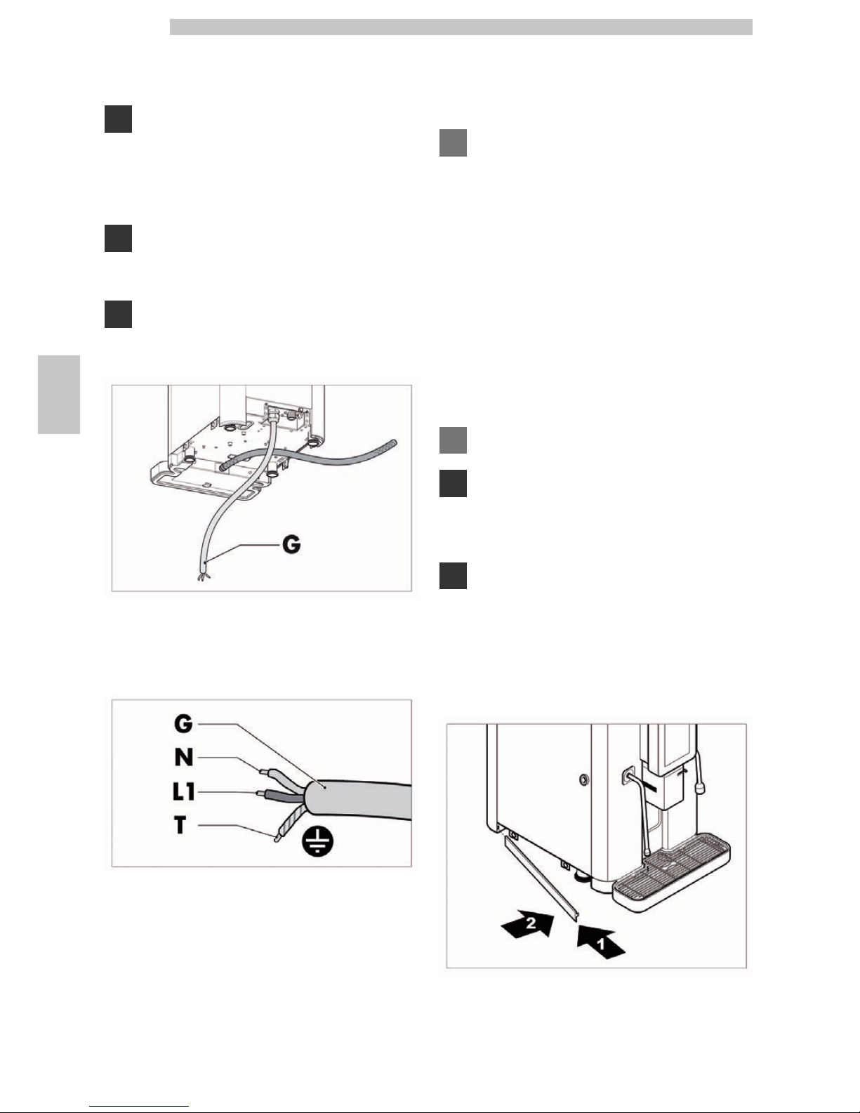
5.4 Connection to the electric
network
The Maintenance Technician, who is responsible for
the installation of the machine, must ensure that:
• the electric system complies with current safety
regulations;
• the supply voltage corresponds to that indicated on the
data plate.
If in doubt, do not proceed with the installation and
ask qualified and authorized personnel to check the
system accurately.
Also make sure that the electrical system the appliance
is connected to has the maximum load capacity
required, as indicated on the data plate.
G Power cord type H07RNF sec. 3x2.5 mm²
Insert the power cord (G) into the hole A.
G Power cord type H07RNF sec. 3x2.5 mm²
N Neutral
L1 Phase
T Ground
Depending on the current regulations of the Country
where the machine operates, the cable connecting the
electric line has to be pre-set or equipped with an
all-pole switch (with a minimum contact opening of 3
mm), (or with a plug in accordance with the same
regulations).
• The all-pole switch must suit to machine input and be able
to detect all voltage polarities.
• Check that the electrical cables of the system are
proportioned to machine input.
Connect the appliance to the mains by means of the
power cord (G).
Make sure that the electrical plug is easily accessible
even after installing the machine.
The electric socket which the appliance is connected
to must be easily accessible for the user, so that the
user will easily disconnect the appliance from the
electric mains when necessary.
If damaged, the power cable must be replaced by the
Maintenance Technician only.
5.5 Mounting the Spoilers
Insert the left side spoiler as shown in the figure.
Do the same for the right side spoiler.
Page 15

English
5
59
Insert the rear spoiler as shown in the figure.
5.6 Connecting the USB Port
The USB port can be used to connect the machine to the
AUTHORISED SERVICE CENTRES' appliances in order to
carry out checks and programming operations.
To access the USB port perform the following operations.
Each operation via USB port must be carried out with
the door closed.
Loosen the socket head screw that is placed on the back
of the control panel.
Slide the control panel upwards.
Now the control panel is not attached to the machine any
more and should be removed as shown in the figure.
Attach the pins I to the suitable guides M as shown in the figure.
I Control panel pin
M Control panel guide
Page 16

English
5
60
Turn the control panel as shown in the figure.
Remove the cap from the inner side of the control panel
and connect to the USB port Q.
Q USB port
Page 17

English
6
61
6 DESCRIPTION OF CONTROLS
6.1 Commands
The appliance has the following controls:
• Power button
• Control panel
6.1.1 Power button
When the machine is connected to the mains and the
all-pole switch is set to "I", the following happens when
operating the power button:
• Power button set to "0", the control panel is off.
• Power button set to "I", the control panel is on.
The fact that the power button is set to "0" does not
represent a guarantee that the machine is not powered.
When performing any kind of cleaning or maintenance
intervention involving the inside of the machine,
disconnect the machine from the mains and set the
all-pole switch to "0".
6.1.2 Control panel
The control panel is sensitive to the touch, i.e. it combines
the functions of a display with those of a keypad.
The display areas which are sensitive to the touch change
according to the current machine phase, e.g. standard
operation or maintenance.
Page 18

English
7
62
7 SUPPLY AND STARTING UP
7.1 Container Configuration
The containers delivered are designed to dispense the
following products:
Instant product NextAge
1 Coffee beans
2 Coffee beans
3 Hot Chocolate
4 Pre-ground Coffee
7.2 Coffee bean supply
Be sure the coffee does not contain foreign bodies
which could be dangerous for grinders.
Remove the container cover.
Put coffee beans into the container.
Replace the cover on the container.
The appliance has two coffee bean hoppers, which
means that two different types of coffee can be used.
7.3 Refilling with Pre-ground Coffee
This operation can only be performed with the
machine switched on.
Open the pre-ground coffee door.
The machine will detect that the door is open and will
disable the coffee grinders/dosing units under the coffee
bean hoppers.
A "heart" icon will be displayed on the pictures of the
coffee-based beverages; this means that pre-ground coffee
is currently being used.
Pour the pre-ground coffee (max 2 measuring scoops) into
the duct.
Select the desired pre-ground coffee-based product
and leave the pre-ground coffee door open.
If the coffee-based beverage is selected with the door
closed, the machine will enable the coffee
grinders/dosing units' operation and a double dose of
coffee will be used (pre-ground coffee dose + fresh
ground coffee dose). As a result, nothing will be
brewed.
When the operations involving the use of pre-ground coffee are
complete, close the door. The coffee grinders/dosing units will be
enabled again and the "heart" icons will disappear from the
pictures of the coffee-based beverages.
Page 19

English
7
63
7.4 Instant product supply
Open the door.
Press the retainer FC in order to unlock the external
cover.
Remove the external cover from the instant product container.
Open the cover of the instant products container.
Pour the instant product into the container.
Close the container cover.
Refit the external cover.
Close the door.
7.5 Cream adjustment
Cream quantity is adjusted through lever.
By turning the lever clockwise, there will be a greater
quantity of cream.
By turning the lever anti-clockwise, there will be a smaller
quantity of cream.
7.6 Temperature setting
The milk to be used for the Cappuccinatore must be
put in a fridge at a temperature not over 4° C; do not
leave it outside the fridge for more than 30 minutes.
To change the milk temperature remove the dispenser
cover and operate the temperature adjusting lever.
Page 20

English
7
64
• By turning the lever upward, the temperature will grow.
• By turning the lever downward, the temperature will
lower.
7.7 Coffee grinding calibration
Whatever the coffee blend is, a very fine grinding
(notch on low values) increases the density, the cream
quantity and the brewing time of the beverage. On the
contrary a coarse grinding (notch on high values)
decreases the density, the cream, as well as the
brewing time.
Should a blockage of the grinders occur because
foreign bodies contaminated the coffee blend thus
blocking the machine, please contact an Authorised
Service Centre. When such blockage occurs, the "no
coffee" icon is displayed on the beverage pictures.
If either coffee grinder blocks, the operational one can
be selected from the control panel, so as to avoid
machine downtime. This operation is allowed only if
the product recipe does not specify which coffee
grinder should be used.
The grinding is pre-set to standard values, which anyway
can be modified with the following procedure.
Switch on the machine as instructed in the "First Appliance
Start Up" section.
Press the "Customer menu" button.
Press the "Maintenance" writing.
Page 21

English
7
65
Press the "Coffee grinder" writing.
From this screen you can select which one of the two
coffee grinders you want to set.
After selecting the coffee grinder, press "Finer" to set a
finer grind (the value becomes lower), or "Coarser" to set
a coarser grind (the value becomes higher).
Press "Back" to return to the previous menu.
To exit the maintenance menu and return to the beverage
selection screen, press the bottom left arrow and wait for
a few seconds.
The effects of the grind adjustment will become
noticeable after brewing 2-3 cups of coffee.
7.8 First start-up of the machine
Check if the removable components are in the right
position and if the door is closed.
If this is not the case, an indication of the component that is in
the wrong position will be displayed upon beverage selection.
Refill the machine (follow the instructions above) and
connect the appliance to the water network (see section
"Connection to the Water Network") and to the mains
(see section"Connection to the Electric Network").
Turn the all-pole switch on “I”.
Page 22

English
7
66
Open the door and switch on the machine by means of
the power button.
Close the door.
The following screen is displayed on the control panel.
Wait for a few seconds without touching the control
panel.
When the switch-on phase is complete, the following beverage
selection screen is displayed on the control panel.
No beverage will be brewed and no icon will be
enabled until the boilers reach the operating
temperature.
At the end of the warm-up phase the machine carries out
the "Machine ready" cycle.
At this point the icons of the beverages will be enabled.
Page 23

English
7
67
During the "Machine ready" cycle the machine will
dispense hot water and steam, so make sure you do
not put your hands under the jets.
7.9 Cleaning the parts in contact
with foodstuffs
Clean all the parts of the VM which are in contact with
foodstuffs.
• Wash your hands carefully.
• prepare a chlorine-based anti-bacterial cleaning solution
(these products can be purchased at the chemist’s)
following the concentrations indicated by the product
instructions.
• remove all the product containers from the machine.
• Remove the container lids and the product channels.
Plunge all items into the previously prepared solution.
7.10 Use of the machine
The beverage selection mode is indicated in chapter
"Operation and Use".
Page 24

English
8
68
8 MAINTENANCE MENU
This section contains instructions on how to set and
change the maintenance parameters of the appliance.
It is therefore necessary to read it carefully, and
intervene only when the correct sequence of
operations to be performed is fully understood.
8.1 Maintenance menu
The structure of the maintenance menu is indicated in
section “Structure of the Maintenance Menu”.
The section “Description of Messages in the Maintenance
Menu” describes all the entries in the maintenance menu.
8.1.1 Access to the maintenance menu
Follow the instructions listed below in order to enter the
maintenance menu.
Switch on the machine as instructed in the "First Appliance
Start Up" section, wait for the start-up screen to appear
and then press the "Customer menu" button.
Press the "Maintenance" writing.
To exit the maintenance menu and return to the beverage
selection screen:
• Press the bottom left arrow and wait for a few seconds.
• Close the door.
Page 25

English
8
69
8.1.2 Structure of the maintenance menu
ITEM NO. MENU ITEM
1 MAINTENANCE
1.1. Cleaning
1.1.1. Coffee Group
01:01:02 Dispensing spout/mixer
01:01:03 Milk circuit
1.2. Coffee grinder
1.2.1. Coffee grinder 1/2
1.2.1.1. Finer
1.2.1.2. Coarser
8.1.3 Description of messages in the maintenance menu
DISPLAY Description
1
MAINTENANCE
This menu allows some maintenance and cleaning operations to be performed on some
internal machine parts.
1.1.
Cleaning
This option allows the brew group, dispensing spout, mixer and milk circuit to be washed.
1.1.1.
Coffee Group
This option allows a brew group wash cycle to be performed (see section "Brew Group
Cleaning").
01:01:02
Dispensing spout/mixer
This option allows a wash cycle of the dispensing spout and of the instant product mixer to
be performed (see section "Cleaning the Dispensing Spout and the Instant Product Mixer").
01:01:03
Milk circuit
This option allows a milk circuit wash cycle to be performed (see section "Milk Circuit
Cleaning").
1.2.
Coffee grinder
This option allows the coffee grinders' grind to be adjusted (see section "Coffee Grind
Adjustment").
1.2.1.
Coffee grinder 1/2
This option allows the user to select the coffee grinder to which the coffee grind adjustment
should be applied.
1.2.1.1.
Finer
This option allows for a finer grind.
1.2.1.2.
Coarser
This option allows for a coarser grind.
Page 26

English
9
70
9 OPERATION AND USE
Read carefully this brochure until you get a good
understanding of the machine, before starting to
operate it.
After a long time of machine inactivity, read the
paragraph “First switching-on” before re-operating the
machine.
This appliance is not intended for use by persons
(including children) with reduced physical, sensory or
mental capabilities, or lack of experience and
knowledge, unless they have been given supervision or
instruction concerning use of the appliance by a
person responsible for their safety.
Children must be supervised to ensure they do not
play with the appliance.
This appliance is to be used for household applications
or in similar areas like:
• For staff only cooking areas in shops, offices and other
professional environments;
• Farms;
• For clients use in hotels, motels and other residential type
areas;
• Environments like bed and breakfasts.
9.1 Switch On
Proceed as explained in paragraph "First switching-on".
9.2 Beverage selection
The following are the conditions necessary to select a
beverage:
• After the switch-on procedure the machine has reached
the set temperature. If not, the beverage icons will be
disabled and the message "'Beverage name' not ready" will
be displayed when touching the corresponding icon.
• There is no error condition that prevents the brewing of
beverages. If this is not the case, the icons corresponding
to the beverages in error will be disabled, and the error
message will be displayed when touching these icons.
• The selected beverage is enabled. If not, the beverage icon
will be disabled, and a message describing the cause of
beverage unavailability will be displayed when touching the
icon.
• The selected beverage is not locked. If this is not the case,
the beverage icon will be disabled and a message
displaying the locking condition will be displayed when
touching the corresponding icon.
Beverage selection
If the necessary conditions for beverage selection are met
the following screen will be displayed on the machine. If
not, some icons might be disabled.
The first 4 lines contain the selectable beverages.
The last line contains the icon for the selection of the
coffee bean hopper to use, the icon to adjust the height of
the dispensing spout and the icon of the beverage
multiplier.
Page 27

English
9
71
Selecting the Coffee Bean Hopper
This control allows the user to select which coffee bean
hopper he/she would like to use to brew the coffee
bean-based beverage.
This selection is available only if the machine is
equipped with 2 coffee bean hoppers.
This selection is available only if the recipe of the
selected beverage does not specify the coffee bean
hopper to use.
The following picture shows the two available options: The
one on the left indicates that the left coffee bean hopper is
being used, the one on the right indicates that the right
coffee bean hopper is being used.
Adjusting the Height of the Dispensing Spout
If the machine is programmed to allow the dispensing
spout height to be adjusted, the icon shown in the
following picture will be visible on the display.
This control allows the dispensing spout to be adjusted at various
heights so that glasses of different sizes can be used.
The picture below shows the minimum and maximum
heights possible.
h1 70 mm
h2 200 mm
Beverage Multiplier
This control allows the user to multiply the number of
beverages to be brewed.
Every time the icon shown in the figure is pressed, the
counter increases by 1 unit from a minimum of 1 to a
maximum of 8 beverages.
After pressing the multiplier icon, only the beverages
programmed for being multiplied will still be enabled.
If no beverage icon is pressed within 5 seconds after
pressing the multiplier icon, the counter is reset to 1.
During the beverage brewing, the number of the
current brewing process and the total number of the
required beverages is displayed.
Beverage Brewing
To brew a beverage press the icon corresponding to the
required beverage.
During the beverage brewing, a screen with the following
layout is displayed:
• On top, the product brewing bar.
• In the middle, the picture of the beverage being brewed in
that moment.
Page 28

English
9
72
• On the left bottom side, a button to stop the beverage
brewing.
• On the right bottom side, a button to stop the current
phase and go on with the subsequent phases.
The figure shows the "Cappuccino" brewing screen.
If an anomalous condition occurs during the brewing
phase, e.g. a fault or a product shortage, a message
with the causes of the block is displayed.
Special messages and signals are indicated in chapter
"Troubleshooting".
9.3 Display messages
When one or more alarms occur, the relevant beverages
are disabled and cannot be selected for the brewing.
If a disabled beverage is pressed a timed pop-up window
appears for 3 seconds, indicating which current alarm has
disabled the beverage.
Here below the list of the alarms displayed is reported,
along with the machine conditions that release them.
Temperature sensor alarm
Consequence: All the beverages for which the coffee
phase is required are disabled.
Message upon touching: "Temperature sensor alarm".
Pressure sensor alarm
Consequence: All the beverages for which the water phase, the
milk phase or the steam phase is required are disabled.
Message upon touching: "Pressure sensor alarm".
Coffee grinder 1(2) blocked
Consequence: If the selected coffee grinder is blocked all
the beverages for which the coffee phase is required are
disabled; if the blocked coffee grinder is not the selected
one, the error has no consequences.
Note: In machine models which allow for the coffee bean
hoppers to be used alternatively, the blocked coffee
grinder is just not used.
Message upon touching: "Coffee grinder blocked".
Coffee alarm
Meaning: The latest grinding cycle exceeded the timeout.
Possible causes: There is no coffee; the dosing unit sensor
is out of order or disconnected (after 5 attempts).
Consequence: The "no coffee" icon is shown over the beverages
for which the coffee phase is required with either the coffee
beans from the empty hopper or the not operational dosing unit.
Message upon touching: No message.
Water alarm
Meaning: No water pressure detected.
Consequence: All beverages are disabled.
Message upon touching: "No water".
Water level alarm
Consequence: All the beverages for which the steam phase, the
milk phase or the hot water phase is required, are disabled.
Message upon touching: "Water level error".
Brew group error
Consequence: All the beverages for which the coffee
phase is required are disabled.
Message upon touching: "Brew group error".
Coffee grounds drawer present
Consequence: When it is not detected (value = 0), all the
beverages for which the coffee phase is required are disabled.
Message upon touching: "Insert coffee grounds drawer".
Front door closing
Consequence: When it is not detected (value = 0), all
beverages are disabled.
Message upon touching: "Close front door".
Pre-ground coffee door closed
Consequence: No consequence causing the disabling of
beverages. If open (value = 0), all the beverages for which
the coffee phase is required are brewed without fresh
pre-ground coffee beans (coffee quantity = 0) - see section
"Refilling with Pre-ground Coffee".
Page 29

English
9
73
Message upon touching: No message.
Brew group present
Consequence: If the brew group is not present (value = 0), all the
beverages for which the coffee phase is required are disabled.
Message upon touching: "Insert brew group".
Coffee grounds drawer full alarm
Consequence: When this alarm is released, all the beverages for
which the coffee phase is required are disabled.
9.4 Machine switching-off
It can be obtained by switching both the main switch and
the all-pole switch on the “0” position or by disconnecting
the plug.
Page 30

English
10
74
10 CLEANING AND MAINTENANCE
Before performing any maintenance and/or cleaning
operations, turn off the appliance by switching the switches
to the “OFF” position. Disconnect the appliance from the
power supply by removing the plug from the socket and
wait for the appliance to cool down.
The Manufacturer declines any liability for any damage
or malfunctioning caused by incorrect or poor
maintenance.
Do not use direct water jets.
In case of anomalies, immediately turn off the
appliance, disconnect it from the power supply by
removing the plug from the socket and contact the
nearest service centre.
10.1 General notes for correct
operation
Non-removable components and the machine itself must
be cleaned, when not differently specified, only by using
cold or lukewarm water, with a non-abrasive sponge and a
damp cloth.
Never use direct water jets. Wring the damp cloth or the
sponge before using it to clean the appliance.
All the parts requiring cleaning are easily accessible, so no
tools are needed.
Periodic maintenance and cleaning will keep the machine in
good working conditions for a longer time and ensure
compliance with basic hygiene standards.
To guarantee the correct operation of the machine it is
recommended to conform to the instructions and times
indicated in the "MAINTENANCE SCHEDULE".
10.2 Cleaning and scheduled
maintenance
All components must be rinsed with warm water only,
without using any detergent or solvent that could
modify their form and operation.
Removable components cannot be rinsed in the
dishwasher.
Page 31

English
10
75
10.2.1 Maintenance schedule
COMPONENT TO BE
CLEANED
MAINTENANCE A B C D
Control panel See section "Control Panel Cleaning". x - - Steam wand See section "Steam Wand Cleaning". x - - Dispenser
See sections "Dispenser/Mixer Automatic Cleaning" and "Dispenser
Manual Cleaning".
x - - -
Coffee Group See section "Cleaning the Coffee Brew Group". x - - Milk circuit See section "Milk Circuit Cleaning". x - - Drip tray and relative grill See section "Drip tray and relative grill cleaning". x - - -
Dump box See section "Dump box cleaning". x - - Mixer
See sections "Dispenser/Mixer Automatic Cleaning" and "Instant
Product Mixer Cleaning".
- x - -
Instant products container See section "Cleaning the Containers". - x - -
Coffee bean container See section "Cleaning the Containers". - x - Hot water wand See section "Hot Water Wand Cleaning". - - - x
A Daily
B Weekly
C At each supply
D Monthly
Page 32

English
10
76
10.2.2 Control Panel Cleaning
The control panel cleaning must only be performed
with the power button set to "0" or the door open.
Clean the control panel only with a damp cloth or with
detergents that are suitable for food contact.
10.2.3 Steam Wand Cleaning
Perform this cleaning operation each time after using
the steam wand.
Clean the wand with a non-abrasive damp cloth.
If the wand is clogged, its end can be unscrewed and a pin
can be used to free the nozzles.
10.2.4 Dispenser/Mixer Automatic
Cleaning
Switch on the machine as instructed in the "First Appliance
Start Up" section.
Press the "Customer menu" button.
Press the "Maintenance" writing.
Press on the "Cleaning" writing.
If the machine has not reached the operating
temperature, the cleaning buttons are not active.
If the machine does not detect any pressure in the
water circuit, the cleaning buttons are not active.
Page 33

English
10
77
Press on the "Dispenser/Mixer" writing.
Now the machine starts the automatic cleaning cycle of
the dispenser and of the mixer.
Under the button corresponding to the selected cleaning
type, a progress bar indicates the cleaning cycle progress
status.
Some hot water will be dispensed through the
dispenser during the automatic cleaning cycle.
No other operations will be allowed until the selected
wash cycle is in progress.
When the selected cleaning cycle is complete, the automatic
cleaning screen with the active buttons is displayed again.
Press "Back" to return to the previous menu.
To exit the maintenance menu and return to the beverage
selection screen, press the bottom left arrow and wait for
a few seconds.
10.2.5 Dispenser Manual Cleaning
Every time the CAPPUCCINATORE is used, it must
be cleaned in order to avoid the solidification of
residues.
All the removable parts must be washed and rinsed in
running water.
In order to clean the dispenser manually, its various parts
must be removed and washed separately.
The parts are listed in the following picture.
D1 Dispenser unit
D2 Milk suction tube
D3 Milk suction hose/Cappuccinatore coupling
D4 Temperature setting lever
D5 Dispenser cover
D6 Cappuccinatore fork
D7 Cream adjustment lever
D8 Cappuccinatore body cover
D9 Cappuccinatore body
D10
Cappuccinatore unit
D11
Dispensing spout body cover
D12
Dispensing spout body
D13
Dispensing spout unit
The operations describing how to disassemble the
dispenser unit are listed here below:
• Remove the dispenser cover D5 by pulling it towards you.
• Disconnect the coupling D3 from the Cappuccinatore unit
D10 (only for versions with Cappuccinatore).
• Use both your hands to remove the dispenser unit D1 by
pulling it towards you.
• Slide the Cappuccinatore unit D10 upwards (only for
versions with Cappuccinatore).
• Remove the Cappuccinatore fork D6 from the
Cappuccinatore unit D10 by turning it upwards (only for
versions with Cappuccinatore).
• Slide the crema adjusting lever D7 upwards (only for
versions with Cappuccinatore).
Page 34

English
10
78
• Slide the temperature adjusting lever D4 on the left (only
for versions with Cappuccinatore).
• Slide the Cappuccinatore body cover D8 upwards (only
for versions with Cappuccinatore).
• Slide the dispensing spout body cover D12 upwards.
Wash all the components with lukewarm water.
Assemble the components in reverse order.
10.2.6 Cleaning of the coffee brew
group
The brew group must be cleaned at regular intervals by
using the suitable tablets. A specific function is provided in
the machine maintenance menu in order to carry out this
operation, as explained below.
Switch on the machine as instructed in the "First Appliance
Start Up" section.
Press the "Customer menu" button.
Press the "Maintenance" writing.
Press on the "Cleaning" writing.
If the machine has not reached the operating
temperature, the cleaning buttons are not active.
If the machine does not detect any pressure in the
water circuit, the cleaning buttons are not active.
Page 35

English
10
79
Press on the "Brew group" writing.
A pop-up window is displayed indicating that the tablet
must be put into the pre-ground coffee duct.
Open the pre-ground coffee door.
Insert the tablet into the duct and press on the "Start"
writing.
The machine starts the brew group automatic cleaning
cycle.
Under the button corresponding to the selected cleaning
type, a progress bar indicates the cleaning cycle progress
status.
Some hot water will be dispensed through the
dispenser during the automatic cleaning cycle.
No other operations will be allowed until the selected
wash cycle is in progress.
When the selected cleaning cycle is complete, the automatic
cleaning screen with the active buttons is displayed again.
Now, to stop the brew group cleaning, the following
operations must be performed:
• Open the door.
• Disconnect the coffee pipe.
Page 36

English
10
80
• Remove the brew group by holding it from the special
handle.
• Wash abundantly with warm water.
Do not use detergents.
• Refit the brew group, connect the coffee pipe and close
the door.
When inserting the brew group make sure that the
rubber joint is in vertical position, with the silicone
hose going downwards.
Press "Back" to return to the previous menu.
To exit the maintenance menu and return to the beverage
selection screen, press the bottom left arrow and wait for
a few seconds.
10.2.7 Milk Circuit Cleaning
Switch on the machine as instructed in the "First Appliance
Start Up" section.
Press the "Customer menu" button.
Page 37

English
10
81
Press the "Maintenance" writing.
Press on the "Cleaning" writing.
If the machine has not reached the operating
temperature, the cleaning buttons are not active.
If the machine does not detect any pressure in the
water circuit, the cleaning buttons are not active.
Press on the "Milk circuit" writing.
A pop-up window is displayed, indicating that the milk
suction hose must be immersed in the detergent solution.
Page 38

English
10
82
Immerse the milk suction hose in the detergent solution
and then press Start.
The machine starts the milk circuit automatic cleaning
cycle.
Under the button corresponding to the selected cleaning
type, a progress bar indicates the cleaning cycle progress
status.
Some hot water will be dispensed through the
dispenser during the automatic cleaning cycle.
No other operations will be allowed until the selected
wash cycle is in progress.
When the selected cleaning cycle is complete, the automatic
cleaning screen with the active buttons is displayed again.
Press "Back" to return to the previous menu.
To exit the maintenance menu and return to the beverage
selection screen, press the bottom left arrow and wait for
a few seconds.
10.2.8 Drip tray and relative grill
cleaning
Open the door. Remove the grill. Clean the drip tray's
inside. Refit the grill. Close the door.
10.2.9 Dump box cleaning
Open the door.
Remove the coffee grounds drawer.
Empty out the coffee grounds.
Wash the coffee grounds drawer under running water.
Refit the coffee grounds drawer in its seat and close the
door.
Each time the coffee grounds drawer is removed the
coffee grounds counter is reset to zero.
10.2.10 Instant Product Mixer Cleaning
Open the door.
Disconnect the wand from the mixer body.
Remove the cap and the powders chute.
Page 39

English
10
83
Turn the ring nut clockwise and remove the mixer body.
Remove the fan by levering carefully with a flat
screwdriver.
Turn the flange housing cover clockwise and then remove it.
Wash all components with lukewarm water and pay
particular attention not to damage the fan.
Assemble the components in reverse order and connect
the dispensing hose correctly.
10.2.11 Cleaning the containers
To clean the instant product container proceed as follows:
• Open the door.
• Press the retainer FC in order to unlock the external
cover.
Page 40

English
10
84
• Remove the external cover from the instant product container.
• Remove the container by pushing it inwards in a way to
disengage the retainer A, then lift it up:
• wash the canister interior and dry it well before replacing;
• follow the above procedure in the reverse order to refit
the canister, ensuring that the catch A slots into place.
To clean the coffee bean hopper the following operations are necessary:
• Remove the coffee bean hopper lid.
• Lift the retainer FE and pull the rear level LP in a way to
close the coffee bean hopper partition, then disengage the
hopper from the upper surface of the machine.
• dispense a few test coffee cups in order to empty the
coffee grinder from coffee beans;
• Slide the hopper upwards.
• wash the inside of the container and dry it carefully before
reassembling it.
• To reinstall the hopper proceed in reverse order and
make sure that the two pins are inserted into the special
slots.
Page 41

English
10
85
10.2.12 Hot Water Wand Cleaning
Clean the wand with a non-abrasive damp cloth.
If the wand is clogged, its end can be unscrewed and the
aerator can be immersed in a solution containing a
descaling agent.
10.3 Non-scheduled maintenance
Unscheduled maintenance includes every repairing or part
replacing.
The Maintenance Technician is the only person authorized
to perform these operations.
Page 42

English
11
86
11 TROUBLESHOOTING
Here is a list of the possible machine troubles.
When the symbol "*" appears in the "Solution" box, it means that the operation must be performed by a Maintenance Technician.
Trouble Cause SOLUTION
The machine does not start No voltage Check:
- that the plug is connected
- that the all-pole switch (if
any) is on
- the fuses of the electrical
system
*
- the electrical connections
*
The display shows:
coffee grounds drawer full
Dump box full
Empty the dump box and
reintroduce it properly
Grinder error Coffee grinder unit blocked Clean the coffee grinder
*
Instead of coffee only water is brewed
The button selecting pre-ground coffee has been
pressed but the relative container has not been filled
with instant coffee.
Place the coffee dose in the
relative hopper and restart the
cycle
No water or steam supply The steam/hot water spout’s hole is clogged
Clean it as explained in
sections "Steam Wand
Cleaning" and "Hot Water
Wand Cleaning".
Coffee flows too rapidly Grinding is too coarse Set a finer grinding
Coffee flows too slowly Grinding is too fine Set a coarser grinding
Coffee is not hot enough The cup has not been preheated Preheat the cup
The machine has not yet reached the
suitable temperature
Wait for the machine to reach
the suitable temperature
Coffee has not enough cream
The coffee blend is not appropriate, coffee is
not fresh off the roasting, the coffee powder
has been ground too finely or too coarsely
Change the coffee blend or
check its grinding (if
pre-ground)
The machine requires too much time to
warm up, the water quantity is reduced
The machine circuit is clogged by scale Descale the machine *
The brew group cannot be removed.
The brew group is not in its neutral position
(N)
Switch the machine on and
off through the main switch
The brew group cannot be inserted.
The brew group is not in its neutral position
(N)
Turn the brew group by
hand until it reaches the
neutral position (N). The
reference on the shaft must
match the arrow N
The cappuccinatore does not dispense milk
The milk used is not cold enough (see
warnings)
Move the temperature
adjusting lever downward
No more milk in the container Fill milk container
Page 43

English
12
87
12 STORAGE DISPOSAL
12.1 Change of location
Should the machine be positioned in another site it is
necessary to carry out the following operations:
• unplug the machine;
• carry out the general cleaning of the machine as indicated
in chapter “Cleaning and Maintenance";
• put the components back in place and close the doors;
• lift and place the machine in the assigned location
following the instructions given in section “Vending
Machine Unpacking and Positioning”.
12.2 Inactivity and storage periods
If the machine needs to be stored or remains inactive for a
long period, carry out the same operations as described in
section “Change Location", therefore:
• wrap the machine in a tarpaulin to protect it from dust
and damp;
• check that the machine is in a suitable place (the
temperature should not be less than 1°C) taking care not
to place any boxes or appliances over it.
Page 44

English
13
88
13
INSTRUCTIONS FOR END-OF-LIFE DISPOSAL
TREATMENT
INFORMATION FOR THE USER
This product complies with EU Directive 2002/96/EC.
The symbol on the product or on its packaging indicates
that this product may not be treated as household waste.
Instead it shall be handed over to the applicable collection
point for the recycling of electrical and electronic
equipment.
By ensuring this product is disposed of correctly, you will help prevent
potential negative consequences for the environment and human health,
which could otherwise be caused by inappropriate waste handling of this
product. For more detailed information about recycling of this product,
please contact your local city office, your household waste disposal
service or the shop where you purchased the product.
The diposal of the vending machine or of a part of it must
be carried out with full respect of the environment and
according to local laws in force.
 Loading...