

Sachtler Video 60 Plus Studio User Manual
Video 60 Plus Studio
Manual
Benutzerinformation
Fluid Head
Fluidkopf

© by sachtler®. Alle Rechte vorbehalten / All rights reserved
Version: 3.1/09/14
Ausgabedatum / Issue date: 09/14
Bestellnr. / Order no.: sko16t080a
Originalbetriebsanleitung/Original User Manual
sachtler
®
Vitec Group Videocom Division
www.vitecgroup.com
Erfurter Strasse 16 Postfach / P.O.BOX 2039
D-85386 Eching D-85380 Eching
Germany Germany
Telefon: (+49) 89 321 58 200
Telefax: (+49) 89 321 58 227
E-Mail: contact@sachtler.de
Homepage: http://www.sachtler.com
We want you to receive
Sachtler products that are
always state of the art.
Therefore we reserve the right
to make changes based on
technical advances.
Wir wollen, dass Ihre Sachtler
Produkte immer auf dem
aktuellsten Stand sind.
Deswegen behalten wir uns
technische Änderungen vor.

- I -
Table of contents
1 Safety instructions ..........................................................................1
2 Operating elements ........................................................................1
3 Operation ........................................................................................2
3.1 Levelling of the fluid head .....................................................2
3.2 Removing the V-plate ............................................................2
3.3 Mounting of the camera ........................................................2
3.4 Removing of the camera .......................................................3
3.5 Positioning of the camera......................................................3
3.6 Adjusting the camera’s counterbalance................................4
3.7 Setting of the drag.................................................................6
3.8 Brakes....................................................................................6
3.9 Connection to teleprompter ..................................................6
3.10 Change of the batteries .........................................................6
3.11 Transport setting of drag, counterbalance and
brakes ....................................................................................7
4 Technical specifications .................................................................8
4.1 General data ..........................................................................8
4.2 Dimensions ............................................................................8
5 The modular system .......................................................................9
5.1 Conversion of the Video 60 Plus Studio to include
Touch & Go quick release system with camera plate 35......9
5.2 Conversion of pan bars and rosette....................................10
5.3 Conversion of Video 60 Plus Studio to include
Multi Disc.............................................................................10
5.4 Conversion of the Video 60 Plus Studio to include
half ball ................................................................................11
6 Warranty........................................................................................12

Inhaltsverzeichnis
- II -
1 Sicherheitshinweise ......................................................................13
2 Bedienelemente ............................................................................13
3 Betrieb ..........................................................................................14
3.1 Nivellieren des Fluidkopfes..................................................14
3.2 Entnehmen der V-Platte .....................................................14
3.3 Einsetzen der Kamera ........................................................14
3.4 Entnehmen der Kamera.......................................................15
3.5 Zentrieren des Kameragewichts..........................................15
3.6 Einstellen der Kamerabalance ............................................16
3.7 Einstellen der Dämpfung .....................................................18
3.8 Bremsen...............................................................................18
3.9 Teleprompteranschluß.........................................................19
3.10 Austausch der Batterien ......................................................19
3.11 Transportstellung von Dämpfung, Gewichtsausgleich
und Bremsen .......................................................................19
4 Technische Daten .........................................................................20
4.1 Allgemeine Daten.................................................................20
4.2 Abmessungen......................................................................21
5 Das Baukastensystem ..................................................................22
5.1 Umbau des Video 60 Plus Studio auf Touch & Go
Verschluß mit Kameraplatte 35 ...........................................22
5.2 Umbau der Schwenkarme mit Rosette ...............................23
5.3 Umbau des Video 60 Plus Studio auf Multi Disc ................24
5.4 Umbau des Video 60 Plus Studio auf Halbkugel ................24
6 Gewährleistung .............................................................................25

- IV -
- 1 -
Video 60 Plus StudioManual
1 Safety instructions
->
Before using the Video 60 Plus Studio fluid head make sure
that all 4 fixing screws of the tripod’s flat base are secured
tightly.
-> When releasing the vertical brake make sure that the came-
ra is secured against any sudden movement.
-> Do not operate the fluid head upside down without the
necessary securing devices, i.e. ropes etc.
-> Before transport reset fluid drag to “0”.
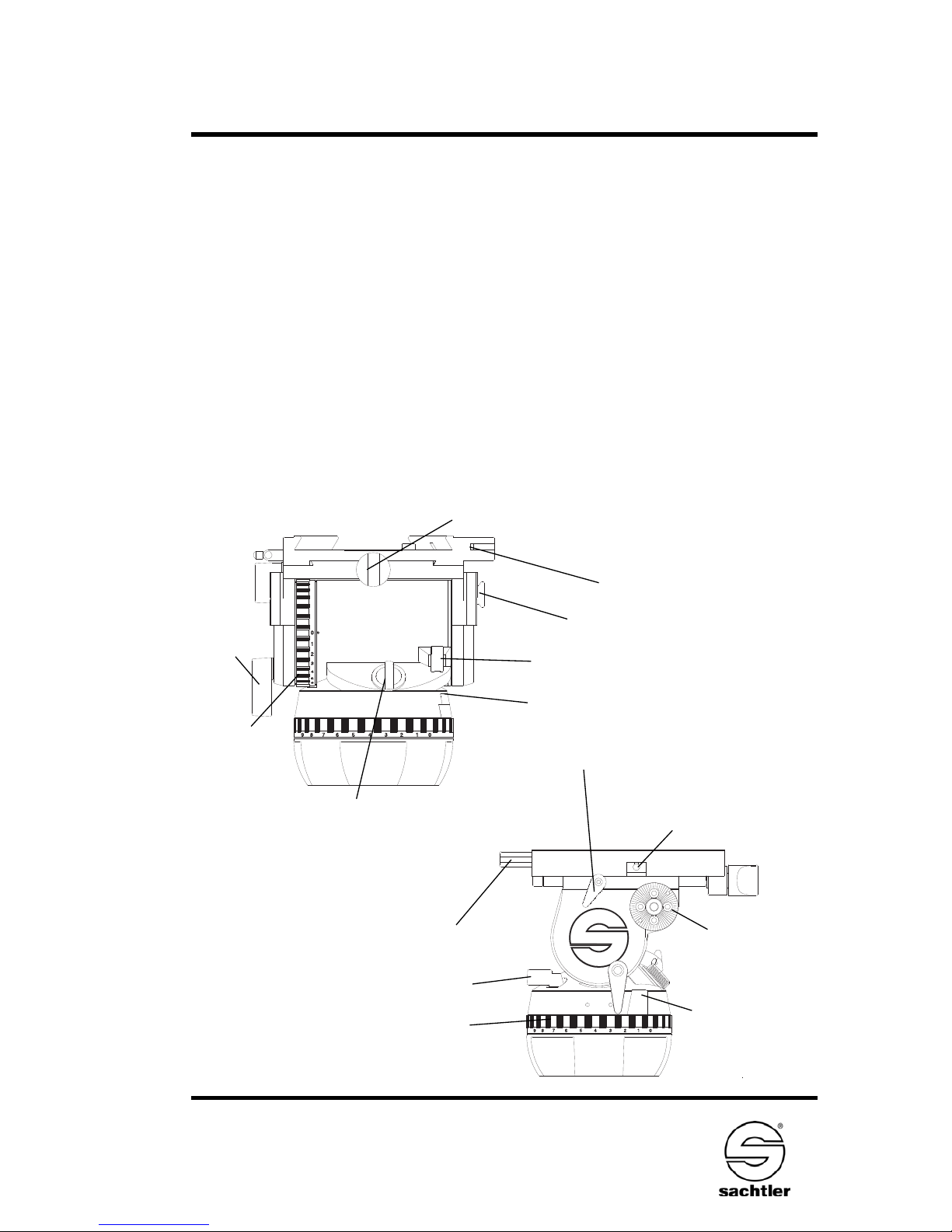
2 Operating elements
VIDEO 60
Plus
Spindle of the Camera balance plate
Safety pin of the
V-plate lock
Vertical
brake
Tilt safety lock
Horizontal brake
Vertical setting of fluid
drag
Horizontal setting of
fluid drag
Counterbalance knob
Clamp of the camera balance plate
Touch
bubble
V-plate-lock
Lever for ½ counterbalance springs
Battery holder for touch bubble
Teleprompter connection
Rosette for
mounting
panbar

ManualVideo 60 Plus Studio
- 2 -
3 Operation
3.1 Levelling of the fluid head
Touch Bubble
The Video 60 Plus Studio has a self illuminating level
bubble which allows easy levelling even under unfavourable lighting conditions.
The illumination is activated by strong tapping on the
bubble. The bubble will light up to 45 seconds.
3.2 Removing the V-plate
Push the safety pin of the V-plate lock to the front and
swing it into horizontal position. Pull the V-plate locking
lever out. The V-plate is now released and can be removed by pulling it backwards.
3.3 Mounting of the camera
Attach the camera V-plate to the tripod adapter plate
(camera accessory) around the camera’s centre of gravity.
-> Turn the counterbalance knob to position 9
-> Apply horizontal brake and release vertical brake
-> The springs of the counterbalance engage automati-
cally by tilting the camera through the horizontal
position (audible clicking).
Lock the head with the tilt safety lock.
The blocking and clicking into position of the tilt safety
lock is achieved by pulling out the red knob and turning it
90°. Green marking on the red knob becomes invisible.
Make sure that the tilt safety lock has engaged (the head
can’t be tilted any more).
-> Move camera with V-plate from the back along the
guides until it reaches the end stop.

- 3 -
Video 60 Plus StudioManual
-> Push the locking lever in and backwards until it
touches the head and secure locking of the V-plate
by lifting safety pin.
3.4 Removing of the camera
-> Lock the head with the tilt safety lock.
The blocking and clicking into position of the tilt safety lock is
achieved by pulling out the red knob and turning it 90°. Green
marking on the red knob becomes invisible. Make sure that
the tilt safety lock has engaged (the head can’t be tilted any
more).
-> Push the safety pin of the V-plate lock to the front and
swing it into horizontal position. Pull the V-plate locking
lever out. The camera with V-plate is now released and
can be removed by pulling it backwards.
Caution: If necessary the camera should be held by two
persons, as the weight can approach
65 kg / 143 lb.
3.5 Positioning of the camera
-> Hold the camera by securing the pan bar.
-> Apply horizontal brake and release vertical brake and
tilt safety lock by pulling out the red knob and turning it
90°. Green marking on the red knob becomes visible
(rocking the pan bars up and down will facilitate this).
-> Select 0 on the vertical drag adjustment ring.
-> Open the lock of camera sliding balance plate.
On the Video 60 Plus Studio the lock of camera sliding balance plate is opened on the left side of the fluid head.
-> By turning the spindle forwards and backwards move
the camera until you have reached a position where
the camera is balanced horizontally. Rear-heavy cameras are moved to the front by turning the spindle clockwise,

ManualVideo 60 Plus Studio
- 4 -
front-heavy cameras are moved to the back by turning
the spindle anti-clockwise. You will find it easier when
holding the camera in a horizontal position.
-> Secure sliding balance plate with clamping lever
(spindle drive is self-locking, clamping serves to eliminate play).
On the Video 60 Plus Studio the lock of balance plate is
closed on the left side of the fluid head.
Caution: If you can’t manage to centre the camera, you
should move the V-plate to a different position
on the tripod mounting adapter.
3.6 Adjusting the camera’s counterbalance
-> Hold the camera by securing the pan bar.
-> Turn the counterbalance knob to that number which
best compensates for the weight of the camera.
-> After each spring is released, check if the camera will
remain in a tilted position, without moving upwards or
downwards significantly.
Engaging or disengaging the lever for 1/2 springs (small weight
symbol will apply) or release half a spring which will help to
select optimum counterbalance. When spring is engaged lever
should be in an up right posi tion, metal pin is not visible - if
disengaged metal pin inside the lever is visible.
-> Please note: A lower counterbalance setting becomes
immediately effective in any tilt position. An increase of
the counterbalance setting will only be effective in the
horizontal position (springs must click in audibly).
3.6.1 Engaging and disengaging of fixed counterbalance
springs (should only be performed in special situations)
The Video 60 Plus Studio has 4 fixed counterbalance
springs which are always engaged in position "1" of the
counterbalance knob. In certain situations it may be
 Loading...