

Sachtler Video 20 S1, video 18 S1 User Manual
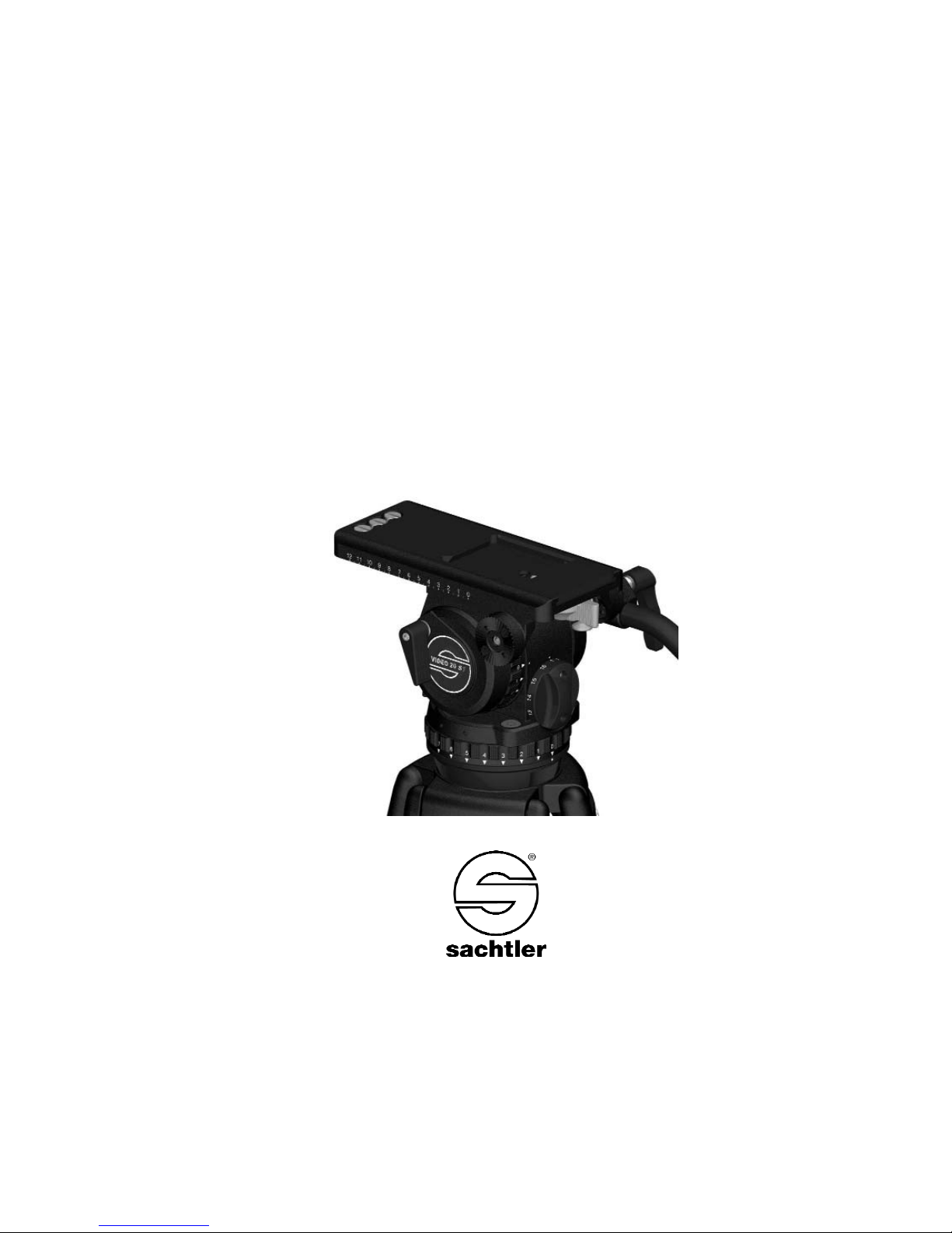
Video 20 S1
Fluid Head
Fluidkopf
Manual / Benutzerinformation

© by sachtler®. Alle Rechte vorbehalten / All rights reserved
Originalbetriebsanleitung/Original User Manual
Version: 1.6/02/12
Ausgabedatum / Issue date: 02/12
Bestellnr. / Order no.: S 2021-4980
sachtler
®
Vitec Group Videocom Division
www.vitecgroup.com
Erfurter Strasse 16 Postfach / P.O.BOX 2039
D-85386 Eching D-85380 Eching
Germany Germany
Telefon: +49/(0)89 321 58 200
Telefax: +49/(0)89 321 58 227
E-Mail: contact@sachtler.de
Internet: http://www.sachtler.com

- I -
Video 20 S1
Table of contents
1 Safety instructions / General Information.............................1
2 Operating elements..............................................................2
3 Operation..............................................................................4
3.1 Intended use ................................................................4
3.2 Moving of the pan bar ..................................................4
3.3 Levelling of the fluid head ............................................5
3.4 Mounting of the camera and / or plate.........................5
3.5 Counterbalancing of the camera..................................7
3.6 Setting of the damping.................................................8
3.7 Brakes ..........................................................................8
3.8 Change of battery ........................................................8
3.9 Transport setting of damping, counterbalance
and brakes ...................................................................9
4 Technical Data....................................................................10
5 Accessories ........................................................................11
6 Inspection & Cleaning ........................................................11
7 Warranty .............................................................................11

Inhaltsverzeichnis
1 Sicherheitshinweise / Grundlegende Hinweise..................13
2 Bedienelemente .................................................................14
3 Betrieb ................................................................................16
3.1 Bestimmungsgemäße Verwendung ...........................16
3.2 Schwenkarmverstellung .............................................16
3.3 Nivellieren des Fluidkopfes ........................................17
3.4 Entnehmen und Einsetzen der Kameraplatte ............17
3.5 Einstellen der Kamerabalance ...................................19
3.6 Einstellen der Dämpfung............................................20
3.7 Bremsen.....................................................................20
3.8 Austausch der Batterie...............................................20
3.9 Transportstellung von Dämpfung, Gewichts-
ausgleich und Bremsen .............................................21
4 Technische Daten...............................................................22
5 Zubehör ..............................................................................23
6 Inspektion & Pflege ............................................................23
7 Gewährleistung ..................................................................23
- II -
Video 20 S1

Manual
Video 20 S1
- 1 -
1 Safety instructions / General Information
Á Before using the fluid head read the manual.
Á Before mounting the fluidhead on the tripod, check if the tri-
pod has a safe standing and if the ttripod leg extensions are
clamped.
Á Before releasing the tie down on the fluid head (with a
mounted camera), the tripod must be secured against fall
over.
Á Before releasing the vertical brake (at a non balanced
camera set up) or the clamping of the camera-/balance plate
the camera must be secured against suden movement,
otherwise there may be a danger of finger trapping.
Á During camera tilt movements with extreme tilt angles there
may be a danger of finger trapping between balance plate
and housing for users and third persons.
- 2 -
Video 20 S1Manual
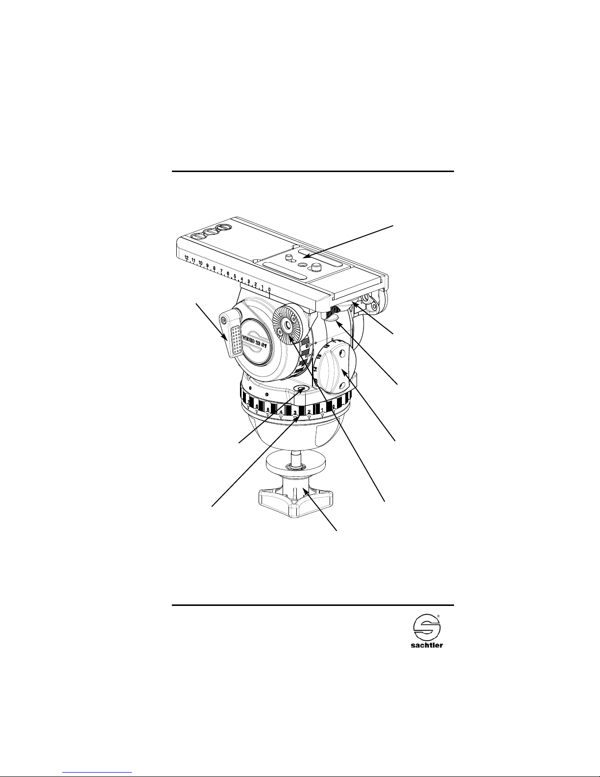
2 Operating elements
Camera plate
Safety Lock of
Touch & Go System
Counterbalance
Adjustment Knob
Vertical brake
Tie down
Pic. 1
Illuminated
Touch Bubble
Rosette for left pan bar
Horizontal drag
adjustment
Lever Locking of
Touch & Go System
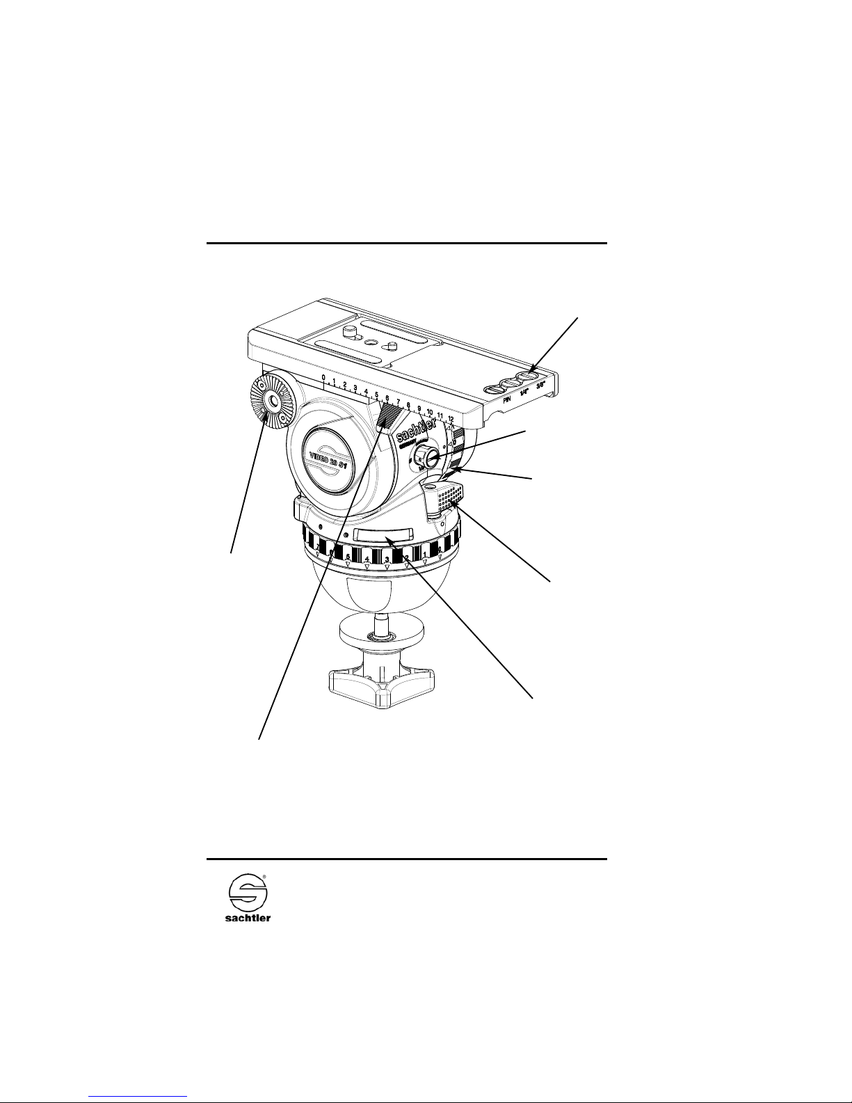
Rosette for right
pan bar
Clamp lever
balance plate
Battery compartment
for touch bubble
Payload range
shifter
Vertical drag
adjustment
Pic. 2
Manual
Video 20 S1
- 3 -
Horizontal brake
Spare/Camera
screws

- 4 -
Video 20 S1
Manual
3 Operation
3.1 Intended Use
This fluidhead was developed to enable pan- and tilt movements of cameras. The maximum payload is specified in
chapter 4.
3.2 Moving of the pan bar
Open the clamping lever of the pan bar and move the pan
bar into the desired position. Close the clamping screw of
the pan bar. While lifting the lever it will be disengaged and
can now be placed in a desired angular position.
During transportation the pan bar can be moved next to the
tripod legs.
Caution:
Open the clamping screw of the pan bar far
enough. The teeth of the pan bar clamp should not clatter
while moving the pan bar. Make sure that the teeth interleave with each other when closing the clamping lever of
the pan bar.
Use of the enclosed pan bar on the left side of the fluid
head is also possible. The pan bar has to be removed from
the head and the black plastic cap on its top should be
opened and removed with a coin or screw driver. The toothed clamp should be removed and relocated. The plastic
cap needs to be tightened again.
 Loading...