

Sachtler Video 18 S2, Video 20 S1 User Manual

Video 18 S2 & 20 S1 Fluid Heads
User Guide
Video 18 S2
Video 20 S1
Fluid Heads
Part Nos. Video 18 S2 1811
Video 20 S1 2010
EN DE
www.sachtler.com

Copyright © 2015
All rights reserved.
Original Instructions: English
All rights reserved throughout the world. No part of this publication may be stored in a retrieval system, transmitted, copied or reproduced in any
way, including, but not limited to, photocopy, photograph, magnetic or other record without the prior agreement and permission in writing of the Vitec
Group Plc.
Disclaimer
The information contained in this publication is believed to be correct at the time of printing. Vitec Videocom Ltd reserves the right to make changes
to the information or specications without obligation to notify any person of such revision or changes. Changes will be incorporated in new versions
of the publication.
We are making every effort to ensure that our publications are updated on a regular basis to reect changes to product specications and features.
Should this publication not contain information on the core functionality of your product, please let us know. You may be able to access the latest
revision of this publication from our website.
Vitec Videocom Ltd reserves the right to make changes to product design and functionality without notication.
Trademarks
All product trademarks and registered trademarks are the property of The Vitec Group Plc.
All other trademarks and registered trademarks are the property of their respective companies.
Published by:
Vitec Videocom Ltd
Email: technical.publications@vitecgroup.com

1
Contents / Inhaltsverzeichnis
Safety.....................................2
Safety and About This Guide
.................3
Box Contents
.............................. 4
Operating Elements
. . . . . . . . . . . . . . . . . . . . . . . . . 5
Installation.................................7
Touch Bubble
.............................7
Mounting the Head
........................ 7
Mounting and Dismounting the Camera
........ 8
Fitting the Pan Bar
........................10
Balancing the Payload
.....................12
Adjusting the Centre of Gravity (C of G)
.......12
Adjusting the Counterbalance
...............15
Adjusting the Drags
.......................17
Transportation
...........................18
Maintenance
.............................. 19
Technical Specication
..................... 20
General Notices
........................... 21
Sicherheit
................................ 22
Sicherheit und Über diese Bedienungsanleitung
23
Lieferumfang..............................24
Bedienelemente
........................... 25
Montage..................................27
Selbstleuchtende Libelle (Touch Bubble)
...... 27
Montage des Fluidkopfes
..................27
Einsatz und Entnahme der Kamera
..........28
Schwenkarmmontage
.....................30
Einstellen der Kamerabalance
..............32
Einstellen des Schwerpunktes (C of G)
........32
Einstellen des Gewichtsausgleichs
...........35
Einstellen der Dämpfung
...................37
Transport
...............................38
Wartung..................................39
Technische Spezikationen..................40
Allgemeine Hinweise
.......................41
2
Safety
Important information on the safe installation and operation of
this product. Read this information before operating the product.
For your personal safety, read these instructions. Do not operate
the product if you do not understand how to use it safely. Save
these instructions for future reference.
Warning Symbols Used in these Instructions
Safety cautions are included in these instructions. These safety
instructions must be followed to avoid possible personal injury and
avoid possible damage to the product.
!
WARNING!
Where there is a risk of personal injury or injury to
others, comments appear supported by the warning
triangle symbol.
Where there is a risk of damage to the product,
associated equipment, process or surroundings,
comments appear supported by the word ‘CAUTION’.
Health and Safety
!
WARNING! Risk of personal injury or injury to
others. All personnel must be fully trained and adhere
to correct manual handling techniques and Health &
Safety regulations. It is the responsibility of the local
organisation to enforce safe working practices at all
times.
!
WARNING! Do not t a head to a tripod that cannot
support the combined mass of the head and its full
payload.
Mounting and Installation
!
CAUTION! Always lock the horizontal and vertical
brakes when the camera is mounted but not in use or
when levelling the uid head on the tripod.
!
CAUTION! Hold the camera securely when mounting
or dismounting from the uid head and when making
adjustments to the tripod height or footprint.
!
CAUTION! Always hold the pan bar when making
adjustments to the counterbalance or camera
position. Do not use the pan bar to lift or move the
tripod and uid head.
!
CAUTION! Do not attach heavy items to the pan bar.
!
CAUTION! Always remove the camera before
transporting.
!
WARNING! Risk of nger entrapment. Do not place
ngers between the platform and the body of the uid
head.

3
Safety and About This Guide
The Sachtler Video 18 S2 and Video 20 S1 uid heads were
developed to enable smooth pan and tilt movement giving the
operator total image control through a wide range of angles.
This user guide has been produced to instruct the user on the correct
set-up, operation and maintenance of the uid head.
Maintenance
!
WARNING! The tting of non-approved parts and or
accessories or servicing by non-approved personnel
could effect the safety of the product. It may also
invalidate the terms and conditions of the product
warranty.
!
CAUTION! When replacing the battery, only use the
same or an equivalent type of battery recommended
for use with this product.
Intended Use
About this User Guide
Warranty
This product is covered by a one year warranty.
The warranty will be invalidated if:
• The head is improperly installed or used in a manner contrary to
this user guide.
• The head housing is opened by unauthorised personnel.
Extended Warranty
Please register at www.sachtler.com for an extended warranty period.
4
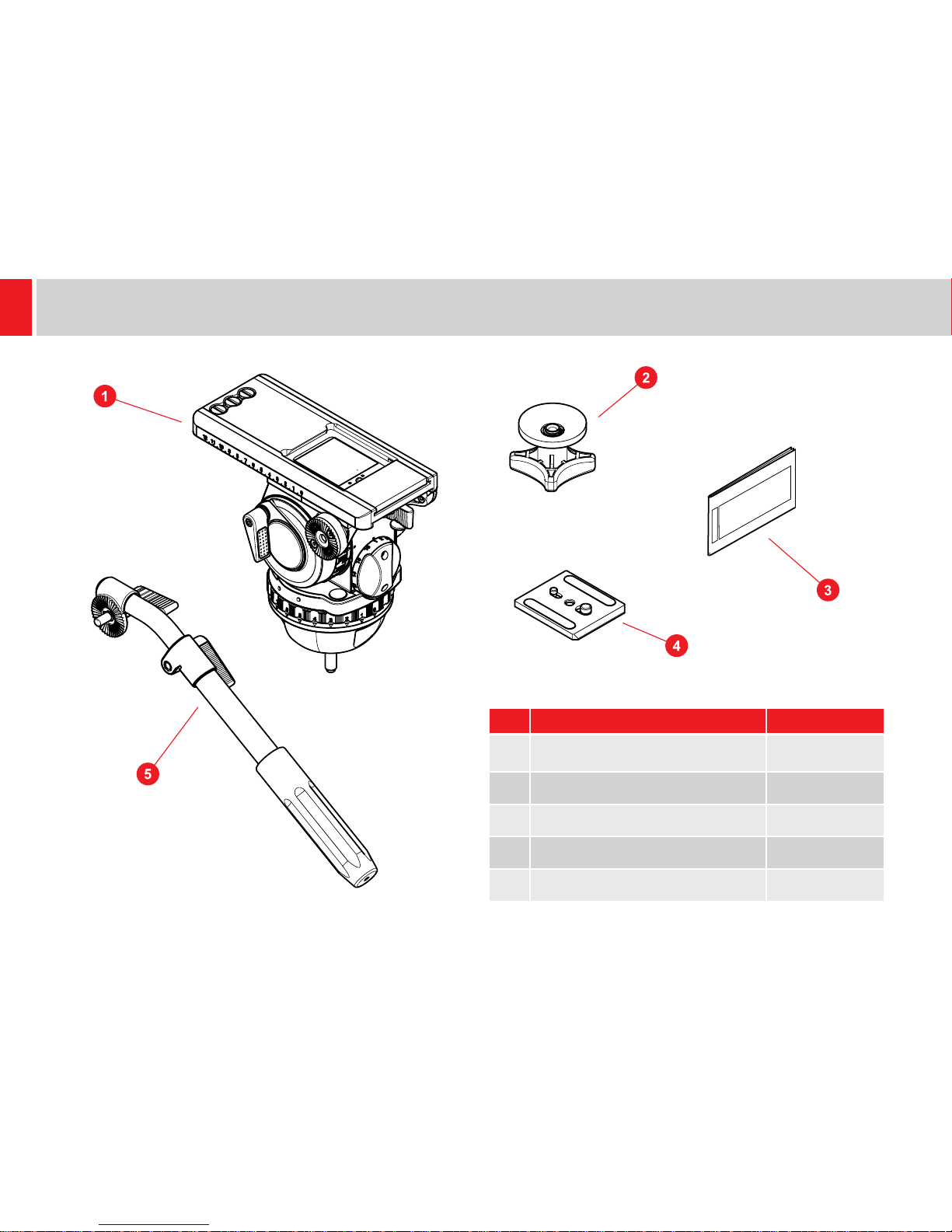
Box Contents
Item Description Part No
1 Video 18 S2 or Video 20 S1 Fluid head
1811 or
2010
2 Tie down SKO13B0366
3 User guide S2022-4980
4 Camera plate 1064
5 Pan bar plus right 3270
5
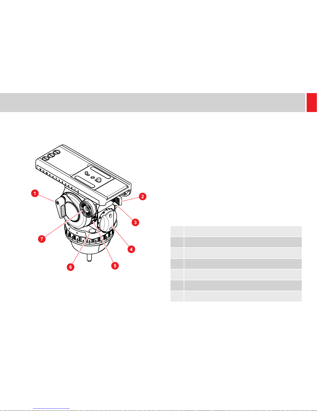
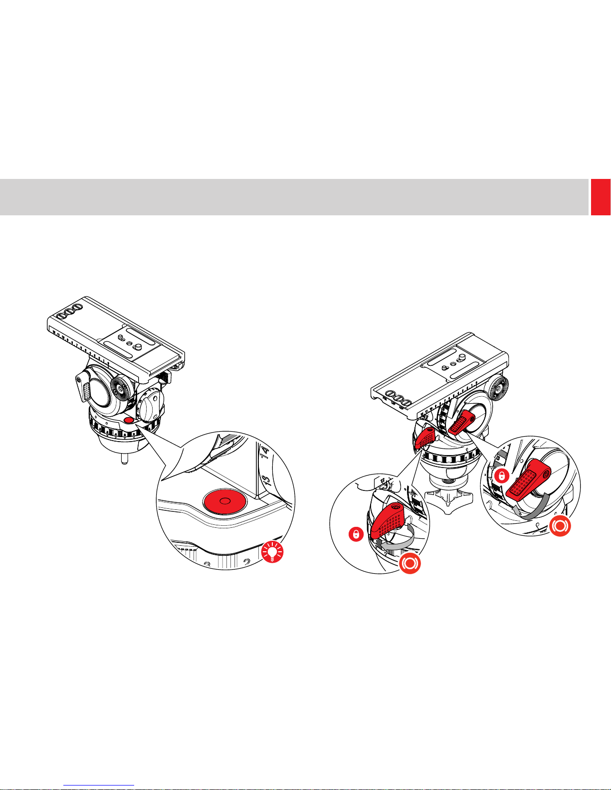
Operating Elements
1 Vertical brake
2 Touch & Go system lock lever
3 Touch & Go system safety lock
4 Counterbalance adjustment knob
5 Vertical drag control
6 Illuminated touch bubble
7 Rosette for left pan bar
Left View
6
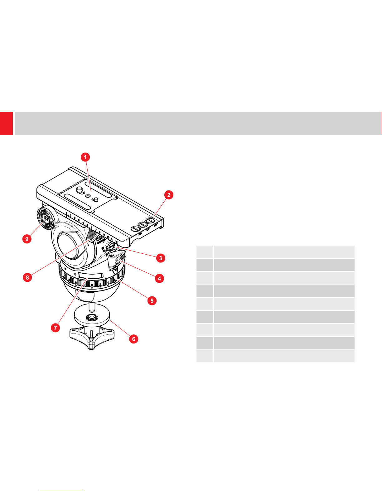
Operating Elements
1 Camera plate
2 Spare camera screws
3 Payload range shifter (boost button)
4 Horizontal brake
5 Horizontal drag control
6 Tie down
7 Battery compartment for touch bubble
8 Balance plate clamp lever
9 Rosette for right pan bar
Right View
7
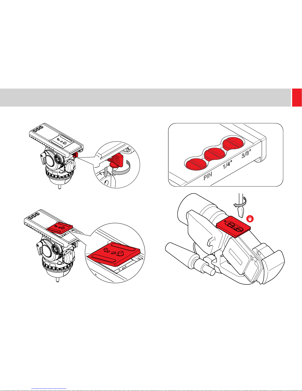
Installation
Touch Bubble
The uid head is tted with an illuminating touch bubble which
allows easy levelling in poor lighting conditions. The illumination is
activated by tapping the bubble and will automatically switch off after
approximately 20 seconds.
Levelling the Head
1. Apply the horizontal and vertical brakes and hold the head rmly
with one hand.
Mounting the Head
The uid head is designed to be installed onto standard tripods
using the tie down with the 100 mm ball base. The uid head can be
mounted to a slider or pedestal using a FB converter (# 3913).

8
Installation
2. Loosen the tie down and move the head so that the level bubble is
central. Tighten the tie down and check the level bubble remains
central when the head is rotated through a full 360º.
Mounting and Dismounting the Camera
1. Apply the horizontal and vertical brakes.
2. Hold the plate or camera with one hand. Grasp the locking lever
with your thumb and index nger and pull down the safety button.
9
Installation
3. With the safety button held down, move the locking lever as far as
possible to the left.
4. The plate or camera will be released.
5. Attach the camera plate to the camera around its centre of gravity.
Additional screws are stored in the platform assembly.
10
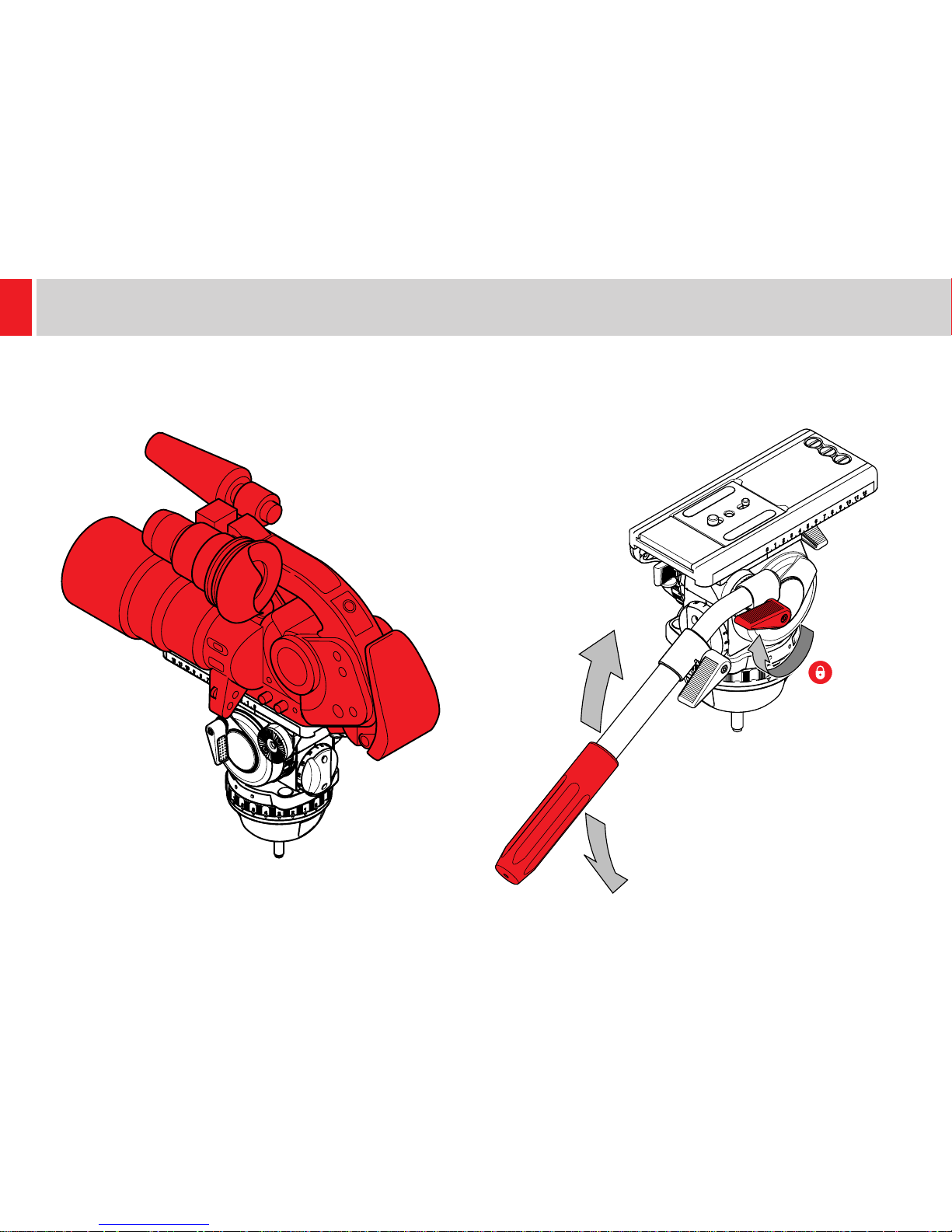
Installation
6. Mount the camera and plate onto the platform. It will lock
automatically and the lock lever will click audibly back into its initial
position.
Fitting the Pan Bar
Fit and adjust the pan bar to the desired position, tighten the clamping
screw ensuring the teeth mesh fully.
11
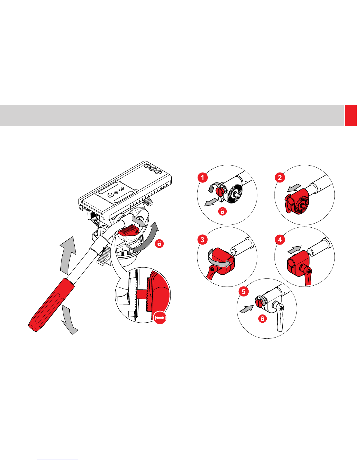
Installation
Adjusting the Pan Bar
To adjust the position of the pan bar, loosen the clamping screw
sufciently to allow the rosettes to rotate without fowling.
Conguring the Pan Bar
As standard, the pan bar is congured to mount on the right hand
side of the uid head. The pan bar can be congured for left hand
mounting, as follows:
12
Installation
Balancing the Payload
Before operating the uid head, the payload (camera, lens and any
other tted accessories) must be correctly balanced to ensure safe
and reliable operation.
!
WARNING! When balancing the payload, it is
important to be aware of the potential danger that an
unbalanced payload will fall away suddenly. Maintain
a rm hold on the payload until the balance is set
correctly.
!
WARNING! Risk of nger entrapment. Do not place
ngers between the platform and the body of the uid
head.
!
CAUTION! Always hold the pan bar when making
adjustments to the counterbalance or camera position.
!
CAUTION! The camera, pan bars and all accessories
must be tted in their operational position before
balancing the head. Any equipment tted or adjusted
later can unbalance the uid head.
Adjusting the Centre of Gravity (C of G)
Before adjusting the counterbalance, the centre of gravity (C of G) of
the payload must be centred precisely over the axis of the uid head.
Ensure that the head is level before balancing.
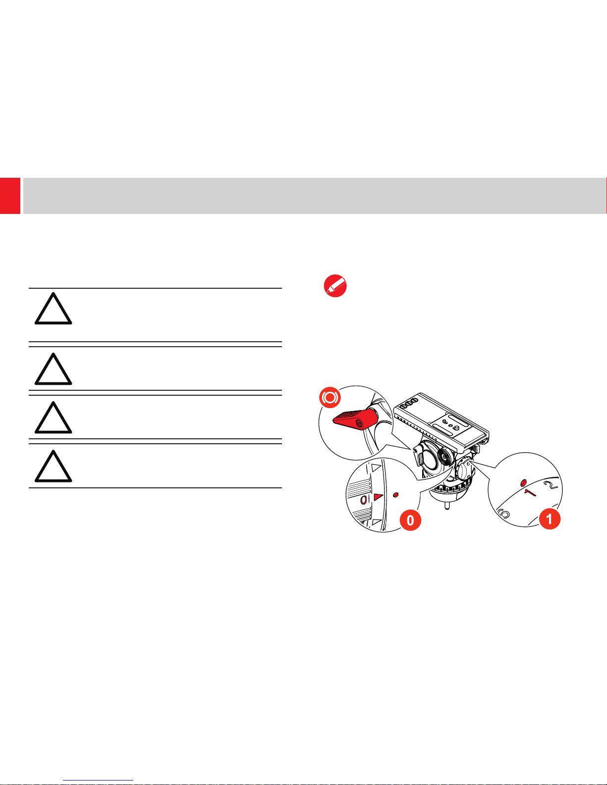
1. Apply the vertical brake and adjust the vertical setting of the uid
drag to “0”. Set the counterbalance adjustment knob to “1”. Note
moving the counterbalance from one setting to another requires the
head to pass the horizontal position to take affect.
 Loading...