

Sachtler Vario Ped 2-75 User Manual
Vario Pedestal 2-75
Manual
Benutzerinformation

© by sachtler®. Alle Rechte vorbehalten / All rights reserved
Originalbetriebsanleitung/Original User Manual
Version: 4.0/09/14
Ausgabedatum / Issue date: 09/14
Bestellnr. / Order no.: spe13t010a
sachtler
®
Vitec Group Videocom Division
www.vitecgroup.com
Erfurter Strasse 16 Postfach P.O.BOX 2039
D-85386 Eching D-85380 Eching
Germany Germany
Telefon: (+49) 89 321 58 200
Telefax: (+49) 89 321 58 227
E-Mail: contact@sachtler.de
Homepage: http://www.sachtler.com
We want you to receive
Sachtler products that are
always state of the art.
Therefore we reserve the right
to make changes based on
technical advances.
Wir wollen, dass Ihre Sachtler
Produkte immer auf dem
aktuellsten Stand sind.
Deswegen behalten wir uns
technische Änderungen vor.

- I -
Table of Contents
Table of contents
1 Safety instructions ...............................................................1
2 Characteristics .....................................................................1
3 Operation .............................................................................2
3.1 Pedestal set up ............................................................2
3.1.1 Dolly ..................................................................2
3.1.2 Column .............................................................3
3.1.3 Steering wheel ..................................................4
3.2 Camera setup and column pressurizing procedure ....4
3.3 Description of dolly functions ......................................6
3.3.1 Wheel brake......................................................6
3.3.2 Switching from crab to steer ............................6
3.3.3 Wheels and cable guards.................................6
3.4 Description of the column functions............................7
3.4.1 Quickfix.............................................................7
3.4.2 Column brake ...................................................7
3.4.3 Drag ..................................................................8
3.5 Trim weights.................................................................8
4. Troubleshooting ...................................................................9
5 Technical specifications.......................................................9
5.1 Dimensions ................................................................10
6 Warranty.............................................................................10

Inhaltsverzeichnis
- II -
Inhaltsverzeichnis
1 Sicherheitshinweise............................................................11
2 Eigenschaften.....................................................................11
3 Betrieb................................................................................12
3.1 Aufbau des Pedestals ................................................12
3.1.1 Dolly ................................................................12
3.1.2 Säule ...............................................................13
3.1.3 Handrad ..........................................................13
3.2 Montage der Kameraausrüstung und
Befüllen der Säule......................................................14
3.3 Funktionsbeschreibung des Dollys............................16
3.3.1 Radbremse .....................................................16
3.3.2 Umschaltung von 1- auf 3-Radbetrieb...........16
3.3.3 Doppelrollen und Kabelschutz .......................17
3.4 Funktionsbeschreibung der Säule .............................18
3.4.1 Quickfix...........................................................18
3.4.2 Feststellbremse für Säule ...............................18
3.4.3 Drag ................................................................19
3.5 Trimmgewichte...........................................................19
4 Fehlersuche........................................................................20
5 Technische Daten ..............................................................21
5.1 Abmessungen ............................................................21
6 Gewährleistung ..................................................................22
- 1 -
Vario Pedestal 2-75
Manual
1 Safety instructions
-> Pneumatic column is under pressure of up to 12 bars
(174 psi)
-> If one of the column lids has been damaged there is a possibility of getting injured. Therefore only use the column
again after its repair by a service technician.
-> Don’t use the column before it isn’t correctly locked into the
dolly.
-> Never release the transport lock without a payload in place,
since the unloaded column will move up strongly. This may
cause injuries or damage.
-> Never push down column with “LOCK” or “DRAG” applied.
2 Characteristics
The Vario Ped 2-75 is a “true” two stage pedestals for OB
and studio applications. They have an extended “on-air”
stroke of 77cm/30 inches.
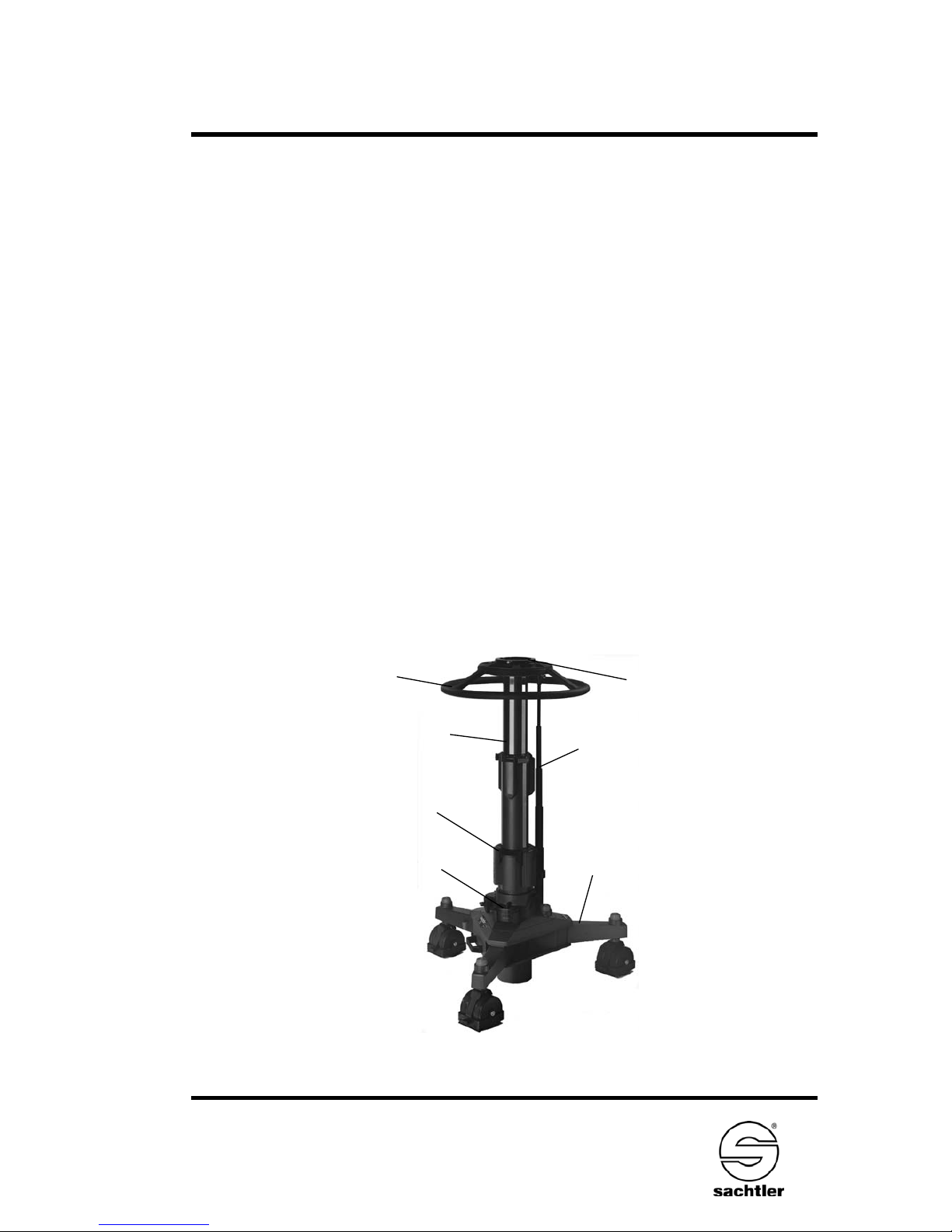
Fig. 1
Steering wheel
Dolly
Cardan
Column
Quickfix
Trim weight
Cover lid
Manual
Vario Pedestal 2-75
- 2 -
3 Operation
Please follow the following steps in order while setting up the
Pedestal:
-> Lock column into the dolly.
-> Mount all payload completely.
-> Release transport lock.
-> Pressurize column until it moves upward by itself.
-> Proceed with fine adjustment on the pedestal’s valve.
3.1 Pedestal Set Up
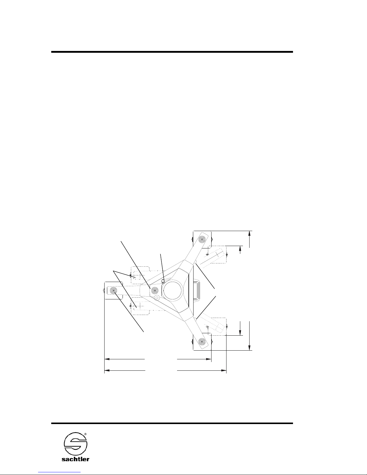
3.1.1 Dolly
Fig. 2
840 mm
956 mm
690 mm (Narrow track)
921 mm (Standard track)
Transport position
Red Slider
Lever of lock
collar
Switching from
crab to steer
Wheel brake (3-times)
- 3 -
Vario Pedestal 2-75
Manual
Press down red slider at the side of the dolly and swing
out the swivel arm at the same time. Release the slider
after disengaging. Make sure that swivel arm locks again
automatically in the desired position and slider moves up.
1. locking position = standard track 92 cm (36.2 in.)
2. locking position = narrow track 69 cm (27.2 in.)
Changing track is not possible when using the Studio
dolly. Lock at least one pair of wheels with the wheel
brake.
Check whether the lock collar on the guide tube of the
dolly is opened sufficiently to receive the column.
3.1.2 Column
The contracted column with the transport lock engaged
can be carried on the exterior steering rod.
Place the column fully vertical and in the right position
into the guide tube (watch position of the side cardan).
When the locating pin engages and the column is in its
lowest position, the lock collar must be tightened.
Do not overtighten the lock collar!
Fig. 3
Cardan
Centering pin

Manual
Vario Pedestal 2-75
- 4 -
By turning the steering wheel a full 180°, the
steering column automatically engages into the
steering mechanism of the dolly.
3.1.3 Steering wheel
The steering wheel is attached to the upper gear
box with three screws. To lock it use the enclosed
4 mm hexagonal key, which is located at the side of
the dolly.
Movable red clips, which serve as indicators for the
running direction, are located on the steering wheel.
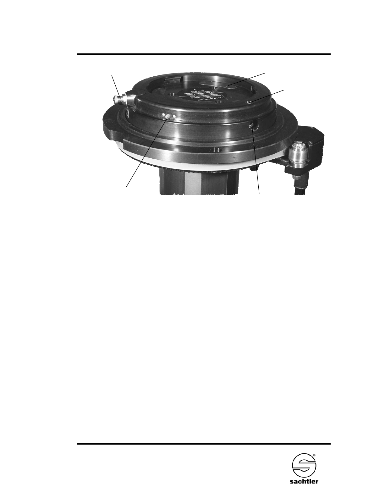
3.2. Camera setup and column pressurizing procedure
Turn the steering wheel so that the recess for Quickfix
operation is accessible (the two red arrows meet).
A 6 mm hexagonal key is located next to the dolly’s transport boxes for trim weights opens the Quickfix camera
head lock. When opened, the red indicator pins move out.
Fit the pan and tilt head, close the Quickfix (the red indicator pins move in).
Caution: The Quickfix lock will accept all Sachtler flat
base heads directly or via adapter. Check for
compatibility before attempting to fit another
manufacturer’s head.
Only after the complete camera equipment
payload is mounted on the column (max. 75kg
/ 165lbs) the transport lock can be opened by
depressing the column and disengaging the
locking lever.
Caution: Should the transport lock be released without
a load, the column will rise quickly (and
possibly dangerously) by itself.
- 5 -
Vario Pedestal 2-75
Manual
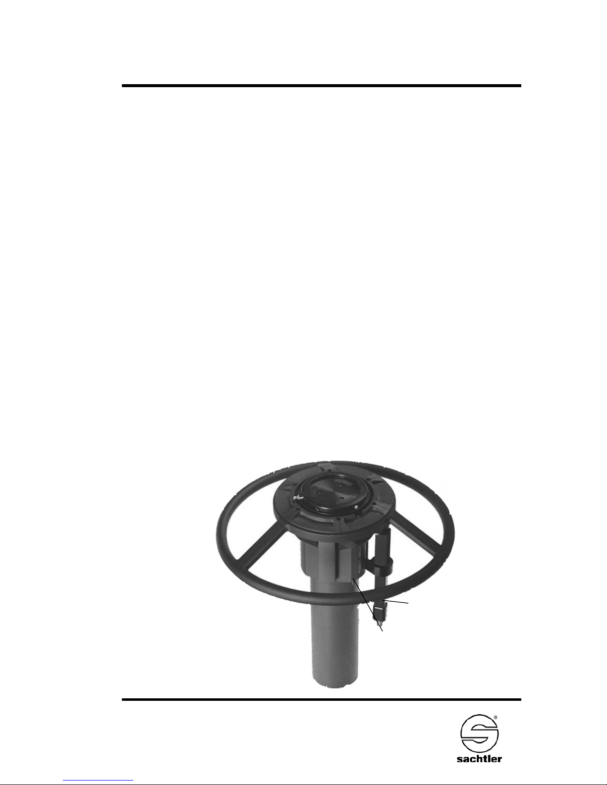
Quickfix
connection valve
Arrow mark
Clampscrew of
Quickfix
Signal pin
Fig. 4
The column should be filled with air. This is done with the
enclosed pump or a compressor (max. 12 bar/ 174 psi) in
depressed column position). A safety valve is installed in the
system to prevent overpressurizing the column.
In general the column is filled with a minimum pressure of
2 bar (29 psi) in order to secure a permanent tension on
the installed cables. This equals a necessary payload of
10 kg/22 lbs.
Connect pump/compressor; the connecting valve is located at the side of the Quickfix.
In order to compensate for any change in temperature
during a broadcast, three trim weights should be placed
on the column.
The column may now be pressurized with air until it moves
up by itself.
Disconnect the hose from the column and press the center
pin of the valve to perform a fine adjustment for a precise
weight compensation.
 Loading...