

Sachtler Studio 9+9 User Manual
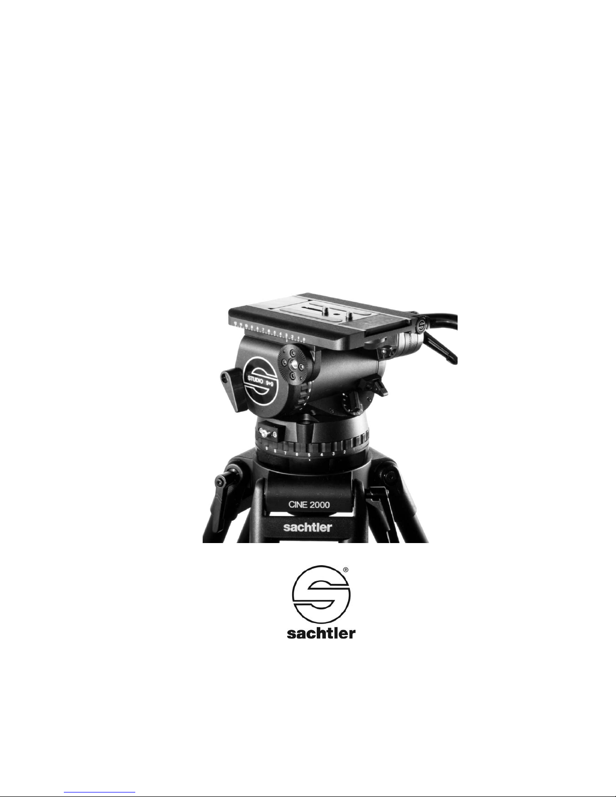
Studio 9+9
Manual
Benutzerinformation
Fluid Head
Fluidkopf

© by sachtler®Alle Rechte vorbehalten / All rights reserved
Version: 2.9/02/12
Ausgabedatum / Issue date: 02/12
Bestellnr. / Order no.: sko16t090a
Originalbetriebsanleitung/Original User Manual
sachtler
®
Vitec Group Videocom Division
www.vitecgroup.com
Erfurter Strasse 16 Postfach / P.O.BOX 2039
D-85386 Eching D-85380 Eching
Germany Germany
Telefon: (+49) 89 32 15 82 00
Telefax: (+49) 89 32 15 82 27
E-Mail: contact@sachtler.de
Homepage: http://www.sachtler.com
We want you to receive
Sachtler products that are
always state of the art.
Therefore we reserve the right
to make changes based on
technical advances.
Wir wollen, dass Ihre Sachtler
Produkte immer auf dem aktuellsten Stand sind.
Deswegen behalten wir uns technische Änderungen vor.

- I -
Table of contents
1 Safety instructions ...............................................................1
2 Operating elements..............................................................1
3 Operation .............................................................................2
3.1 Levelling of the fluid head............................................2
3.2 Removing of the camera plate ...................................2
3.3 Mounting of the camera...............................................2
3.4 Removing of the camera..............................................3
3.5 Positioning of the camera ............................................4
3.6 Adjusting the camera’s counterbalance ......................4
3.6.1 Engaging and disengaging of fixed
counterbalance springs.......................................5
3.6.2 Please note: ........................................................6
3.7 Setting of the Damping................................................7
3.8 Brakes ..........................................................................7
3.9 Support for view finder extension and Front Box .......8
3.10 Change of the batteries ...............................................8
3.11 Transport setting of damping, counterbalance and
brakes ..........................................................................8
4. Technical specifications.......................................................8
4.1 General data ................................................................8
4.2 Dimensions ..................................................................9
5 Conversion of the Studio 9+9 to include Mitchell base ....10
6 Accessories........................................................................10
7 Warranty.............................................................................10

Inhaltsverzeichnis
- II -
1 Sicherheitshinweise............................................................11
2 Bedienelemente .................................................................11
3 Betrieb................................................................................12
3.1 Nivellieren des Fluidkopfes ........................................12
3.2 Entnehmen der Kameraplatte ...................................12
3.3 Einsetzen der Kamera ...............................................12
3.4 Entnehmen der Kamera .............................................13
3.5 Zentrieren des Kameragewichts ................................14
3.6 Einstellen der Kamerabalance ..................................14
3.6.1 Ab- bzw. Zuschalten der festeingestellten
Ausgleichsfedern...............................................15
3.6.2 Bitte beachten Sie: ...........................................16
3.7 Einstellen der Dämpfung............................................17
3.8 Bremsen.....................................................................17
3.9 Sucherlupenstütze und Front Box .............................18
3.10 Austausch der Batterien ............................................18
3.11 Transportstellung von Dämpfung, Gewichts-
ausgleich und Bremsen .............................................18
4 Technische Daten ..............................................................18
4.1 Allgemeine Daten .......................................................18
4.2 Abmessungen ............................................................19
5 Umbau des Studio 9+9 auf Mitchell Basis ........................20
6 Zubehör..............................................................................20
7 Gewährleistung ..................................................................21
- III -

- IV -

- 1 -
Studio 9+9Manual
1 Safety instructions
Á
When the camera is mounted, the clamping screw of the Studio
9+9 must only be released if camera and tripod are secured
against falling over.
Á When placing the camera plate into the Studio 9+9, make sure not
to hold fingers within the range of the locking lever, since it will
snap back.
Á When releasing the vertical brake make sure that the camera is
secured against any sudden movement.
Á Do not operate the fluid head upside down without the necessary
securing devices, i.e. ropes etc.
Á Before transport reset fluid damping to “0”.
2 Operating elements
Safety lock of Touch
& Go System
Vertical brake
Horizontal brake
Vertical setting
of fluid damping
Horizontal setting of
fluid damping
Counterbalance knob
Touch bubble
Flange for viewfinder Extension
Locking lever of
Touch & Go System
Lever for ½ counterbalance spring
Clamp of sliding
Balanceplate
Clamp screw
of fluid head
Battery holder
for Touch bubble
Rosette for
mounting pan bar
Spindle of Camera-Slidingplate
tilt safety lock

ManualStudio 9+9
- 2 -
3 Operation
3.1 Levelling of the fluid head
The Studio 9+9 has a bubble to facilitate levelling.
Apply the vertical brake of the Studio 9+9 and hold the
camera with one hand. Open the clamping screw of the
fluid head and move the head in such a way, that the bubble moves into the levels black circle. Tighten the clamping screw firmly.
Touch Bubble
The Studio 9+9 has a self illuminating spirit bubble which
allows easy levelling even under unfavourable lighting
conditions.
The illumination is activated by strong tapping on the bubble. Depending on the force applied the bubble will glow
up to 45 seconds.
3.2 Removing of the camera plate
The Studio 9+9 comes with a Touch & Go quick release
plate.
Á Hold the camera plate with one hand.
Á Grasp the locking lever with your thumb and index and
pull down the red safety button.
Á Move the locking lever as far as possible to the left
(audible clicking) and take out the camera plate.
3.3 Mounting of the camera
Attach the camera plate to the tripod adapter plate (camera accessory) around the camera’s centre of gravity.
Á Turn the counterbalance knob to position 9
Á Apply horizontal brake and release vertical brake.

- 3 -
Studio 9+9Manual
Á The springs of the counterbalance engage automati-
cally by tilting the camera through the horizontal position (audible clicking).
Á Lock the head with the tilt safety lock.
The blocking and clicking into position of the tilt safety
lock is achieved by pulling out the red knob and turning it
90°. Green marking on the red knob becomes invisible.
Make sure that the tilt safety lock has engaged (The head
can’t be tilted any more).
Á Put the front of the camera plate in place first.
Á By fitting the camera onto the head it will lock automa-
tically and the locking lever will snap back audibly into
its initial position.
3.4 Removing of the camera
Á Lock the head with the tilt safety lock.
The blocking and clicking into position of the tilt safety
lock is achieved by pulling out the red knob and turning it
90°. Green marking on the red knob becomes invisible.
Make sure that the tilt safety lock has engaged (The head
can’t be tilted any more).
Á Hold the camera with one hand.
Á Grasp the locking lever with your thumb and index and
pull down the red safety button.
Á Move the locking lever as far as possible to the left
and take out the camera plate.
 Loading...