

Sachtler Ace Matte Box User Manual
Ace Matte Box
Manual

Copyright © 2013
All rights reserved.
Publication number: S2152-4980/1
Original instructions: English.
All rights reserved throughout the world. No part of this
document may be stored in a retrieval system, transmitted,
copied or reproduced in any way, including, but not limited
to, photocopy, photograph, magnetic or other record
without the prior agreement and permission in writing of
the Vitec Group plc.
We want you to receive Sachtler products that are always
state of the art. Therefore we reserve the right to make
changes based on technical advances.
Disclaimer
The information contained in this manual is believed to be
correct at the time of printing. Vitec Videocom Ltd reserves
the right to make changes to the information or
specifications without obligation to notify any person of
such revision or changes. Changes will be incorporated in
new versions of the publication.
We are making every effort to ensure that our manuals are
updated on a regular basis to reflect changes to product
specifications and features. Should this manual not contain
information on the core functionality of your product,
please let us know. You may be able to access the latest
revision of this manual from our website.
Vitec Videocom Ltd reserves the right to make changes to
product design and functionality without notification.
Published by:
Vitec Videocom Ltd
Supports Technical Publications Department
William Vinten Building
Western Way
Bury St Edmunds
Suffolk IP33 3TB
United Kingdom
E-mail: technical.publications@vitecgroup.com

Ace Matte Box
Manual
English . . . . . . . . . . . . . . . . . . . . . Page 1
Deutsch. . . . . . . . . . . . . . . . . . . . Seite 15
Español . . . . . . . . . . . . . . . . . . .Página 29
Français . . . . . . . . . . . . . . . . . . . Page 43
Português . . . . . . . . . . . . . . . . .Página 57
中文 . . . . . . . . . . . . . . . . . . . . . . . 页码 71


EN
EN
Table of contents
Page
Safety instructions . . . . . . . . . . . . . . . . . . . . . . . . . . . . . . . . . . . . . . . . . . . . . . . . . 2
Usage. . . . . . . . . . . . . . . . . . . . . . . . . . . . . . . . . . . . . . . . . . . . . . . . . . . . . . . . . . . .2
Warranty . . . . . . . . . . . . . . . . . . . . . . . . . . . . . . . . . . . . . . . . . . . . . . . . . . . . . . . . . 2
Technical specification . . . . . . . . . . . . . . . . . . . . . . . . . . . . . . . . . . . . . . . . . . . . .3
Operating elements . . . . . . . . . . . . . . . . . . . . . . . . . . . . . . . . . . . . . . . . . . . . . . . . 4
Assembly . . . . . . . . . . . . . . . . . . . . . . . . . . . . . . . . . . . . . . . . . . . . . . . . . . . . . . . . 6
Assembling the flags . . . . . . . . . . . . . . . . . . . . . . . . . . . . . . . . . . . . . . . . . . . . . . . . . . . . . 6
Assembling the filter frames. . . . . . . . . . . . . . . . . . . . . . . . . . . . . . . . . . . . . . . . . . . . . . . . 8
Assembling the rod bridge . . . . . . . . . . . . . . . . . . . . . . . . . . . . . . . . . . . . . . . . . . . . . . . . . 9
Operation . . . . . . . . . . . . . . . . . . . . . . . . . . . . . . . . . . . . . . . . . . . . . . . . . . . . . . . 10
Mounting the Ace Matte Box . . . . . . . . . . . . . . . . . . . . . . . . . . . . . . . . . . . . . . . . . . . . . . 10
Removing the Ace Matte Box . . . . . . . . . . . . . . . . . . . . . . . . . . . . . . . . . . . . . . . . . . . . . 11
Maintenance . . . . . . . . . . . . . . . . . . . . . . . . . . . . . . . . . . . . . . . . . . . . . . . . . . . . . 13
Cleaning. . . . . . . . . . . . . . . . . . . . . . . . . . . . . . . . . . . . . . . . . . . . . . . . . . . . . . . . . . . . . . 13
-1-
EN
EN
Safety instructions
Read the General Safety and
Operating instructions before using
the product.
Always press the filter release buttons
to insert or remove the filter frames.
Failure to do so may cause damage to
the Ace Matte Box.
Clean regularly using a soft cloth and
mild detergent.
Dry the product after use in wet
conditions.
Should the product become defective,
contact your local Sachtler service
center. To find your local service
center visit www.sachtler.com
Usage
The Ace Matte Box is designed for use by
professional camera operators to block
sunlight in order to prevent glare and lens
flare. The Ace Matte Box must be mounted
onto a suitable base plate, head and tripod,
designed to support the total payload.
Scan Quick Reference (QR)
code to view the Sachtler
website.
Warranty
The warranty expires if:
(a) The Ace Matte Box was operated
improperly or not in line with the specified
technical data.
(b) The Ace Matte Box housing was opened
by unauthorized personnel.
Sachtler reserve the right to make changes to product design and performance as technology advances.
Please register your product for an extended warranty period at www.sachtler.com
-2-
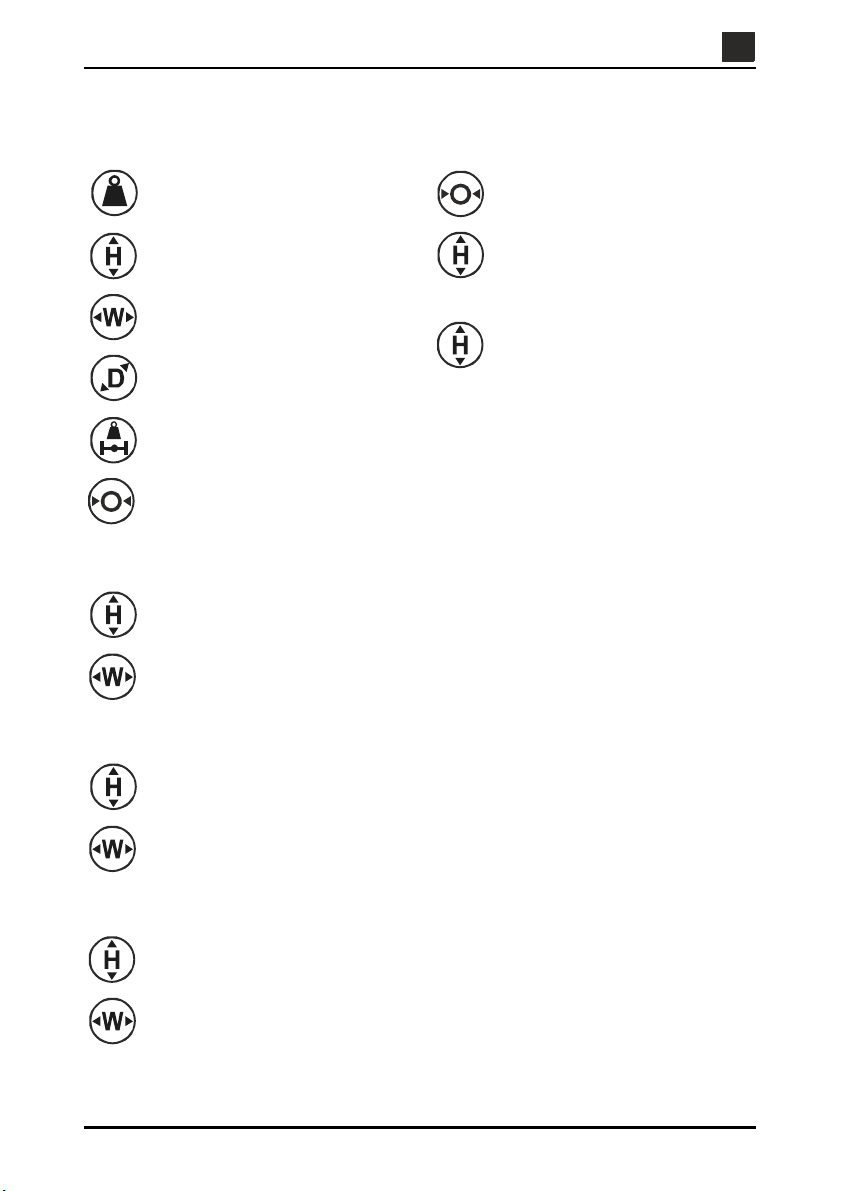
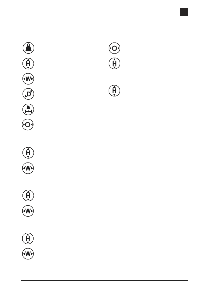
Technical specification
EN
EN
Ace Matte Box
0.88 kg (1.9 lb) (Incl. top flag, side
flags and rod bridge)
21 cm (8.2 in.)
27.8 cm (10.9 in.) (Incl. top flag)
28.5 cm (11.2 in.)
43 cm (16.9 in.) (Incl. side flags)
7.9 cm (3.1 in.)
12.3 cm (4.8 in.) (Incl. flags)
1 kg (2.2 lb)
(each side)
Ø14 cm (5.5 in.)
(Max lens diameter)
Top flag
32.7 cm (12.8 in.)
14.7 cm (5.7 in.)
Rod bridge
Ø15 mm (0.5 in.) (Support rod
diameter)
8.5 cm (3.3 in.) (Small diameter
camera lens configuration - centre
of support rod to centre of rear
clamping interface)
10.9 cm (4.3 in.) (Large diameter
camera lens configuration - centre
of support rod to centre of rear
clamping interface)
Side flags
18.8 cm (7.4 in.)
12.7 cm (5 in.)
Filter frames
10 cm (4 in.) (Square filters)
10 cm (4 in.) (Rectangular filters)
10 cm (4 in.) (Square filters)
14 cm (5.65 in.) (Rectangular
filters)
-3-
EN
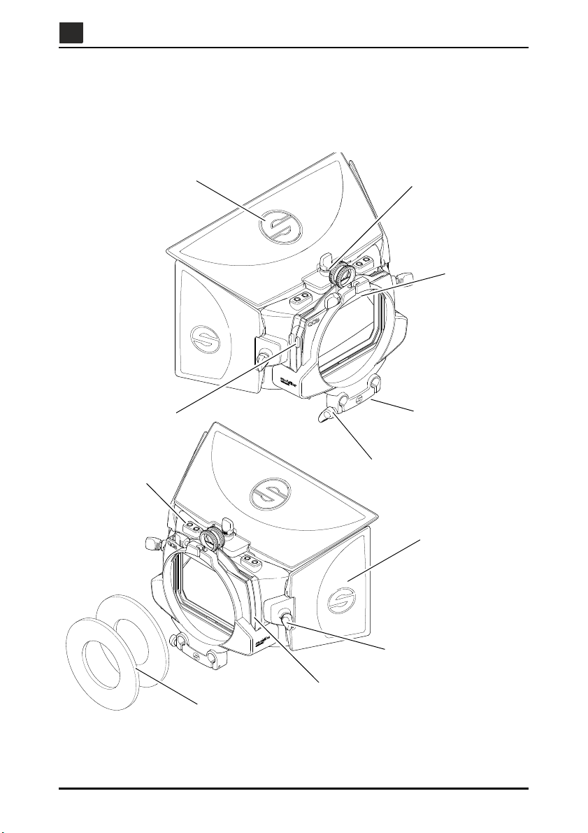
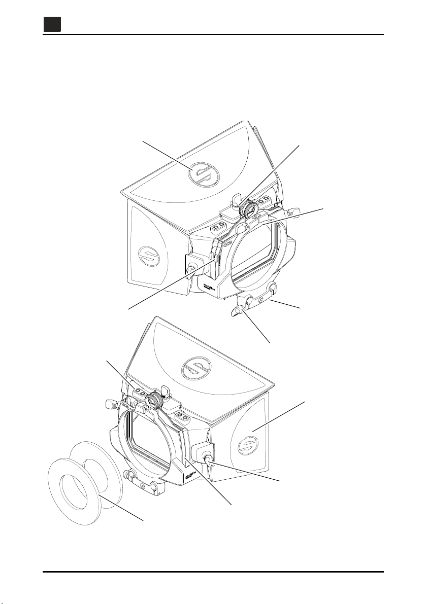
Top flag
Top flag clamp
Accessory bar
Filter frames
Side flag
Side flag clamp
Filter frame
Rear clamping
Rod bridge
Support rod clamp
interface
release button
Neoprene rings
EN
Operating elements
The Ace Matte Box has been designed to support a range of DSLR and HDV cameras. The Ace
Matte Box embodies adjustable top and side flags and attachment points, two accessory bars,
two filter stages, rear clamping interface and a rod bridge.
Fig. 1 Operating elements
-4-

EN
EN
Top and side flags / clamps
The Ace Matte Box allows top and side flags to be installed and adjusted as required. The top
flag clamp is located on top of the sunshade, between the two accessory bars. The side flag
clamps are located on the left-hand and right-hand side of the sunshade.
Accessory bars
Two accessory bars allow a variety of products, such as lights or microphones to be attached to
the sunshade. Each accessory bar comprises two 1/4” 20 UNC threaded inserts. The accessory
bars are located on top of the sunshade, one each side of the top flag clamp.
Filter stages
Two filter stages, one fixed and one that rotates, accommodate two filter frames. The filter
stages are located between the sunshade and rear clamping interface.
Filter frames
Two filter frames accommodate two different sized filters (4” x 4” and 4” x 5.65”). The filter stages
are located between the sunshade and rear clamping interface.
Filter frame release buttons
Two filter frame release buttons, one for the front filter stage and one for the rear filter stage,
when pressed, allow the filter frames to be inserted or removed from the filter stage housing. The
filter frame release buttons are located on the left-hand side of the filter stages (operators view
looking forward).
Rear clamping interface
The rear clamping interface allows a reduction ring to be fitted, to accommodate a range of lens
diameters.
Rod bridge
The rod bridge allows the Ace Matte Box to be mounted to the Ace Base Plate. The rod bridge
can be installed in two positions, depending on the lens diameter used.
Ace Matte Box mounting
The Ace Matte Box is mounted directly onto the support rods that are installed on the Ace Base
Plate. The rod bridge, that is attached to the Ace Matte Box is pushed onto the support rods until
the camera lens is seated inside the recess of the rear clamping interface.
Accessories
To provide further shade from the sunlight, the Ace Matte Box is supplied with two neoprene
rings that flex over the camera lens. When the camera is in position, the neoprene ring can be
moved along the lens to meet with the rear clamping interface.
The Ace Matte Box is also supplied with a 3 mm Allen key, to enable assembly and disassembly
of the rod bridge.
-5-
EN
EN
Assembly
Assembling the flags
The Ace Matte Box comes with two side flags and one top flag. The side flags are secured by
clamps, located either side of the sunshade. The top flag is secured by a clamp on top of the
sunshade, between the two utility bars.
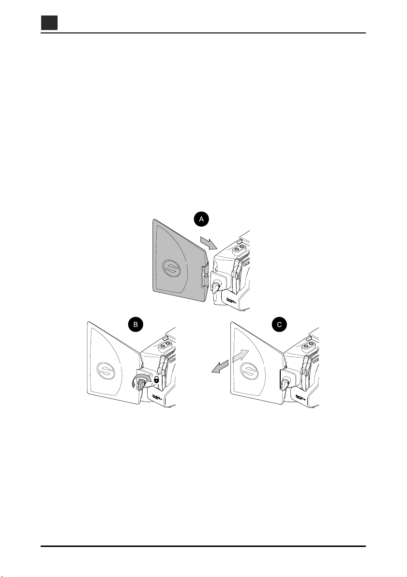
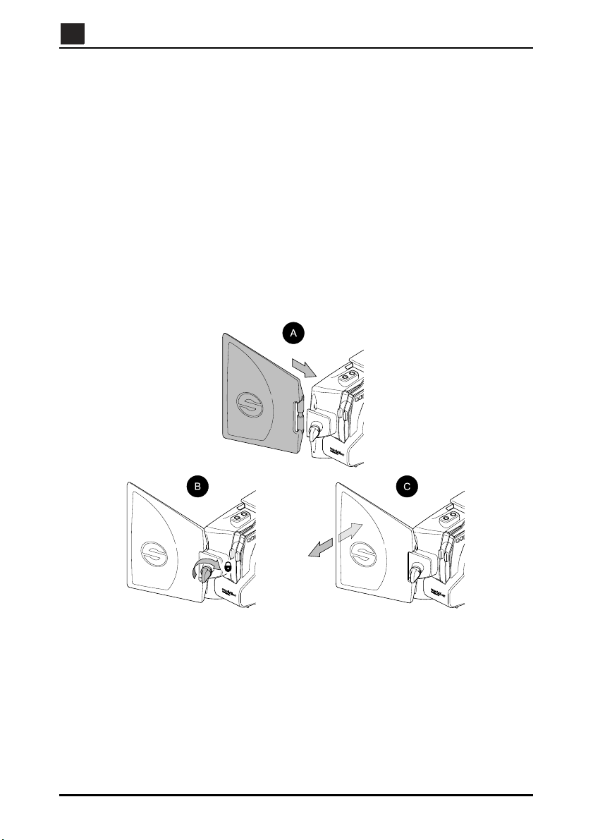
To assemble the side flags onto the Ace Matte Box (see Fig. 2):
If required, turn the side flag clamp knob counter-clockwise to loosen the side flag
clamp.
Insert the side flag cut-out between the sunshade and the side flag clamp [A], then
tighten the side clamp knob [B] until it grips the side flag.
Adjust the angle of the side flag as desired [C], then tighten the side clamp knob [B].
Fig. 2 Assembling the side flags
-6-
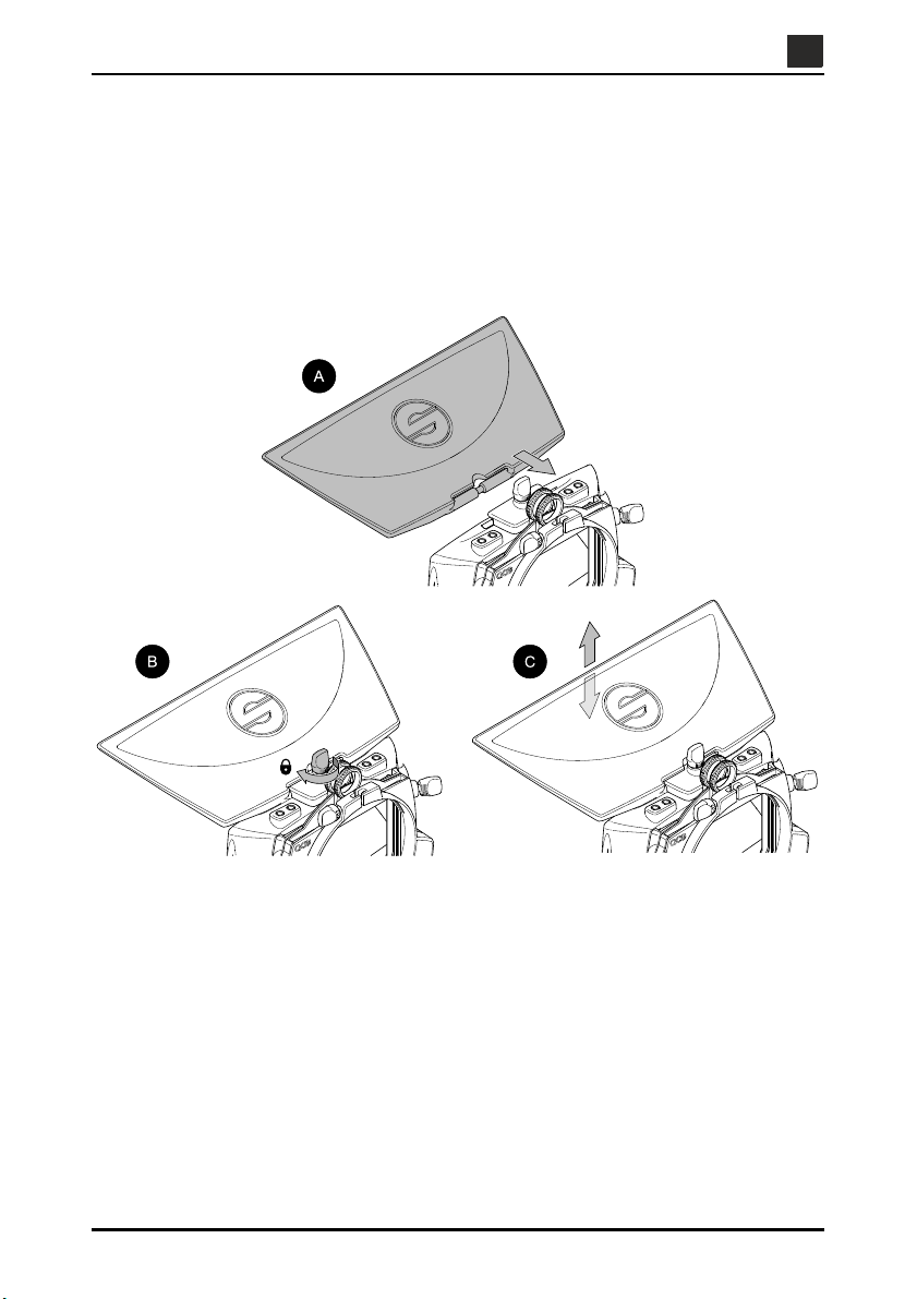
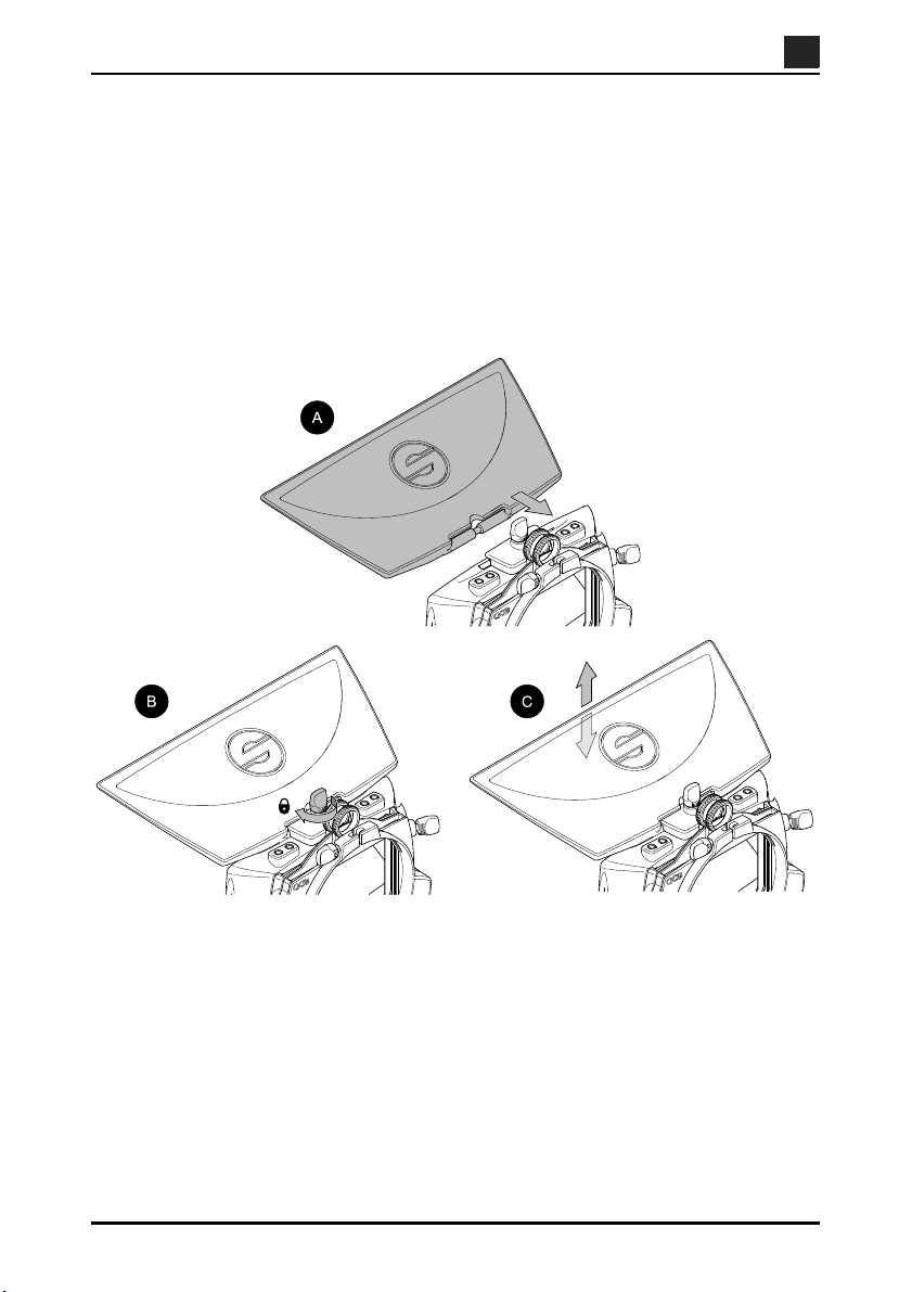
To assemble the top flag onto the Ace Matte Box (see Fig. 3):
If required, turn the top flag clamp knob counter-clockwise to loosen the top flag clamp.
Insert the top flag cut-out between the sunshade and the top flag clamp [A], then tighten
the top clamp knob [B] until it grips the top flag.
Adjust the angle of the top flag as desired [C], then tighten the top clamp knob [B].
EN
EN
Fig. 3 Assembling the top flag
-7-
EN
!
EN
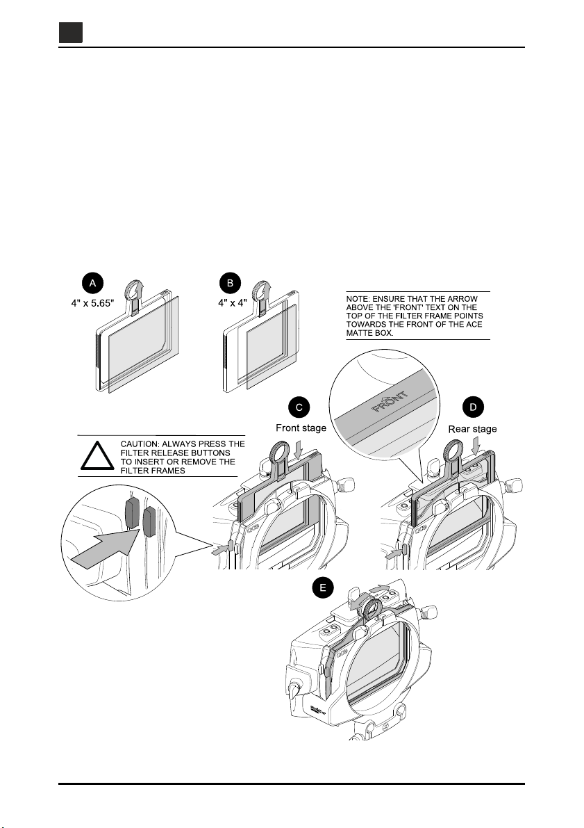
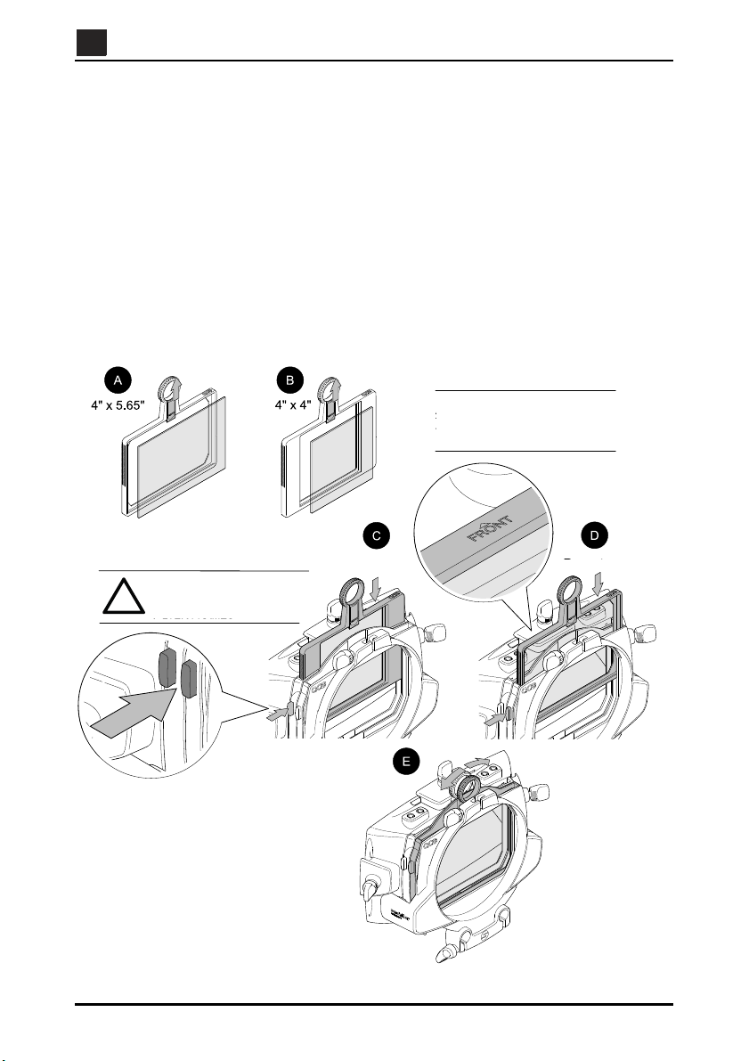
Assembling the filter frames
The Ace Matte Box comes with four filter frames. The filter frames are housed in two filter stages,
located between the sunshade and the rear clamping interface. The front filter stage is fixed, the
rear filter stage can be rotated through 90 degrees left or right.
To assemble the lens filter frames (see Fig. 4):
Push up the filter spring and align the filter in the frame, then release the spring to fix the
filter in place [A or B].
Slide the assembled filter frame into the filter stage. Slowly push the filter frame down,
whilst pressing the filter frame release button, until it is in position [C or D].
If required, rotate the rear filter frame 90 degrees. Push the handle of the filter frame to
the left or right until it is in position [E].
Fig. 4 Assembling the filter frames
-8-
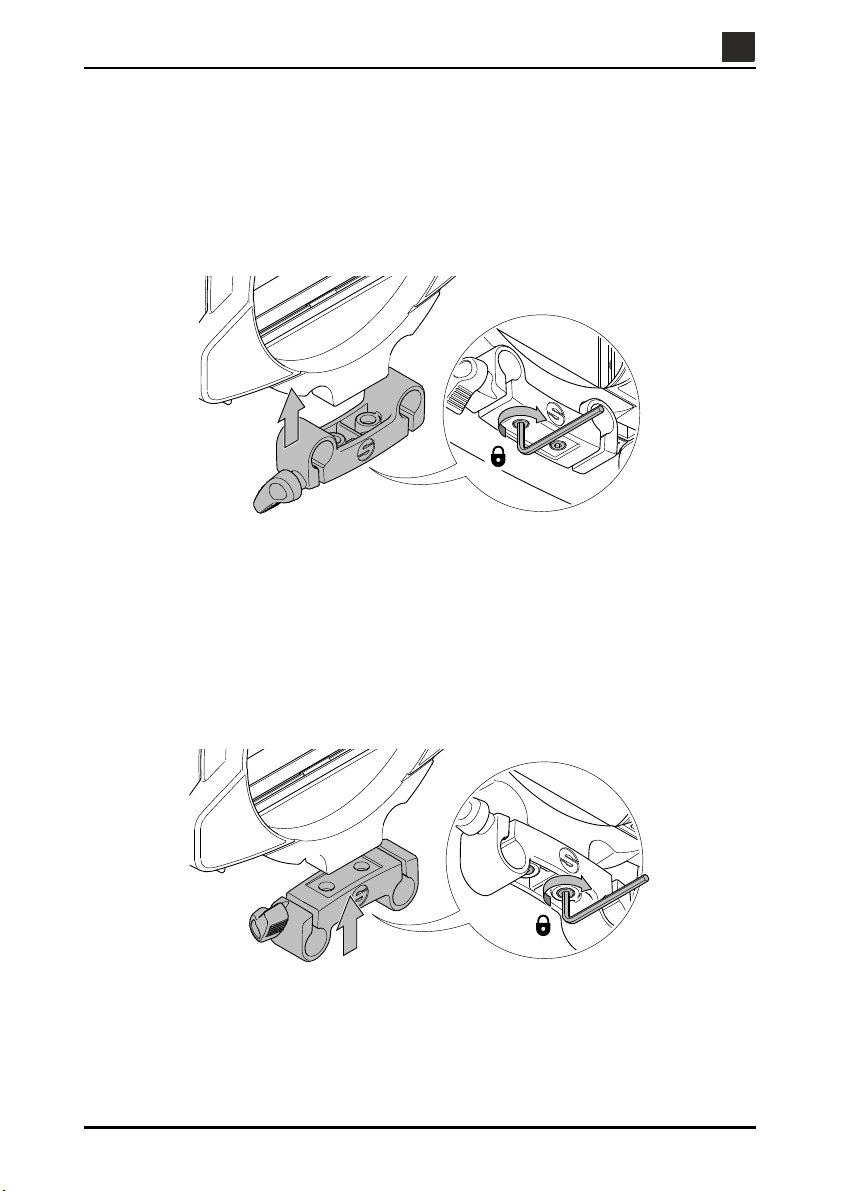
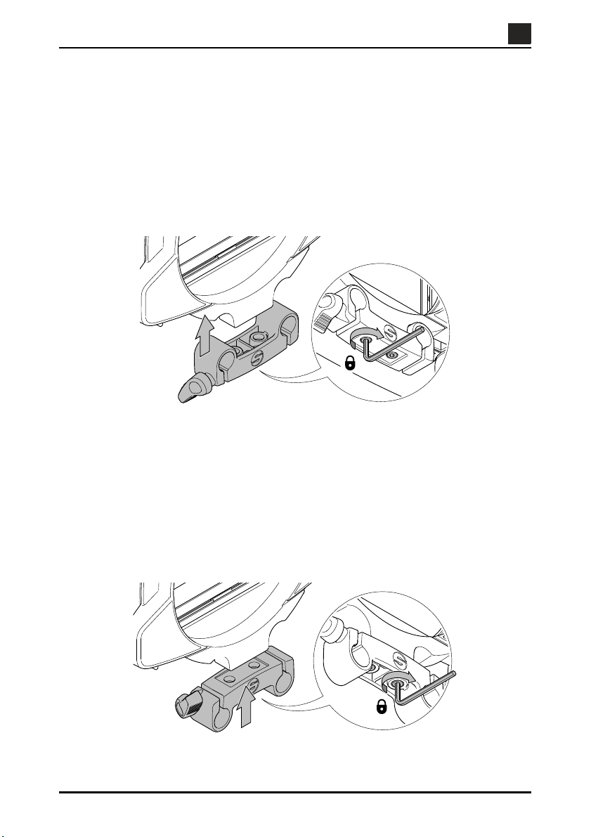
Assembling the rod bridge
The Ace Matte Box comes with a rod bridge attached. The rod bridge can be installed in two
positions, depending on the lens diameter used.
To assemble the rod bridge when using small diameter camera lenses (see Fig. 5):
Align the rod bridge with the recess on the sunshade. Using the 3 mm Allen key
supplied, tighten the two screws to secure the rod bridge in position.
Fig. 5 Assembling the rod bridge - small diameter camera lenses
EN
EN
To assemble the rod bridge when using large diameter camera lenses (see Fig. 6):
Align the rectangular recess of the rod bridge with the mounting holes on the sunshade.
Using the 3 mm Allen key supplied, tighten the two screws to secure the rod bridge in
position.
Fig. 6 Assembling the rod bridge - large diameter camera lenses
-9-
EN
EN
Operation
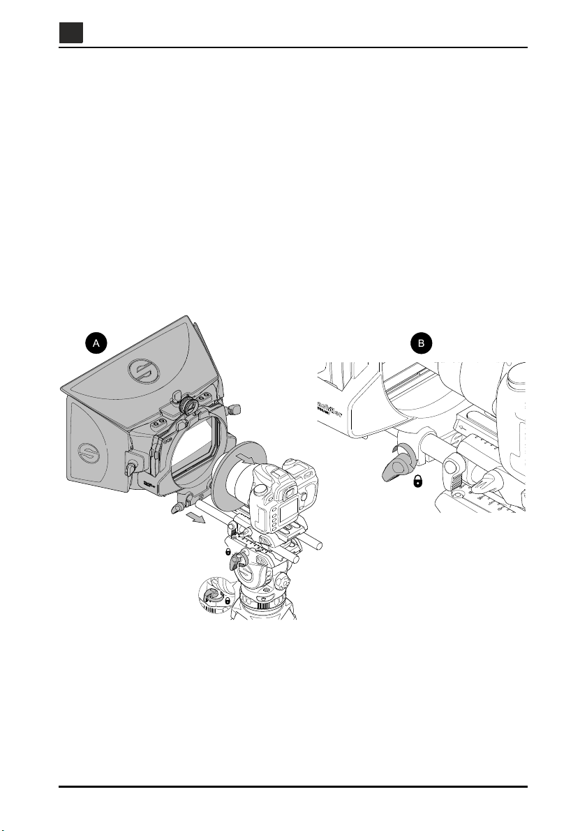
Mounting the Ace Matte Box
To mount the Ace Matte Box onto camera rods (see Fig. 7):
Ensure that the fluid head platform is level and apply both the horizontal and vertical
brakes [A].
If required, slide a neoprene ring over the camera lens [A].
Turn the rod bridge clamp knob counter-clockwise to loosen the clamp.
Align the rod bridge mounting holes with the support rods, then push the bridge forward
onto the rods [A].
Adjust the Ace Matte Box to the desired position, then turn the rod bridge clamp knob
clockwise to secure the bridge in position [B].
Fig. 7 Mounting the Ace Matte Box
-10-
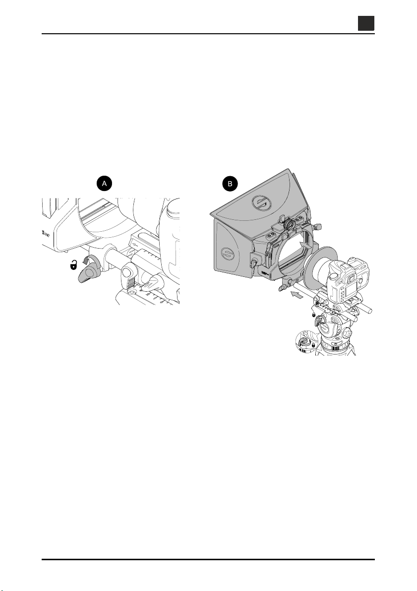
Removing the Ace Matte Box
To remove the Ace Matte Box from the camera rods (see Fig. 8):
Ensure that the fluid head platform is level and apply both the horizontal and vertical
brakes [B].
Turn the rod bridge clamp knob counter-clockwise to loosen the clamp [A], then slide the
Ace Matte Box away from the support rods [B].
If fitted, remove the neoprene ring from the camera lens [B].
EN
EN
Fig. 8 Removing the Ace Matte Box
-11-
EN
EN
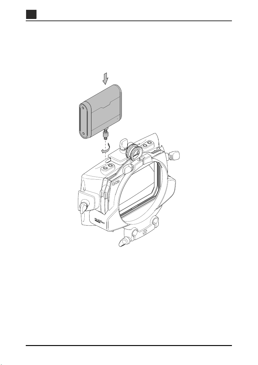
Mounting accessories to the Ace Matte Box
To mount accessories to the Ace Matte Box (see Fig. 9):
Insert the fixing screw of the accessory into the threaded hole on the accessory bar.
Secure the accessory to the Ace Matte Box.
Fig. 9 Mounting accessories to the Ace Matte Box
-12-

EN
EN
Maintenance
Cleaning
During indoor use, the only cleaning required should be a regular wipe over with a lint-free cloth.
Dirt accumulated during storage may be removed using a semi-stiff brush or vacuum cleaner.
Particular attention should be paid to the filter frames, the forward face of the sunshade and the
flag attachment points.
CAUTION! Do NOT use solvent or oil-based cleaners, abrasives or wire brushes to
Use out-of-doors under adverse conditions will require
washed off with fresh clean water at the earliest opportunity. Sand and dirt acts as an abrasive
and should be removed using a semi-stiff brush or vacuum cleaner.
ove accumulations of dirt, as these damage the protective surfaces.
em
r
Use only detergent-based cleaners.
special at
tention. Salt spray should be
-13-


DE
EN
Inhalt
Seite
Sicherheitshinweise. . . . . . . . . . . . . . . . . . . . . . . . . . . . . . . . . . . . . . . . . . . . . . . 16
Nutzung . . . . . . . . . . . . . . . . . . . . . . . . . . . . . . . . . . . . . . . . . . . . . . . . . . . . . . . . . 16
Gewährleistung . . . . . . . . . . . . . . . . . . . . . . . . . . . . . . . . . . . . . . . . . . . . . . . . . . 16
Technische Daten. . . . . . . . . . . . . . . . . . . . . . . . . . . . . . . . . . . . . . . . . . . . . . . . . 17
Bedienelemente . . . . . . . . . . . . . . . . . . . . . . . . . . . . . . . . . . . . . . . . . . . . . . . . . . 18
Montage. . . . . . . . . . . . . . . . . . . . . . . . . . . . . . . . . . . . . . . . . . . . . . . . . . . . . . . . . 20
Befestigung der Flags . . . . . . . . . . . . . . . . . . . . . . . . . . . . . . . . . . . . . . . . . . . . . . . . . . . 20
Montage der Filterhalter. . . . . . . . . . . . . . . . . . . . . . . . . . . . . . . . . . . . . . . . . . . . . . . . . . 22
Montage der Rod Bridge . . . . . . . . . . . . . . . . . . . . . . . . . . . . . . . . . . . . . . . . . . . . . . . . . 23
Bedienung. . . . . . . . . . . . . . . . . . . . . . . . . . . . . . . . . . . . . . . . . . . . . . . . . . . . . . . 24
Montage der Ace Matte Box . . . . . . . . . . . . . . . . . . . . . . . . . . . . . . . . . . . . . . . . . . . . . . 24
Demontage der Ace Matte Box . . . . . . . . . . . . . . . . . . . . . . . . . . . . . . . . . . . . . . . . . . . . 25
Wartung. . . . . . . . . . . . . . . . . . . . . . . . . . . . . . . . . . . . . . . . . . . . . . . . . . . . . . . . . 27
Reinigung. . . . . . . . . . . . . . . . . . . . . . . . . . . . . . . . . . . . . . . . . . . . . . . . . . . . . . . . . . . . . 27
-15-
EN
DE
Sicherheitshinweise
Lesen Sie sich vor Verwendung des
Produkts bitte die allgemeinen
Sicherheits- und Betriebshinweise
durch.
Drücken Sie zum Einsetzen und
Entnehmen der Filterhalter stets die
Tasten zur Filterhalter-Freigabe. Die
Nichtbeachtung dieser Anweisung
kann eine Beschädigung der Ace
Matte Box zur Folge haben.
Reinigen Sie das System regelmäßig
mit einem weichen Tuch und sanften
Reinigungsmittel.
Trocknen Sie das Produkt nach einer
Verwendung bei feuchten und nassen
Bedingungen.
Wenden Sie sich bei Schäden am
Produkt an Ihren SachtlerKundendienst vor Ort. Die
Kundendienststellen in Ihrer Nähe
finden Sie unter www.sachtler.com
Sachtler behält sich das Recht vor, Produktdesign und -leistung zu ändern. vorzunehmen.
Unter www.sachtler.com können Sie Ihr Produkt für die erweiterte Gewährleistung registrieren.
Scannen Sie den QR-Code, um
direkt zur Sachtler-Website zu
gelangen.
Nutzung
Die Ace Matte Box wurde für den
professionellen Einsatz entwickelt, um
Sonneneinstrahlung zu vermeiden bzw. Licht
und Reflexionen zu steuern. Sie muss auf
einem geeigneten Stativsystem mit Ace Base
Plate montiert werden, dessen Traglast für
den Aufbau geeignet ist.
Gewährleistung
In folgenden Fällen verliert die
Gewährleistung ihre Gültigkeit:
(a) Die Ace Matte Box wurde unsachgemäß
unter Missachtung der angegebenen
technischen Daten eingesetzt.
(b) Das Gehäuse der Ace Matte Box wurde
von unqualifiziertem Personal geöffnet.
-16-
Technische Daten
DE
EN
Ace Matte Box
0,88 kg (inkl. Top Flag, Side Flags
und Rod Bridge)
21 cm
27,8 cm (inkl. Top Flag)
28,5 cm
43 cm (inkl. Side Flags)
7,9 cm
12,3 cm (inkl. Flags)
1 kg
(jede Seite)
Ø14 cm
(max. Objektivdurchmesser)
Top Flag
32,7 cm
14,7 cm
Rod Bridge
Ø15 mm (Durchmesser der
Rohre)
8,5 cm (Konfiguration für ein
Objektiv mit kleinem
Durchmesser – Rohrmittelpunkt
bis Mittelpunkt der rückseitigen
Klemmbefestigung)
10,9 cm (Konfiguration für ein
Objektiv mit großem
Durchmesser – Rohrmittelpunkt
bis Mittelpunkt der rückseitigen
Klemmbefestigung)
Side Flags
18,8 cm
12,7 cm
Filterhalter
10 cm (quadratische Filter)
10 cm (rechteckige Filter)
10 cm (quadratische Filter)
14 cm (rechteckige Filter)
-17-
EN
DE
Bedienelemente
Top Flag
Klemme der Top Flag
Zubehörleiste
Filterhalter
Side Flag
Klemme der Side Flag
Rod Bridge
Klemme des Rohrs
Donuts (Neopren)
Taste zur
FilterhalterFreigabe
Rückseitige
Klemmbefestigung
Die Ace Matte Box wurde für den professionellen Einsatz mit DSLR- und HDV-Kameras
entwickelt. Sie umfasst verstellbare Top und Side Flags, verschiedene Befestigungspunkte,
zwei Zubehörleisten, 2-fach-Filterbühne, eine rückseitige Klemmbefestigung und eine Rod
Bridge.
Abb. 1 Bedienelemente
-18-

DE
EN
Top und Side Flags / Klemmen
Die Ace Matte Box ermöglicht die Anbringung und bedarfsgerechte Ausrichtung von Top
und Side Flags. Die Klemme der Top Flag befindet sich am oberen Rand zwischen den zwei
ubehörleisten. Die Klemmen der Side Flag befinden sich an der linken und rechten Seite
Z
der Sunshade.
Zubehörleiste
Die zwei Zubehörleisten ermöglichen die Befestigung von Zubehör, beispielsweise von
Leuchten oder Mikrofonen. Beide Zubehörleisten sind mit Gewindebuchsen 1/4” 20 UNC
ausgestattet. Sie befinden sich am oberen Rand, zu beiden Seiten der Klemme der Top Flag.
Filterbühne
Eine 2-fach-Filterbühne, eine davon drehbar, dient der Aufnahme von zwei Filterhaltern. Sie
befindet sich zwischen Sonnenschutzblende und rückseitiger Klemmbefestigung.
Filterhalter
Die zwei Filterhalter sind für die Aufnahme von Filtern in zwei verschiedenen Größen ausgelegt
(4 x 4" und 4 x 5,65").
Tasten zur Filterhalter-Freigabe
Durch Drücken der jeweiligen Taste zur Filterhalter-Freigabe können die Filterhalter eingesetzt
bzw. entnommen werden. Die Tasten befinden sich links neben der Filterbühne.
Rückseitige Klemmbefestigung
Die rückseitige Klemmbefestigung ermöglicht die Anbringung eines Reduzierrings.
Rod Bridge
Mithilfe der Rod Bridge wird die Ace Matte Box auf der Ace Base Plate montiert. Die Rod Bridge
kann je nach Durchmesser der verwendeten Objektive in zwei verschiedenen Positionen
installiert werden.
Montage der Ace Matte Box
Die Ace Matte Box wird direkt auf den an der Ace Base Plate angebrachten Rohren montiert.
Dazu wird die Rod Bridge der Ace Matte Box auf die Rohre aufgeschoben, bis das Objektiv
positioniert ist.
Zubehör
Um einen Schutz vor Streulicht zu gewährleisten, sind im Lieferumfang der Ace Matte Box zwei
Donuts enthalten. Sobald sich die Kamera in Position befindet, kann der Donut über das
Objektiv bis an die rückseitige Klemmbefestigung geschoben werden.
Die Ace Matte Box umfasst ebenfalls einen 3Demontage der Rod Bridge.
mm-Inbus-Schlüssel für die Montage und
-19-
EN
DE
Montage
Befestigung der Flags
Die Ace Matte Box umfasst zwei Side Flags und eine Top Flag. Die Side Flags werden mithilfe
von Klemmen an beiden Seiten der Matte Box befestigt. Die Top Flag wird über eine Klemme
am oberen Rand befestigt.
Befestigen Sie die Side Flags wie folgt (siehe Abb. 2):
Drehen Sie den Klemmhebel der Side Flag, falls erforderlich, gegen den Uhrzeigersinn,
um die Klemme zu lösen.
Führen Sie die Aussparung an der Side Flag ein [A] und ziehen Sie dann den seitlichen
Klemmhebel an [B], bis die Side Flag sicher befestigt ist.
Stellen Sie den Winkel der Side Flag bedarfsgerecht ein [C] und ziehen Sie
anschließend den seitlichen Klemmhebel fest [B].
Abb. 2 Befestigung der Side Flags
-20-
Befestigen Sie die Top Flag wie folgt (siehe Abb. 3):
Drehen Sie den Klemmhebel der Top Flag, falls erforderlich, gegen den Uhrzeigersinn,
um die Klemme zu lösen.
Führen Sie die Aussparung an der Top Flag ein [A] und ziehen Sie dann den oberen
Klemmhebel an [B], bis die Top Flag sicher befestigt ist.
Stellen Sie den Winkel der Top Flag bedarfsgerecht ein [C] und ziehen Sie anschließend
den oberen Klemmhebel fest [B].
DE
EN
Abb. 3 Befestigung der Top Flag
-21-
EN
DE
Montage der Filterhalter
!
VORSICHT: DRÜCKEN SIE IMMER
DIE FILTER-FREIGABETASTEN,
WENN SIE FILTERHALTER
EINSETZEN BZW. ENTNEHMEN.
HINWEIS: STELLEN SIE SICHER,
DASS DER PFEIL ÜBER DEM TEXT
'FRONT' AN DER OBERSEITE DES
FILTERHALTERS ZUR VORDERSEITE
DER ACE MATTE BOX ZEIGT.
Hinterer Einschub
Vorderer Einschub
Im Lieferumfang der Ace Matte Box sind vier Filterhalter enthalten. Die Filterhalter werden in der
2-fach-Filterbühne untergebracht. Die hintere Filtereinschub kann bis zu 90 Grad nach links
bzw. rechts gedreht werden, der vordere Filtereinschub ist nicht drehbar.
Gehen Sie zur Befestigung der Filter im Filterhalter wie folgt vor (siehe Abb. 4):
Drücken Sie die Filterfeder nach oben und richten Sie den Filter am Halter aus. Geben
Sie dann die Feder wieder frei, um den Filter in seiner Position zu blockieren [A oder B].
Schieben Sie den Filterhalter in die Filterbühne ein. Schieben Sie dazu den Filterhalter
bei gedrückt gehaltener Filterhalter-Freigabetaste vorsichtig bis zu gewünschten
Position nach unten [C oder D].
Sofern erforderlich, drehen Sie den hinteren Filterhalter bis zu 90 Grad. Drücken Sie den
Hebel des Filterhalters nach links bzw. nach rechts, bis er hörbar einrastet [E].
Abb. 4 Montage der Filterhalter
-22-
DE
EN
Montage der Rod Bridge
An die Ace Matte Box ist standardmäßig eine Rod Bridge angebracht. Die Rod Bridge kann
je nach Durchmesser der verwendeten Objektive in zwei verschiedenen Positionen installiert
werden.
Gehen Sie zur Montage der Stützbrücke bei Verwendung von Objektiven mit kleinem
Durchmesser wie folgt vor (siehe
Richten Sie die Rod Bridge an der Aussparung aus. Ziehen Sie mithilfe des
mitgelieferten 3-mm-Inbus-Schlüssels die zwei Schrauben fest, um die Rod
Bridge sicher in ihrer Position zu befestigen.
Abb. 5 Montage der Rod Bridge – Objektive mit kleinem Durchmesser
Abb. 5):
Gehen Sie zur Montage der Rod Bridge bei Verwendung von Objektiven mit großem
Durchmesser wie folgt vor (siehe
Richten Sie die rechteckige Aussparung an der Rod Bridge an den Montagelöchern aus.
Ziehen Sie mithilfe des mitgelieferten 3-mm-Inbus-Schlüssels die zwei Schrauben fest,
um die Rod Bridge sicher in ihrer Position zu befestigen.
Abb. 6 Montage der Rod Bridge – Objektive mit großem Durchmesser
Abb. 6):
-23-
 Loading...