

Sachtler 75/2 D HD User Manual
www.sachtler.com
EN
Part No. S2034-0001
ENG 75/2 D HD Tripod
ENG 75/2 D HD
Tripod
DE

Copyright © 2014
All rights reserved.
Original Instructions: English
All rights reserved throughout the world. No part of this document may be stored in a retrieval system,
transmitted, copied or reproduced in any way, including, but not limited to, photocopy, photograph,
magnetic or other record without the prior agreement and permission in writing of the Vitec Group plc.
Disclaimer
The information contained in this manual is believed to be correct at the time of printing. Vitec Videocom
Ltd reserves the right to make changes to the information or specifications without obligation to notify any
person of such revision or changes. Changes will be incorporated in new versions of the publication.
We are making every effort to ensure that our manuals are updated on a regular basis to reflect changes
to product specifications and features. Should this manual not contain information on the core functionality
of your product, please let us know. You may be able to access the latest revision of this manual from our
website.
Vitec Videocom Ltd reserves the right to make changes to product design and functionality without
notification.
Trademarks
All product trademarks and registered trademarks are the property of The Vitec Group Plc.
All other trademarks and registered trademarks are the property of their respective companies.
Published by:
Vitec Videocom Ltd
Supports Technical Publications Department
Western Way, Bury St Edmunds
Suffolk IP33 3TB
United Kingdom
Email: technical.publications@vitecgroup.com

1
EN
Contents
Safety. . . . . . . . . . . . . . . . . . . . . . . . . . . . . . . . . . . . . . . . . . . . . . . . . 2
Intended Use. . . . . . . . . . . . . . . . . . . . . . . . . . . . . . . . . . . . . . . . . . . 2
Components . . . . . . . . . . . . . . . . . . . . . . . . . . . . . . . . . . . . . . . . . . . 3
ENG 75/2 D HD Tripod. . . . . . . . . . . . . . . . . . . . . . . . . . . . . . . . 3
Mid-level Spreader 75 HD (optional S2038-1000) . . . . . . . . . . . 4
Ground Spreader SP 75 (optional 7001) . . . . . . . . . . . . . . . . . . 4
Assembly . . . . . . . . . . . . . . . . . . . . . . . . . . . . . . . . . . . . . . . . . . . . . 5
Setting up the Tripod . . . . . . . . . . . . . . . . . . . . . . . . . . . . . . . . . 5
Attaching the mid-level spreader 75 HD. . . . . . . . . . . . . . . . . . . 7
Attaching the rubber feet 75 . . . . . . . . . . . . . . . . . . . . . . . . . . . . 7
Attaching the ground spreader SP 75. . . . . . . . . . . . . . . . . . . . . 8
Setting up the mid-level spreader 75 HD . . . . . . . . . . . . . . . . . . 8
Setting up the ground spreader SP 75 . . . . . . . . . . . . . . . . . . . . 9
Transportation . . . . . . . . . . . . . . . . . . . . . . . . . . . . . . . . . . . . . . . . 10
Attaching the bungee cord hook. . . . . . . . . . . . . . . . . . . . . . . . 10
Maintenance . . . . . . . . . . . . . . . . . . . . . . . . . . . . . . . . . . . . . . . . . . 11
General. . . . . . . . . . . . . . . . . . . . . . . . . . . . . . . . . . . . . . . . . . . 11
Cleaning . . . . . . . . . . . . . . . . . . . . . . . . . . . . . . . . . . . . . . . . . . 11
Adjusting the leg clamps. . . . . . . . . . . . . . . . . . . . . . . . . . . . . . 12
Technical Specification . . . . . . . . . . . . . . . . . . . . . . . . . . . . . . . . . 13
ENG 75/2 D HD Tripod (S2034-0001) . . . . . . . . . . . . . . . . . . . 13
Mid-level Spreader 75 HD (optional S2038-1000) . . . . . . . . . . 13
Ground Spreader SP 75 (optional 7001) . . . . . . . . . . . . . . . . . 13
General Notices . . . . . . . . . . . . . . . . . . . . . . . . . . . . . . . . . . . . . . . .14
Declaration of Conformity. . . . . . . . . . . . . . . . . . . . . . . . . . . . . .14
Warranty. . . . . . . . . . . . . . . . . . . . . . . . . . . . . . . . . . . . . . . . . . .14
2
EN
Safety
Important information on the safe installation and operation of this
product. Read this information before operating the product. For
your personal safety, read these instructions. Do not operate the
product if you do not understand how to use it safely. Save these
instructions for future reference.
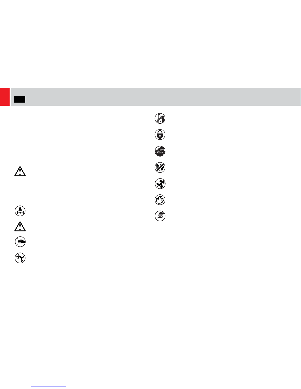
Warning Symbols Used in these Instructions
Safety cautions are included in these instructions. These safety
instructions must be followed to avoid possible personal injury and
avoid possible damage to the product.
Health and Safety
Intended Use
The ENG 75/2 D HD tripod is a two-stage aluminium tripod with fast
action clamps for easy setup. The optional mid-level spreader 75 HD
features a fast-action clamp with a profile allowing the tripod to be set
to two predefined footprints. The optional ground spreader SP 75 can
be adjusted to suit other footprints as required by the shooting
environment.
WARNING! Risk of personal injury or injury to others. All
personnel must be fully trained and adhere to correct manual
handling techniques and Healthy & Safety regulations. It is
the responsibility of the local organisation to enforce safe
working practices at all times.
WARNING! Do not exceed the maximum payload.
WARNING! Tripod spike feet can be dangerous, take care
handling.
WARNING! Finger entrapment. Avoid trapping fingers
when collapsing and extending the tripod.
WARNING! Trip hazard. Set the tripod footprint to suit the
shooting environment.
WARNING! Toppling hazard. Do not leave unattended.
Keep out of reach of children.
CAUTION! Do not over tighten the tripod leg locks. When in
use always lock the tripod leg clamps to prevent the tripod
collapsing.
CAUTION! Hold the camera securely when (a) mounting or
dismounting from the fluid head (b) making adjustments to
the tripod height or footprint.
CAUTION! Do not place your foot or heavy weight onto the
spreader.
CAUTION! Always remove the camera before transporting.
Clean regularly using a soft cloth and mild detergent.
Dry the product after use in wet conditions.
3
EN
Components
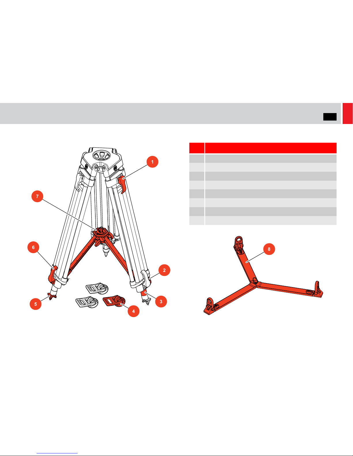
ENG 75/2 D HD Tripod
.
No. Description
1 Upper leg clamp lever
2 Bungee cord hook
3 Safety sleeve
4 Rubber feet 75 x 3 (optional)
5 Double-spiked foot
6 Lower leg clamp lever
7 Mid-level spreader 75 HD (optional)
8 Ground spreader SP (optional)

4
EN
Components
Mid-level Spreader 75 HD (optional S2038-1000) Ground Spreader SP 75 (optional 7001)
No. Description
1 HIGH/LOW profile knob
2 Pull up ring
3 Spreader lock
4 Spreader attachment hook
5 Red attach/release button
6 Spreader arm
No. Description
1 Spreader lock
2 Pull up ring
3 Spreader foot
4 Spreader arm
5
EN
Assembly
Setting up the Tripod
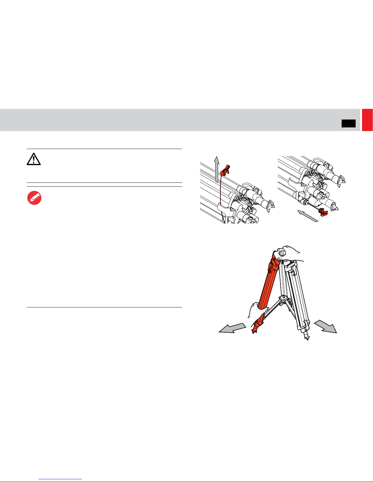
6. Detach the bungee cord hook to release the legs.
7. Holding the tripod upright, open out the legs and set the footprint
of the tripod to suit the shooting environment.
CAUTION! Use the spreader to ensure the tripod legs are
spread sufficiently , so that the Centre of Gravity of the tilted
payload remains within the footprint of the tripod. Use the
tie-down hook on the tripod for additional stability.
Notes
1. The following procedure refers to a two-stage tripod
fitted with a mid-level spreader (if necessary, refer to
Attaching the mid-level spreader 75 HD on page 7).
2. ALWAYS use the spreaders to increase the rigidity of
the tripod.
3. At the fullest extension of the spreader and with all legs
fully retracted, the tripod can be used at its lowest
operating height. Although the tripod can be set up
lower than this without the spreader, it is NOT
recommended as the tripod geometry becomes
unstable.
4. Do not use spikes on hard ground or delicate surfaces.
5. The tie-down hook can be used either to hang a
backpack on for additional stability or as a storage point
for items.
6
EN
Assembly
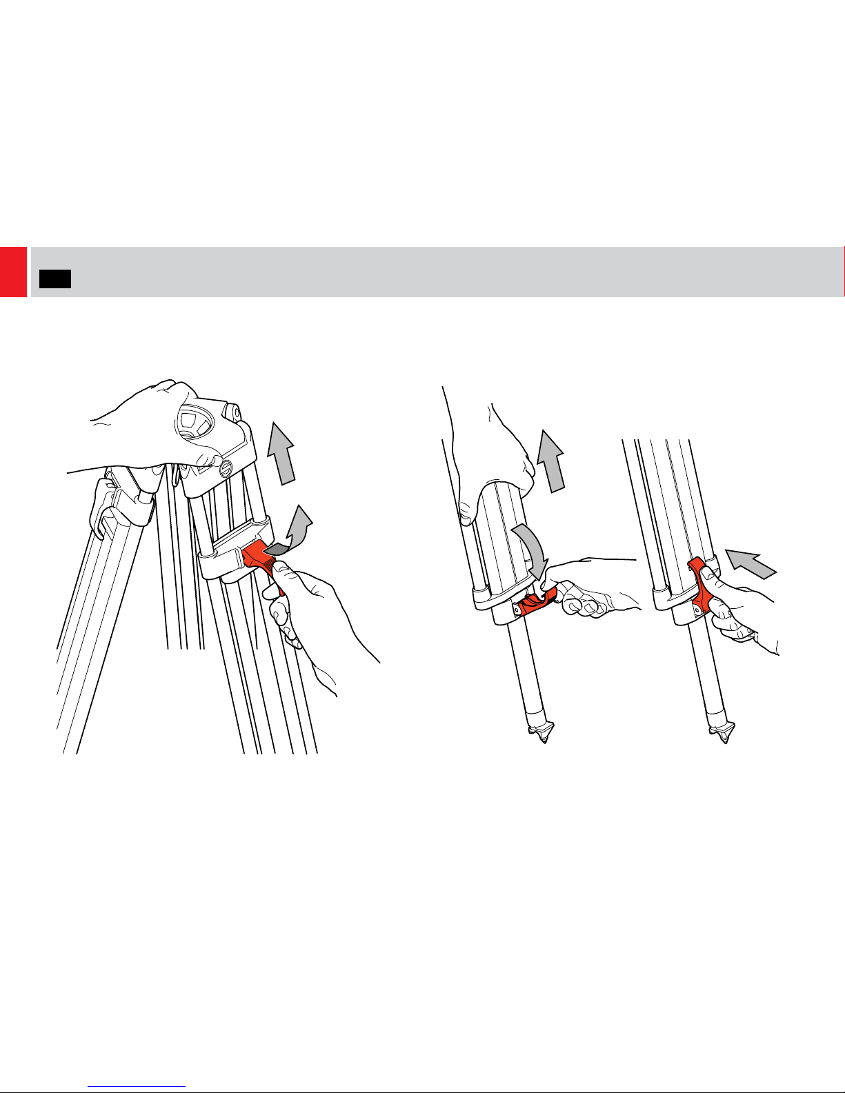
8. Extend the upper stage by lifting the clamp levers and adjusting
the height of the tripod as required. When complete, push down
the clamp levers, until they snap into the ‘locked’ position.
9. Adjust the operating height by flipping down the leg clamp levers
on the lower stage and pulling the tripod up to the desired height.
When complete, push up the lower stage clamp levers, until they
snap into the ‘locked’ position.
7
EN
Assembly
Attaching the mid-level spreader 75 HD
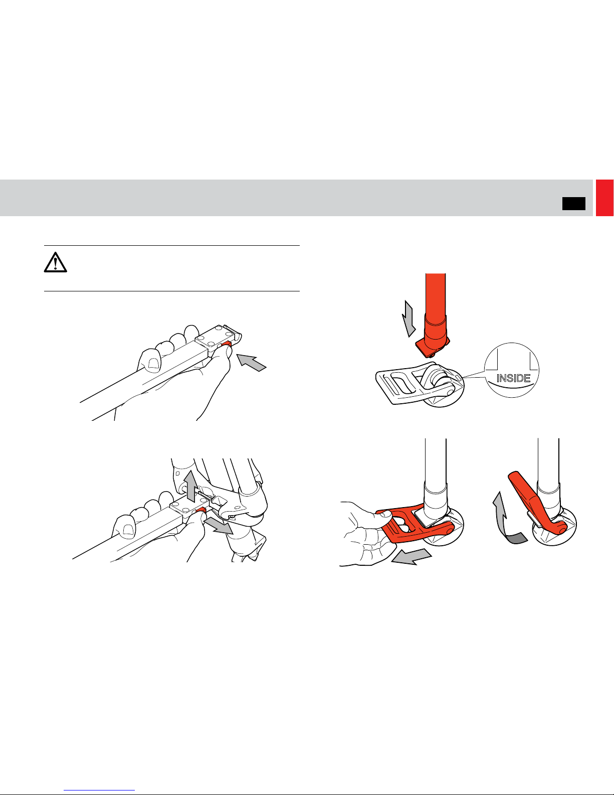
1. Hold each spreader arm between thumb and forefinger, then using
the other hand squeeze the red attachment button.
2. Align the spreader hook with the tripod leg from underneath and
release the red attach/release button to lock the spreader arm in
place.
Attaching the rubber feet 75
1. Place the rubber foot between the spikes. Check the markings on
the foot for orientation. The ‘INSIDE’ marking must be turned
towards the centre of the tripod.
2. Push down firmly on the leg, put your fingers through the larger
loop, and pull the rubber pull-loop over the latching nose.
CAUTION! Ensure that the red attach/release button is fully
out after attaching the spreader to the tripod. Failure to
attach the spreader correctly could cause damage to the
equipment.
8
EN
Assembly
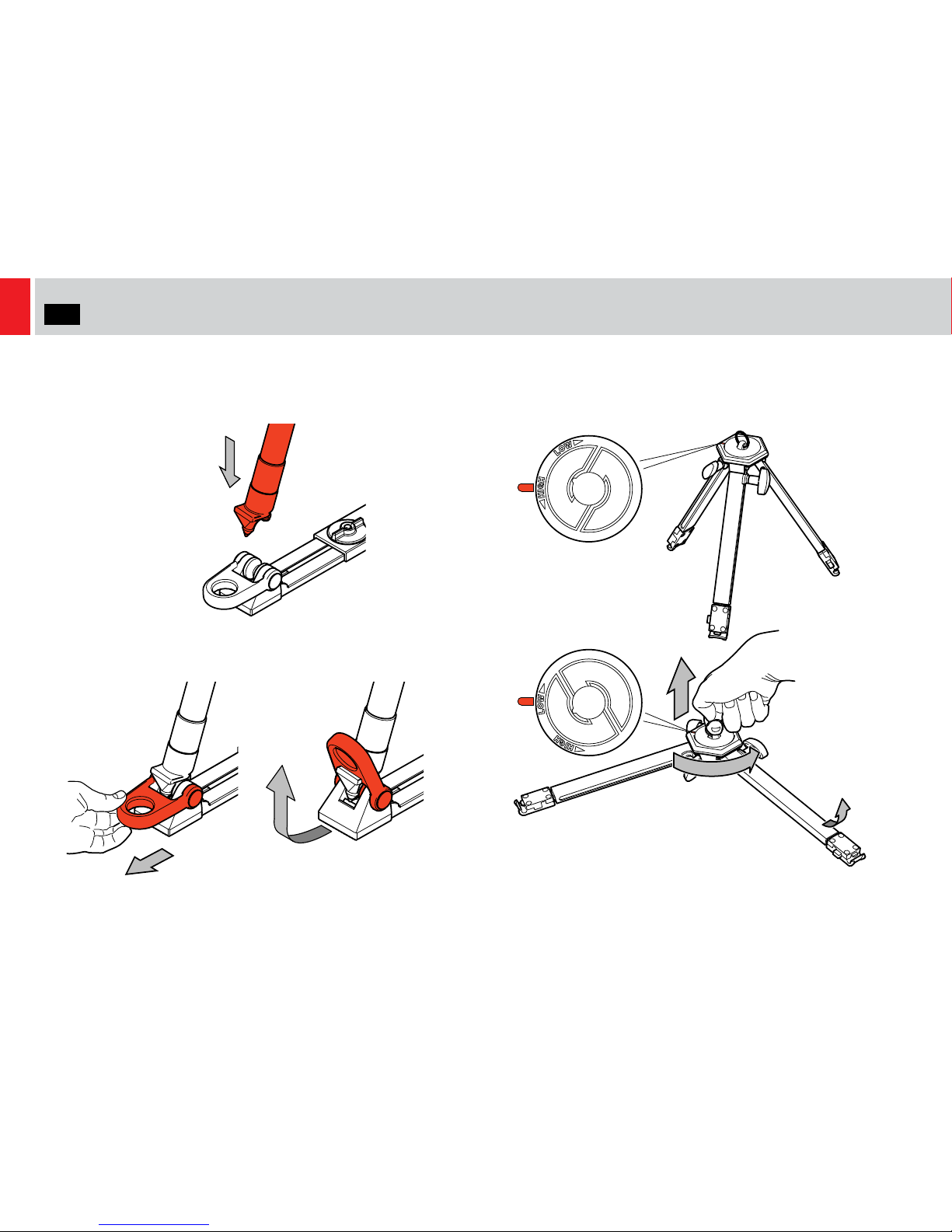
Attaching the ground spreader SP 75
1. Place the ground spreader on the floor and open out the legs.
Place the spikes of the tripod between the foot moulding on the
ground spreader.
2. Push down firmly on the leg, put your fingers through the larger
loop, and pull the rubber pull-loop over the latching nose.
Setting up the mid-level spreader 75 HD
1. Pull up the ring in the centre of the spreader. Adjust the profile
setting to either HIGH (45°) or LOW (flat) and arrest the tripod legs
in position.
 Loading...