

Sachtler 0477, 0450 User manual
Manual
Benutzerinformation
Fluid Head
Fluidkopf
6

© by sachtler®. Alle Rechte vorbehalten / All rights reserved
Originalbetriebsanleitung/Original User Manual
Version: 2.3/12/13
Ausgabedatum / Issue date: 12/13
Bestellnr. / Order no.: S2001-4980
sachtler
®
Vitec Group Videocom Division
www.vitecgroup.com
Erfurter Strasse 16 Postfach / P.O.BOX 2039
D-85386 Eching D-85380 Eching
Germany Germany
Telefon: (+49 89) 321 58 200
Telefax: (+49 89) 321 58 227
E-Mail: contact@sachtler.de
Internet: http://www.sachtler.com

- I -
FSB 6
Table of contents
1 Safety instructions / General Information.............................1
2 Operating elements..............................................................2
3 Operation..............................................................................3
3.1 Intended use ................................................................3
3.2 Moving of the pan bar ..................................................3
3.3 Levelling of the fluid head ............................................4
3.4 Mounting of the camera and / or plate.........................4
3.5 Counterbalancing of the camera..................................6
3.6 Setting of the drag........................................................6
3.7 Brakes ..........................................................................7
3.8 Change of battery ........................................................7
3.9 Transport setting of drag, counterbalance
and brakes ...................................................................7
3.10 Flat Base Mount...........................................................8
4 Technical Data......................................................................8
5 Accessories ..........................................................................9
5.1 Camera plates..............................................................9
5.2 Pan bars.....................................................................10
6 Inspection & Cleaning ........................................................10
7 Warranty.............................................................................10

Inhaltsverzeichnis
1 Sicherheitshinweise / Grundlegende Hinweise ..................11
2 Bedienelemente .................................................................12
3 Betrieb ................................................................................13
3.1 Bestimmungsgemäße Verwendung ...........................13
3.2 Schwenkarmverstellung .............................................13
3.3 Nivellieren des Fluidkopfes ........................................14
3.4 Entnehmen und Einsetzen der Kameraplatte ............14
3.5 Einstellen der Kamerabalance ...................................16
3.6 Einstellen der Dämpfung............................................17
3.7 Bremsen.....................................................................17
3.8 Austausch der Batterie...............................................17
3.9 Transportstellung von Dämpfung, Gewichtsaus-
gleich und Bremsen ...................................................18
3.10 Flachboden ................................................................18
4 Technische Daten...............................................................19
5 Zubehör ..............................................................................20
5.1 Kameraplatten............................................................20
5.2 Schwenkarme ............................................................21
6 Inspektion & Pflege ............................................................22
7 Gewährleistung ..................................................................22
- II -
FSB 6

ManualFSB 6
- 1 -
1 Safety instructions / General Information
-> Before using the fluid head read the manual.
-> Before mounting the fluid head on the tripod, check if the tri-
pod has a safe standing and if the tripod leg extensions are
clamped.
-> Before releasing the clamping screw on the fluid head (with
a mounted camera), the tripod must be secured against fall
over.
-> Before releasing the vertical brake (at a non balanced
camera set up) or the clamping of the camera-/balance plate
the camera must be secured against sudden movement,
otherwise there may be a danger of finger trapping.
-> During camera tilt movements with extreme tilt angles there
may be a danger of finger trapping between top-/balance
plate and housing for users and third persons.
- 2 -
FSB 6Manual
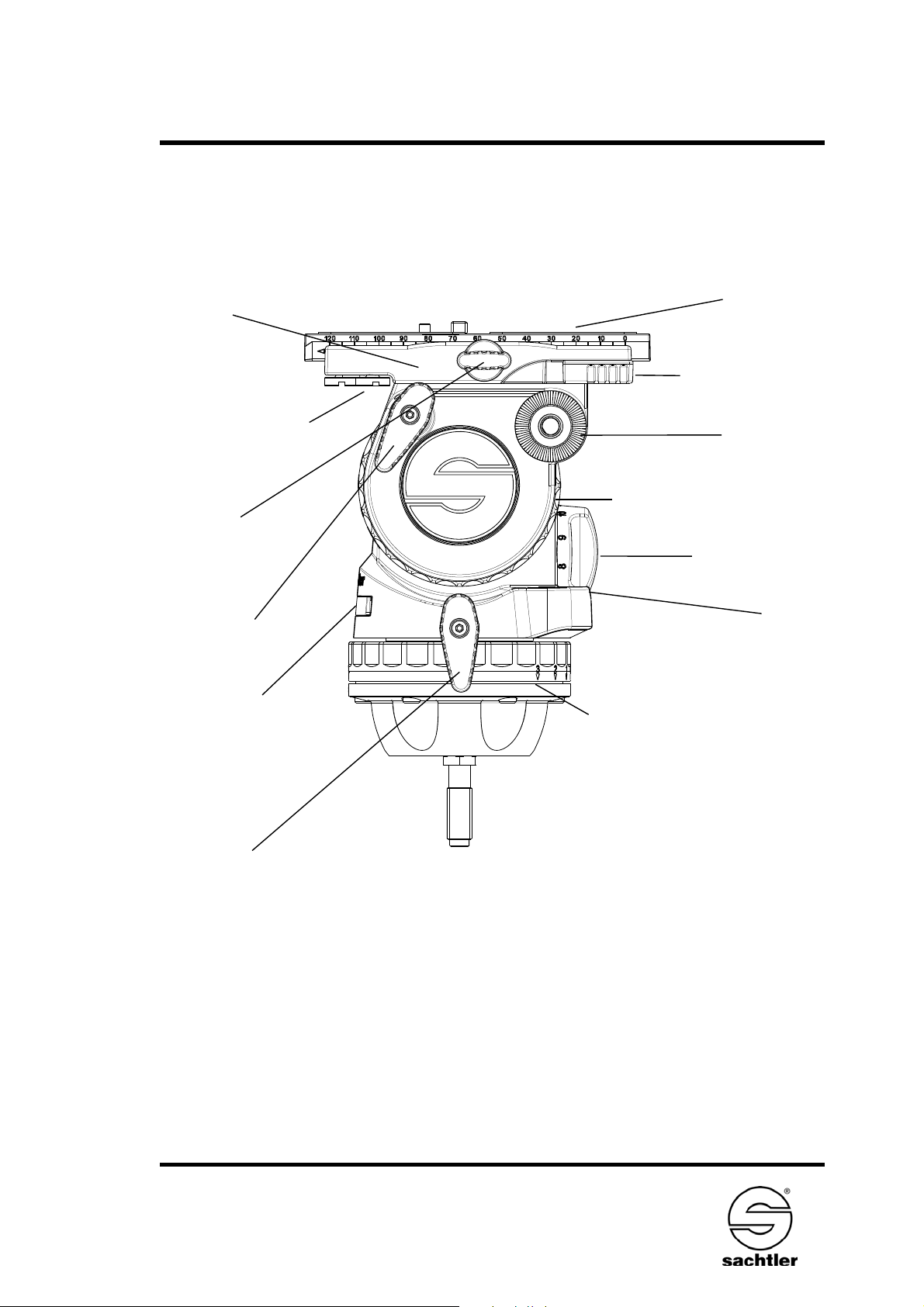
2 Operating elements
Horizontal setting of fluid drag
Vertical brake
Vertical setting of fluid
drag
Horizontal brake
Rosette for
pan bar
Camera
plate
Parking position
for camera screws
not in use
Camera Release
Safety Lock
Clamping
screw
of camera
plate
Counterbalance
adjustment
Bubble
A. FSB 6 with sideload-plate
Top plate
Battery compartment
Manual
- 3 -
FSB 6
3 Operation
3.1 Intended Use
This fluid head was developed to enable pan- and tilt
movements of cameras. The maximum payload is specified
in chapter 4.
3.2 Moving of the pan bar
Open the clamping screw (black wing screw) of the pan bar
and move the pan bar into the desired position. Close the
clamping screw of the pan bar. During transportation the
pan bar can be moved next to the tripod legs.
Caution:
Open the clamping screw of the pan bar far
enough. The teeth of the pan bar clamp should not clatter
while moving the pan bar. However, a plastic protector prevents against wear of the metal toothed ring. Make sure
that the teeth interleave with each other when closing the
clamping lever of the pan bar.
Use of the enclosed pan bar on the left side of the fluid
head is also possible. The pan bar has to be removed from
the head and the black plastic cap on its top should be
opened and removed with a coin or screw driver. The toothed clamp should be removed and relocated. The plastic
cap needs to be tightened again.
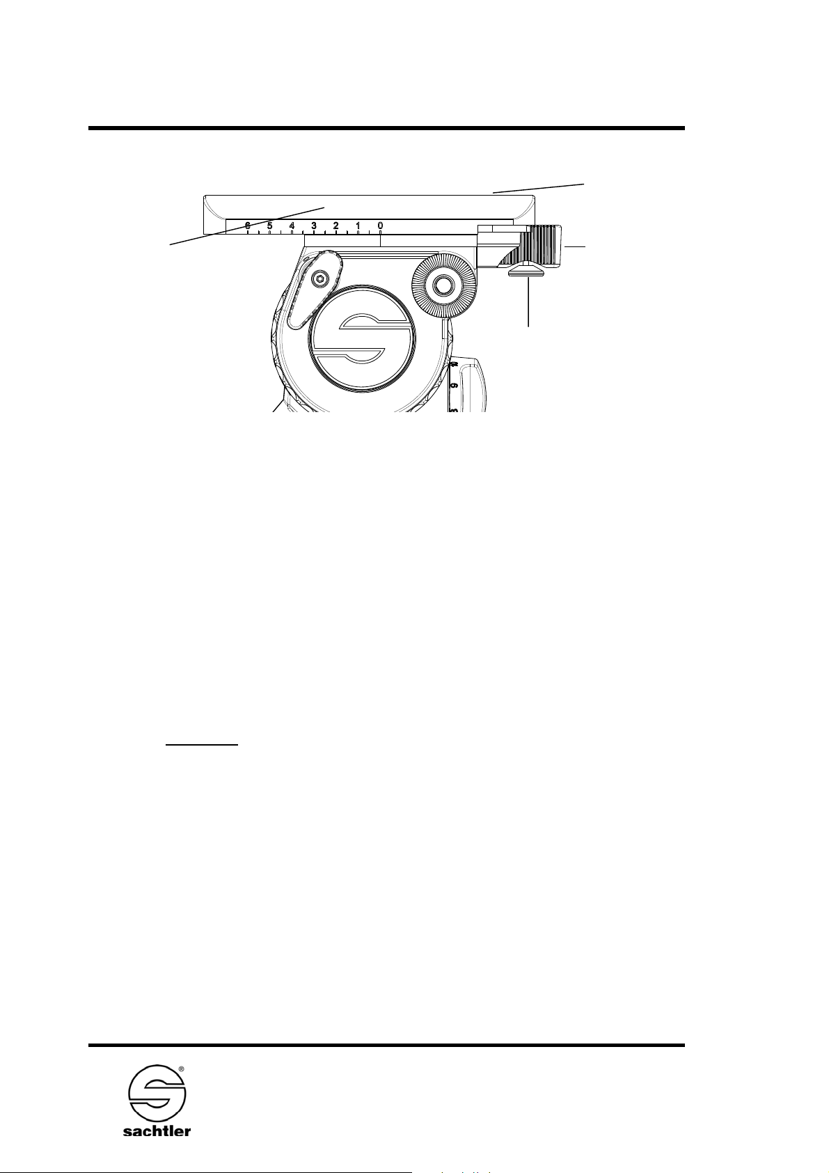
B. FSB 6 T - FSB 6 with Touch & Go plate
Balance plate
(clamping of the
balance plate
backside)
Cameraplate
Camera Release
Safety Lock of Touch
& Go System
Lever
Locking of
Touch & Go
System

- 4 -
FSB 6Manual
3.3 Levelling of the fluid head
Apply the vertical brake and hold the camera with one
hand. Open the clamping screw of the fluid head and move
the head in such a way, that the bubble moves into the
level´s black circle. Tighten the clamping screw firmly.
Touch Bubble
The FSB 6 has a self illuminating Touch Bubble which allo-
ws easy levelling even under unfavourable lighting conditions. The illumination is activated by strong tapping on the
bubble. The bubble will glow up to 20 seconds.
3.4 Mounting of the camera and / or plate
A. FSB 6 with side load clamping mechanism
-> Apply the horizontal and vertical brake.
-> Hold the camera and / or plate with one hand.
-> Release the clamping screw of camera plate.
-> Shift the red Camera Release Safety Lock forward.
-> The camera(plate) is now unlocked and can be remo-
ved from the fluid head.
-> Attach the camera plate to the camera. Please pay
attention to the arrow on the camera plate.This arrow is
indicating the direction of the lens. (Also see paragraph
5.1 “camera plates”).
-> For mounting the camera(plate) onto the fluid head
place the camera plate´s dovetail in the dovetail´s guiding on the head (see picture below, arrow A).
-> Lower the camera(plate) until the snap lock catches the
camera plate. This is detected by an audible clicking
(arrow B).
-> The camera(plate) is now mounted securely.
-> Lock the clamping screw of the camera plate after
counterbalancing the camera (see also paragraph 3.4
“counterbalancing the camera”).
 Loading...