

Page 1

(SJ
SACHS
Repair Instructions No. 4072.8 E
SACHS
SA
2-440
Snowmobile Engine
Edition December
FICHTEL & SACHS
1970
AG . D-8720
SCHWEINFURT
Page 2

Page 3
CONTENTS
Introduction
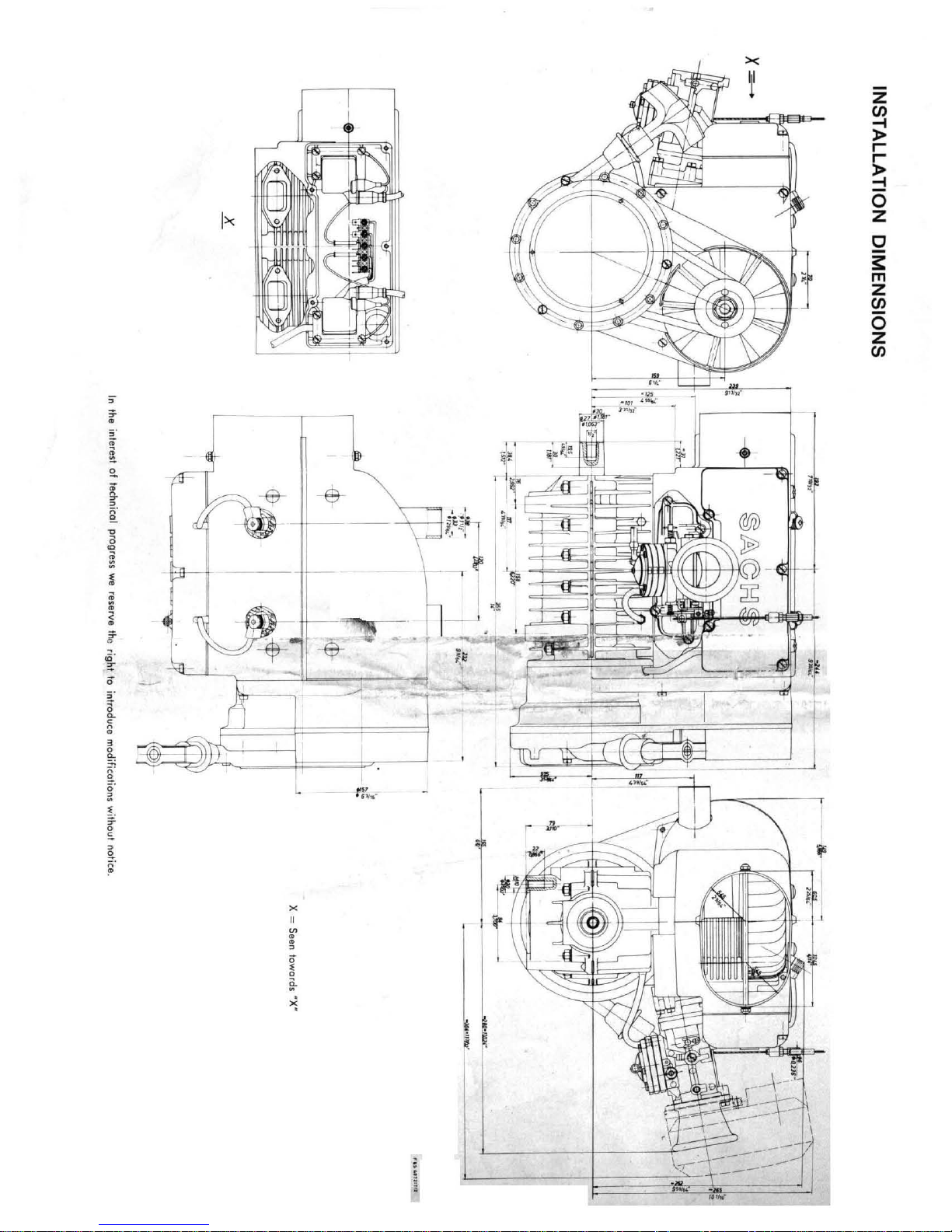
In
stallation
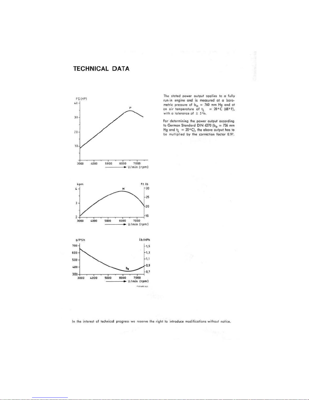
Te
chnical
R
epoi
Di
smontling the engine
Work
Assembling
Engine with BaSCH Bendix.
In
structions
Instructions
end
Test-running
loying
lubricotion
Tightening
Trouble-s
dimensions
deta
r tools
end
ossembly
on
ind
ivi
dual
components
Replocing
Reploci
Receil
Mogneto
Replocing ignition
Replocing
Corburettor
Decorbonizing
Ignition timing
Operation,
Storter
BOSCH Bendix-pinion
up
hooting
crankshaft
ng
fan shoft
starter
. . . . . . . .
generator
the
flonged
. . . . . . . . . . . . . . . . . . . . . . . . . . .
the
the
Fa
end
ond
end
the
engine
ond
torques
engine
wiring
. . . . . . . . . . . . . _
........
mointenance
ults . . . . . . . . . . . . . . . . . . . . . . .
diegram
wiring
diogram
running-in
.. _ ...
moi
ntenonce
for bolts
chart
. . .
i
ig
beorings
beor
ceils
end
hub,
exhaust
pinion
type
period
chert
ond
...
ings
ignition
the
muffler,
type
ond
lubricotion
for
magneto
for
mogneto
electric
nuts
.
lead
s with
mogneto flyw
the
cylinders
.....
electric
starter
starter
of
generator
generator
(type DG)
spark
heel
ond
ond
.
(type DG)
the
electric
12 V 40 W ond
12 V
...
plug
the
the
storter
75
(fold-out
(fold-out page)
terminals
cam
cylinder
.
12 V 75 W
W
heads
Poge
2
poge)
4
6
10
12
12
15
16
17
18
22
23
27
32
33
35
36
38
40
41
42
43
44
Page 4

INTRODUCTION
This manual is designed to
give
dealers and
their
staff
all
guidance and information necessary
to
enable them to
pro-
vide
and efficient
repair
and maintenance service, but
it
is in
no way intended as a substitute
for
the
practical and theo-
retical training available to person ne I
at
our
Service
Training
School.
It will be found useful as a ready reference in
day-to-day
workshop
practice.
Gur
illustrated Spare Part s List, which shows the
various
components in detail, will also be found helpful when used in
conjunction with
this
booklet.
Naturally
, good maintenance and
repair
work
and
efficient
servicing call
for
good
equipment, a well-equipped
workshop
and ski lied personnel.
Dealers
are requested to make this manual and all
SACHS
Service Bulletins, which contain technical
modifications
,
available to
every
individual
responsible
for
actual
servicing
.
The
proper
place
for
this
kind
of
technical
infor-
matio
l1', is
in
the
workshop
and
not
in
the
filing
cabinet.
We hope that this manual will be
of
real practical assistance
to
all
our
dealers, agents and associates.
FICHTEL
&
SACHS
AG
0-8720
SCHWEINFURT
Service Department
Page 5
><
~
z
cn
-I
>
r
r
>
-I
0
I><
Z
c
3:
l'T1
Z
cn
0
z
cn
~F
e-
'
.
:~
, '
F'1
~~
~
, " , ,
_L(:'t:;
"
>:.l!
--
,
~l
I
f:~-
'If
~
x
~
.
.
,
ö
..
~
~
>i
------
-----
'"
''''
Page 6
TECHNICAL
f'SiMP)
..
'"
"
"
DATA
,
I
.....
,,,ted po"'.'
/un·'" I"gine ond
....tri< pr
."u,.
on
oi.
... ilh " to leron
Fot date.minin" Ihe
1o
Ge.mon Stondord
Hg
ond
b.
multiplied by
01
temperatur.
ee
'l
= 2O'C),
01
OIItp
.. t
;.
mtO'ured
b" _ 760
of
'L _ 2O'C
± S .,..
pow"
DIN
Ihe
Ihe
<orr.er
opplie.
10
01
mm
HiI
output
o,cordin
6270
(bo ..
IlbovI outp"t
io
..
10"0.
" fully
11
boro-
on<!
(68'FI,
736
h,"lo
0
"I
g
mm
.97.
,~
"-
,
-
glP5h
,
..
'"
..
,
W,
..
,
''',
-
,~
4000
5000
~
...
,
~OOO
U/minl.pm)
M
V/m'"
'""
..
....
U/mi"
""
1000
,,,
.
It,lb
'"
~
"
•
(.pm)
(b/HPh
'.'
..,
...
U
.,
(rp",j
In
'he in'
".u
01
ledoni,ol
p.ogr
...
""1
r •
••
rv.
,h,
r'''"
' 1o
in
trod
...
ce
modilicoti
onl
wilhout
noti'
l.
Page 7
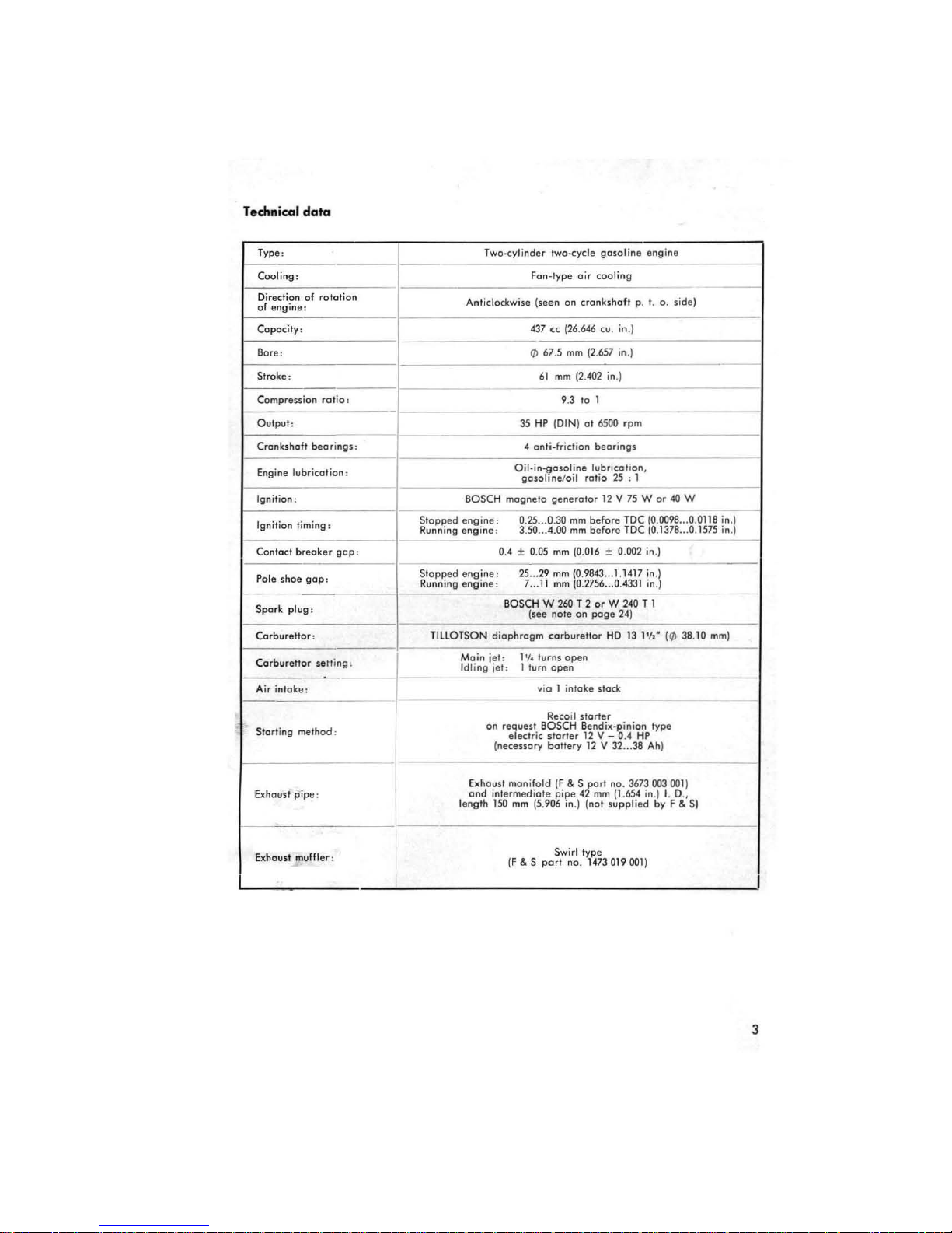
Technical
data
Type:
Cooling :
Direclion of rololion
of
engine
:
Copocily:
Bore :
Strake:
Compress ion
Oulput :
Cronkshoft beo rings : 4 on li-friclion
Eng
ine lubricot ion :
Ignition :
Ignition timi
Contocl
Pole shoe
Spork plug:
Corburetlor
Corb
Air inlok
Storling m
breoker
urellor
e:
ratio
: 9.3 10 1
ng:
gop
:
sett
elhod
gop
: 0.4 ± 0.
:
ina .
,
Siopped
Runn
Siopped
Running engin
TlllOTSON
Tw
o-cylinde r Iwo-cycle
Anliclockwise
Oil.in.gasoline
mognelo
BOSCH
engine
ing
:
engine
:
engine:
e:
BOSCH
diophrogm
Moin jel: 1'1. lurns
Idl
ing jet : 1 lurn
on
request BOSCH Bendix-pinion type
elect r
(necessory
Fon-Iype
oir coolil1g
(seen on cronkshofl p.
43
7 ce (26.
(/)
67.5 mm (2.
mm
(2.402 in
61
35
HP
(OIN)
gosoline
/oil
generolor
0.25 ... 0.
30
3.
25
mm
50
.. .4
.00
mm
05
mm
(0.0
...
29
mm
\0.
11
mm
7 ...
(see note on
0.2756 ...
W260T2
corburellor
open
open
via 1 inloke stock
Recoil slo r
ic
storler
bollery
gosoline
646
cu. in
657 in.)
.)
01
6500
beoring
lubri
cotion
ratio
25
12 V 75
bef
ore TDC
before
16
± 0
9843
... 1.1417 in'l
0.4331 in.
orW240
poge
HO
ler
12 V - 0.4
12
V 32 ...
engi ne
I. o. side)
.)
rpm
s
,
: 1
W or 40 W
!O.0098
TDC 0.1378
.002 in.)
T 1
24)
131'
/1-
HP
38 Ah)
---
... 0.0118 in'l
... 0.
(0 38.10
---
---
---
1575 in.
mm
--
---
)
--
bhoust
pipe:
Exhousl muffler :
Exhousl moni
ond inlerm
150
lenglh
fo
ld (F & S
ediole
pipe
mm
(5.906 in.) (nol
Swirl
(F & S
part no. 1473019001)
pari
42
type
mm
no.
supplie
3673
(1.654 in.)
d by F & S)
003
001)
L C.,
I
3
Page 8

REPAIR
TOOLS AND ASSEMBL Y
~
tj
5
6
~
11
,8
Ä
~
1
7,8
2
JIG
n
~17.9
3
7
4
~
~
9
8
4
21
18
12
10
~
13
~
14
r:ri
15
11
16
C1i
17
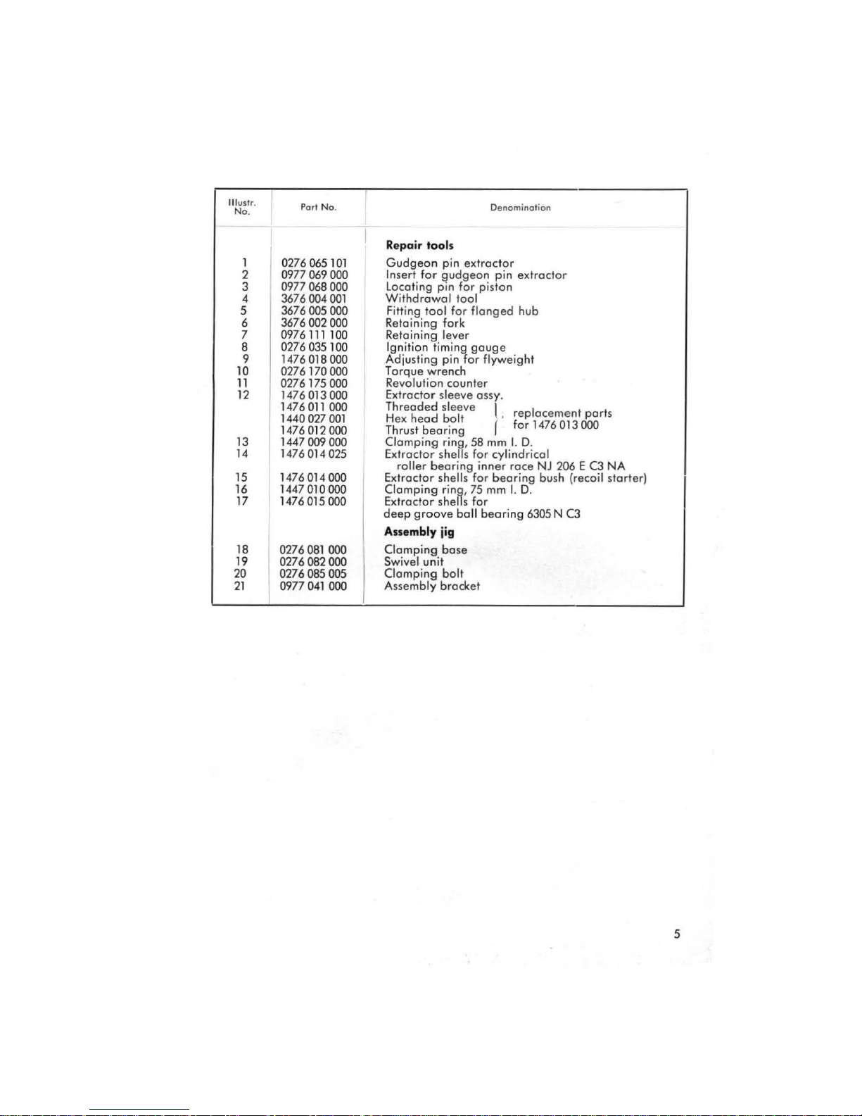
Page 9
IlIuslr.
No
.
1
2
3 0977
Porl
0276065
0977
069
068
No.
4 3676004001
5 3676005000
3676002000
6
0976
7
111
8 0276035100
9 1476018000
10
11
12
0276170000
0276175000
14
76013000
1476011000
1440027001
14
760
13
14
15
16
120
1447009000
1476014025
1476014000
144701 0
17 1476015000
18
19
20
21
0276081000
0276082000
0276085005
0977
041
101
000
000
100
00
000
000
I
Repair
.oolt
Gudgeon pin extroclor
In
ser
t for gudgeon pin extroctor
locoti
ng
WithdrowoJ
Fitting tool for flonged hub
Retaining fork
Retoining lever
Ignition timi ng gauge
Adju
T orque wrench
Revolution counter
Extroctor sleeve
Threoded sleeve
H
ex
Thrust
Clomping
Extroctor
Extroctor
Clompi
Extractor
deep
pin for piston
1001
sting
pin for flyweight
ossy.
head bolt . replocement ports
beorin g for
ring,
58
roller beoring inner roce NJ
shells for cylindricol
shells
ring,
sh
ells
for bearing
75
for
ng
groove ball beari ng
Ass.mbly jig
Clomping ba
Swivel unit
se
Clamping ball
Assemb
ly brocket
Denomination
f
1476
mm
I.
D.
mm
I.
D.
6305 N C3
013 000
206 E C3
bush
(recoil starter)
NA
5
Page 10

DISMANTLING
THE ENGINE
Detach
all
contral
cables
between
engine
ond
frame
.
$crew
off
cover
(wit
h inscription SACHS) .
Pul1
ignition
leads
with
rubber
boots
out
of
the
recesses
ond
remove
cover.
Disconnect
electrical
wir
ing
bet
ween engi
ne
end
frame
cf
the
terminals
(2
end
3,
F
ig.42).
Remove
exhaust
muffler,
exhoust
tube
end
manifold
.
Remove
the
engine
end
clean
it
thoroughly
be
fore
toking
it
aport.
When
giving
the
engine 0 general
overhaul,
components
should
be
dismounted
in
the
seque
nce
ind
icated
.
f ig. l
Fig. 2
6
I"take stack, carburettor
and recoil starter
Fig. l
Mount engine
on
asse
mbly
i
i~
(repair tools
no. 18, 19, 20 ond 21)
with 2 hex
head
bolts M
'0 x 30
,
os
shown
in
the ill
ustration
.
Sc
rew
off intoke
stack
(5)
wit h
rei
nforcement
ring
(4)
.
Pull
off
impulse pipe
(2)
.
Remove
carburettor
(3)
(ta king
co
re
of
insulati ng sl
eeves
a nd
go,ket).
Unscrew
rec
oi l
starte
r
(1)
to-
gether
with inser
ted laby
rinth
ring.
V-pulle
ys
and V-belt
Fig. 2
Use retoining
fork
\3,
repoir
too
l
no
. 6)
to hold
the
id
er
pulley half
(l),
os
shown
in
the
illust
ratio
n.
Unscrew
nut
and
remove
idle
r
pulley
half
(taking
ca
re
of
wosh-
ers).
Unscrew
pulley
(4)
and
remo
ve
it
together
with
V-belt
(5).
Remo
ve
secand
idler
pulley half
together
with
washers.
Remove
Woodruff
key from
fan
shaft
(2).
Page 11
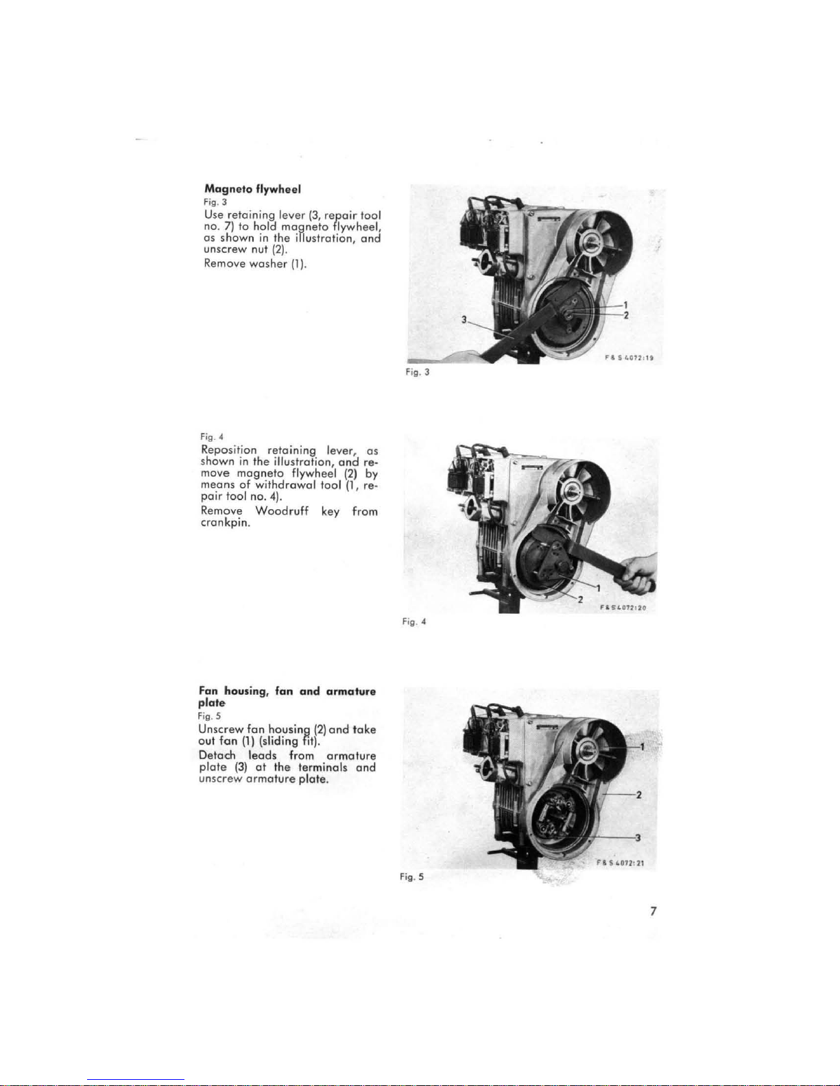
Magneto
Fig. 3
Use
no
os
unscrew
Remove
Fig. 4
Repos itio n
shown
retaining
.
7)
10
hold
shown
nut
washer
in
the illustration,
flywheel
lever
magneto
in
Ihe
(2).
(1)
retaining
(3,
repo;r
illustration,
.
lever,
move mogneto Ilywheel
means
cf
pair
tao
Remo
ve
crankpin
withdrowol
I no. 4
).
Woodruff
.
tao
key
tao
flywheel ,
end
os
end
re·
(2)
by
I (1, re-
from
I
Fan housing, fan
plote
Fig. 5
Unscrew
out
Detoch
plote
uns
Ion
(3)
crew
fan
housing
(1)
(sliding lit).
leads
ot
the
ormature
end
(2)
fram
terminals
plote
armature
end
take
ormoture
ond
.
Fig. 4
Fig
. S
7
Page 12
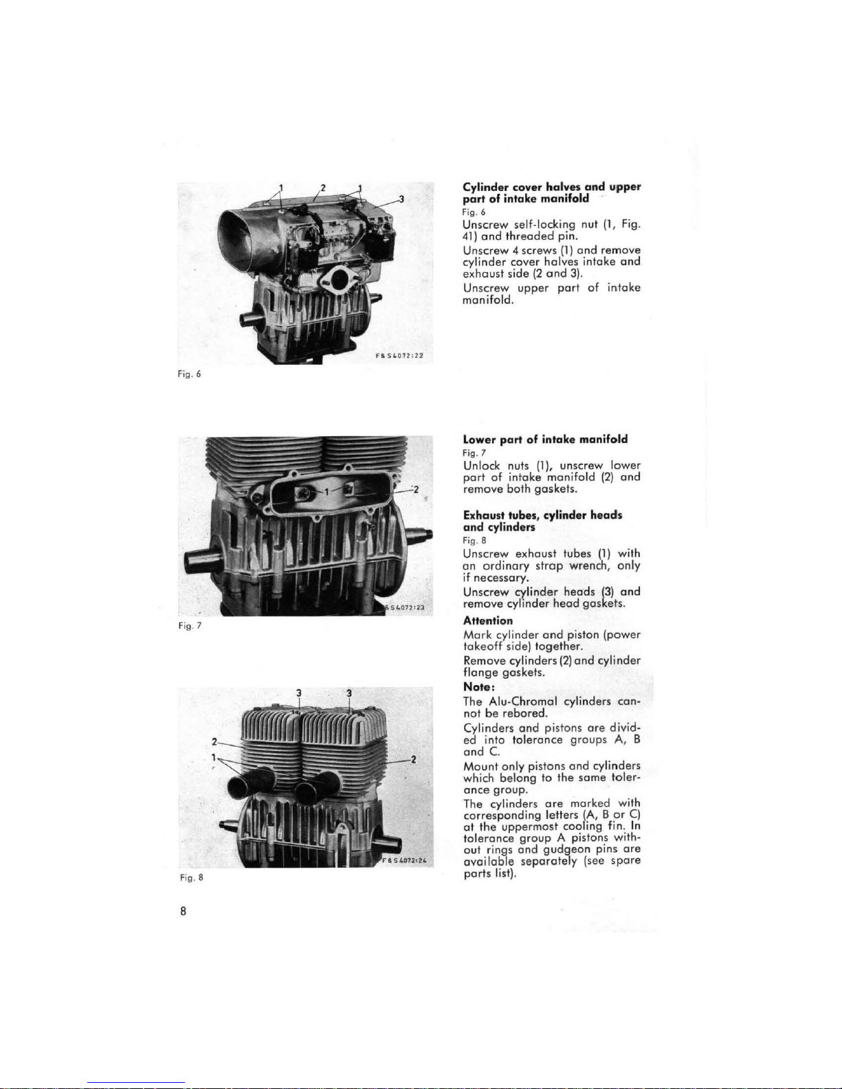
Fig. 6
Fi
g.7
Fi
g.8
8
Cylinder cover halves
and
upper
part
of
intake manifold
Fig
. 6
Unscrew self-Iocking nut (1,
Fig
.
41)
end
threoded
pin.
Unscrew 4 serews
(1)
ond
remove
eylinder cover hclves intoke ond
exhaust
side
(2
ond 3).
Unscrew
upper
port
of
inloke
monifold.
Lower
part
of
intake
manifold
F
ig.7
Unloek nuts (1), unscrew lower
port of intoke monifold
(2)
and
remove both gaskets.
Exhaust tubes, cylinder
heads
and
cylinders
Fi
g.8
Unscrew exhoust tubes
(1)
with
on
ordinory
strap
wrench, only
if
neeessory.
Un
serew eylinder
heeds
(3)
end
remove eylinder heod ge skets.
AHention
Mark
ey
linder
ond
piston (power
lakeoff
side)
tagether.
Remove eylinder s
(2)
end
eylinder
flonge
gasket
s.
Note
:
The
Alu-Chromel cylinders eon-
not
be
rebored
.
eylinders
end
pistons
are
divid-
ed
info to l
erance
groups A, B
and
C.
M
ount
only pistons
and
eylinders
which belong
10 the
same
toler
-
enee
group.
The eylinders
are
morked wit h
eorresponding letters
(A, B or
Cl
01
Ih
e uppermosl eooling fin. In
toleronee
group
A pistons with-
out rings
end
gudgeon
pins
are
ovailable
separately
(see
spore
parts list)
,
Page 13
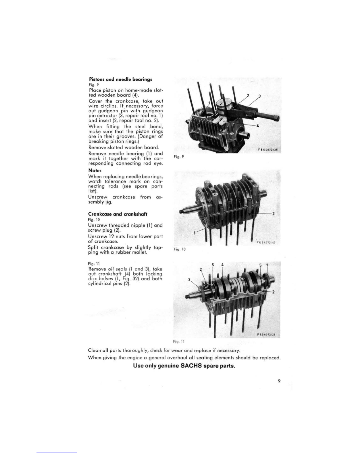
Pistons
and
ne
edle
Fig. 9
Piece piston
led
wooden
on
home-mode
board
(41.
Cover the cronkcose,
bearing
wire circlips.
out
gudgeon
pin extroctor
ond
insert
When
make sure
ore
in
If
necessory, force
pin with
(3,
repair
(2,
repOlr
fitting the steel bond,
thot
their
the piston rings
grooves
s
slol-
toke
out
gudgeon
tao
I no. 1)
tao I no. 2).
. (Donger of
breoking piston rings.)
Remove
Remave
mark
it
,slotted
needle
taget
wooden
bearing
her
with
board
(1)
the
.
and
cor- F
responding connecting rod eye.
Note
:
When
replocing
wolch toleronce mark
necting rads (see
needle
spore
bearings,
on
con-
pari
lisll·
Unscrew crankcose from as-
sembly
jig.
ig
. 9
s
Crankcase
Fig. 10
Unscrew
screw plug
Unscrew 12 nuts from lower
and
crankshaft
Ihreaded
(21.
nipple
(11
ond
part
of crankcose.
Split crank.case by slightly top- Fig.
ping with 0
F
ig.1
Remove ail seals
out
disc halves (
cylindricol pins
Clean
When
rubber
mallet.
1
(1
and
3), take
cronkshaft (4) both locking
1,
Fi~
.
321
ond
bolh
(2).
oll ports thorough
giving the
ly,
check for
engine a general
Use
only
genuine
Fig.
weor
overhoul oll sealing elements should be reploced.
10
11
and
reploce
SACHS
if
necessory.
spare parts.
F&
S40U'1I
9
Page 14

WORK
ON
INDIVIDUAL
COMPONENTS
Replacing
Of
Ihe cronkshoft
end
Ihe cylindrical roller
Removal
Fig.
12
Remove
(
1)
01
Remove
(7)
by
sleeve (3,
cf
outer race
beoring
inner
meons
repoir
crankshaft
inner roc
.
of
Remove shims
bearings
beorings
(4)
race
(1)
suitabl e
tools no . 12, 13, 14, 15, 16
{Bl
.
only Ihe
bearing
es
cf
cf
cylindricol roller bearing end roller eoge from inner
of
cylindricol roll
edrector
on the
cylindricol roller
shells (5
deep
er
groo
power
bearings
bearing
end
ond 17)
ve ball
tokeoff s
end
--4
ond
6),
clamping
.
beoring
ide
can
deep groove
the
deep
rings
on Ihe
be
replaced
groove
(2)
mogneto
.
ball
bearing
Fe S 4072:
ball
bear
ond
extroctor
side
s.
27
roc::e
ing
A"ention
If
shims
have
cylindricol roller
10
been
domoged
bearing, reploce
dur
ing the
Ihem by
operation
new
ones
cf
removing Ihe inner
.
race
of
Ihe
Page 15
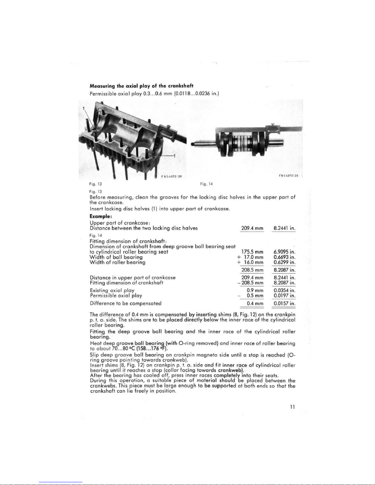
Measurin9
Perm issib
.he
le axi
axial
play
al
ploy 0.3 ... 0.6
of
.he
cra
nks
haf.
mm
(0.0118 ... 0.0236 in.)
Fig. 13 Fig.
Fig. 13
Before meosuri ng,
the
crankcose
In
sert
locking disc halves
clean
the grooves for
the
locking disc halves
.
(1)
into
upper
port
of
Example:
Upper
port
of
Distonce
Fig.
14
Fitting dimensio n
Dimension
to cylindrical
Widlh
Width
Distance
Fitting dimension
Existing axial
Perm
issi
Difference
The
difference
p. t. o.
roller
bearing.
Fitting
beari
ng.
H
eot
deep
10
aboul
Slip d
eep
ring
9roo
In
sert
shims (8, Fig. 12) on
beoring
After the
During this
cronkwebs. This
crcnkshaft
cronkcose:
between
01
ball
of
roller
in
the two locking disc halves
of
of
cronkshaft
crankshaft
roller
bearing
fram
bearing
bearing
upper
port
of
of
cronkcose
cronkshoft
ploy
ble aXial
side
the
70 ... 80 'e (158 ... 176 'F) .
ve pointing
unlil
bearing
play
to
be
compensoted
of
0.4
. The shims
deep
9roove
9roove
9roove
it
reache
ball
ball
has
operation
piece
mm
is
are
bearing
bearing
towards
s 0 s
cooled
, a suitable pie
must
con lie freely in position.
:
deep
groove
seat
compensated
to
be
placed
ball
bearing
(wilh
on
cronkp
cronkweb).
crankpin
fop
be
(collor
off
, press
lorge e
p. t.
by
directly
and
0-rin9
o.
facing
inner
ce
of
nough
in
ball
inserting shims
the
removed)
mogneto
side
towards
roces
material
10
14
cronkcose
bearing
below
the
inner
ond inner
side
and
fit
cronkweb).
completely
should
be
supported
.
seat
inner
race
unlil a
inner
209.4
175
+ 17.0
+ 16.0
- 208.5
(8,
Fig. 12)
of
ro
be
ct
in
the
upper port
mm
.5
mm
mm
mm
208.5
mm
209.4
mm
mm
0.
9mm
0.
5mm
OAmm
on
roce
the
roce
ce
into
ploced
.he
of
the cylindrical
cylindrical roller
of
roller
stop
is
of
cylindrical roller
the
ir seafs.
between
bolh ends
8.2441
6.9095
0.6693
0.6299
8.2087
8.
2441
8.2087
0.0354 in.
0.0197
0.0157
crankp
bearing
reached
so
thot
of
in
in
in
in
in
in
in
in
in.
(0 -
the
the
.
.
.
.
.
.
.
.
in
11
Page 16
Never
clamp
the
the
crankshoft
inner
roces
by
unserviceoble
Piece
auter
(groove
Wel
bearings
for
O-rings (5, Fig. 11) slightly with oil
.
hommering
. •
race
cf
O-rin~
facing
in
cylindricol
towords
0 vise
ol:a
cronkpin
. This will crush
roller
bearing
cronkweb)
end
the
with
.
insert
or
of
the
webs
roller
them into
webs,
end
cage
ond
render
onlo
the
auter
never
Iry
the
cronkshoft
the inner
roces
of
10
ra
fit
ce
the
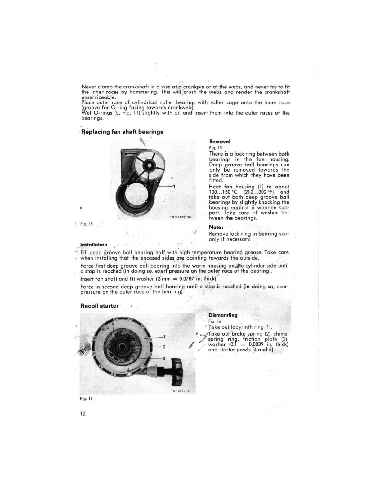
~eplacing
. Fig.
15
fan
shaft
bearings
) Mtallation . .
:. F-
i11
deep
.
when
Force first
a
stop
Insert
F
orce
pressure
Recoil
gtöove
instolling thot
is
reoched
fan
in second
on
starter
deep
shaft
the
ball
groove
(in
and
fit
deep
outer
bearing
the
encosed
ball
doing
washer
groove
roce
half
with"hi
sides
~
so,
of
bearin
ball
the
\ \
.g into
exert
press
(2
~
mm = 0.0787 in. thick)
beoring
beoring
\Ji!P
"'"
ure
).
gh
the
Removal
Fig.
1S
There
is
bearings
Deep
groove
only
be
side
from which they nove
fitted .
Heat
fon housing (
100
...
150'( (212 ...
take
out
beerings
housing
port. Take
tween
the
Note :
't
' Remove lock ring
only if
necessary
temperature
pointing
warm
on
the
until 0
stop
towords
houslng
outer
race
:-
.,
•• s
reac~ed
bearing
onJite
Dismantling
Fig.
16
,
Take
out
•
,~e~
7
/ /
",
out
s'p
flng ring, fricti
wosher (0.1 ~ 0.0039 in. thick)
and
starter
0 lock
ri
n9
the
boll
between
fon
housing.
bearings
towords
1)
10
in
remov.ed
302'F)
balh
deep
groove
by slightlY knocking
ogoinst 0 wooden
core
of wosher
beorings
.
in
bearing
.
grease
cylinder
bearing).
(in
doing
. Take
.
side
so, exerl
the
of
outside
the
...
laby~inth
brake spr
pawls
ring
ing
on
(4
and 5).
(1)
.
(2). shim,
plate
baln
can
the
been
cbaut
end
ball
the
sup·
be·
seat
car
until
(3),
e
.
Fig.
16
12
""s
«171
: J1
Page 17

Fig. 17
Pull
out
cm
(19
horne-mode
os
show"
clamping
{51
.
clomping
.
clomping
handle
(4)
from
rope
retoining
rope
ro
sterter
in.1
taper
pe
50
with
(2)
,
Take
clomping
hondle
Withdraw
from
rope
Remove
ter
(SI, ,top
(9)
Remove
starter
Remove
necessory.
Carefully
coil
coil
Toke
Remave
Fig. 18
Reise
toke
spring, toking
spring
jump
core
of
rope
spring
spring.
Hold
coil
thumbs
roising
o~
Note
Replece
necessary
shells,
spring
(see
eoch
oltl!ro.0te sides .
;
bush (1, Fig .
, using the
clampin~
tractor slee ve
15
, 13
ond
121
Take
ca
re
bush {I, Fig .
of
ro
ond
hold
retaining
in
the
illustration.
ring
out
clomping
ring
ring
with
Hanged
ond
f10nged
.
clip
run
back
guide
out
care
out
.
disc
{3,
from
pulley
end
10
toke
firmly
illustrotion)
thumb,
let
ring
(repair
.
toleronce
201
.
pe
opprox
pulley
clip
(6)
with
of
starter
taper
end
detoch
end
star-
sleeve
sleeve
ond
completely.
(3) only
pulley
with
not
10
Fig. 19
1.
.
out
coil
with
both
end,
out
spring
201
only
extroctor
and
ex-
tools no.
ring
(11
(7)
let
if
let
by
if
in
.
FI541111
' 32
Fi
g.
17
Assembly
Fig
. 19
B
efore
assembling,
with
Aero-SHEll-Grease
fi
l/
the
4 lubricating
the pul/ey with
cont
.
Insert coil spring, os shown in
illustration, with
in
stud
(1)
anti-clockwi
Ensure
flat
, fitting coil by co.!
se
direction .
that
ond
the ccil spring lies
even.
grease
grooves
~he
.same lubri-
end
of
spring
14
and
in
sprin~
(2)
in
Fig.
19
f 1 !o4071;
lI
Page 18

Fig.
20
r&5""012,)",,
Fig.
21
F
'~40
72'
JI
F
ig.22
Fig. 20
Before inserting pulley, stick
wasller
(3,
Fig
. 19, 0.8
mm
thick
= 0.032
in.)
with 0 little
grease
into recess
of
pulley.
Fit
pulley
onto
bearing
pin
ond
insert
end
of
spring
(4,
Fig
.
19
)
ot
stud (2).
Tension pulley/ coil sp ring
in
storting direction until 0 s
top
is
encountered.
Release coil s
pring
appr
ox.
112
•.•
1 turn until tlle recess for the sol·
dered
nipple
in
the pulley rests
near
the
rope
passage
of the
housing.
Hold pulley with
home-made
retoining
clIP
(2,
Fig.
21)
.
Pull
the
starter rope
through
a
rag
moistened with
SAE
1 0 oil be-
fore
assemb
ling.
Fig.
21
Fit
rope
guide
(3,
if
removed),
lIonged
sleeve (B),stop (4),lIonged
sleeve
(7),
starter
handle
(5)
ond
clamping
ring
(6
)
onto
Ihe
rope
.
(Iamp
rope
guide
with
filI
ister
heod
cop
screw
(9)
M 4 x
10
.
lay
starter
rope
around
clomp-
ing
taper
and
pull
it
into
clamp
-
ing ring .
Pull
clamping ring into s
tarter
handle
and
let
sta
rter
rope
run
back.
Fig. 22
lubricate
starter
pawl
bed
and
starter powls ligMly with
SAE
10
oil.
~
Fit
star
ter
powls
(4
ond
5)
.
The open
side
of
the
starter
pawl
seati ng
and
the long side
of
the
s
tarter
pawl face
in
storting di-
rection.
F
it
was
her 0.1
mm
(0
.0039
in
.)
thick, friction
plote
(3),
spring
ring and shims os required .
Insert
broke
ring
(2)
.
Insert labyrinth ring
(1)
.
After
"'ounting
the
bra
ke
spr
ing, the friction
plate
should have
an
<llöillElil,
ay
of
0.1 ... 0.2
mm
(0.0039
... 0.0079
in
.).
CQ,rrect this play by inserting shims
under
the
broke
spring .
Page 19

Magneto
generator
The cyli
Fig.
1 = Sei
2 =
3 =
4 = Ign
S = Sei
6 =
7 = Armolure
8 = l ubricoling wiek
9 =
nder
23
of
conlocl
(apacito
tgnition
ilion
of
conlocl points
(apacitor
Generator
on
points
r
armolure
arme/ure
plole
ormalure
the
p. t. o. si
I
10'
cylinder
I
'0'
cylinder
de
of
the
cronkshaft
2
1
Fig.
23
is referred
Replacing the ignit ion or generator armatur.
Open
up
the
strop
ormoture
Generator
are lothe-turned ond con be mounted 10 the armeture plote
Ploce new
(toke
After
t
ween armoture
is
oblained
ond
ormature
core
cf
installation
ground
only
.
ignition
it
p,0les
1I
Ine
Screw
holding
off
armeture
in
position
wire
is
necessary
and
gap
the
armoture
, os
on
generator
flywheel,
is
0.
25
ore
shown
under
... 0.
35
which
is
to
avoiloble
armature
all circum s
becau
mm
os
in
the
illustration,
J.
tance
se maximum ignition
(0.0098
... 0.
be reploc
spore
s 10
0138
Note:
Far
corr
ect
meo
rectly on ils
sureme nt
bearings
ond
adjustment
it
is
necessary
that
.
10 os cylinder 1.
ed
ond
unsold
ports
. The
without
ond
mea
in
.).
the
armoture
special equipment.
screw it
sure
the
and
lighting
crankshaft
air
er
on
gap
rests
leads
poles
Iightly
be·
power
cor·
.
Fig.24
Air
gap
0
.25
in
... 0.35
.).
is mea
0.
0138
The
gap
places, through
flywheel.
If
the
gap
is
slightly
the
armeture
ened
adjustment
the
apertures
odjusted
the
fastening
can
not
mm
(0.
sured
in several
the sials
correct,
it
by repositioning
ofter
having sleck-
sc rews. The
be
made
in
the flywhee
through
0098
in
can
l.
...
the
be
Fig.
24
15
Page 20

Replacing
In
order
ploce both sets
The
are
are
1.
2. Remove r
3. Unscrew
4. Unscrew pivot
New
Coulk
Use only the set s
When fitted
Apply
Smeer
slider. (BOSCH
Da
Replacing the
1. Unsolder
2.
3. Remave th e
4.
5. Sold
the
sets
10
cchieve
contoet
badly worn, if
damoged
Screw
not
off
parts
the
BaSCH
BOSCH
allow
breoker
.
primory
eloiner
filiister
should
piv
ot
in position,
Ft 1 v 8
greose
any
capacitor
sh
the
t new
er
bot
leads
capacitor
copacitor
h l
Pu
In
ser
of
shoft
greose
caulked
01
eontad
0 uniform i9nition setting
contoet points
should
the
ond
head
shoft
be
fitted
after
of
contact
grease
.
eads
points
together
be
beoring
lead
from
greo
Ft
is a v
out
spots
to their terminals.
reploced
bush
end
copacitor lead
contoet
cop screw
the
1 v 4
or
ond
brecker
armeture
in
reverse
screwing
points spec
contact bre
se 10
bear
on
ailable in
oil
to
of
the
armature
from the
carefully caulk
is
end
il in.
the lubricating
reach
.
if
the
worn
cr
arm
remo
plote.
ord
er,
ified
for
aker
ing bush
tubes at
the
contacts
plote
hole
with a sc
agoin
for
both
contocts,
if
the contoet
.
from pivot
ve
contoct carrier.
proceeding
th.s
engine
points must
before
fitting .
pad
ond
all
BaSCH
.
with a
rape
.
cylinder
round
.s
the
slider
brecker
shaft
(take
os fellows :
.
not
be
on
the
suppliers.)
piece
r.
il
is
necessory
or
the pivot
arm
care
displaced
greose
of
wood
cr
the
of
shims) .
or
wedge
.
10
re·
shoft
spring
tilted.
in
the
Replacing ignition coils and ignition leads with
Removal
F
Unscrew ignition coil
linder
2).
Remove
cab
ni
Installation
~crew
Ilon cods.
Pl
wi
cabl.
(
tion coils.
Scr
ground
cap
w
tion .
Attention
When
replac
ing
spark
the
spring
tagether
16
in
cantael
plug termina ls,
gels
with the ignition
with the
lead
into the
hang
core
of the ignitio.n
spark
spring into ignition
plug terminal.
spark
plug terminals
ig.
2S
1)
end
coble
le
shoes
tian
leads
!gnition l
ac.
cabl. ,ho.,
re
(brown)
,hae,
blue) on
asher
terminal 1
ew
on
wire using 3 filIister
screws M 5 x
s, as shown
lead
),
(5
,
coil
(4
shaes
(2)
and unscrew
(1)
.
eads
on
terminal
(3) far
ignition coils with
lead
(make s
and
insert the
for
, for cylinder
(3
)
(11
to igni·
(2)
far
graund
15
pri
mary le
of
the igni.
and
the
head
spring
illustr
ure
spr
25
in
cy·
and
ig·
and
ad
a·
thot
ing
Page 21

Replacing
the
flanged
hub
, the
magneto
flywheel
and
the cam
fig.26
Slocken
4 Phillips
screws
(l)
in
mogneto
flywheel
(5)
by
light
iorring
blows,
screw
them
out
ond
rem
ave
the
flanged
hub.
Unscrew
retaining
ring
(3)
end
take
out
cam
(4).
Fill
onnular
groove
(8)
with
BOSCH
greose
Ft
1 v 26
ond
slightly
greose
cam
support
in
flywheel.
(BOSCH
greose
is
ovailable
in
tubes
01
oll BOSCH
suppliers.)
Insert cam (4).
fit
retaining
ring
{3} ond
fasten
with 3 filiister
heod
cop
screws M 4 x 5
ond
woshers. Fig. 26
Toke
lock
ring
(7),
flyweight (6)
ond
thrust
washer
below
off
from
bearing
pin.
Greose
bearing
pin
ond
bearing
surface
of
flyweight
in
flywheel
slightly
with BOSCH
greose
Ft
1
v 26.
Fit
thrust
washer
(0.3
mm
=
0.0118
in
. thick)
on
bearing
pin,
insert spring
(2)
in
flyweight.
Fit
flyweight
on
bearing
pin
(must
engage
with cam)
end
se·
eure
with
lock
ring
(7).
Cam
end
flyweight
must
olwoys
be
freemoving.
Position
flonged
hub
on
the
mogneto
flywheel
(5) in sueh 0
woy
thot
the
bores
coin
-
eide.
Degr
ease
4 eonvex
-heod
Phillips
screws
M 6 x 10
with 0 suitoble
solvent
(we
re-
co
mmend
Tri),
lute
with LOCTITE AA-89-790
ond
screw
them
in.
Tightening
torque
0.9
...
1.1
kpm
(6.5 ... 8.0 ft. Ib.).
17
Page 22

Ca
rburettor
The type
of
therefore
No
av
the
gine
rich. Repeated
carburettor
When
thermal
or
lure
Special
os when
parts
be
Only
mum
Adjusti
Wnen
carburettor
mounta
open
of
ccrburettor,
tests in the
not
alteration
er
quietly
throttle
is
pounds
end
the
carburettor
volue
w~t
plugs
IS
too
lean.
ca
re
the
fuel
of
the
sufficient 10
0 correctly
of
economicol
ng
the car
using
setting will
inous
ing.
foctory
. T
advisoble
of
the
ond
or
carburettor
smoothly
opened,
end
runs unevenly,
spitting
or
difficult storting
is
is
used,
indicote
should
the insulotor
rich mixture,
be
taken
feed
is
restricted insufficient lubricont will
engine. With
provide
odjusted
operation.
bureHo
the
engine
oreas)
, the supply
the
iet sizes
he
setting ochieved in this
10
alter
ond
it.
setting
01
lew ,speed
gives
ifs
full
or
caugh
if
ing, bockfiring with 0 blue flame
are
correctly
odjusted
of
wnereas
to
ensure
a two-stroke
odequote
lubricotion .
corburettor
r for spe ci
at
be
oltitudes
required.
of
al
above
fuel should
Starting
On
Tillotson
diophragm
corburettors
itself .
The choke serves to facilitate storting.
cold
engine.
When
o rieher fuelloir mixlure
be
slowly
Tillotson
The
phrogms
2
pump diophragms
On 0 warm
the
choke is
opened
diaphro~m
: a
contral dlophragm
closed
.
engine
, 0
is
obtoined. Once
corburettor
for
drawing
it shou ld
higher
for
the
vocuum
the
iet
odjustment
way
should
be
(i. e.
when
output
01
the
exhaust
indications
full revs without
fumes
that
ond 0 suitable
the
spark
plug
a wnite
that
the
carburettor
engine
wil l
climatic
the
ensure low
condition
1000 metres (3280 ft.
In
places
where
be
restri
the
choke
is
II
should
be
be
c!osed only partiolly,
is
coused
the
engine
can
function
proFo
rtioning the fuel feed
fue from
the
tank
are
is
mode
idling),
are
determined
an
opimum
os
lang
occelerates
black,
the mixture
spark
snould
be
insulator
brown
indicates
setting
be
carburettor
conveyed
setting should olwoys
fue l consumption
s
density
by
changi
),
air
cted
incorporoted
fully
closed
in
the
mixing
hos
started
in
ony
position a nd hos 3
.
by
volue,
ond
os
the
engine
steodily
caughing. If
the
mixture is
stobbing
is
tao
lean
from the
.
plug with a
in
color. Sooty
thai
the
is never
0
correc
to
and
too
the
on opti·
tion
is reduced (i. e .
ng
the
main jet
in
the
corburettor
only
for
storting
if
ever.
chamber,
, Ihe choke
to
the
engine ond
m
eons
it
turns
when
the en·
tao
correct
mix·
low,
moving
of
the
in
the
so
thot
should
dia·
is
18
Page 23

TILLOTSON-Diaphragm Carburettor (Schematic view)
FiR.27
Hose nipple
10A
Idling oullel possoge
2.
Inlel
compression
spring
2 Fuel
pump
body
lOB
By-poss
possoge
21
In1el conlrol l
eve
r
3
Fuel
pump
diophrogm
11
Butterfly volve
22
Pi
vot pin
3A
Inlel vorve
on
pump
12
Moin jet orifice
23
Venl hole
diophrogm
13
Corburetlar
hausing
24
Diophrogm housing
38
Oullel
valve
on
pump
14
Throol of
carburellor
(venturi!
25
D
iaphrogm
diaph
ragm
IS
Moin fueJ
autlel
2.
Air
chambar
,
Fuel
pump
gaskel
16
Choke
27 Filter
gosket
5 Di
ophragm
housing
gasket
17
FueJ
passage
!rom
pump
28
Fuel
strainer
6 Conlrol
chamber
10 conlrol chomber
29
Filter housing sc re w
7
Ad
justing screw for idJing jet
J8
Inlet
needle
ond
seol
3.
Fuel
chamber
8
Impulse
possoge
18A
(opper
seal
31
Pulsation
chamber
9 Idling jet orifice
19
Adjusli
ng
screw for moin iet
32
Fuel
'iller
ho using
19
Page 24

Carburettor
The Tillol50n
odjustoble
ing
points
1.
Ta
odjust
should
2.
With
odiustoble iet
leon (see also
3. The
odjusting
closedl, 0,5 th
Initi
al
adjustment
Fig.
28
adjustment
ccrburettor
jets. If
engine
should
be
the
be
thoroughly
screws
is
is
troubles
borne
corbureltor
warmed up.
s,
care
poge 18).
for
will
deform
the
first
carburettor
occur
in
mind:
correctly
should
be
the jets must
the
seato
F&SL072;31
ond
used
the
jets
for maxi mum
token
not
never
be
screwed
have
10
on
SACHS
10
output
render
tao
be
readiu
(full
the
fight
engines
load),
fuel/oir mixt
sted ,
into
which
the
the
the seat
has
follow-
engine
ure
tao
(i.
e.
Fig.
29
Far ini
tial
ediu
.29)
the
.
odiustment,
screw
). Then
sting
screw
so
fer
bock
sc r
ew
for
in
ogein
adjusting
is
encauntered
the
Fig
turn
open
F
inel adjustment: see
20
close the
the
turn
af
thet
sectio
idling
the
t~e
.
1I
IS
ebout
n HTe
odjusting
iet
(3, Fig . 29) (turn in
odiusting
idling
jet
langer
one
o~e
who
no
st.running
screw
turn
In
contect
le
screw
far
.
Tur~
turn, so
the
engine"
for
the
clockwise
the
mein
the
wlth
the
thel
main
idling
Ihe
on
iet
(1,
Filii'
direction
iet
bock
egoin
odjustment screw
butterfly
butterfly
pege
velve leve
velve
40.
28)
end
Idl 0 light
1'
/.
r;
is slightly
the
stap
turns
then
,
(1,
Page 25

Mointenance
0'
the
carburettor
At
certoin
intervals every
corburettor
must be disassembled,
cleoned
ond
overhouled.
All
exterio
r dirt should
be
cleon
ed
off with
gaso
line
before
disossembly. The bores,
ducts, possoges
end
jets must not
be
cleoned wifh hord object.s
(e.
g. wire
or
drill),
but should only
be rinsed with
gasoline
end
cleoned
with compressed
air
(remave
diophragms
before
blowing through). Before ossembly, check thaI oll
carburettor
components (especia
lly jet
seals
ond
diophragms)
are
in
proper
working
order.
Cnecking
ond
c1eaning
the
fuel
filter
in
good
time
he lps 10
ochieve 0 sotisfoctory
per-
formance of
the
carburettor
ond langer
engine service life.
Special
maintenance
instructions
1.
If
the pump feil
s,
alwoys check (before removing the
pump
diophrogm) the
im-
pulse
pipe
for
leokage
or
blockoge.
2.
When
fitting the inlet control lever
and the
comp
ression spri ng (see illustration
),
make sure
that
both
ends
of the spring
are
embedded
in
the
spring seats.
Fig. 30
3. The compression spring
mus!
not
be
stretched,
os
the spring
tension
is
accurately
adiusted
to the carburettor.
4.
The inlel control lever
is
cor-
rectly
inserted when
it
is
at
'he
same
level os the bottom
of !he
diaphragm
chamber
(see
arrows
on illustration).
5. The inlet needle should close
iu
s!
when
the inlel control le-
ver
is
flush with the bottom of
the chomber. If
this
is
not the
case, odiust the
lever by
bending
it
0 little (on the
in
-
let ne
edle
side
).
6.
When assembling the corburettor, moke sure thot
dia-
phragms, gasket
and
cast-
ira n
part
s of the housing
are
carefully inser
ted
into !he
cast-on centering pinsi
simi-
larly,
the gaskets, the pump
diaphragms end
the fuel
pump
body
are
eligned
by
means of the
same
kind of
centering pin
s.
The
diophragm
gaskets
are
always positioned on that
side
of
the
diaphragm
wh
ich
foces
towards
the
carburettor
housing.
21
Page 26

Decarbonizing
In
every
two-strake.engine
the
200
with
Fig,
engine 0 portion
eylinders
hours
of
correct
31
corburettor
end
operation,
the
exhaust
is
deposited
in
the exhoust system. T
01 the lotest when engine performance
setting, the engine lends
of
muffle
the
lubricoting
chiefly
ra,s,4
r,
the
cylinders
oil
on
is
the
piston crowns,
he
carbon should be removed
10
011:
40
burnt
and the
ond
cylinder_heads
farms
carben
in
the exhoust ports of
drops
four-strake.
Exhoust system
Fig.
31
Detach
tube end monifold.
Clean the inside of the
with
The
exhoust
on
ordinory
exhoust
muffler,
wire
muffler
dismontled for cleaning.
Carben
by
h
cr
eot
in 0
heoting
deposits
by meons
farge
the
fire
cf
.
con
muffler 10
0 we lding
which
after
cr
when, even
•
manifold
brush.
cannot
be
burnt off
every
ex
in 0
haust
be
red
forch
The exhaust system sho uld not be modified, as
mental to
Any modifications of the
punishable offen
I
:..
Cylinder
Unscrew the cylinder heods
combustion chambers with a
performance
head.
and fuel consumption
exhaust
ce
.
and
remove t
scre
wdrive r. Take
comb ustion chambers.
Cylinder ports
Place piston
Rem
ove
Clean exhoust tubes with on
Corefully
ot
carbon
place
and
exhaust
bottom
deposits
piston
dead
in
01
top
tubes
center
exhaust
ordinary
dead
.
center
Pistons
Corefully remove only the thicker
not try 10
scrope
the piston crowns
carbon
10
any
such a lterations will
and
will increase the exhoust noise.
moreover
illegal
deposits from the inside
care
not to
damage
ports with a screwdriver.
and
system
he
transfer
are
carbon
wire brush.
and
remove loose
carbon
.
deposits (flakes) from the piston crown.
a bright metallic condition .
be
and
constitute a
the surface
detri·
of
of
s.
the
the
Do
22
Page 27

ASSEMBLING
THE
ENGINE
Crankcase and crankshaft
Fig.
32
Screw
threoded
nipple
(4)
end
convex·head filiister
heod
cop
screw
(3)
M 6 x 6
with
gasket
into
upper
part
of
crankcose.
Note:
Before
inserting
the
locking disc
ha
lves,
cleon
both
grooves
in
the
upper
part
of
the
cronkcase.
Insert both
loo.in9
disc
holve
s
(1)
and
bath
eylindrieal
pins
12)
.
Fig.
33
Insert
preossembled
crankshoft
into
upper
port
of
cronkcose,
deep
groove
ball bearing
(2)
fac -
ing towords
magneto
side.
Fill
the grooves of the oil
sea
ls
with
hii:lh
temperoture
bearing
grease
Alvenie
3)
befere
fitting
Ihern. A
so
smeor
the
seoling
lips
slightly
with tllis
grease.
Fit oil
seal
13,23.6
x 62 x 10)
on
crankpin
magneto
side,
end
oil
seal (1, 28.4 x 62 x 10)
on
eronk-
pin p. t. o.
side,
flush with Ihe
outer
edge
of
Ihe cronkcose.
(
Sealing
lips focing
towords
cronkweb.)
Smear
sealing
surfaces
in
cronk·
case
with
sealing
compound
(we
recommend
sealing
compound
No.
1073
supplied
by
Mssr·s.
Ernst
Sonderhoff,
D-50oo
Köln-Biek-
dorf
, Postfach 22).
F
ig.3
4
Put
on
lower
part
of
crankco
se
~).
Screw
cronkcase
holves
together
with 12 nuts M 8
and
spring
was
her
s.
The
nuts
have
to
be
tiQhtened
diogonolly
(beginning
wlth
the
nuts in
the
middle).
Tightening
torque
2.3 ... 2.8 kpm
116.6
... 20.211. Ib.
).
Mount
cronkcose
on o5lsembly
Fig.
32
Fig.
33
jig, os
shown
in Fig. 9. Fig.
34
"S40U
,"1
23
Page 28

Fig.
35
Fig.
36
Attention
When
.screwing
Spork plug W 2
' po
rk
plug W 260 T 2 for eylin
in
the
spark
40
T 1 for eylind
Needle
Fig.
Insert
the
needle
sponding
bearings and pistons
35
both needle
illustrotion sho
beor
eonneeting rod eyes,
oilin9 them slightly
tion
~see
ing
der
GINE"
morking of needle beor-
ond eonn
"DISMANTLING T
on
poge
Put pistons on Ihe conneeting
rads with
tao
I no. 3
),
poi nt ing t
arro
owords
side.
Attention
Fit
morked piston on connecting
rod p.
t. o.
eylinder
under
GINE" on
and piston p. t. o. side
"DISMANTLING
poge 8).
Use a slotted
F
it Ihe
gudgeon
If
neeessary, heot piston to
70
...
80'(
by
troctor
in
sert
emave
R
Cov
4 wire
Cyl
exhaust tub
Fi
g.36
(158
meen
s of the
(3, repoir
(2,
repair
the loeating pin.
er
the cronkcose
ci
rcl
ips.
inders, "ylinder heads and
es
Fit cylinder
cording
to Ihe s
fer ports .
Ploce piston s
boord
(4,
Fig
linders which should be slightly
oiled
before Ihis
morked cylinder
the p.
I. o. ,ide).
Re
mave
Fit
sheet
eyl
F
passages
slotted
cylinder head gaskets (small
meta I
inder
heod
it
cylinder heods (spark plug
focing towards miet
,ide).
plugs walch the length of the threcds .
er
heod
with
oppro
x.
13
mm
(D.
der
heod with opprox. 17
mm
(0.
51
67 in.)
-
bearings (1
ws
ing) into the
ee ting rod
only
before
eorre
inser·
eye
HE
9).
loeoling pin (
repoir
ws on piston tops
the exnoust
si
de (see merking of
THE
wooden
board
pin (sliding fit).
..
.176'F) ond
gudgeon
pin ex·
tool no. 1)
1001 no . 2).
ond
insert
flange
.
hope
on
35
goskets
of the trans-
slott
ed
)
ond
fit
woo
the
operation
is
to
be
filted on
wooden
rim
focing t
board.
owords
).
in.) threod length,
threod length.
one
un-
EN-
EN-
(4)
fit
end
ce·
den
ey-
(the
,
·
.
it
24
Page 29

for
aligning
the cylinder, sc
rew
in
exhoust
tubes (4)
provisianally,
fit
exhaust
mani
-.
fo
ld
(3)
temporori
ly
ond move
the pistons
up
end
down
severol
times
:"
F
asten cyl
inders
end
cylinder
head
s with 4 nuts
(l)
M 8
and
4 nuts
(2)
M 8 x
27
and
weshers
(3.5
mm
:;:;;
0.134 in. thick
).
Tighten
the
nuts
diag
onally.
T;ghten;ng
torque
2.8 ... 3.0 kpm (20.2 ... 22.011. Ib.).
Remove exh
aust
manifold
.
Tighten
exhaust
tube
s with
an
ordinory
strop
wrench.
Lower
and
upper
part
of
intake
manifold
Fig.
37
Fit
both
gaskets
on
the cylinders
end
fasten lower
part
of
intoke
mon;fold
(2)
w;th 4 nuts M
6,
2 spring
woshers
ond
the
two
lock;ng
plotes (1).
Send
the
locking
plotes
over
.
F
asten
upper
part
of
intake
ma-
nifold with
sea
ling ring
inserted
,
with 6
filIister
heod
cop
screws
M 6 x
30
and
spring
woshers.
Carburettor
and
intake stack
F
ig.37
Fit
gaskets
end
both
insul
ating
sleeves
on
upper
part
of
intake
manifold
and
fasten
carburettor
with
two
self-Iocking nuts M
8.
T;ghten; ng
torque
0.8 ...
1.1
kpm (5.8 ... 8.0
ft.
Ib.
).
Fit impulse
pipe
to
nipple
(4,
Fig. 32)
and
carburettor
connection
(2, Fig. 29).
Fasten
intake
stock
(5,
Fig.
1)
and
reinforcement
ring
(4,
Fig. 1) with 3 filIister
heod
cop
screws
'I, "
ond
spring
woshers.
Armature
plote
,
Fig.
38
Insert
armoture
plate
(3)
tagether
with
leads.
Watch
the
morkings
(2). A new
ormature
plote
hos
no
morking
and
can
be al
igned
by
meons
of
the
longitudinal
slots.
Sme
or
both
filiister
head
cop
s
crew
s
(1
) M 5 x
15
with wa.shers
with
sealing
compa
und (we re-
commend
the liquid
sea
lin
,9.
com-
pound "Diamant" type
OW
H,
supplied
by
Messrs .
Glöckne
r
KG,
D-8756 Kohl/Mo;n, Postfach
80)
and
tighten
them.
Ti
ghtening
torque
0.4 ... 0.5 kpm fig.
38
(2.9
... 3.611. Ib.).
25
Page 30

F
ig.39
Fig.
40
Fig.
41
26
Fan houf ing
Fig.
3'9
.. p
Pl
ace
insu
loting sheolh
(5,
Fig.38)
with wires into
Ihe
passage
(4,
Fig.38).
Ploce fan housing
(1)
into cen-
tering
device
on
cronkcase and
fasten
it
with 4 hex
heod
screws
(2)
M 8 x 25.
Tightening torque 1
.5
. . 2.0 kpm
(10
.8
... 14.411. lb.)
Cylinder covers
F
ig.40
Fasten cylinder cover exhaust
and intoke side
(l
and
5)
10
the
fon housing
(3)
wilh 2 fillisler
head
cap
screws
(4)
M 6 x 30 ond
1
filIister head
cop
screw
(2)
M 6
x
75
with spring
was
hers (moke
sure that the covers are
propedy
seoled).
Tightening
lorque
for filIister
heod
screw
M 6 x 30 0.5 ... 0.6 kpm
(3.6 .. .4.3
11. Ib
.)
Tightening torque for filIister
head
cap
screw M 6 x
75
1
.5
..
2.0 kpm (10.8 ... 14.4 11. Ib.)
Fig.
41
Screw both cylinder cover ho lves
logelher
wilh
Ihreoded
ball
(2)
M 6 x 182 (Iocked
wi
lh 2 nuls M
6)
end 1 se
lf-Iocking nul
(1)
M 6
ond
washers.
Fasten both
cylinder cover halves
to the cylinder
heads
with 4 con-
vex-heod
filIister head
cap
screws
(3)
M 8 x 15 and spring
washers.
Page 31

Fig.42
lead
insulating
wires
towards
connect
Terminal
lighting
10
Terminal
Primory
10 terminal 1
Primory
10
Ground
10 termi"
Magne
Insert
Attention
If
terminal
leod
terminal
nal
to
Woodruff
new
contaet
os
block
leods
block
leod
wire
flywhe
~(lth-
the:
folIows:
2:
(yellow)
1
end
3:
(blue
(blue)
2
(brown)
3
el
key
breokers
(11
termine 5 ond
with
2
/yellow)
into
crankpin
hove
been
0.4 ± 0.05 mm (0.01575 ± 0.00196
neto
flywheel
grealest
Degreose
Fit
mogneto
occurately
retaining
Use
washer
with
erankpin
Tightening
in
distonce
the
taper
flywheel
with
lever to
end
toper).
torque
such Q
from
the
cf
.he
with
the
groove
hold
nut M 14 x 1
11.0
... 12.0 kpm (79.6
way
thot
cronkpin
crankshaft
flonged
in
the
the
.
fitted
in.)
,
the sliders
.
hub,
flanged
mogneto
.5
(the
Fig.
42
or
odiust
end
cf
ma
king
hub.
flywheel , os
ehamfered
...
86.8 ft. Ib.).
if
'he
contoet
cf
the
the
mogneto
sure
side
contoe'
breokers
contaet
that
shown
of
breoker
before
breoker
flywheel.
the
Woodruff
in
Fig. 4,
the
wosher
gap
fitting
arms
faeing
is
key
and
not
within
'he
hove
engages
fasten
towards
mag·
'he
it
Ignition
Fig.
Firing
Stopped
0.25
before
Running
3.5
before
Contaet
timing
43
point
:
engine
...
0.30 mm (0.0098
TDC
engine
...
4.0 mm (0.1378
TDC
breaker
gap
0.4 ± 0.05 mm
(0.01575 ± 0.00196
Pole
shoe
Stopped
gop'
engine
25 ... 29 mm (0.9843
Running
7
...
Measuring
Ignitian
Feeler
The
"
O-l-M"
·0"
top
"M" indieates
engine
11
mm (0.2756
instruments:
timing
gouge
flanged
0.4 mm (0.016 in.)
hub
is
for
eoineides with
dead
center
the
gouge
is
piston 1 (p. t. o. side), "
.
firing
...
0.0118 in.)
...
0.1575 in.)
:
in
...
1.1417 in.)
...
0.4331 in.) ' ;9.
(repair
tool no . 8),
provided
the
with two
morking
position
.)
(1,
.
punched
O-M" is
Fig.
43
adjusting
mark
for
43)
on
the
pin for
s.
pisto
n
fon
housing
flyweight
2.
when
(repair
the
tool no.
piston
9)
.
is
ot
27
Page 32

It
is
advisable
since
engine
also
be
performance
coused
Also check the
Measurin9 out
If there
10 be meosured
gouge
Fig.
Fig. 45
are
no timing marks
ond
the
44
10 check
the
depends
byon
incorrect
electrode
and
out
adjusting
gap
determining timing
ond
determined
pin,
ignition setting
on
it
. Vorious
ignition setting .
01
the
spark
marks
on
the
flanged
in
occording
operating
10
5.
6. Determine TDC
every
time
when
the
in
the
lighting system
020
in
fan
by
meons cf
45
(1,
engine
.).
housing,
:
fon
Fig.
plug
hub
the
troubles
(0.5
mm
ond
position
following
Fig. «
, . Provide the
= 0.
on
the
description
end
o
mark
2. Move piston 1 (p. t. o. sideJ
with timing
10
top
position
10
that
In
this
Ilywheel,
hub
with
os
shown
Tiahten
44)
until 0 light
gauge
dead
center, ond
cf
mogneto
piston position.
position
provide
the
in
Fi~
adiustmg
countered.
3.
When
adiusting
vonce,
mi
soges
of
bearing
nd
300
it
that
are
towards
surfaces
has
Ihe
inclined
Therefore 0 correspondingly
value
has
to
be
Fig.
45,
300
ample
Ex
II
the
liring
0.1575
...
value
to
(0.1575
... 0.
rurn
odiusting
clockwise
va
lue 10
iusting nut = 1
Pul flyweighl in
4.
position, using
weight
Fig.
Turn
recti o n
nut
(3)
In
pro
mark
shawn
piston 2
Ilanged
7. Take
retai
46)
.
mogneto
(2,
Fig.
and
piston
thi,s
position
vide the
"M"
in Fi
out
ning pin.
or
of
in
hub
:
in
be
odopted, os
scole
(A)
.
point
is
belore
adopted
in
.) (scoie A).
3.5
TDC
.)
be
1811
nut (2, Fig.
direction, according
adiusted
mm)
(1 turn
.
campletely
adiustlng
retoining pin (os shown
flywheel
rotatio
n, until the
44)
rests
on
the
of
the
magneto
hub
with
the
ond
firing position
way,
pin
the
meosuring pin
and
1 hits
flonged
end
g.
43.
the
same
with "0 "
adjusting
is
serviced,
moy
they
hove
the
timing
housing
43)
.
(3
with
, Fig.
olign
flywheel
cf
the
mogneto
the
to
.
the
43.
stap
be
mark
nut
spark
borne
plug
01
an
Ilanged
"0 ",
(2,
Fig
is
en·
od·
pas·
angle
TDC
spark
the piston
.
higher
shown
... 4.0 mm
(scale
(0.137
C),
the
is 4.0 .. .4.6 mm
44)
in
anti·
10 the
of
the ad·
releo
for
its di·
sed
fly·
pln
ogainst
adiusling
timing
gauge
(1).
flywheel
with
the
timing
mark
""",
and
mar
k the
"M".
(3,
Fig. 46)
44)
.
in
in
8
In
os
af
or
28
Page 33

The ignition
setting
completely releosed.
When
the
cam
1.
er
5, Fig. 23) for
is
2. Bring flyweight
Fig.
46
Lift flywe i
adiusting pi"
into
the
the
weight
position
No
If there
ing pin, inse
ing
= 0.
hole
completely
00
tao
the
neta
3. Turn
ght
(11
(3,
the
bore
chomfered
in such 0
side
flyweight,
in
complefely
.
te:
is
no bore
rt
pi"
08
(21
0 sui
(round pin,
in.
dia
.) into the
ond
bring flyweight
released
not
inser
deep
ormoture coils
flywheel
mcrk
t the
becouse it may d
is
the
mogneto
"O -l -M"
sli~htly,
repolr
ond
far
when
turned.
on
housing.
4. Turn the
(
5, Fig.
corrected
tudinal
Turni
turning
After
5.
-
Diamant
Tight
Tighten
Tightening
6.
If
be
magneto flywheel sli
23)
for
by
turning
slots.
ng
the
armature
it in
direction
any
such
" (
see
ening
torque
magneto
torque
the
ign ition se tt ing
7 ...
11
mm (0.2776 ... 0.4
cylinder 1 should
is
carried
01
its
cylinder
in
operating
out
highest position,
1 (p. t. o.
position.
inse rt
tool no.
faces
bring
way
that
towords
fly·
releas ed
9)
the odiust -
toble
retoin-
approx
. 2 mm
tapped
in
position .
retaining
the
omog
the
mag
flywheel
flanged
pi"
e
-
ogcinst
hub
ghtly
the
armature
plate
cgainsl
of
rotation
correction, smear
pcge
25)
and
tighten
0.4 ... 0.5 kpm (2.9
flywheel nut.
11.0
...
12.0 kpm (79.6 ... 86.8
is ccrried o ut correctly,
331
in.)
in
operating
odiust
,ide)
to
0.4 ± 0.
Fig.
46
its
direction
c;:oincides with the
in
direction
now
begin
10
plate. This can
the
directian
retards
the
armcture
plote
them.
...
3.6
ft
.
Ib
.
position
contoet
05
of
of
open. If
be
of
ignition.
screws with s
.1
ft
.
Ib
.1
the
pole
, i. e. wnen
breoker
tbe
flyweight
gap
(contoct break-
mm (0.016 ± 0.002 in.).
rotation
rotation: the
done
rotation
mark
not,
the
by
until the "MN
(1,
Fig. 43)
contoct
firing
point
means
of
advances
Ihe ignition,
ecling
shoe
gap
(0,
Fig.
of
the
on
the
fan
brecker
can
be
the
longi-
compound
47)
should
is
Fig.47
The
pole
where
leaves
s
hoe
the
shoe
the
magnet
the
edge
of
the ignition
direction
megneto flywheel.
Shou
ld
the
correct
slightly
breoker
of
0.4 ± 0.05 mm (0.016 ± 0.002
pole shoe
,
it
can
adjusting
gap
gap
of
of
rotation
be
(b) with
is
meosured
in
the
flywheel
the
crmcture
armature,
gap
corrected
the
in
the
in
of
the
be in-
by
contact
ran
ge
in
.).
F
ig.47
29
Page 34

7. Turn
mogneto
flywheel
against
its
direction
of
rotation
until
the "M"
of
the
mark
"
O-M"
on
the
flonged
hub
coincides
with
the
mark
(1, Fig.
43)
on
the
fon
housing.
8.
Turn
the
mogneto
flywheel
slightly
in
direction
of
rotation: the
canteet
breaker
(1,
Fig. 23)
far
cylinder 2 should
now
begin
to
open.
If
not, the
firing
poinfcan
be
corrected
by
odiusting the
canteet
breaker
gap
within the
range
of
DA
± 0.05
mm
(0.016 ± 0.002 in.l .
9. Remove adjusting
pin
(3,
Fig.
46)
or
retoining pin.
Fig.
48
30
V-pulleys
and
V-belt
Fi
g.48
Insert
Woodruff
key
into
fan
,hatt
\1
\
and
li\
one
idler
pu\le~
hall
(31
.
Ploce V-bell
(41
9
.5
x 650 on pul-
ley
(51
ond
lasten
pulley with 3
filIister
heod
cop
screws
M 6 x 15
end
spring
washers.
Tightening
torque 0.8
...
1.1
kpm
(5.8
...
8.011
.
Ib.l.
Insert
shims
(2)
os
required
(they
serve
Jo
odjust
the
tension
of
the
V·beltl ·
Fig.
49
Fit
se(ond
idler pulley hall
111
.
Use
retoining
fork
{2J,
as
shown
in
the
illustration,
and
tighten
nut
M 14 x 1.5
together
with
spring
washer
.
Tightening
torque
4.0 . .4.5
kpm
(28.9
...
32.5
If.
Ib.l.
Check
V-bell
tension
.
Note
:
If
one
presses
ogainst
the
V-bell
wi
th
one
's
thumb
, it
should
yield
opprox.
1.5 cm (0.6 inJ.
The
cor-
reet
tension
is
achieve
by
toking
out
or
inserting
shims
between
the
two
pulley
holves.
Tension
is
increased
by
tokina
oul
shims,
and
diminished
by
mserting
ad-
ditional
shims.
Ne
wly
fitted
V-beil
s h
ave 0 tend-
ency
10 s
tretch. They should
be
checked
aft
er
opprox.
20
hours
af
operation, and
retightened
if
necessary
.
Page 35

Recoil
starter
Fig.
50
Fasten recoil
starter
byrinth ring inserted,
housing with two
cop
screws (1) M 6 x 38
lister
heod
ond
cop
spring woshers, os shown
filIister heod
screw
the illustration.
(2),
with la-
10 Ihe fon
ond
1 fil-
(3)
M 6 x 52
in
Fig
.50
Electrical
After instolling the
Connections
engine,
restore the electrical wires from
terminals.
Fasten cover (wilh inscription SACHS) 10 cylinder
heod
cop
leads
into the recesses
screws M 6 x
of
38
end
the
spring
cover.
weshers,
cover
end
frame
10
engine
half intoke side with 5 filiister
place
rubber
boots with ignition
10
their
31
Page 36

ENGINE WITH BOSCH BENDIX-PINION
TYPE
ELECTRIC STARTER (Type DG)
The BOSCH
Bendix-pinion
is
an
electric, manuolly
opera
ted
cranking
motor
with
Ben -
dix
drive
ond
overrunning
roller
dulch.
The
energy
necessory for
operating
the
starter
is
taken
from 0 12 V bottery with 0
capacity
01
32
...
38
Ah.
How
the start
er
works
The
pinien
with
overrunning
roller
dulch
is
mounted
on 0 coarse
screw
thread
on
the
storter spindie.
In
rest position
the
pinion
is
held bock
end
out
of
engagement
by
spring tension .
When
the
storter
is
switched
on,
end
the
motor
begins 10 spi n,
the
weight
of
the
pinion
causes
it
10
be
left
momentarily
cf 0 standstill,
so
that
it
runs 010°9
the
spind
ie
ond
en909es
with the ring
geer
teeth
, thus
providing
0 positive drive
for
cranking
the
engine
. As
500n
os
the
engine start
s, the pinion
is
driven by the
engine, at a speed
greater
thon
that
of
the
motor spindie. When
the
starter
switch
is
releosed
, the pinion
is
spun back
olong
the screwed spindie,
assisted
by spring tension ,
is
put
out
of
engagem
ent
and
returns to rest position.
The overrunning
roller clutch prevents
premature
pinian
disengagement
.
Removal
Fig.
51
Un
screw s
tarter {ll,
flange
(2)
and
starter
ring
gear
(3).
Note
:
II
the
teeth
01
the ring
gear
(3)
ere
damaged
, check
the
teeth
01
the s
tarter
pinion. If necessory,
replace ring
gear
and
pinion.
Fig.
52
Screw with
drawa
l tool
(1, repair
tool no . 4)
onto
the hub (2) with
3 filIister
head
cop
screws
M 6 x
75
os
shown
in
the illustration.
Place intermedi
ate
plate (approx
.
5
mm
= 0
.2
in. thick) between
extractor
screw
and
crankpin
and
rem
ove
hub
.
Note
:
When
dismantl i
ng
the
engine
completely, wotch oil
seal
p. t. o.
side (dimension
45
x 62 x 8).
32
Fig.
51
Fig.
52
Page 37

Installation
Fig.
53
Put hub
(1)
ond
slee
ve
12)
on
crankpin.
Serew bolt
pin unlil 0
(3)
with nut into eronk·
stop
is
eneountered.
Foree the hub on by tightening
the
nut
(4),
until 0
stop
is
en·
eountered. Unserew installation
equipment.
Fig.
53
Fit
starter
ring ge
ar
(3,
Fig. 51) by fastening
it
with 6 he
with spring washers. Tighten the serews diagonolly.
flange
(2,
Serew
Screw
starter
eore
to ensure eorreet posi
Apply
and
starter pin io n
(l,
graphite
Fig. 51)
grease (e. g. BOSeH
Fig. 51)
(1,
Fig
onto
the eronkeo se with 2 nuts M 8
onto the flonge with 2 nuts M
tion
of
eonnecting terminal.
grease
Ft
1 v
. 51).
13)
to starter
xagon head
and
8and
serews M 6 x 10
spring washers .
spr ings washers. Take
ring
gear
(3,
Fig. 51)
Operation,
maintenance
Operation
Da not leave
the
Before switching on
to
reeover.
proee
If
the
s
tar
ter before e ngine
geer
If
the
only
obove
Maintananca
Work
strong
work
If
there
ss. Release the s
equi pm
ent
will
be
damaged
eng ine
does
to the exhaustion of
oll the fuel feed).
on
the electric port of the
ly
reco mmended to detoch the
of
this kind. Da not lay
and
lubrication
starter
switehed on for more thon
again
, woit 1 minute to allow
is
is 0 da
not
shing
tarter
switch os
provided
or
pinion have
of
with 0
.
not
start after
the
several
battery
starter
10015
on the
01
the
electric
10
seeonds without
the start
er to cool
teeth, switch off immediotely
soon
os the
engine runs
starter
eome
ottempts, it
safety
10
0 standstill.
is
. Try to loeote the trouble
under
deviee, da
Otherwise
useless 10 try
end
may involve short cireuit
ground
lead from the
battery
.
bottery
starter
interruption.
and
the
and
repeat
its
own
power.
not switch on the
pinion
and
aga in. This
eliminote it (check
s.
Therefore
before
doing
bottery
the
ring
leads
it
any
33
is
Page 38

Carbon brushes
The
carbon
brushes
should
be
checked from time 10 time.
After
unscrewing
the
cover
end
removing the
reteiner,
the
shims
end
the
cover, proceed
os fellows:
reise
the
spring
that
presses
the
carbon
brush
onto
the
commutotor
with 0
suitoble
hook
(take
ca
re not
10
bend
the
spring
sidewoys
ond
da
not
reise
it
more
thon
necessory
);
then
check
whether
the
carben
brushes con
be
moved
easily
within
their
guides
in
the
brush
holder
.
The
carben
brushes
ond
the
brush
holder
must
be
free
cf
dust
, oil
ond
greose.
If
these
parts
are
fouled
or
iommed, cleon
them
with 0
clean
cloth
that has
been
moistened
with
gasoline (da
not
use
cotton
wes
te
becau
se
it
fuzzes
tao
easily)
end
dry
them weil.
Ne
ver touch
the
fa
ces
cf
the
carben
brushes wi th
emery
paper
, files
or
knives. B
low
the brush
holder
thoroughly
clean.
If 0 earbon
brush
is
broken, has
become
unsolder-
ed
or
is warn to suc h
an
extent
that
the
spring
or
the
strand
of
wire
soldered
into the
brush
threatens
to
contaet
the
brush
holder, replace
it.
(Use only BOSCH
earbon
brushes.)
When
fitting
the
carbon
brushes
moke
sure
that
the spring
does
not hit
the
brush.
When
fitti ng
the
cover, make
sure
thot
the
armature
shoft
end
the
ermature
itself
are
seoted
properly
in
the
housing
and
that
the
carbon
brushes
rest
on
the
commutoto
r.
Fit
shims
end
retainer
ond
fast
en
the
cover
.
When
giving the
engine 0 general
overha
ul
it
is
edvisable
to
replace
the
carbon
brushes.
Commutator
The
surfoce
of
the
commutetor should
be
uniformly
smooth end
grayish
block
in
color
.
Furthermore
it
should
be
free
of
dust,
oil
ond
greose.
Fouled
eommutotors
should
be
cleaned
with 0
clean
cloth
thot hos
been
mois
tened
with gas
oline
(do
not
use
cotton
w
oste
);
dry weil
after
cleaning. Commutotors that
hove
become
scored
or
worn
out
of
round
should
be
turned
down
on 0 lathe
in 0 workshop
equipped
for
this
purpose.
By
no
meons should 0 commutator
be
to uch
ed
with 0 file
or
with
emery
paper
.
Lubrication
lubrieote
the
starter only with s
uiteble
lubricont
s.
Adhere
10
the
instructions of .he
manufacturer
(BOSCH
).
From time
10
time
the
pinion
and .he ring
geor
shou
ld
be
cleaned
with 0 brush
that
hos
been
dipped
in
gasoline, and
greased wi.h
graphite
greose (e. g. BOSCH
Ft
1 v 13).
This
wi
ll
prolong
their
service life.
34
Page 39

Starter faults
If
starter
faults
lie with
grounding
shooting
A.
When
the
armature
1. Bottery
occur
the
starter
points
hints
are
.he
starter
shaft
dischorged
but
restricted
is
does
,
2. Bettery leulty,
3. BeHery
bad
4.
Starter
terminals loose, oxidized,
ground connection,
terminals
or
grounded,
5.
Carben
!ie
in
foul
6.
Starter
on
their
ed
brushes
the
commutator,
guides,
or
dirty,
switch
cf
starter
are
domog
(Ieese perls),
7. Voltcge lass
domoged, lead
B.
When
the
armature
engine
does
in
leads
.he starter
shaft
not
start:
connections
is
rotates
I. Bottery insufliciently
2. Press ure
sufficient,
3.
Voltage
of
carbon bru
lass
in lead.s
it
hos
10
itself
nar
that
the fuel feed
10
swi
tch
ed on ,
not
rotate
brushes
da
are
worn,
jommed
broken
ed
too
great,
100se.
switched on,
, but
the
cho'ged
shes
not
tao
great.
be
borne
octuol
in
mayaiso
starter
with 0 foulty
the
:
not
,
leads
,
mind
that
electricol
be
system.
C. Armature
does
not
1. Pi
nion
2.
Burr
D. Pinion fails
engine
Pinion
1.
or
damaged;
2.
Starter
does
tained
(sus
their
cause
connection
involved
. The
shaft
engage
dirty,
on
pinion
to
has s
tarted
or
ring
spring
switch (reloy)
not
interrupt
contact).
must
cf
following
rotate
:
or
ring
disengage
:
geer
teeth
weak
or
the
not
necessorily
the
s,
bu.
gear.
after
very
or
starter
circuit
vehicle's
troub
le-
pinion
dirty
broken
button
,
35
Page 40

INSTRUCTIONS
FOR
AND
The
of
necessory lighting system
the
connecting up 0 rectifier
The
nominal output.
If
tamps
part
they
lasses
blocks .
(are
the chassis to
The following
MAGNETO GENERATOR
12V
magneto
40
cr
lighting
lamps
in
the
cose
ond
no. 3665008000).
have
in
long
should
AI
lighting
A,
Res
istonce
system wilh
811 = Ign
C
C. = Generalor
Co
C, = Jgnilion coils (externol)
C
CII = Primary lead
ition/light/slort switch
= Mogneto
= Jgnition ormolures (primo
..
= Spork plugs
Cu = Terminal blocks
C
.. = lighting
.. = Ground
C
C" = Shorl·circuit leods
C
..
= Primary
75W
generator
75
W respectively.
leads
(yellow); the
should
compensote
the
be
Otherwise
of
the 75 W
necessary
leads
, use wires
also
be
the
lomps.
are
the symbols used in
lood
(12
V
(12 V 35
40
W light )
generotor
ormature
leods (yellow)
wire (brown)
cylinder 1 (blue)
lead
cylinder 2 (blue/yellow)
so
the
When
token
40
W, for
s
AND
produces
curren'
WIRING DIAGRAM
olternotin~
If
an
engine
is
token from
second
if
0
bottery
selected
the
is
that
lamps
equipment
difference
replacing
minimum cross
of
1.0
mmJ cross section
to
ensure 0 good
W)
75
W
ry)
12
turrent
15
opera
only
connection
used (see wiring
the
magneto
may
burn
out
.
the full
by
connecting
wires
sectian
the
wiring
load
of
af
the
af
0.75 mm
ground
diogram
1
15
31
= Short·circuit leod connection
31b = Short-circuit leod conneclion
50
= Connection remoins blind
53 = light
530 = Connecli
53c =
o = Off (ignition short-circuited)
I = Hight
11
= Doylight dri
111 = El
V 40 W
of
12 V with 0 lighting
ted without eleclric
one
of
'he
remoins blind
diagram
generator
75 W
0 resistor 35 W in
magneta
1
for
connections
connection
on
Terminols:
on
Igniti
Pr
imary le
Ground connection
Ignitionllightlst
ing leod connection
Generator
Switch positions:
dri
eclric stort {
two connections
on
poge
is
loaded
is
not
reoched, take
generator, ensure
In
order
.
from the
poge 37.
coils:
ad
connecrian
ort
switch:
on
remoins blind
lood conneclion
.....
ing
.....
ing
pro
..... idedl
end
parallel
to
ovoid
at
power
starter
serves for
39)
.
10 its full
40 W
(F
valtoge
the
terminal
engine
.he
of
& S
that
via
36
Page 41

1
11=1
I
'I~H
~
~::~
--""":A
ro
/ I
cr
1
.
I
.J
I
.
I
•
L..--
L.
.........
l
.
t---1,
•
I
r+----l
._._.J
.
37
Page 42

INSTRUCTIONS
AND
WIRING DIAGRAM
FOR
MAGNETO GENERATOR
12 V 75
W
AND
BOSCH BENDIX-PINI
ON
TYPE
ELECTRIC STARTER
(Type DG)
The magneto
generator
produces alternoting
current
of
12
V with 0 lighting powe
r
0175 W.
The
two
yellow
lightinß leads
are
connected to the
rectifier
for
charging 0 12 V
32
...
38
Ah
bottery for hghting
end
eledric starter
operation
(see wiring
diagram on
poge
39
).
During
dayl
ight
driving
only
1 circuit
is
connected up, in
order
10 ovoid overchar ging
of
the
bettery;
during
night
driv
ing, both
circuits
are
connected up.
The
lomps should
be
so selected
that
the total load is 50 W .
When
replocing wires in the mog n
eto
generator,
ensure
that
they hove the necessory
minimum
cross
section
of
0.75 mm
1
.
In
order
10
ovoid voltage
lasses
in
lang
lead
s,
wires of 1.0
mm1 cross section should
be
used
for
connections
at
the terminal block
s.
For
battery
and
starter
connection use the following wire cross sections:
16
mm1 if the
length
of
the
lead
is
less thon 1 m,
ond
25
mm1 if
the
length of
the
lead
is
more thon
1 m.
Care
should
also
be
taken
to
ensure a good
ground
connection from the engine via
the chassis to the
lamp
s.
The followi ng
are
the symbols u
sed
in the wiring
diagram
on
poge 39.
AI = load
(12
V 50
W)
Bn = I
gnition/
ligh
tlsta
rt switch
C =
Magnelo
generator
Cl =
Generator
OrmOh.H
8S
C. = Ignition
armatures (primary
)
C. = tg n
it
ion coils (exte
rna
l)
CII =
Spark
plugs
Cu = Bal
tery
(12 V 32
...
3B
Ah)
Cu
= Rectifie r
Cu = Terminal
blocks
Cu
= l i
ghling
leads
(ye
l1o
w)
CII =
Ground
wire (
brown)
C" = Short·circuit
leods
Cu = Primary
lead cylind
er
1 (blue)
CI' =
Primary
lead
cyli
nder
2 (blue!y el1ow)
E = Electric
starte
r
E. = Starter
relay
S = F
uses
(4
Amps)
Termi
nCl
I. :
I
gnitian coils:
=
Pr
imary
lead
connection
15 = Graund
wire
connection
38
I
gnil
ionllighlllf
Clrt
.wit
d!:
31 = S
hart
·circuit
lead
conneclion
31
b = Short-circuit
lead
conneclion
50
= Conlrol
lead (sta rt
er
reloy)
and
lighting
lead
con nection (d. c.)
53 = Conneclio
n:
battery
+
53 = lighting lead conneclion
(d. c
.)
53c =
Connection:
load (12
V
50
W)
R
eetifi.,:
51
lighting lead
connection
(0. c.)
53
lighling
leo d
connection
(d. c.)
Starter ...
ICl
Y:
86
= Controt
lead
conn
eclion
SB
= Co nn
eclion:
bott
ery
+
88a =
Conneclion electric
sto
rler
Switd! positions:
o = O
ff
(igni tion
short·circuited)
I = Night d riving
11
= Ooyl
ight
driving
111
= Eleclric s
lor
t
Page 43

I
o
I
o
---"""-
L
39
Page 44

TEST-RUNNING AND RUNNING-IN PERIOD
Start the
engine
end let
it
wa
rm
up
(release
the
choke
os
500n
os
the
engine
storts).
Final adjustment
of
carburettor
Adiust
the
desired
idling
speed
of
the
engine
by
meons
of
the idli
ng
adjustment
screw.
Th
en slowly vory the setting
of
the odjusting screw of the idling jet
(3,
Fig.
29)
so
thot
the
engine speed
increoses
smooth
ly when the th rottle
is
ope
ned. The ma
in
jet (1,
Fi
g
.28/
is
correctly
adiusted
whe
n the engine gives
satisfoctory
two-strake
ope
ration
under
oad
end
on ly slig
ht
fumes
are
discharged from the exhaust. If
there
is
excessive
exhoust
smoke
under
load, turn
main
jet
odjusting
5crew
clockwise (clo
sing
it)
unt
il
excessive smoking
stops
end
the
engine
runs
satisfactorily.
If
the idli ng
speed
fluctuates
tao
much
or
is
tao
high, turn the idling j
et
odjusting
screw onti-clockwise (ta
open
the jet) until the engi ne runs
smoo
thly without
beginning
to
discharge
more sm
oke
from
the
exhoust.
Running.in period
Even the finely mochin
ed
surfac
es
of
pistons
ond cyli
nders
are
not so
smoot
h o,s the
surfa ces
of
ports which ha ve
been
sliding again
st one
another
for so
me
time. For this
reason every piston
requ
ire s to
be
run
in
during the initial p
er
iod
of
opera
tion.
Thi
s
does
not
(all
for
any
special
precuations, howeve
r, but simp
ly
means
thai
the
engine
should n
ot
be required 10 give its maximum
output
durinQ the first 20 ...
30
hours
of
operation.
No
speci
al
gasoline
/oil mixture
is
required
dunng
the runnin g-in period,
and Ihere
is
no need to
add
any
special
oil
s.
40
Page 45

LA
YING UP THE ENGINE
If
the
engine
is
not
used
over 0 longer
period
of
time (e. g.
aver
the summer)
there
is
o
donger
of
rusting.
Far
such coses
we
give
yau
the
following instructions
regording
the
preservotion
of
the
engine
.
1.
Mix
the
fuel
with 0 runn
ing-in
or
onti-corrosion
eil
in
25
: 1
proportion
end
run the
engi
ne
on
ihis
mixture Far 0
short
while. We
recommend
oi
Is
with 0 viscosity
grade
of
SAE
30
supplied by well-known oil companies
(e.
g.
ENSIS
Oil
30
suppli
ed
by
SHELL)
.
After
the
lost
run
the
engine
should
be
stopped
cf
full
engine
speed
by
means
of
the
short·circ
uit switch. At
the
same
time
the
choke
on
the
carburettor
should
be closed. When the engine
nos
stopped,
dose
the fuel top.
Thus
the
crankshaft,
the
connecting
rods
end
the
main
bearings
are
sufficiently
protected
ogainst
carrosion.
2. To protect the
cylinder
barrels
end
the
pistons,
piece
the
pistons
ot
TOC,
remove
the
spork
plugs
end
po ur 3 ... 5 ce
of
onti-corrosian oil
into
the
spork
plug holes.
Then turn
the
engine over
15
... 20 times by
meens of
the
starter
end
restore the
plugs.
3.
Far
outside
pratection
of
the
engine
we
recommend
enti-corrosion
oils
of well
-
known oil
companies
, su
ch
os :
Ant icorit
MR 5 of
Messrs. FUCHS, 0-6800
Mannheim/Germony
Lubrication
Oil
MIL-L
644 B of
MOBIL OlL
Shell
ENSIS
Fluid
260
of SHELL
RUS
T BAN
395
of
ESSO
.
If Ihe
engine
is
loid up
for
more
thon 6 months with fuel in
the
tank,
the
fuel/oil mix-
ture
moy
separate.
In
such
ca
ses we
strong
ly
recommend
10
remix Ihe fuel /oi l mixture
by
stirring
or
10
replace
the mixture
oltogether
.
41
Page 46

LUBRICATION
AND
MAINTENANCE
CHART
Moinlenon
ce
or
lubrication
point
19"il;0" system
Engine
end exhau
st
system
Carburettor
Fu
et s
tra
iner
Cylind
er, connedlng
rod bearings,
cranklh
aft
bea rings
42
lubricon
t, moin'e
nonce operation
s
Che
cil
ing the V-be
lt
If
one presses
agoinsl
Ihe V-belt
with
one's X
thumb,
it
should
yield
approx.
1.5 cm (0,6 in.).
It
snould
no
t
show
marks
of
excessive
weor
.
Reti
ghtening Ihe V-belt
Th
. eorr
ecl
tension
of
Ihe V-bell
is
ochieved
by
to king
out
cr
insertinQ shims
between
Ihe Iwo
puJley holves, Tension 1$ increosed
by
toki nlil
out
shims,
ond
diminished
by insert ing
additional
shims. Newly filled V-belts nave
(I
lendency
10
stretch. They
should
be checked
after
opprox
.
20
hrs
of
operation,
ond
retightened
if
"ecenary
.
Use retoininQ fork (2) for unscrewing
ond
ligh-
lening nut (1
).
T
ighten
ing t
orque
4,0 ... 4
.5
kpm (28.9 ... 32.5 fl . Ib
.)
Spar
k plug
A
provisional
cleani
ng
of
Ihe
spark
plug
frorn
carban
residue
can
be
made
on
Ihe
insulal
or
body
and
belween
Ihe
eleclrodes. An
efficient
~~~adn~I~SI
c~nnil.only
be
ochieved
by
means
of
a t
----I
'"
Fu
nctional
m ede
~
.
>
Unscrew
spark
plul}, fil
spa
rk
plug
lerminal , pu l I "
spark
plug
Ihread
!nlo
ground
conlocl
(fon
hous·
ing)
ond
operale
starle
r.
If
Ihe
spark
plug
is
in
good
orde
r, 0
slrong
spark
musl f l
ash
ocross
Ihe
eleclr
odes.
Gap
between eleclrodes
0.5
mm
(0
.020 in.),
see
arrow
.
Che
ck
and,
if
necessary,
adiust
conlact-breaker
.
I I X I I
Apply
BOSCH
FI
1 v 4
special
grease
10 IUbrical· 1 I I X I
ing
pad
for
conlacl-b
reak
er
com.
Decarban
ize (see
poge
22)
Clean
and
adjusl
(see
page
18)
Cleon
fuel
slrainer
and
exenange
filler
elemenl,
if
fitted.
l
ubrication by Iwo-stroke mixture,
i.
e.
commer·
d
al
HD grad
es
SAE
40
or
50
of
leading
oil
com·
pan
ias (which
correspond
10
Ihe
API
clossifications
MS
and Mll-l
2
104
CI
mixed
with
comme
rdol
bro
nds
of
gasoline
01
a
rat
io
of
1 ;
25
.
Or use
SAC
HS
Special
Motor
Oil (F & S Pari
No.
0263
005
1001
wh ich
is
available
in cans,
x
x
Page 47

TIGHTENING TORQUE5
FOR
BOL
T5
AND N_
UT5
.
Bolls
F & S No.
Qty
.
I
Used on
I
Dimension
I
Tightening lorque
0940120200
4
Mogneto
ring
AM
6x10
0.9 ...
1.1
kpm
')
(6.5
...
8.01l. lb
.)
0941
054000
4 Fon housing
M 8 x
25
1.5 ... 2.0 kpm
(10.8 ... 14.411. Ib.)
3640002002
2 Cylinder cover half intoke
AM
6x
30 0.5 ... 0.6 kpm
side
(3.6
.. .4.311.lb.)
0940128202
1 Cylinder cover half exhaust
BM 6 x7
5
1.5 ... 2.0 kpm
side
(10.8 ... 14.411. lb
.)
0240076000 2 Armature plote
AM
5 x
15
0.4...0.5
klt'm
(2.9
... 3.6 I.
Ib.)
0940008003 3
V-pulley
AM
6 x 15
0.8 ...
1.1
klt'm
(5.8
... 8.0 I. Ib.)
Nuts
f & 5 No.
I
Qty.
I
Used
on
I
Dimension
I
Tighlening torque
2842003004
12 Crankco
se
M8
2.3 ... 2
.8
kpm
Cylinder
end
cylinder head
(16.6
...
20.311.lb.)
2842003004
4
M8
2.8 ... 3.0 kpm
Cylinde
r ond cylinder heod
(20.3...21.711.lb.)
3642007001
4
M8x27
2.8 ... 3.0 kpm
Corburettor
(20.3
...
21.711. Ib.)
1342003004
2
M8
0.8 ...
1.1
klt'm
Mogneto flywheel
(5.8
... 8.0 1. lb
.)
0942020001 1 M 14 x 1.5
11
.0
... 12.0
klt'm
0942020001
V-pulley
(79.6
...
86.8 I. Ib.)
1
M14
x1.5 4.0
.. .4.5 kpm
(2
8.9
...
32.5 f
t.lb
.)
-,
Bolt/nut
degreosed
wilh
Tri
ond
tuted
with lOCTITE
AA-89-790
43
Page 48

TROUBLE-SHOOTING CHART
The following
is 0 li
st
of
engine
faults thot
moy possib
ly
occur.
A. Engine
does
not
start
There
is
no
spark
because
I. Spark plug foul
ed,
wel,
bridged
or
damaged
,
2.
Spark
plug
wet
(outside),
3. Igni
tion lead
loo
se
c r
broken,
4.
Short~circuit
sw
itch jams or
lea
ds
fram
engine
damaged,
5.
Contaet
breaker
points
oil
ed up,
wet
or
pitted,
6. Ignition
ormoture
or
capa
ci
tor
damoged.
No fuel
feed
because
1.
No
fuel in tank,
2. Fuel
top
closed,
3. fuel st
roiner
dirty,
4. Fuel fine jammed,
5.
Jels blocked,
6. Imp
ulse
pipe
leoking
.
Mixture
not
ignitable
because
1.
Corburettor
excessively
floaded
,
2.
Water
in
carhurettor,
3.
Air
infi Itrating through loose
carburettor.
No
compression
because
1.
Pi
ston rin
gs
broken
,
2. Piston
end
eyl
inder
excessive
ly
worn,
3.
Cylinder
heod
or spark
plug loose.
B. Engine
power
drops
Oue
to
dirt
because
1. Exhou
st
and
transfer
ports
in
cylin
ders
clogged
w ith
corbon,
2. Thick
corbon
buil d-
up
in
cylinder
h
eods,
3. Fuel lonk nol venl
ed
(filler
cop
),
4.
Spark
plugs
vitrified.
Oue
to
lack
of
compression
(see
obove
und
er "'No
compression
becouse
H
).
C.
Other
engine
troubles
Engine
runs
irregularly
because
1.
Igniti o n
leads
loose
or
damaged
,
2. Engine
gets too
hot,
caus
ing
v
ap
or
lock ,
44
3.
Contact breaker
points
oiled
up
or
pitt
ed,
4. Pivot
sha
ft
for con
tact
breaker
orm
war
n,
5.
Spark
plug
or
terminal
or
igni tio n
armature
not
in
order.
Engine
four-strokes
and
doe
s
not
pick
up
speed
because
I. Choke
closed,
2.
Carburettor
flooded
becau
se
inlet
need
le
seat
dirty
or warn.
3. Ex
hau
st ports clogge
d with
carbon,
4.
Carburet
tor
not
correctly
odj
usted
or jets loose.
Engine
develops/inking at
full
speed
under
loa
because
1.
Ta
o much
spark odv
once
,
2.
Carbon loyer
in
combustion
c
hombers tao
thi ck,
3.
Cooling
fins
dirty
.
Engine
pops
or
sneezes
into
carbureHor
because
1.
Engine
not
getti
ng
enoug
h fuel,
2.
Spark
plug
incondescent
due
to
wro
ng
heat
grade,
3.
Spa
rk plu g
bridge
d,
dirty
Or vitrif
ied,
4. Engine
getting
fol
se
air
,
5.
Water in
corburett
or.
Engine
gets
too
hot,
pis'ons
seize,
because
1. Engine
incorrectly
decorbonized
(pis
ton
tops
cleoned
bright)
,
2.
Engine
not
getting enough
fuel,
3.
Corburettor
not
odjusted
correctly
or
wrang
oil
used,
4. Cooling fins
on
cylinders
ond
cyl
inder heads
dirty
,
5.
Pr
e-ignitions
occur,
6. V·bell
sli
pping
.
Engine
does
not
idle
because
1. Idling
adiustment
screw
or
idling
stop scr
ew
not
odiusted correctly
,
2.
Cable contr
ol
for
butterfly
vol
ve
n
ot adiu
sted
correctly
,
3. Ignit ion
ormot
ure
domoged
.
Fuel
consumption
'00
high because
1. Fuel
tank, fu
el line o r
carburettor
leoking,
2.
Jet
ope
nin
gs
tao
larg
e.
Page 49

Page 50

Page 51

Page 52

Printed in Germony
701220
 Loading...