

Page 1

SA-4W-REPEATER User Manual
SA-4W-REPEATER
SA-PAM-RG2N-IP-x xDSL TRANSMISSION SYSTEMS
USER MANUAL
Version 1.0
Revision 11 February 2005
Document name UM_SA-4W-Repeater_v1-0.doc
Page 2

SA-4W-REPEATER User Manual
S-Access GmbH
Tel: +41 44 700 31 11
Oberhausenstrasse 47
Page 2 of 26
© Copyright © 2005 by S-Access GmbH. The contents of this publication may not be
reproduced in any part or as a whole, transcribed, stored in a retrieval system, translated into
any language, or transmitted in any form or by any means, electronic, mechanical, magnetic,
optical, chemical, photocopying, manual, or otherwise, without the prior written permission of SAccess GmbH. Published S-Access GmbH. All rights reserved.
Page 3

SA-4W-REPEATER User Manual
S-Access GmbH
Tel: +41 44 700 31 11
Oberhausenstrasse 47
Page 3 of 26
VERSION CONTROL .................................................................................................................. 5
1 SELECTION GUIDE.............................................................................................................5
2 UNIT DESCRIPTION............................................................................................................ 6
2.1 ASSEMBLED DEVICE ........................................................................................................ 6
2.2 CONNECTOR MAINBOARD ................................................................................................ 6
2.2.1 Jumper X8 Detail...................................................................................................... 6
2.3 CONNECTOR UPPERBOARD.............................................................................................. 7
2.4 JUMPER DESCRIPTION ..................................................................................................... 8
2.4.1 Jumper settings for 2-Wire Repeater (Only PCB 1).................................................. 8
2.4.2 Jumper settings for 4-Wire Repeater........................................................................ 8
3 CONFIGURATION / ACCESS.............................................................................................. 9
3.1 REPEATER XDSL INTERFACES ......................................................................................... 9
3.1.1 N-side / C-side xDSL interface operating modes...................................................... 9
4 LED INDICATORS................................................................................................................ 9
5 TEST LOOPS ..................................................................................................................... 10
5.1 STANDARD TEST LOOP .................................................................................................. 10
6 PERFORMANCE MONITORING........................................................................................ 10
7 POWER............................................................................................................................... 10
7.1 POWER INPUTS.............................................................................................................. 10
7.2 WETTING CURRENT........................................................................................................ 10
8 MONITOR........................................................................................................................... 11
8.1 GENERAL ...................................................................................................................... 11
8.2 STRUCTURE & ORGANIZATION ....................................................................................... 11
8.3 REPEATER COMMAND TREE............................................................................................ 12
8.3.1 Main Menu.............................................................................................................. 12
8.3.2 Common Commands.............................................................................................. 13
8.3.2.1 HELP Command............................................................................................. 13
8.3.2.2 MAIN Command ............................................................................................. 13
8.3.2.3 DISCONNECT Command............................................................................... 13
8.3.3 Performance management PM............................................................................... 13
8.3.3.1 G826 Command.............................................................................................. 14
8.3.3.2 RESETG826 Command.................................................................................. 15
8.3.4 Fault and maintenance management FMM............................................................ 15
8.3.4.1 NM Command................................................................................................. 15
8.3.4.2 STATUS Command ........................................................................................ 16
8.3.4.3 ALARM Command.......................................................................................... 16
8.3.4.4 RESET Command .......................................................................................... 17
8.3.5 Configuration management CM .............................................................................. 17
Page 4

SA-4W-REPEATER User Manual
S-Access GmbH
Tel: +41 44 700 31 11
Oberhausenstrasse 47
Page 4 of 26
8.3.5.1 General note ................................................................................................... 17
8.3.5.2 CONFIG Command ........................................................................................ 17
8.3.5.3 MODE Command............................................................................................ 17
8.3.5.4 ANNEX Command.......................................................................................... 17
8.3.5.5 ID Command................................................................................................... 17
8.3.5.6 BASERATE Command ................................................................................... 18
8.3.5.7 ADAPTIVE Command..................................................................................... 18
8.3.5.8 DEFAULT Command...................................................................................... 18
9 SOFTWARE UPDATE........................................................................................................ 19
9.1 GENERAL ...................................................................................................................... 19
9.2 SOFTWARE DOWNLOAD.................................................................................................. 19
10 CONNECTOR DESCRIPTION........................................................................................ 23
10.1 4 WIRE XDSL CONNECTOR MAINBOARD (SLAVE/CPE)............................................... 23
10.2 4 WIRE XDSL CONNECTOR UPPERBOARD (MASTER/COE)......................................... 23
10.3 2 WIRE XDSL CONNECTOR ONLY MAINBOARD IS REQUIRED ....................................... 23
10.4 MONITOR INTERFACE................................................................................................ 24
10.5 POWER INTERFACE................................................................................................... 24
11 TECHNICAL SPECIFICATION....................................................................................... 25
11.1 INTERFACES ............................................................................................................. 25
11.1.1 xDSL Line Interface............................................................................................ 25
11.1.2 Monitor Interface................................................................................................. 25
11.2 POWER SUPPLY ....................................................................................................... 25
11.3 ENVIRONMENTAL ...................................................................................................... 25
11.3.1 Climatic Conditions.............................................................................................25
11.3.2 Safety / EMC....................................................................................................... 25
11.4 PHYSICAL DIMENSIONS AND WEIGHT......................................................................... 25
12 APPENDICES................................................................................................................. 26
12.1 STANDARDS ............................................................................................................. 26
FIGURES
Figure 8-1: Repeater Monitor Command Set Tree..................................................................... 12
Page 5

SA-4W-REPEATER User Manual
S-Access GmbH
Tel: +41 44 700 31 11
Oberhausenstrasse 47
Page 5 of 26
VERSION CONTROL
User Manual
Version
Date Version
of Firmware
Major changes to previous version
1.0 2.02.2005 1.0.0.0 Start Version
Warnings
IN INCORRECT USE OF THIS DEVICE, USE IN ANY OTHER ENVIRONMENT AND/OR
CHASSIS/HOUSING THAN PROVIDED BY S-ACCESS MIGHT LEAD TO HARMFUL CONDITIONS.
FAILURE TO FOLLOW THESE PRECAUTIONS MAY RESULT IN DEATH, SEVERE INJURY OR
PROPERTY DAMAGE.
S-ACCESS GMBH REFUSES TO TAKE ANY RESPONSIBILITY; FURTHERMORE, NO WARRANTY IS
GRANTED IN SUCH CASE!
Please read this manual carefully before operating the system.
Installation of this equipment has to be done by qualified personnel only.
1 SELECTION GUIDE
Model
Type
2 wire
4 wire
Add Drop
Cross Connect
ATM
Power Passthrough
Remotely powerable
Power so u r ce
SA-PAM-RG2N-IP-E,V2 IP4
SA-PAM-RG2N-IP-P,V2 IP4
Page 6

SA-4W-REPEATER User Manual
S-Access GmbH
Tel: +41 44 700 31 11
Oberhausenstrasse 47
Page 6 of 26
2 UNIT DESCRIPTION
The unit was designed to be used as dual or four wire repeater. It’s delivered in a IP67 housing.
2.1 Assembled Device
2.2 Connector Mainboard
FE LED
NE LED
Monitor 1
Connector
DSL NE
Connector
Power
Connector
2.2.1 Jumper X8 Detail
If the jumper X8 is used, it has to be setup
the following way:
Page 7

SA-4W-REPEATER User Manual
S-Access GmbH
Tel: +41 44 700 31 11
Oberhausenstrasse 47
Page 7 of 26
2.3 Connector Upperboard
Monitor 2
Connector
DSL FE
Connector
Page 8

SA-4W-REPEATER User Manual
S-Access GmbH
Tel: +41 44 700 31 11
Oberhausenstrasse 47
Page 8 of 26
2.4 Jumper Description
Nbr Function
X6: Serial Interface
X9: Power
J6: DSP Signals
J2: Wetting Current Channel A (to N-Side)
J3: Wetting Current Channel B (to C-Side)
X8: Passthrough 2-Wire Remote Power
X10: Only Holder for Jumper, No Signals
X1: Passthrough 4-Wire Remote Power
X11: Only Holder for Interconnect, No Signals
X12: Interconnection Remote Power to Local Power
X3: Interconnection Remote Power to Local Power
2.4.1 Jumper settings for 2-Wire Repeater (Only PCB 1)
Nbr Required Settings
X6: Open
X9: Open
J6: Close 6 jumpers, interconnect DSP signals
J2: Close for Wetting Current Channel A On Open for Wetting Current Channel A Off
J3: Close for Wetting Current Channel B On Open for Wetting Current Channel B On
X8: Close for Pass-through 2-Wire Remote Power
Open for not Pass-through 2-Wire Remote
Power
X10: Only Holder for Jumper, No Signals
X1: Open
X11: Open
X12: Open
X3: Open
2.4.2 Jumper settings for 4-Wire Repeater
Nbr Required Settings
X6: Interconnect PCB1 to PCB 2
X9: Interconnect PCB1 to PCB 2
J6: Interconnect PCB1 to PCB 2
J2:
Close for Wetting Current Channel A On (PCB1/2) Open for Wetting Current Channel A Off (PCB1/2)
J3:
Close for Wetting Current Channel B On (PCB1/2) Open for Wetting Current Channel B On (PCB1/2)
X8: Open
X10: Open
X1:
Interconnect Passthrough 4-Wire Remote Power No Passthrough 4-Wire Remote Power
X11: Only Holder for Interconnect, No Signals
X12: Interconnect PCB1 to PCB 2
X3: Interconnect PCB1 to PCB 2
Page 9

SA-4W-REPEATER User Manual
S-Access GmbH
Tel: +41 44 700 31 11
Oberhausenstrasse 47
Page 9 of 26
3 CONFIGURATION / ACCESS
This chapter describes the different configuration access possibilities. The settings for the
Repeater are configurable via the V.24 monitor interface or via the EOC Service Channel with the
CONNECT xx command.
The following chapters refer to the xDSL configuration and doe’s not impact the E1 and Nx64
behavior.
3.1 Repeater xDSL interfaces
The xDSL Repeater has two xDSL interfaces: Network (N-side) xDSL interface (operates in slave
mode) and Customer (C-side) xDSL interface (operates in master mode). N-side interface operates
toward CO side while C-side transceiver works toward CP side. Are there one or more repeaters in
the xDSL link, there C-side and N-side interfaces must be connected by appreciated method.
Otherwise start-up might occur only for several segments of the link.
3.1.1 N-side / C-side xDSL interface operating modes
N-side xDSL interface operates in rate adaptation mode or in fixerate mode. The C-side takes over
the mode from the N-side
4 LED INDICATORS
Repeaters have two LED for power representation, link status- and test loop indication. The
following table shows the possible LED states.
Status Local (NE) LED Remote (FE) LED
Power failure off off
DSL training N-side xDSL red blinking don’t care
DSL training C-side xDSL don’t care red blinking
LOOP2 initialized green blinking don’t care
Normal operation of N-side xDSL green don’t care
Normal operation of C-side xDSL don’t care green
Page 10
SA-4W-REPEATER User Manual
S-Access GmbH
Tel: +41 44 700 31 11
Oberhausenstrasse 47
Page 10 of 26
5 TEST LOOPS
5.1 Standard Test Loop
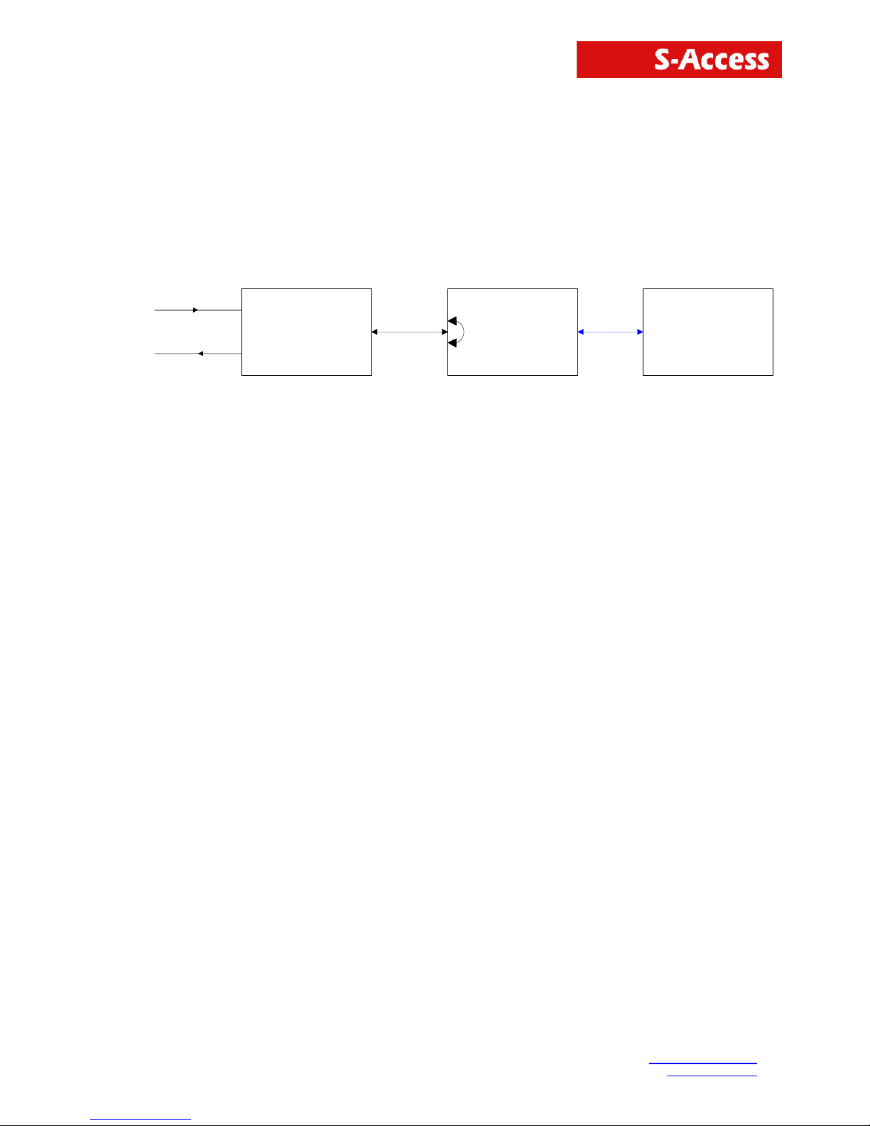
The test loop can be activated via the EOC service Channel interface.
Loop2
Repeater
SlaveMaster
TX
RX
C-Side channelN-Side channel
On the 4 wire repeater its only possible to activate the LOOP2 from the master over the EOC
channel. You will find the LOOP2 command in the maintenance menu of the LTU.
6 PERFORMANCE MONITORING
The monitoring of the xDSL signal is typically used during the installation and maintenance. Its
possible to monitor the xDSL link in two different ways.
The G.826 error parameters are designed to observe xDSL links over longer time periods.
The NM is used to determine the residual S/N value before the DSL link becomes critical.
Please refer to the “NM” and “G826” monitor commands described in the “S-Access Monitor”
section.
7 POWER
7.1 Power inputs
The unit can be feeded over the following inputs:
• Molex connector
• DSL line (remotely feeded from the LTU)
7.2 Wetting current
The unit is able to handle the wetting current feature. Please use the jumper description table for
the desired settings.
Page 11

SA-4W-REPEATER User Manual
S-Access GmbH
Tel: +41 44 700 31 11
Oberhausenstrasse 47
Page 11 of 26
8 MONITOR
8.1 General
The module can be connected to a terminal or a PC (with terminal emulation) in order to monitor
relevant events and to display additional information such as the signal quality of the xDSL link or
the G.826 error performance parameters. In addition, full system configuration and fault
localization can be done over the monitor interface
The terminal for monitoring should be VT100 compatible and configured as follows:
• 9600 baud, asynchronous
• 8 bits, no parity, one stop bit
• no new line on carriage return (i.e. no line feed on carriage return)
• flow control none
8.2 Structure & Organization
The structure and organization of the S-Access monitor is adapted to ITU-T Recommendation
M.3400 for TMNs with its five sub-sets.
Sub-set Short-form
Performance management PM
Fault and maintenance management FMM
Configuration management CM
Accounting management AM
Security management SM
A S-Access does neither support Accounting management nor Security management. AM and SM
are not in the monitor's main menu.
At any time, the <H> (“Help”) command shows and explains the available commands and their
parameters.
For details or a more precise explanation of a command type: H ´command´
The prompt on the screen consists of:
• a repeater indication (RR_)
• the repeater address indication
• the short form of the specified sub-set menu.
“RR_04_FMM>”.
Note:
Repeater address is calculated as repeater position (starting from CO side) in the xDSL
chain plus 2. Thus the repeater nearest to CO side has address 03, second one – 04, etc.
Page 12
SA-4W-REPEATER User Manual
S-Access GmbH
Tel: +41 44 700 31 11
Oberhausenstrasse 47
Page 12 of 26
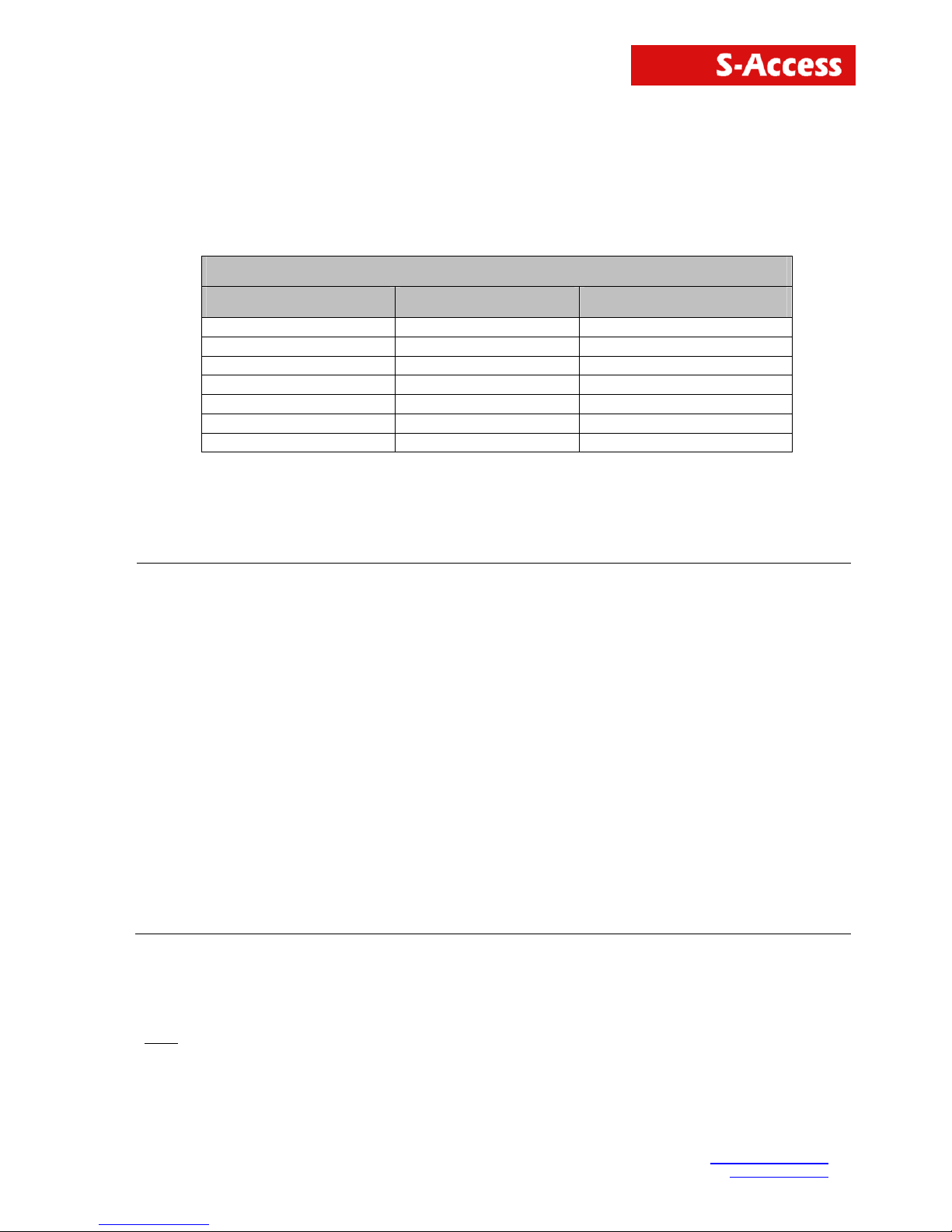
8.3 Repeater command tree
The repeater command set tree is shown below:
Main Menu
Performance Fault and Maintenance Configuration
G826 NM CONFIG
G826 C STATUS MODE
RESETG826 ALARM ANNEX
ALARM T BASERATE
RESET ADAPTIVE
DEFAULT
ID
Figure 8-1: Repeater Monitor Command Set Tree
8.3.1 Main Menu
SDSL Dual Pair Repeater
HW Rev. D1
SW Rev. 1.0.0.0
FW Rev. 1.10.3
Copyright (C) 2004 by S-Access GmbH
------------- Main Menu -----------------
1. Performance management (PM)
2. Fault and maintenance management (FMM)
3. Configuration management (CM)
5. Exit
-----------------------------------------
RR_00_MM>Select [1..5]:
To select the sub-menus type 1 to 5.
Note
: Each command must be terminated by a carriage return.
Page 13

SA-4W-REPEATER User Manual
S-Access GmbH
Tel: +41 44 700 31 11
Oberhausenstrasse 47
Page 13 of 26
8.3.2 Common Commands
Common commands are available in every sub menu.
8.3.2.1 HELP Command
By typing the letter "H" followed by [ENTER], all available commands of the actual sub menu are
displayed.
8.3.2.2 MAIN Command
By typing the letter "M" followed by [ENTER], you return to the Main Menu Screen.
8.3.2.3 DISCONNECT Command
This command will be only displayed if the unit is accessed from the LTU with the remote terminal
functionality.
With the disconnect command you will leave the remote terminal mode and return to the LTU
terminal mode.
8.3.3 Performance management PM
Performance management activated
Enter <M> to return to MAIN, or <H> for HELP information
Type <H> and the monitor lists all available commands in the performance sub-menu.
Page 14

SA-4W-REPEATER User Manual
S-Access GmbH
Tel: +41 44 700 31 11
Oberhausenstrasse 47
Page 14 of 26
8.3.3.1 G826 Command
The G826 command displays the ITU-T G.826 error performance on xDSL line side:
---------------------------------------------------------------------Master Side
G.826 Error Performance : CRC6-A FEBE-A CRC6-B FEBE-B
---------------------------------------------------------------------Errored blocks : 00000000 00000000 00000000 00000000
Errored seconds : 00000000 00000000 00000000 00000000
Severely errored seconds : 00000000 00000000 00000000 00000000
Background block errors : 00000000 00000000 00000000 00000000
Available time : 00000000 00000000 00000000 00000000
Unavailable time : 00000382 00000382 00000382 00000382
---------------------------------------------------------------------Slave Side
G.826 Error Performance : CRC6-A FEBE-A CRC6-B FEBE-B
---------------------------------------------------------------------Errored blocks : 00000000 00000000 00000000 00000000
Errored seconds : 00000000 00000000 00000000 00000000
Severely errored seconds : 00000000 00000000 00000000 00000000
Background block errors : 00000000 00000000 00000000 00000000
Available time : 00000000 00000000 00000000 00000000
Unavailable time : 00058651 00058651 00058651 00058651
---------------------------------------------------------------------RR_00_PM>
Option:
C Updates the G.826 parameters continuously
Definitions:
1. CRC6_x: Cyclic redundancy check indicating errored blocks received
on the local xDSL side.
2. FEBE_x: Far end block error indicating errored blocks received on the
remote xDSL side.
3. Errored blocks (EB): A block in witch one or more bits are in error.
4. Errored seconds (ES): A one second period with one or more errored blocks. SES
defined below is a subset of ES.
5. Severely errored second (SES): A one second period which contains >=30% errored blocks.
6. Background block error (BBE): An errored block not occurring as part of an SES.
Page 15

SA-4W-REPEATER User Manual
S-Access GmbH
Tel: +41 44 700 31 11
Oberhausenstrasse 47
Page 15 of 26
8.3.3.2 RESETG826 Command
The RESETG826 command sets the G.826 error performance parameters back to zero.
RR_00_PM>RESETG826
G.826 error performance parameter reset
RR_00_PM>
8.3.4 Fault and maintenance management FMM
Fault and maintenance management activated
Enter <M> to return to MAIN, or <H> for HELP information
Type <H>and the monitor lists all available commands in the fault and maintenance sub-menu.
8.3.4.1 NM Command
The NM command allows the user to switch on/off the signal quality of the DSL lines:
RR_00_FMM>NM
Noise margin trace on
xDSL NM: Mst-Side ChA: 10.9dB, ChB: 11.2dB Slv-Side ChA: 15.8dB, ChB: 15.4dB
Noise margin trace off
RR_00_FMM>
Page 16

SA-4W-REPEATER User Manual
S-Access GmbH
Tel: +41 44 700 31 11
Oberhausenstrasse 47
Page 16 of 26
8.3.4.2 STATUS Command
The STATUS command displays the actual system status:
---------------------------------------------------------------------Local System Status: N-Side CH A CH B C-Side CH A CH B
---------------------------------------------------------------------LOSD : 1 1 1 1
SEGA : 1 1 1 1
PS : 1 1 1 1
SEGD : 1 1 1 1
Tx power : 07.5 07.5 dBm 07.5 07.5 dBm
Rx gain : 13.4 13.7 dB 14.0 13.4 dB
Loop attn.: 00.0 00.0 dB 00.0 00.0 dB
NM : 26.2 27.0 dB 25.8 26.2 dB
Bitrate : 1024 1024 kBit/s 1024 1024 kBit/s
---------------------------------------------------------------------RR_03_FMM>
Definitions:
LOSD: (Loss of Signal) Indicates the loss of signal from the application
interface. Loss of Signal = 0, Normal = 1.
SEGA: (Segment Anomaly) Indicates a CRC error on the incoming xDSL
frame. A segment anomaly indicates that a regenerator operating
on a segment has received corrupted data and therefore the
regenerated data is unreliable. CRC Error =0, Normal = 1.
PS: (Power Status)
SEGD: (Segment Defect)
Tx power: Local transmit power in dBm
Rx gain: Local receiver gain in dB
Loop attn.: Estimate of the loop attenuation in dB of the actual connection
NM: Noise margin
Bitrate: Bitrate of the actual connection
8.3.4.3 ALARM Command
The ALARM command displays the actual alarm status:
CO_01_FMM> ALARM
RR_03_FMM>
---------------------------------------------------------------------Local Alarm Status: Mst-Side CH A CH B Slv-Side CH A CH B
---------------------------------------------------------------------LOS/LFA-H: off off off off
SEGD : off off off off
BER-H : off off off off
LOOP2 : off
---------------------------------------------------------------------RR_03_FMM>CO_01_FMM>
Options:
T Turns alarm trace on / off
Page 17

SA-4W-REPEATER User Manual
S-Access GmbH
Tel: +41 44 700 31 11
Oberhausenstrasse 47
Page 17 of 26
Definitions:
LOS/LFA-H: Loss of signal or frame alignment at xDSL loop
SEGD: Segment Defect indication
BER-H:
xDSL block-error-rate according G.826 ≥ 30%
LOOP2: xDSL test loop 2 active
8.3.4.4 RESET Command
By typing RESET, the system unit will be restarted.
CO_01_FMM> RESET
system reset
8.3.5 Configuration management CM
Configuration management activated
Enter <M> to return to MAIN, or <H> for HELP information
Type <H> and the monitor lists all available commands in the configuration sub-menu.
8.3.5.1 General note
If the repeater works in 4 wire mode the commands ANNEX, BASERATE, RATEADAPTION
in some modes the user has to enter 2 parameters.
Example: Annex A,B
8.3.5.2 CONFIG Command
The CONFIG command displays the configuration of the unit.
8.3.5.3 MODE Command
This command sets the operation mode.
Parameters: S → Normal mode
D → Dual pair mode
8.3.5.4 ANNEX Command
This command sets the Annex to the desired mode.
Parameters: A → Annex A
B → Annex B
AUTO → Auto selection
8.3.5.5 ID Command
This command sets a unique identification string printed on the main screen.
Page 18

SA-4W-REPEATER User Manual
S-Access GmbH
Tel: +41 44 700 31 11
Oberhausenstrasse 47
Page 18 of 26
8.3.5.6 BASERATE Command
This command sets the base rate for xDSL interface. This value must be between 3 and 32 and
defines the available 64 kbit/s channels. To optimize the bandwidth of your connection, you have to
set the base rate value to the maximum where you get a stable connection.
Parameters: 3 → 32
8.3.5.7 ADAPTIVE Command
Set rate adaption on / off.
Parameters: on
off
8.3.5.8 DEFAULT Command
The DEFAULT command sets a default configuration. Six default settings are available (three for
master, three for slave) in each of following modes: E1 only Normal or Dual Pair mode; Nx64 only
Normal or Dual Pair mode; fE1 &Nx64 Normal or Dual Pair mode and Multipoint Mode.
Page 19
SA-4W-REPEATER User Manual
9 SOFTWARE UPDATE
9.1 General
The software of the S-Access boards has the possibility for field updates. To do a field update, you
need only a Windows 95/98/NT computer, the Flash Loader program installed, a connection
between the Windows computer and the repeater Monitor connector and the newest release of the
S-Access software.
Note: The software has to be downloaded to the Main- and Upper board.
9.2 Software download
To update the software on your repeater you have to run through the following steps:
1. Switch off the power of your repeater.
2. Connect the repeater monitor connector with your Windows computer’s RS232 interface.
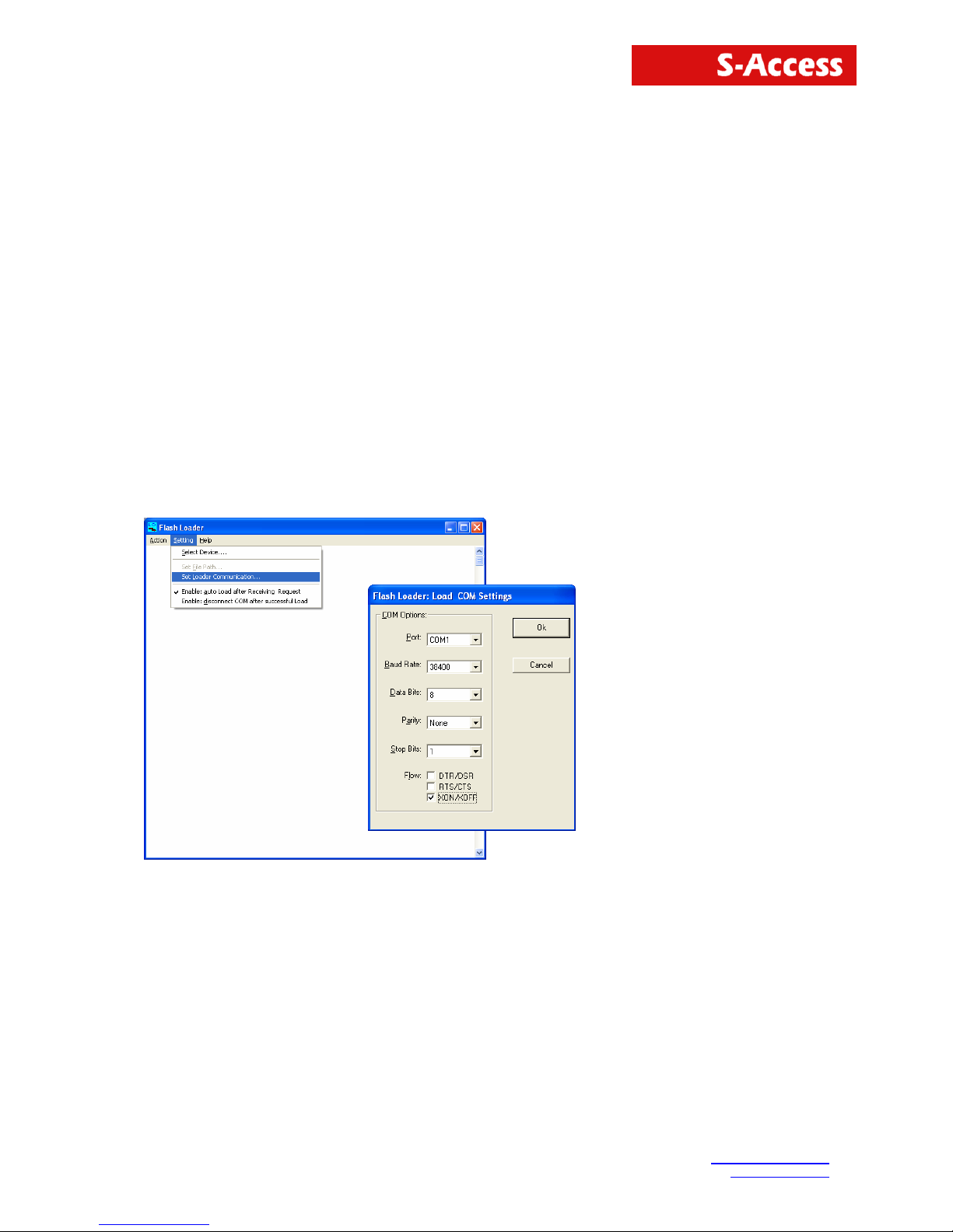
3. Start the Flash Loader software on your Windows computer
4. Choose Set Loader Communication in the menu Setting. Select the right communication port,
the communication information and press Ok.
S-Access GmbH
Tel: +41 44 700 31 11
Oberhausenstrasse 47
Page 19 of 26
Page 20
SA-4W-REPEATER User Manual
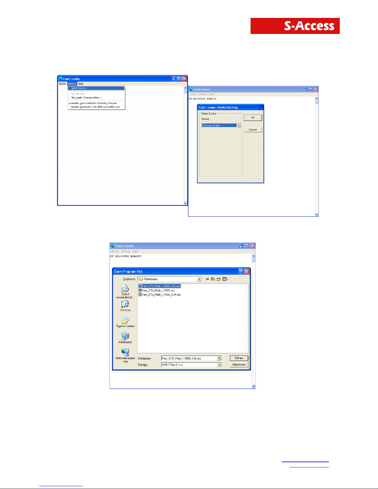
5. Choose Select Device in the Setting menu, select the device S-Access and press Ok.
6. Choose the newest software version and press Öffnen.
S-Access GmbH
Tel: +41 44 700 31 11
Oberhausenstrasse 47
Page 20 of 26
Page 21
SA-4W-REPEATER User Manual
S-Access GmbH
Tel: +41 44 700 31 11
Oberhausenstrasse 47
Page 21 of 26
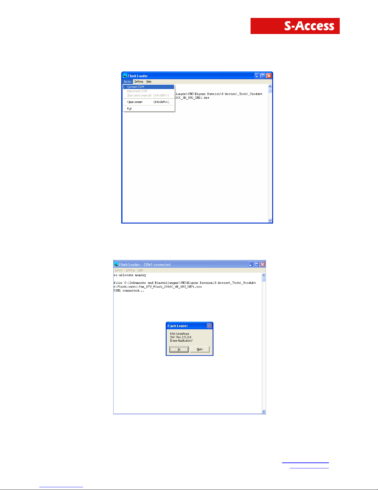
7. Execute the command Connect COM in the menu Action.
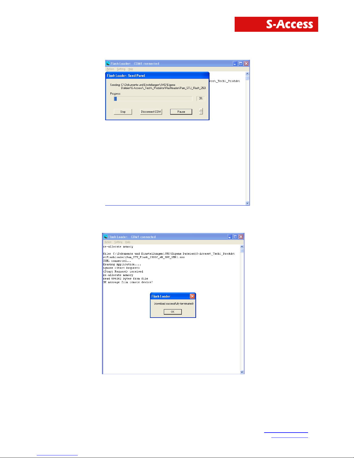
8. Switch on the power of your repeater.
9. The following message appears on the screen, then press Ja.
Page 22
SA-4W-REPEATER User Manual
S-Access GmbH
Tel: +41 44 700 31 11
Oberhausenstrasse 47
Page 22 of 26
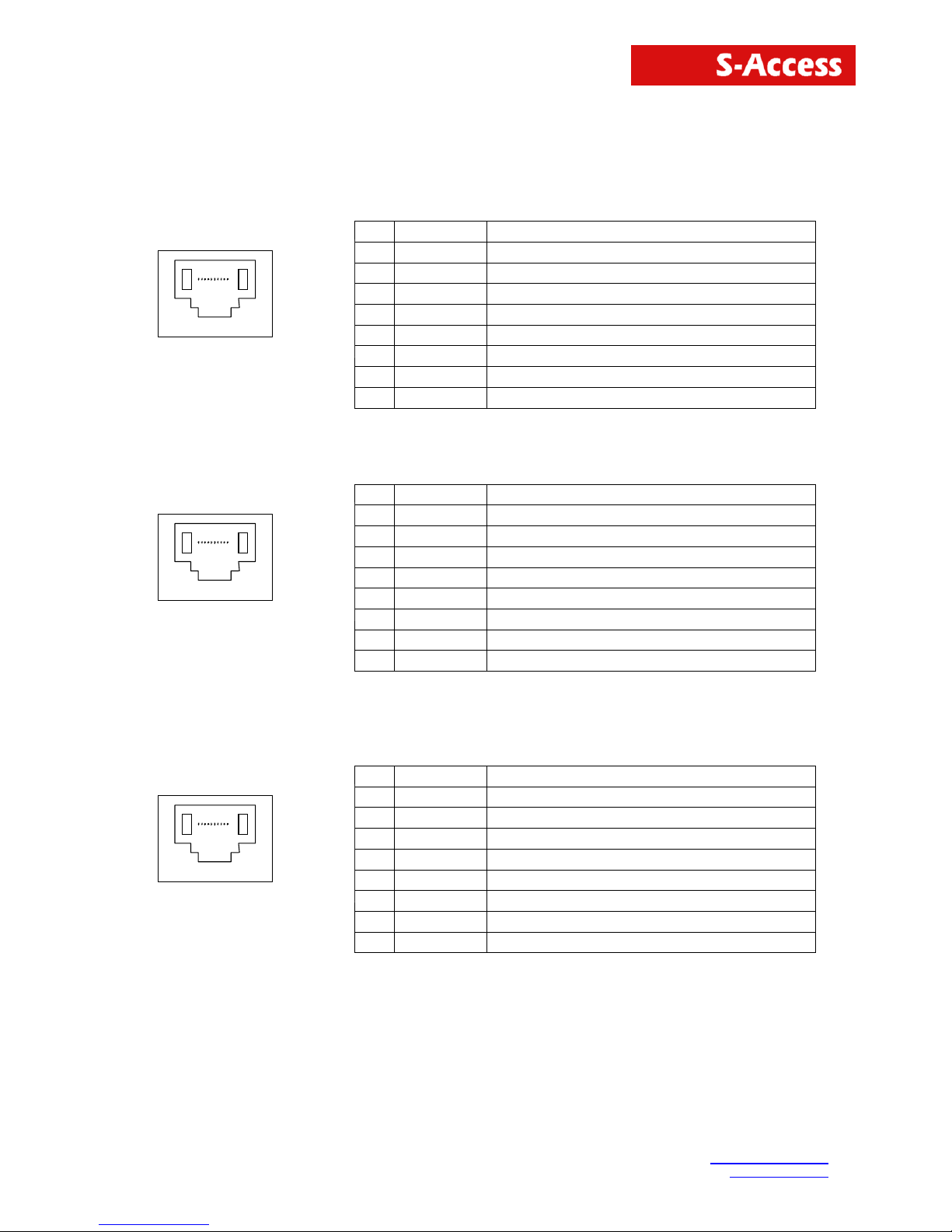
10. On the Windows screen you see the ongoing download.
11. If the download is successfully finished the Flash Loader program sends the following
message:
Page 23
SA-4W-REPEATER User Manual
S-Access GmbH
Tel: +41 44 700 31 11
Oberhausenstrasse 47
Page 23 of 26
10 CONNECTOR DESCRIPTION
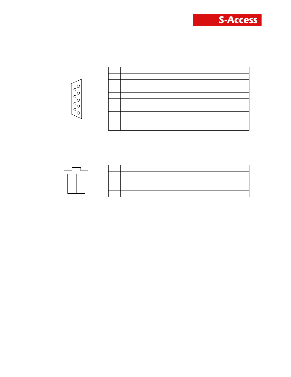
10.1 4 wire xDSL Connector Mainboard (Slave/CPE)
Pin Signal Description
1 NC Not used
2 NC Not used
3 RXB.a Loop B, Tip (Slave-N-side)
4 RXA.a Loop A, Tip (Slave-N-side)
5 RXA.b Loop A, Ring (Slave-N-side)
6 RXB.b Loop B, Ring (Slave-N-side)
7 NC Not used
Fro nt View
RJ45-8
1
8
8 NC Not used
10.2 4 wire xDSL Connector Upperboard (Master/COE)
Pin Signal Description
1 NC Not used
2 NC Not used
3 TXB.a Loop B, Tip (Master-C-side)
4 TXA.a Loop A, Tip (Master-C-side)
5 TXA.b Loop A, Ring (Master-C-side)
6 TXB.b Loop B, Ring (Master-C-side)
7 NC Not used
Fro nt View
RJ45-8
1
8
8 NC Not used
10.3 2 wire xDSL Connector only Mainboard is required
Pin Signal Description
1 NC Not used
2 NC Not used
3 TXB.a Loop B, Tip (Master-C-side)
4 RXA.a Loop A, Tip (Slave-N-side)
5 RXA.b Loop A, Ring (Slave-N-side)
6 TXB.b Loop B, Ring (Master-C-side)
7 NC Not used
Fro nt View
RJ45-8
1
8
8 NC Not used
Page 24
SA-4W-REPEATER User Manual
S-Access GmbH
Tel: +41 44 700 31 11
Oberhausenstrasse 47
Page 24 of 26
10.4 Monitor Interface
Pin Signal Description
1 FPE Functional Protective Earth
2 TXD EIA-232 Transmit Data
3 RXD EIA-232 Receive Data
4 NC Not used
5 SGND EIA-232 Signal Ground
6 NC Not used
7 NC Not used
8 NC Not used
5
1
9
6
9 NC Not used
* on NTU only
10.5 Power Interface
Pin Signal Description
1 -MainsPWR -48/60Vdc
2 FPE Functional Protective Earth
3 NC -
43
21
4 +PWR Positive power supply terminal (0V)
Molex Mini-Fit, 4-pin
Page 25

SA-4W-REPEATER User Manual
S-Access GmbH
Tel: +41 44 700 31 11
Oberhausenstrasse 47
Page 25 of 26
11 TECHNICAL SPECIFICATION
11.1 Interfaces
11.1.1 xDSL Line Interface
Specification ITU-T G.SHDSL, Rec G.991.2
Option 4-wire Interface (separate Tx and Rx Pairs)
Line Code TC-PAM
Impedance 135
Transmit Power
13.5 dBm @ 135 Ω
Number of Pairs 1 or 2 (option: 2 or 4)
Bit Rate 192 to 2064 kbps
Connector Type RJ-45, 8 pin
Overvoltage Protection ITU-T Rec. K.20/K.21
Specification ITU-T G.SHDSL, Rec G.991.2
Wetting Current 2-4 mA @ 60 V
11.1.2 Monitor Interface
Specification EIA-232 / V.28
Data Rate 9600 baud, asynchronous
Protocol 8 bit, no parity, 1 stop bit no linefeed with carriage return
XON/XOFF enabled
Signal Level V.28 on DB9 female connector
Connector Type DB9 female connector
11.2 Power Supply
Specification ETSI ETS 300 132-2
Plug-in 2 x 40V/60V
DC
over backpanel (redundant)
Tabletop 1 x 48Vdc (36-72V
DC)
over Molex type safety approved
connector or
38..200Vdc over xDSL
11.3 Environmental
11.3.1 Climatic Conditions
Storage: ETS 300 019-1-1 Class 1.2
(-25°C … +55°C)
Transportation: ETS 300 019-1-2 Class 2.3
(-40°C … +70°C)
Operation: ETS 300 019-1-3 Class 3.2
(-5°C … +45°C)
11.3.2 Safety / EMC
According to EN60950 / EN55022, Class B
11.4 Physical Dimensions and Weight
IP: Dimensions: 300(W)x166(D)x65(H) mm
Weight: 2.5 kg
Page 26

SA-4W-REPEATER User Manual
S-Access GmbH
Tel: +41 44 700 31 11
Oberhausenstrasse 47
Page 26 of 26
12 APPENDICES
12.1 Standards
ETSI ETR 152, “Transmission and Multiplexing (TM); High Bit Rate Digital Subscriber Line (xDSL)
Transmission System on Metallic Local Lines; xDSL Core Specification and Applications for 2048
kbit/s Based Access Digital Sections”
ITU-T G.821, “Error Performance of an International Digital Connection Forming Part of an
Integrated Services Digital Network”
ITU-T G.826, “Error Performance Parameters and Objectives for International, Constant Bit Rate
Digital Paths at or above the Primary Rate”
ITU-T G.823, “The Control of Jitter and Wander within Digital Networks Which Are Based on the
2048 kbit/s Hierarchy”
ITU-T G.703, “Physical/Electrical Characteristics of Hierarchical Digital Interfaces”
ITU-T G.704, “Synchronous Frame Structures Used at Primary and Secondary Hierarchical Levels”
ITU-T M.3400, “TMN Management Functions”
ITU-T K.20, “Resistibility of Telecommunication Switching Equipment to Over voltages and
Overcurrents”
ITU-T K.21, “Resistibility of Subscribers’ Terminals to Over voltages and Over currents”
EN 60950, “Safety of Information Technology Equipment Including Electrical Business Equipment”
EN 55022, “Grenzwerte und Messverfahren für Funkstörungen von informationstech-nischen
Einrichtungen”
ETS 300 019, “Equipment Engineering; Environmental Conditions and Environmental Tests for
Telecommunications Equipment”
 Loading...