

Page 1

www.servicemanualall.com
Buy, Download, Print...
Sabre Lawn Tractor
38–Inch and 46–Inch (96 cm and 117 cm)
Models: 1338 Gear
1538 Gear
1538 Hydro
15538 Gear
15538 Hydro
1546 Gear
1638 Hydro
1646 Gear
1646 Hydro
Technical Manual
www.servicemanualall.com
John Deere Consumer Products Group
TM–GX10131 (Mar–97)
LITHO IN U.S.A. (New)
Page 2

This technical manual is written for an experienced
technician and contains sections that are specifically for
this product. It is a part of a total product support
program.
The manual is organized so that all the information on a
particular system is kept together. The order of grouping
is as follows:
INTRODUCTION
Safety
Specifications and
Information
• Table of Contents
• Specifications
• Component Location
• System Schematic
• Theory of Operation
• Troubleshooting Chart
• Diagnostics
• Tests & Adjustments
• Repair
Note: Depending on the particular section or system
being covered, not all of the above groups may be
used.
Each section will be identified with a symbol rather than a
number. The groups and pages within a section will be
consecutively numbered.
We appreciate your input on this manual. If you find any
errors, or want to comment on the layout of the manual,
please mail your comments back to us.
Engine
Electrical
Gear Power Train
Hydrostatic Power Train
All information, illustrations and
specifications in this manual are based on
the latest information available at the time of
publication. The right is reserved to make
changes at any time without notice.
©
COPYRIGHT
Deere & Co.
John Deere Worldwide Lawn and
Grounds Care Division
Power Products Group
P.O. Box 7047
Charlotte, NC 28241
All rights reserved
3/5/97 1 - 1
www.servicemanualall.com
1997
Steering
Attachments
Miscellaneous
Service Information Bulletins
M
S
Page 3

SAFETY
HANDLE FLUIDS SAFELY-AVOID
FIRES
• BE PREPARED FOR EMERGENCIES
HANDLE CHEMICAL PRODUCTS
SAFELY
TS1133
Direct exposure to hazardous chemicals can cause
serious injury. Potentially hazardous chemicals used
include such items as lubricants, coolants, paints, and
adhesives.
A Material Safety Data Sheet (MSDS) provides specific
details on chemical products: physical and health
hazards, safety procedures, and emergency response
techniques. Check the MSDS before you start any job
using a hazardous chemical. That way you will know
exactly what the risks are and how to do the job safely.
Then follow procedures and recommended equipment.
When you work around fuel, do not smoke or work near
heaters or other fire hazards.
Store flammable fluids away from fire hazards. Do not
incinerate or puncture pressurized containers.
Make sure machine is clean of trash, grease, and
debris.
Do not store oily rags; they can ignite and burn
spontaneously.
Be prepared if a fire starts.
Keep a first aid kit and fire extinguisher handy.
Keep emergency numbers for doctors, ambulance
service, hospital, and fire department near your
telephone.
• DISPOSE OF WASTE PROPERLY
Improperly disposing of waste can threaten the
environment and ecology. Potentially harmful waste
includes oil, fuel, coolant, brake fluid, filters, and
batteries. Use leakproof containers when draining
fluids. Do not use food or beverage containers that
may mislead someone into drinking from them. Do not
pour waste onto the ground, down a drain, or into any
water source. Inquire on the proper way to recycle or
dispose of waste from your local environmental or
recycling center.
1 - 2
www.servicemanualall.com
3/5/97
Page 4

SAFETY
USE CARE IN HANDLING AND
SERVICING BATTERIES
• PREVENT BATTERY EXPLOSIONS
• Keep sparks, lighted matches, and open flame
away from the top of battery. Battery gas can
explode.
• Never check battery charge by placing a metal
object across the posts. Use a volt-meter or
hydrometer.
• Do not charge a frozen battery; it may explode.
Warm battery to 16°C (60°F).
• PREVENT ACID BURNS
• Sulfuric acid in battery electrolyte is poisonous. It is
strong enough to burn skin, eat holes in clothing,
and cause blindness if splashed into eyes.
• Avoid acid burns by:
1. Wearing eye protection and rubber gloves.
2. Avoiding breathing fumes from electrolyte.
3. Avoiding tipping battery.
4. Use proper jump start procedure.
USE SAFE SERVICE PROCEDURES
• WEAR PROTECTIVE CLOTHING
Wear close fitting clothing and safety equipment
appropriate to the job.
Prolonged exposure to loud noise can cause
impairment or loss of hearing. Wear a suitable hearing
protective device such as earmuffs or earplugs to
protect against objectionable or uncomfortable loud
noises.
Operating equipment safely requires the full attention
of the operator. Do not wear radio or music
headphones while operating machine.
• SERVICE MACHINES SAFELY
Tie long hair behind your head. Do not wear a necktie,
scarf, loose clothing, or necklace when you work near
machine tools or moving parts. If these items were to
get caught, severe injury could result.
Remove rings and other jewelry to prevent electrical
shorts and entanglement in moving parts.
• If you spill acid on yourself:
1. Flush your skin with water.
2. Apply baking soda to help neutralize the acid.
3. Flush your eyes with water for 10–15 minutes.
4. Get medical attention immediately.
• If acid is swallowed:
1. Drink large amounts of water or milk.
2. Then drink milk of magnesia, beaten eggs, or
vegetable oil.
3. Get medical attention immediately.
3/5/97 1 - 3
www.servicemanualall.com
• USE PROPER TOOLS
Use tools appropriate to the work. Makeshift tools and
procedures can create safety hazards. Use power tools
only to loosen threaded parts and fasteners. For
loosening and tightening hardware, use the correct
size tools. DO NOT use U.S. measurement tools on
metric fasteners. Avoid bodily injury caused by slipping
wrenches. Use only service parts meeting John Deere
specifications.
Page 5

SAFETY
• PARK MACHINE SAFELY
1. Depress brake pedal fully.
2. Move park lever into lock position.
3. Check that shift lever has returned to neutral.
4. Make sure blade drive lever is pulled back fully.
5. Move throttle lever to SLOW IDLE position and
allow engine to idle for approximately 30 seconds
before turning key switch to OFF position. Remove
the ignition key to prevent accidental starting.
• Before working on the machine:
1. Lower all equipment to the ground.
2. Stop the engine and remove the key.
3. Disconnect the battery ground strap.
4. Hang a “DO NOT OPERATE” tag in operator
station.
• WORK IN CLEAN AREA
• Before starting a job
1. Clean work area and machine:
2. Have all the necessary tools to do your job
3. Have the right parts on hand.
4. Read all instructions thoroughly; do not attempt
shortcuts.
• ILLUMINATE WORK AREA SAFELY
Illuminate your work area adequately but safely. Use a
portable safety light for working inside or under the
machine. Make sure the bulb is enclosed by a wire
cage. The hot filament of an accidentally broken bulb
can ignite spilled fuel or oil.
• WORK IN VENTILATED AREA
• SUPPORT MACHINE PROPERLY AND USE
PROPER LIFTING EQUIPMENT
TS229
If you must work on a lifted machine or attachment,
securely support the machine or attachment with jack
stands rated to support the lifted load.
Do not support the machine on cinder blocks, hollow
tiles, or props that may crumble under continuous load.
Do not work under a machine that is supported solely
by a jack. Follow recommended procedures in this
manual.
Lifting heavy components incorrectly can cause severe
personal injury or machine damage. Follow
recommended procedure for removal and installation
of components in the manual.
Engine exhaust fumes can cause sickness or death. If
it is necessary to run an engine in an enclosed area,
remove the exhaust fumes from the area with an
exhaust pipe extension.
If you do not have an exhaust pipe extension, open the
doors and get outside air into the area.
WARNING: California Proposition 65 Warning
Diesel engine exhaust and some of its constituents are
known to the State of California to cause cancer, birth
defects, and other reproductive harm.
Gasoline engine exhaust from this product contains
chemicals known to the State Of California to cause
cancer, birth defects, or other reproductive harm.
• REMOVE PAINT BEFORE WELDING OR HEATING
Avoid potentially toxic fumes and dust. Hazardous
fumes can be generated when paint is heated by
welding, soldering, or using a torch. Do all work outside
or in a well ventilated area. Dispose of paint and
solvent properly. Remove paint before welding or
heating: If you sand or grind paint, avoid breathing the
dust. Wear an approved respirator. If you use solvent
or paint stripper, remove stripper with soap and water
before welding. Remove solvent or paint stripper
containers and other flammable material from area.
Allow fumes to disperse at least 15 minutes before
welding or heating.
1 - 4
www.servicemanualall.com
3/5/97
Page 6

SAFETY
• AVOID HARMFUL ASBESTOS DUST
Avoid breathing dust that may be generated when
handling components containing asbestos fibers.
Inhaled asbestos fibers may cause lung cancer.
Components in products that may contain asbestos
fibers are brake pads and some gaskets. The asbestos
used in these components is usually found in a resin or
sealed in some way. Normal handling is not hazardous
as long as airborne dust containing asbestos is not
generated.
Avoid creating dust. Never use compressed air for
cleaning. Avoid brushing or grinding material
containing asbestos. When servicing, wear an
approved respirator. A special vacuum cleaner is
recommended to clean asbestos. If not available, apply
a mist of oil or water on the material containing
asbestos. Keep bystanders away from the area.
• SERVICE TIRES SAFELY
REPLACE DECALS
Replace missing or damaged Decals. See the machine
operator's manual for correct safety sign placement.
LIVE WITH SAFETY
Explosive separation of a tire and rim parts can cause
serious injury or death.
Do not attempt to mount a tire unless you have the
proper equipment and experience to perform the job.
Always maintain the correct tire pressure. Do not inflate
the tires above the recommended pressure. Never
weld or heat a wheel and tire assembly. The heat can
cause an increase in air pressure resulting in a tire
explosion. Welding can structurally weaken or deform
the wheel.
When inflating tires, use a clip-on chuck and extension
hose long enough to allow you to stand to one side and
NOT in front of or over the tire assembly. Use a safety
cage if available.
• Check wheels for low pressure, cuts, bubbles,
damaged rims or missing retaining hardware.
Before returning machine to customer, make sure
machine is functioning properly, especially the safety
systems. Install all guards and shields.
3/5/97 1 - 5
www.servicemanualall.com
Page 7

SAFETY
1 - 6
www.servicemanualall.com
3/5/97
Page 8

SPECIFICATIONS & INFORMATION CONTENTS
CONTENTS
Page
SPECIFICATIONS & INFORMATION
SPECIFICATIONS . . . . . . . . . . . . . . . . . . . . . . . . . . . . . . . . . . . . . . . . . . . 2
UNIFIED INCH TORQUE VALUES . . . . . . . . . . . . . . . . . . . . . . . . . . . . . . 6
METRIC TORQUE VALUES . . . . . . . . . . . . . . . . . . . . . . . . . . . . . . . . . . . 7
GASOLINE SPECIFICATIONS . . . . . . . . . . . . . . . . . . . . . . . . . . . . . . . . . 8
GASOLINE STORAGE . . . . . . . . . . . . . . . . . . . . . . . . . . . . . . . . . . . . . . . . . . . . . . . . 8
LUBRICANT SPECIFICATIONS . . . . . . . . . . . . . . . . . . . . . . . . . . . . . . . . 8
ENGINE OIL . . . . . . . . . . . . . . . . . . . . . . . . . . . . . . . . . . . . . . . . . . . . . . . . . . . . . . . . 8
GREASE . . . . . . . . . . . . . . . . . . . . . . . . . . . . . . . . . . . . . . . . . . . . . . . . . . . . . . . . . . . 9
ALTERNATIVE LUBRICANTS . . . . . . . . . . . . . . . . . . . . . . . . . . . . . . . . . . . . . . . . . . . 9
SYNTHETIC LUBRICANTS. . . . . . . . . . . . . . . . . . . . . . . . . . . . . . . . . . . . . . . . . . . . . 9
OIL FILTERS . . . . . . . . . . . . . . . . . . . . . . . . . . . . . . . . . . . . . . . . . . . . . . . . . . . . . . . . 9
LUBRICANT STORAGE . . . . . . . . . . . . . . . . . . . . . . . . . . . . . . . . . . . . . . . . . . . . . . . 9
SERIAL NUMBER LOCATIONS . . . . . . . . . . . . . . . . . . . . . . . . . . . . . . . 10
TRACTOR IDENTIFICATION NUMBER . . . . . . . . . . . . . . . . . . . . . . . . . . . . . . . . . . 10
ENGINE SERIAL NUMBER. . . . . . . . . . . . . . . . . . . . . . . . . . . . . . . . . . . . . . . . . . . . 10
GEAR TRANSAXLE SERIAL NUMBER . . . . . . . . . . . . . . . . . . . . . . . . . . . . . . . . . . 10
HYDROSTATIC TRANSMISSION SERIAL NUMBER — K55. . . . . . . . . . . . . . . . . . 10
HYDROSTATIC TRANSMISSION SERIAL NUMBER — K51. . . . . . . . . . . . . . . . . . 10
3/5/97 2 - 1
www.servicemanualall.com
Page 9

SPECIFICATIONS SPECIFICATIONS & INFORMATION
SPECIFICATIONS
Engine:
Make . . . . . . . . . . . . . . . . . . . . . . . . . . . . . . . . . . . . . . . . . . . . . . . . . Briggs and Stratton
Style . . . . . . . . . . . . . . . . . . . . . . . . . . . . . . . . . . . . . . . . . . . . . . . . . . . . . . Vertical Shaft
Models:
13 Horsepower . . . . . . . . . . . . . . . . . . . . . . . . . . . . . . . . . . . . . . . . . . . . . . . . 28M707
15 Horsepower . . . . . . . . . . . . . . . . . . . . . . . . . . . . . . . . . . . . . . . . . . . . . . . . 28N700
16 Horsepower (Cast Iron Sleeve) . . . . . . . . . . . . . . . . . . . . . . . . . . . . . . . . . 28Q777
Type . . . . . . . . . . . . . . . . . . . . . . . . . . . . Gasoline, Air Cooled, Single Cylinder, 4-Cycle
Crankcase Oil Capacity. . . . . . . . . . . . . . . . . . . . . . . . . . . . . . . . . . . . . . . . . . . . . 3 Pints
Oil: Warm Climate (Above 40°F) . . . . . . . . . . . . . . . . . . . . . . . .SE, SF, SG, SAE 30W
Cold Climate (Below 40°F). . . . . . . . . . . . . . . . . . . . . . . .SE, SF, SG, SAE 10W30
Electrical:
®
Ignition System . . . . . . . . . . . . . . . . . . . . . . . . . . . . . . . . . Magnetron
Magneto Air Gap . . . . . . . . . . . . . . . . . . . . . . . . . . . . . 0.25 -0.35 mm (0.010 - 0.014 in.)
Charging System. . . . . . . . . . . . . . . . . . . . . . . . . . . . . . . . . . . . . . . Dual Circuit (AC/DC)
Charging Capacity. . . . . . . . . . . . . . . . 2-4 amps, 14 volts DC@3600 rpm (Unregulated)
Spark Plugs
13 Hp. . . . . . . . . . . . . . . . . . . . . . . . . . . . . . . . . . . . . . . . TY6129 (Champion RJ-19 LM)
15 & 16 Hp . . . . . . . . . . . . . . . . . . . . . . . . . . . . . . . . . . M78543 (Champion RC-12 YC)
Spark Plug Air Gap . . . . . . . . . . . . . . . . . . . . . . . . . . . . . . . . . . . . . . 0.76 mm (0.030 in.)
Battery Type . . . . . . . . . . . . . . . . . . . . . . . . . . . . . . . . . . . . . . . . . . . . . . .BCI Group, U1
Battery Cranking Amps . . . . . . . . . . . . . . . . . . . . . . . . . . . . . . .230 amps at 0° C (32° F)
Battery Cold Cranking Amps. . . . . . . . . . . . . . . . . . . . . . . . . . .190 amps at 0° C (32° F)
Battery Specific Gravity. . . . . . . . . . . . . . . . . . . . . . . . . . . . . . . . . . . Above 1.225 Points
Starter Type. . . . . . . . . . . . . . . . . . . . . . . . . . . . . . . . . . . . . . . . . . . . Bendix Inertia Drive
Fuel Shut-Off Solenoid (16 H.P. Only). . . . . Replaceable (Below Carburetor Float Bowl)
Headlight Bulbs . . . . . . . . . . . . . . . . . . . . . . . . . . . . . . . . . . . . . . . . . . Type 1156, 12 Volt
Magneto Ignition
Fuel/Air System:
Carburetor Make . . . . . . . . . . . . . . . . . . . . . . . . . . . . . . . . . . . . . . . . . . Briggs & Stratton
Carburetor Type . . . . . . . . . . . . . . . . . . . . . . . . . . . . . . . . . . . . . . . . . . . . . . . Side Draft
Throttle/Choke. . . . . . . . . . . . . . . . . . . . . . . . . . . . . . . . . . . . . . Unitized Control Linkage
Carburetor Fuel Shut-Off Solenoid ( Optional) . . . . . . . . . . . . . . . . . . . . . . . . . . .Electric
Fuel Delivery . . . . . . . . . . . . . . . . . . . . . . . . . . . . . . . . . . . . . . . . . . . . . . . . Gravity Flow
Fuel Filter . . . . . . . . . . . . . . . . . . . . . . . . . . . . . . . . . . . . . . . . . . Replaceable Inline type
Fuel Type . . . . . . . . . . . . . . . . . . . . . . . . . . . . . . . . . . . Unleaded (87 Octane Minimum)
Fuel Tank Capacity . . . . . . . . . . . . . . . . . . . . . . . . . . . . . . . . . . . . . . . . . 4.7 L (1.25 gal)
Air Filter. . . . . . . . . . . . . . . . . . . . . . . . . . . . . . . . Paper Element with Foam Pre-cleaner
Muffler Type. . . . . . . . . . . . . . . . . . . . . . . . . . . . . . . . . . . . . . . . . . . . . . . . . Anti-Backfire
2 - 2 3/5/97
www.servicemanualall.com
Page 10

SPECIFICATIONS & INFORMATION SPECIFICATIONS
Power Train—K55 Transmission:
Gear Transaxle—
Make . . . . . . . . . . . . . . . . . . . . . . . . . . . . . . . . . . . . . . . . . . . . . . . . . . . . . . . . . . Dana
Model. . . . . . . . . . . . . . . . . . . . . . . . . . . . . . . . . . .Spicer Heavy-Duty 4360 Transaxle
Type. . . . . . . . . . . . . . . . . . . . . . . . . . . . . . . . . . . . . . . . . . . . .Five-Speed/Linear Shift
Domestic Ground Speeds (at FAST idle—3350 rpm) and Gear Ratios:
1st Gear. . . . . . . . . . . . . . . . . . . . . . . . . . . . . . . . . . . . . 2.4 km/hr (1.5 mph)—61.67:1
2nd Gear . . . . . . . . . . . . . . . . . . . . . . . . . . . . . . . . . . . . 3.2 km/hr (2.0 mph)—46.67:1
3rd Gear . . . . . . . . . . . . . . . . . . . . . . . . . . . . . . . . . . . . 5.0 km/hr (3.1 mph)—30.00:1
4th Gear . . . . . . . . . . . . . . . . . . . . . . . . . . . . . . . . . . . . 6.4 km/hr (4.0 mph)—23.48:1
5th Gear . . . . . . . . . . . . . . . . . . . . . . . . . . . . . . . . . . . . 8.0 km/hr (5.0 mph)—18.46:1
Reverse . . . . . . . . . . . . . . . . . . . . . . . . . . . . . . . . . . . . . 3.7 km/hr (2.3 mph)—40.00:1
Brake Type . . . . . . . . . . . . . . . . . .Single, External Brake Disc With Dual Friction Pucks
Lubrication—Input Shaft Needle Bearings . . . . . . . . . . . . . . . . . . Multi-Purpose Grease
Lubrication—Transaxle . . . . . . . . . . . . . . . . . . . . . . . . . . . . . . . . . Multi-Purpose Grease
Capacity—Transaxle. . . . . . . . . . . . . . . . . . . . . . . . . . . . . . . . . . . . . .0.64 kg (1.406 lbs)
Hydro Transaxle—
Make . . . . . . . . . . . . . . . . . . . . . . . . . . . . . . . . . . . . . . . . . . . . . . . . . . . . . . . . Kanzaki
Model. . . . . . . . . . . . . . . . . . . . . . . . . . . . . . . . . . . . . . . . . . .Tuff Torq
®
K55 Transaxle
Type. . . . . . . . . . . . . . . . . . . . . . . . . . . . . . . . . . . . . . . . . . . . . . . . . . . . . . Hydrostatic
Ground Speeds (at FAST idle—3350 rpm):
Forward . . . . . . . . . . . . . . . . . . . . . . . . . . . . . . . . . . . . . 0—8.66 km/hr (0—5.38 mph)
Reverse . . . . . . . . . . . . . . . . . . . . . . . . . . . . . . . . . . . . . 0—4.24 km/hr (0—2.62 mph)
Brake Type . . . . . . . . . . . . . . . . . . . . . . Single, External Disc Brake With Friction Pucks
Lubrication. . . . . . . . . . . . . . . . . . . . . . . . . . . . . . . . . . . . . 10W30 Engine Oil, Class CD
Reservoir. . . . . . . . . . . . . . . . . . . . . . . . . . . . . . . . . . . . . . . . . . . . . . . . . . . . . . . Internal
Capacity . . . . . . . . . . . . . . . . . . . . . . . . . . . . . . . . . . . . . . . . . . . . . . . . . . . 1.6 L (3.4 pt)
Power Train—K51 Transmission:
Gear Transaxle—
Make . . . . . . . . . . . . . . . . . . . . . . . . . . . . . . . . . . . . . . . . . . . . . . . . . . . . . . . . . . Dana
Model. . . . . . . . . . . . . . . . . . . . . . . . . . . . . . . . . . . . . . . . . . . . . Spicer K51 Transaxle
Type. . . . . . . . . . . . . . . . . . . . . . . . . . . . . . . . . . . . . . . . . . . . .Five-Speed/Linear Shift
Domestic Ground Speeds (at FAST idle—2950 rpm) and Gear Ratios:
1st Gear. . . . . . . . . . . . . . . . . . . . . . . . . . . . . . . . . . . . . . . . . . . . . 2.4 km/hr (1.5 mph)
2nd Gear . . . . . . . . . . . . . . . . . . . . . . . . . . . . . . . . . . . . . . . . . . . .3.2 km/hr (2.0 mph)
3rd Gear . . . . . . . . . . . . . . . . . . . . . . . . . . . . . . . . . . . . . . . . . . . . 5.0 km/hr (3.1 mph)
4th Gear . . . . . . . . . . . . . . . . . . . . . . . . . . . . . . . . . . . . . . . . . . . .6.4 km/hr (4.0 mph)
5th Gear . . . . . . . . . . . . . . . . . . . . . . . . . . . . . . . . . . . . . . . . . . . .8.0 km/hr (5.0 mph)
Reverse . . . . . . . . . . . . . . . . . . . . . . . . . . . . . . . . . . . . . . . . . . . . . 3.7 km/hr (2.3 mph)
Brake Type . . . . . . . . . . . . . . . . . . . . . . . . . . . . . . . . . . . . . . Single, Internal Brake Disc
Lubrication—Input Shaft Needle Bearings . . . . . . . . . . . . . . . . . . Multi-Purpose Grease
Lubrication—Transaxle . . . . . . . . . . . . . . . . . . . . . . . . . . . . . . . . . Multi-Purpose Grease
Capacity—Transaxle Oil . . . . . . . . . . . . . . . . . . . . . . . . . . . . . . . . . . . . .2.3 kg (5.07 lbs)
Hydro Transaxle—
Make . . . . . . . . . . . . . . . . . . . . . . . . . . . . . . . . . . . . . . . . . . . . . . . . . . . . . . . . Kanzaki
Model. . . . . . . . . . . . . . . . . . . . . . . . . . . . . . . . . . . . . . . . . . .Tuff Torq
®
K51 Transaxle
Type. . . . . . . . . . . . . . . . . . . . . . . . . . . . . . . . . . . . . . . . . . . . . . . . . . . . . . Hydrostatic
Ground Speeds (at FAST idle—2950 rpm):
Forward . . . . . . . . . . . . . . . . . . . . . . . . . . . . . . . . . . . . . . . 0—8.5 km/hr (0—5.3 mph)
Reverse . . . . . . . . . . . . . . . . . . . . . . . . . . . . . . . . . . . . . . . 0—5.3 km/hr (0—3.3 mph)
Brake Type . . . . . . . . . . . . . . . . . . . . . . . . . . . . . . . . . . . . . . Single, Internal Disc Brake
Lubrication. . . . . . . . . . . . . . . . . . . . . . . . . . . . . . . . . . . . . 10W30 Engine Oil, Class CD
Reservoir. . . . . . . . . . . . . . . . . . . . . . . . . . . . . . . . . . . . . . . . . . . . . . . . . . . . . . . Internal
Capacity . . . . . . . . . . . . . . . . . . . . . . . . . . . . . . . . . . . . . . . . . . . . . . . . . . . 2.5 L (2.4 qt)
3/5/97 2 - 3
www.servicemanualall.com
Page 11

SPECIFICATIONS SPECIFICATIONS & INFORMATION
Traction Drive Belt:
Gear—
New Belt Length . . . . . . . . . . . . . . . . . . . . . . . . . . . . . . . . 2660±8 mm (104.7±0.3 in.)
Minimum Effective Length . . . . . . . . . . . . . . . . . . . . . . . . . . . . . . 2631 mm (103.6 in.)
Maximum Effective Length . . . . . . . . . . . . . . . . . . . . . . . . . . . . . 2710 mm (106.7 in.)
Hydro—K55 Transmission
New Belt Length . . . . . . . . . . . . . . . . . . . . . . . . . . . . . . . . . 2485±8 mm (97.8±0.3 in.)
Minimum Effective Length . . . . . . . . . . . . . . . . . . . . . . . . . . . . . . . 2477 mm (97.5 in.)
Maximum Effective Length . . . . . . . . . . . . . . . . . . . . . . . . . . . . . . 2530 mm (99.6 in.)
Hydro—K51 Transmission
New Belt Length . . . . . . . . . . . . . . . . . . . . . . . . . . . . . . . . . 2400±8 mm (94.5±0.3 in.)
Minimum Effective Length . . . . . . . . . . . . . . . . . . . . . . . . . . . . . . . 2392 mm (94.2 in.)
Maximum Effective Length . . . . . . . . . . . . . . . . . . . . . . . . . . . . . . 2424 mm (94.9 in.)
Mower Deck Drive Belt
38-Inch Deck—
Actual effective length . . . . . . . . . . . . . . . . . . . . . . . . . . . . . 2425±10 mm (95.5±0.4 in.)
46-Inch Deck—
Actual effective length . . . . . . . . . . . . . . . . . . . . . . . . . . . . 3492±10 mm (137.5±0.4 in.)
Mower Deck:
38-Inch Mower Deck—
Type . . . . . . . . . . . . . . . . . . . . . . . . . . . . . . . Rotary—Dual Spindles (Non-Serviceable)
Material Type. . . . . . . . . . . . . . . . . . .Stamped 2.5 mm (0.098 in.) Nominal Gauge Steel
Cutting Blade. . . . . . . . . . . . . . . . . . . . . . . . . Two—76 x 5 x 496 mm (3 x 0.2 x 19.5 in.)
Blade Cutting Edge . . . . . . . . . . . . . . . . . . . . . . . . . . . . . . . . . . . . . . . . . . . .30±5° Angle
Blade Wing Lift/Height. . . . . . . . . . . . . . . . . . . . . . . . . . . . . . . . 40±3 mm (1.57±0.12 in.)
Overall Cutting Width . . . . . . . . . . . . . . . . . . . . . . . . . . . . . . . . . . . . . . . 965 mm (38 in.)
Overall Width (w/o discharge chute) . . . . . . . . . . . . . . . . . . . . . . . . . 1026 mm (40.4 in.)
Drive Type. . . . . . . . . . . . . . . . . . . . . . . . . . . . .Single V-Belt (With Spring Tension Idler)
Spindle Lubrication . . . . . . . . . . . . . . . . . . . . . . . . . . . . . . . . . . None—Sealed Bearings
Lift Type. . . . . . . . . . . . . . . . . . . . . . . . . . . . . . . . . . . . . . . . Manual—Operator’s Station
Cutting Settings. . . . . . . . . . . . . . . . . . . . . . . . . . . . Seven: 31.8—89 mm (1.25—3.5 in.)
46-Inch Mower Deck—
Type . . . . . . . . . . . . . . . . . . . . . . . . . . . . . . .Rotary—Triple Spindles (Non-Serviceable)
Material Type. . . . . . . . . . . . . . . . . . .Stamped 2.5 mm (0.098 in.) Nominal Gauge Steel
Cutting Blade. . . . . . . . . . . . . . . . . . . . . . Three—50.8 x 5 x 407.4 mm (2 x 0.2 x 16 in.)
Blade Cutting Edge . . . . . . . . . . . . . . . . . . . . . . . . . . . . . . . . . . . . . . . . . . . .30±5° Angle
Blade Wing Lift/Height. . . . . . . . . . . . . . . . . . . . . . . . . . . . . . . 20.3±3 mm (0.8±0.12 in.)
Overall Cutting Width . . . . . . . . . . . . . . . . . . . . . . . . . . . . . . . . . . . . .1168.4 mm (46 in.)
Overall Width (W/O Discharge Chute) . . . . . . . . . . . . . . . . . . . . . . . 1308 mm (51.5 in.)
Drive Type. . . . . . . . . . . . . . . . . . . . . . . . . . . . .Single V-Belt (With Spring Tension Idler)
Spindle Lubrication . . . . . . . . . . . . . . . . . . . . . . . . . . . . . . . . . . None—Sealed Bearings
Lift Type. . . . . . . . . . . . . . . . . . . . . . . . . . . . . . . . . . . . . . . . Manual—Operator’s Station
Cutting Settings. . . . . . . . . . . . . . . . . . . . . . . Seven: 31.75 mm—89 mm (1.25—3.5 in.)
Chassis:
Wheelbase . . . . . . . . . . . . . . . . . . . . . . . . . . . . . . . . . . . . . . . . . . . .1135 mm (44.69 in.)
Overall Length. . . . . . . . . . . . . . . . . . . . . . . . . . . . . . . . . . . . . . . . . . . . 1524 mm (60 in.)
Overall Width (W/O Mower Deck) . . . . . . . . . . . . . . . . . . . . . . . . . . . 908 mm (35.75 in.)
Height . . . . . . . . . . . . . . . . . . . . . . . . . . . . . . . . . . . . . . . . . . . . . . . . . 980 mm (38.6 in.)
Average Overall Weight 38 inch (With Mower Deck, No Fuel) . . . . . 195.05 kg (430 lbs)
2 - 4 3/5/97
www.servicemanualall.com
Page 12

SPECIFICATIONS & INFORMATION SPECIFICATIONS
Average Overall Weight 46 inch (With Mower Deck, No Fuel) . . . . . 204.12 kg (450 lbs)
Hitch Capacity—
Export:
Horizontal Pull Maximum. . . . . . . . . . . . . . . . . . . . . . . . . . . . . . . . . . . .25 kg (56 lbs)
Tongue Weight Maximum . . . . . . . . . . . . . . . . . . . . . . . . . . . . . . . . . . 6.8 kg (15 lbs)
Domestic:
Trailer Load Maximum. . . . . . . . . . . . . . . . . . . . . . . . . . . . . . . . . . . .136 kg (300 lbs)
Trailer Tongue Weight Maximum . . . . . . . . . . . . . . . . . . . . . . . . . . . . 22.6 kg (50 lbs)
Steering:
Type . . . . . . . . . . . . . . . . . . . . . . . . . . . . . . . . . . . . . . . . . . . . . . Manual—Pinion/Sector
Axle Pivot Hub. . . . . . . . . . . . . . . . . . . . . . . . . . . . . . . . . . . . . . . . . . . . Shim Adjustable
Lubrication. . . . . . . . . . . . . . . . . . . . . . . . . . . . . . . . . . . . . . . . . . . . Multipurpose Grease
Lubrication Interval . . . . . . . . . . . . . . . . . . . . . . . . . . . . . . . . . . . . . . . 10 hrs (Maximum)
Toe-In . . . . . . . . . . . . . . . . . . . . . . . . . . . . . . . . . . . . 6 mm (0.24 in.) — Non-Adjustable
Turning Radius . . . . . . . . . . . . . . . . . . . . . . . . . . . . . . . . . . . . . . . . . . . . 584 mm (23 in.)
Wheels:
Size—
Front . . . . . . . . . . . . . . . . . . . . . . . . . . . . . . . . . . . . . . . . . . . . . . . . . . . . . . .6.0 x 4.50
Rear. . . . . . . . . . . . . . . . . . . . . . . . . . . . . . . . . . . . . . . . . . . . . . . . . . . . . . . .8.0 x 6.18
Tires:
Size—
Front . . . . . . . . . . . . . . . . . . . . . . . . . . . . . . . . . . . . . . . . . . 13 x 6.50—6 NHS (2 Ply)
Rear. . . . . . . . . . . . . . . . . . . . . . . . . . . . . . . . . . . . . . . . . . . 18 x 9.50—8 NHS (2 Ply)
Pressure—
Front (with mower deck) . . . . . . . . . . . . . . . . . . . . . . . . . . . . . . . . . . . 97 kPa (14 psi)
Rear (with mower deck) . . . . . . . . . . . . . . . . . . . . . . . . . . . . . . . . . . . 69 kPa (10 psi)
3/5/97 2 - 5
www.servicemanualall.com
Page 13

UNIFIED INCH TORQUE VALUES SPECIFICATIONS & INFORMATION
UNIFIED INCH TORQUE VALUES
SAE
Grade
and Head
Markings
SAE
Grade
and Nut
Markings
Size
1/4
5/16
3/8
7/16
1/2
Grade 1
LubricatedaDry
No Marks
No Marks
a
b
1 or 2
2
Grade 2
b
LubricatedaDry
5
5.1
5.2
5
Grade 5, 5.1 or 5.2 Grade 8 or 8.2
a
LubricatedaDry
a
8
8
LubricatedaDry
8.2
a
Nm lb-ft Nm lb-ft Nm lb-ft Nm lb-ft Nm lb-ft Nm lb-ft Nm lb-ft Nm lb-ft
3.8 2.8 4.7 3.5 6 4.4 7.5 5.5 9.5 712913.5 10 17 12.5
7.7 5.7 9.8 7.2 12 9 15.5 11.5 19.5 14.5 25 18.5 28 20.5 35 26
13.5 10 17.5 13 22 16 27.5 20 35 26 44 32.5 49 36 63 46
22 16 28 20.5 35 26 44 32.5 56 41 70 52 80 59 100 74
34 25 42 31 53 39 67 49 85 63 110 80 120 88 155 115
9/16
5/8
3/4
7/8
1
1-1/8
1-1/4
1-3/8
1-1/2
48 35.5 60 45 76 56 95 70 125 92 155 115 175 130 220 165
67 49 85 63 105 77 135 100 170 125 215 160 240 175 305 225
120 88 150 110 190 140 240 175 300 220 380 280 425 315 540 400
190 140 240 175 190 140 240 175 490 360 615 455 690 510 870 640
285 210 360 265 285 210 360 265 730 540 920 680 1030 760 1300 960
400 300 510 375 400 300 510 375 910 670 1150 850 1450 1075 1850 1350
570 420 725 535 570 420 725 535 1280 945 1630 1200 2050 1500 2600 1920
750 550 950 700 750 550 950 700 1700 1250 2140 1580 2700 2000 3400 2500
990 730 1250 930 990 730 1250 930 2250 1650 2850 2100 3600 2650 4550 3350
DO NOT use these values if a different torque value or tightening procedure is given for a specific application.
Torque values listed are for general use only. Check tightness of fasteners periodically.
Shear bolts are designed to fail under predetermined loads. Always replace shear bolts with identical grade.
Fasteners should be replaced with the same or higher grade. If higher grade fasteners are used, these should only
be tightened to the strength of the original.
Make sure fasteners threads are clean and that you properly start thread engagement. This will prevent them from
failing when tightening.
Tighten plastic insert or crimped steel-type lock nuts to approximately 50 percent of the dry torque shown in the
chart, applied to the nut, not to the bolt head.
Tighten toothed or serrated-type lock nuts to the full torque value.
a
“Lubricated” means coated with a lubricant such as engine oil, or fasteners with phosphate and oil coatings.
“Dry” means plain or zinc plated without any lubrication.
b
Grade 2 applies for hex cap screws (not hex bolts) up to 152 mm (6 in.) long. Grade 1 applies for hex cap screws over
152 mm (6 in.) long, and for all other types of bolts and screws of any length.
2 - 6 3/5/97
www.servicemanualall.com
Page 14

SPECIFICATIONS & INFORMATION METRIC TORQUE VALUES
METRIC TORQUE VALUES
Property
Class
and
Head
Markings
Property
Class
and
Nut
Markings
4.8
4.8
4.8
5
5
510
8.8
8.8
8.8
10
10
9.8
9.8
9.8
10.9
10.9
10.9
10
10
10
12.9
12.9
12
Class 4.8 Class 8.8 or 9.8 Class 10.9 Class 12.9
LubricatedaDry
Size
a
LubricatedaDry
a
LubricatedaDry
a
LubricatedaDry
Nm lb-ft Nm lb-ft Nm lb-ft Nm lb-ft Nm lb-ft Nm lb-ft Nm lb-ft Nm lb-ft
M6
4.7 3.5 6 4.4 9 6.6 11.5 8.5 13 9.5 16.5 12.5 15.5 11.5 19.5 14.5
M8
11.5 8.5 14.5 10.7 22 16 28 20.5 32 23.5 40 29.5 37 27.5 47 35
M10
23 17 29 21 43 32 55 40 63 46 80 59 75 55 95 70
M12
40 29.5 50 37 75 55 95 70 110 80 140 105 130 95 165 120
12.9
12.9
12
12
a
M14
63 46 80 59 120 88 150 110 175 130 220 165 205 150 260 190
M16
100 74 125 92 190 140 240 175 275 200 350 225 320 235 400 300
M18
135 100 175 125 265 195 330 245 375 275 475 350 440 325 560 410
M20
190 140 245 180 375 275 475 350 530 390 675 500 625 460 790 580
M22
265 195 330 245 510 375 650 480 725 535 920 680 850 625 108 800
M24
330 245 425 315 650 480 820 600 920 680 115 850 108 800 135 100
M27
490 360 625 460 950 700 1200 885 1350 1000 1700 1250 1580 1160 200 1500
M30
660 490 850 625 1290 950 1630 1200 1850 1350 2300 1700 2140 1700 2700 2000
M33
900 665 1150 850 1750 1300 2200 1625 2500 1850 3150 2325 2900 2150 3700 2730
M36
1150 850 1450 1075 2250 1650 2850 2100 3200 2350 4050 3000 3750 2770 4750 3500
DO NOT use these values if a different torque value or tightening procedure is given for a specific application.
Torque values listed are for general use only. Check tightness of fasteners periodically.
Shear bolts are designed to fail under predetermined loads. Always replace shear bolts with identical property
class.
Fasteners should be replaced with the same or higher property class. If higher property class fasteners are used,
these should only be tightened to the strength of the original.
Make sure fasteners threads are clean and that you properly start thread engagement. This will prevent them from
failing when tightening.
Tighten plastic insert or crimped steel-type lock nuts to approximately 50 percent of the dry torque shown in the
chart, applied to the nut, not to the bolt head. Tighten toothed or serrated-type lock nuts to the full torque value.
a
“Lubricated” means coated with a lubricant such as engine oil, or fasteners with phosphate and oil coatings.
“Dry” means plain or zinc plated without any lubrication.
3/5/97 2 - 7
www.servicemanualall.com
Page 15

GASOLINE SPECIFICATIONS SPECIFICATIONS & INFORMATION
GASOLINE SPECIFICATIONS
CAUTION
Handle fuel with care, it is highly flammable. DO
NOT refuel machine:
• Indoors. Always fill fuel tank outdoors.
• While you smoke.
• When machine is near and open flame or
sparks.
• When engine is running. STOP engine.
• When engine is hot. Allow it to cool.
Help prevent fires:
• Fill fuel tank only to bottom of filler neck.
• Clean oil, grease and dirt from machine.
• Clean up spilled fuel immediately.
• Do not store machine with fuel in tank in a
building where fumes may reach an open
flame or spark.
To prevent fire and explosion caused by static
electric discharge while you fill tank:
• Use approved, non-metal fuel container.
• When using a funnel, MAKE SURE it is
PLASTIC.
• Avoid using a funnel which has a metal screen
or filter.
LUBRICANT SPECIFICATIONS
ENGINE OIL
Use oil viscosity based on the expected air
temperature range during the period between oil
changes.
The following oil is preferred:
• 10W30
IMPORTANT: To avoid engine damage:
• DO NOT mix oil with gasoline
• Use only clean oil and fuel
• Use clean approved containers and funnels.
• Store oil and fuel in an area protected from dust,
moisture and other contamination.
Unleaded fuel is recommended because it burns
cleaner and leaves less unburned deposits in engine
combustion chamber. Regular unleaded gasoline with
an anti-knock index of 85 octane or higher may be
used. Use of gasohol is acceptable as long as the ethyl
alcohol blend does not exceed 11 percent. Do not use
gasoline that contains Methanol.
Fill fuel tank at end of each day's operation. Fill only to
bottom of filler neck.
GASOLINE STORAGE
Keep fuel in a clean container in a protected area. Do
not use deicers to remove water from fuel. Do not
depend on fuel filters to remove water.
If possible, install a water separator at the storage tank
outlet.
IMPORTANT: Keep all dirt, scale, water or other
foreign material out of fuel.
If mower is stored for the winter, add gasoline storage
stabilizer to the fuel. Follow directions on can.
Other oils may be used if they meet one of the
following:
• API Service Classification SG
• API Service Classification SF
• CCMC Specification G4
Oils meeting Military Specification MIL-L-46167B may
be used as arctic oils.
2 - 8 3/5/97
www.servicemanualall.com
Page 16

SPECIFICATIONS & INFORMATION LUBRICANT SPECIFICATIONS
GREASE
Use grease based on the expected air temperature
range during the service interval.
The following greases are preferred:
• MOLY HIGH TEMPERATURE EP GREASE
• HIGH TEMPERATURE EP GREASE
• MULTI-PURPOSE GREASE
SYNTHETIC LUBRICANTS
Synthetic lubricants may be used in John Deere
equipment if they meet the applicable performance
requirements (industry classification and/or military
specification) as shown in this group.
The recommended temperature limits and service or oil
change intervals should be maintained as shown in the
operator’s manual.
Avoid mixing different brands, grades, or types of oil.
Oil manufacturers blend additive in their oils to meet
certain specifications and performance requirements.
Mixing different oils can interfere with the proper
functioning of these additives and degrade lubricant
performance.
OIL FILTERS
Filtration of oils is critical to proper lubrication. Always
change filters regularly.
Use filters meeting John Deere performance
specification.
LUBRICANT STORAGE
Other greases may be used if they meet one of the
following:
• SAE Multipurpose EP Grease with a maximum of
5% molybdenum disulfide.
• SAE Multipurpose EP Grease
Greases meeting Military Specification MIL-G-10924F
may be used as arctic grease.
ALTERNATIVE LUBRICANTS
Conditions in certain geographical areas outside the
United States and Canada may require different
lubricant recommendations than these printed in this
manual or the operator's manual. Consult with your
John Deere Dealer, or Sales Branch to obtain the
alternative lubricant recommendations.
This machine can operate at top efficiency only if clean
lubricants are used.
Use clean containers to handle all lubricants. Store
them in an area protected from dust, moisture, and
other contamination. Store drums on their sides.
3/5/97 2 - 9
www.servicemanualall.com
Page 17

SERIAL NUMBER LOCATIONS SPECIFICATIONS & INFORMATION
SERIAL NUMBER LOCATIONS
When working on machines or components that are
covered by warranty, it is IMPORTANT that you include
the tractor identification number and
serial numbers on the warranty claim form.
The location of tractor identification number and
component serial numbers are shown below.
the component
TRACTOR IDENTIFICATION
NUMBER
A
GEAR TRANSAXLE SERIAL
NUMBER
C
Gear transaxle serial number sticker (C) is on rear of
housing.
HYDROSTATIC TRANSMISSION
SERIAL NUMBER — K55
A
Tractor identification number plate (A) is located on the
rear of frame or under seat.
ENGINE SERIAL NUMBER
D
Serial number (D) is stamped into top of upper case
half. It is only accessible with hydro removed.
HYDROSTATIC TRANSMISSION
SERIAL NUMBER — K51
B
Tractor engine serial number sticker (B) is located on
fan shroud.
2 - 10 3/5/97
www.servicemanualall.com
E
Serial number (E) is located on a bar coded label
located on the right rear side of the transaxle.
Page 18

ENGINE CONTENTS
CONTENTS
Page
ENGINE
SPECIFICATIONS . . . . . . . . . . . . . . . . . . . . . . . . . . . . . . . . . . . . . . . . . . . 3
SERVICE EQUIPMENT AND TOOLS. . . . . . . . . . . . . . . . . . . . . . . . . . . . . . . . . . . . . 3
OTHER MATERIALS . . . . . . . . . . . . . . . . . . . . . . . . . . . . . . . . . . . . . . . . . . . . . . . . . . 3
REPAIR . . . . . . . . . . . . . . . . . . . . . . . . . . . . . . . . . . . . . . . . . . . . . . . . . . . 4
ENGINE REMOVAL. . . . . . . . . . . . . . . . . . . . . . . . . . . . . . . . . . . . . . . . . . . . . . . . . . . 4
ENGINE INSTALLATION. . . . . . . . . . . . . . . . . . . . . . . . . . . . . . . . . . . . . . . . . . . . . . . 5
The engines used on Sabre products are warranted by the
manufacturer - Briggs & Stratton Corporation.
Please refer to the Owners Manual supplied with your machine for
applicable Briggs & Stratton Owners Warranty Policy.
2/11/97 3 - 1
www.servicemanualall.com
Page 19

CONTENTS CONTINUED ENGINE
Page
3 - 2 2/11/97
www.servicemanualall.com
Page 20

SPECIFICATIONS ENGINE
SPECIFICATIONS
NOTE: Engine service specifications and procedures are available from
your local Briggs & Stratton dealer or by writing:
BRIGGS & STRATTON CORPORATION
Milwaukee, WI. 53201
For Parts Request:
13HP . . . . . . . . . .Illustrated Parts List Diamond Plus Model Series 28M700 to 28M799
15HP . . . . . . . . . . Illustrated Parts List Diamond Plus Model Series 28N700 to 28N788
16HP . . . . . . . . . . . . . Illustrated Parts List Vanguard Model Series 28Q700 to 28Q799
For Repair Manual Request:
13 Horsepower. . . . . . . . . . . . . REPAIR MANUAL For Single Cylinder 4-Cycle Engines
15 Horsepower. . . . . . . . . . . . . REPAIR MANUAL For Single Cylinder 4-Cycle Engines
16 Horsepower. . . . . . . . . . . . . REPAIR MANUAL For Single Cylinder 4-Cycle Engines
SERVICE EQUIPMENT AND TOOLS
Please refer to appropriate Briggs & Stratton Repair Manual, see above, for specific tools required to service the
particular engine in your mower.
OTHER MATERIALS
Name Use
RTV Silicone Sealant Seal valve cover.
Prussian Blue Compound Check valve seat contact.
Valve Lap Compound Lap valves.
SCOTCH-BRITE® Pad Clean cylinder head.
Zinc Oxide/Wood Alcohol Check block for cracks.
SCOTCH-BRITE® is a trademark of the 3M Company.
2/12/97 3 - 3
www.servicemanualall.com
Page 21

ENGINE REPAIR
REPAIR
ENGINE REMOVAL
1. Turn all switches OFF and disconnect battery
negative ( - ) cable.
2. Raise hood. Disconnect light harness on right side
of hood. Lower hood to approximately 3/4 open
and slide off bracket.
Capscrews
And Nut
Heat Shield
Capscrews
CAUTION
Gasoline is explosive. Do not expose to flame or
spark. Serious injury can result. Store in a
properly marked, safe container. Wipe-up any
spills IMMEDIATELY.
7. Disconnect hose clamp (E) and slide fuel line off of
hose barb on carburetor.
H
G
F
8. Disconnect wires from starter terminal (F).
3. Remove two capscrews securing heat shield to
frame. Remove capscrew and nut on side of heat
shield. Remove heat shield.
B
E
A
C
4. Disconnect fuel shutoff solenoid wire (A)(16
horsepower only).
5. Turn fuel shutoff valve (B) (early models only) to
OFF position or pinch closed fuel hose to
carburetor.
6. Loosen clamp (C) to disconnect throttle cable (D).
D
NOTE: Ground terminal (G) will be disconnected when
engine mounting bolt is removed.
9. Disconnect two (2) harness connectors (H).
10. Remove traction drive belt and mower drive belt.
11. Remove capscrew securing pulley assembly to
engine output shaft. Remove pulley assembly.
3 - 4 2/12/97
www.servicemanualall.com
Page 22

REPAIR ENGINE
Ground Wire
Capscrews
Nuts
12. Remove four cap screws. Remove engine.
ENGINE INSTALLATION
1. Install engine in mower frame.
Ground Wire
2. Put ground lead connector on top of front right hand
engine mounting flange, and insert capscrew
through connector, engine, and frame.
3. Install lower engine ground connector on capscrew
installed in step 2, and secure with washer and
nut.
4. Install other three capscrews, washers, and nuts.
Torque to 32 N•m (24 lb-ft).
5. If muffler was removed inspect muffler flange for
flatness. Install muffler with new gasket. Torque
mounting bolts to 24•m (18 lb-ft).
Capscrews
And Nut
Heat Shield
Capscrews
6. Install heat shield. Secure with two capscrews to
front frame mounting brackets. Install capscrew
and nut on side of heat shield.
2/12/97 3 - 5
www.servicemanualall.com
Page 23

ENGINE REPAIR
B
E
N
C
Capscrew
10. Connect and adjust throttle cable (C) to obtain full
7. Install engine output shaft key and pulley assembly.
Secure with washer, lock washer and capscrew.
Torque to 75 N•m (55 lb-ft).
H
throttle and choke when lever is full forward, and
idle when lever is rearward.
11. Connect fuel solenoid wire (N) (16 horsepower
only), and fuel line and clamp (E).
12. Open fuel shutoff valve (B) (early models only), or
remove clamp from fuel line.
F
8. Connect wires to starter terminal (F).
9. Connect two (2) harness connectors (H).
3 - 6 2/12/97
www.servicemanualall.com
Page 24

ELECTRICAL CONTENTS
CONTENTS
Page
ELECTRICAL
SPECIFICATIONS . . . . . . . . . . . . . . . . . . . . . . . . . . . . . . . . . . . . . . . . . . . 3
THEORY OF OPERATION . . . . . . . . . . . . . . . . . . . . . . . . . . . . . . . . . . . . 4
GENERAL INFORMATION . . . . . . . . . . . . . . . . . . . . . . . . . . . . . . . . . . . . . . . . . . . . . 4
DIAGNOSTIC INFORMATION . . . . . . . . . . . . . . . . . . . . . . . . . . . . . . . . . . . . . . . . . . 4
READING SCHEMATICS . . . . . . . . . . . . . . . . . . . . . . . . . . . . . . . . . . . . . . . . . . . . . . 4
WIRE COLOR ABBREVIATION CHART. . . . . . . . . . . . . . . . . . . . . . . . . . . . . . . . . . . 4
ELECTRICAL SCHEMATIC . . . . . . . . . . . . . . . . . . . . . . . . . . . . . . . . . . . 5
WIRE HARNESS. . . . . . . . . . . . . . . . . . . . . . . . . . . . . . . . . . . . . . . . . . . . 6
COMPONENT LOCATION . . . . . . . . . . . . . . . . . . . . . . . . . . . . . . . . . . . . 7
TROUBLESHOOTING . . . . . . . . . . . . . . . . . . . . . . . . . . . . . . . . . . . . . . . 8
DIAGNOSTICS . . . . . . . . . . . . . . . . . . . . . . . . . . . . . . . . . . . . . . . . . . . . . 9
CRANKING & FUEL SHUTOFF SOLENOID CIRCUIT OPERATION . . . . . . . . . . . . . 9
CRANKING & FUEL SHUTOFF SOLENOID CIRCUIT DIAGNOSIS . . . . . . . . . . . . 10
IGNITION & SEAT SWITCH CIRCUIT OPERATION. . . . . . . . . . . . . . . . . . . . . . . . . 12
IGNITION CIRCUIT TEST POINTS. . . . . . . . . . . . . . . . . . . . . . . . . . . . . . . . . . . . . . 14
CHARGING & HEADLIGHT CIRCUIT OPERATION. . . . . . . . . . . . . . . . . . . . . . . . . 16
CHARGING CIRCUIT DIAGNOSIS. . . . . . . . . . . . . . . . . . . . . . . . . . . . . . . . . . . . . . 17
HEADLIGHTS CIRCUIT DIAGNOSIS . . . . . . . . . . . . . . . . . . . . . . . . . . . . . . . . . . . . 18
TESTS AND ADJUSTMENTS . . . . . . . . . . . . . . . . . . . . . . . . . . . . . . . . 20
BATTERY TEST . . . . . . . . . . . . . . . . . . . . . . . . . . . . . . . . . . . . . . . . . . . . . . . . . . . . 20
CHARGE BATTERY . . . . . . . . . . . . . . . . . . . . . . . . . . . . . . . . . . . . . . . . . . . . . . . . . 20
BATTERY LOAD TEST . . . . . . . . . . . . . . . . . . . . . . . . . . . . . . . . . . . . . . . . . . . . . . . 21
DC AMPERAGE OUTPUT TEST . . . . . . . . . . . . . . . . . . . . . . . . . . . . . . . . . . . . . . . 21
AC VOLTAGE OUTPUT TEST . . . . . . . . . . . . . . . . . . . . . . . . . . . . . . . . . . . . . . . . . 22
STARTER SOLENOID TEST . . . . . . . . . . . . . . . . . . . . . . . . . . . . . . . . . . . . . . . . . . 22
STARTER AMP DRAW TEST . . . . . . . . . . . . . . . . . . . . . . . . . . . . . . . . . . . . . . . . . . 23
SEAT SWITCH TEST . . . . . . . . . . . . . . . . . . . . . . . . . . . . . . . . . . . . . . . . . . . . . . . . 23
BRAKE SWITCH / BLADE DRIVE SWITCH TEST . . . . . . . . . . . . . . . . . . . . . . . . . . 24
BRAKE SWITCH ADJUSTMENT . . . . . . . . . . . . . . . . . . . . . . . . . . . . . . . . . . . . . . . 24
IGNITION SWITCH TEST . . . . . . . . . . . . . . . . . . . . . . . . . . . . . . . . . . . . . . . . . . . . . 25
GROUND CIRCUIT TESTS. . . . . . . . . . . . . . . . . . . . . . . . . . . . . . . . . . . . . . . . . . . . 26
REPAIR . . . . . . . . . . . . . . . . . . . . . . . . . . . . . . . . . . . . . . . . . . . . . . . . . . 27
IGNITION SWITCH REMOVAL & INSTALLATION . . . . . . . . . . . . . . . . . . . . . . . . . . 27
SEAT SWITCH REMOVAL & INSTALLATION . . . . . . . . . . . . . . . . . . . . . . . . . . . . . . 27
STARTER SOLENOID REMOVAL & INSTALLATION . . . . . . . . . . . . . . . . . . . . . . . . 28
2/11/97 4 - 1
www.servicemanualall.com
Page 25

CONTENTS CONTINUED ELECTRICAL
Page
4 - 2 2/11/97
www.servicemanualall.com
Page 26

SPECIFICATIONS ELECTRICAL
SPECIFICATIONS
Battery:
Voltage . . . . . . . . . . . . . . . . . . . . . . . . . . . . . . . . . . . . . . . . . . . . . . . . . . . . . . . . . . . . 12
BCI group . . . . . . . . . . . . . . . . . . . . . . . . . . . . . . . . . . . . . . . . . . . . . . . . . . . . . . . . . .U-1
Cold Cranking Amps at 0
Reserve Capacity At 0
Specific Gravity (Minimum) . . . . . . . . . . . . . . . . . . . . . . . . . . . . . . . . . . . . . . 1.225 points
Electrolyte Quantity (Approximate) . . . . . . . . . . . . . . . . . . . . . . . . . . . . . . . 1.9 L (2.0 qt)
Ignition:
Primary Coil Resistance
One direction . . . . . . . . . . . . . . . . . . . . . . . . . . . . . . . . . . . . . . . . . . . . .5 - 1000 Ohms
Other Direction (Minimum) . . . . . . . . . . . . . . . . . . . . . . . . . . . . . . . . . . . . 30 K Ohms
Secondary (Plug Wire And Core) . . . . . . . . . . . . . . . . . . . . . . . . . . . 7.9 - 10.85 K Ohms
Air gap. . . . . . . . . . . . . . . . . . . . . . . . . . . . . . . . . . . . . . .0.2 - 0.3 mm (0.008 - 0.012 in.)
Spark Plug:
Type:
13 HP . . . . . . . . . . . . . . . . . . . . . . . . . . . . . . . . . . . . . . . TY6129 (Champion RJ-19 LM)
15 and 16 HP . . . . . . . . . . . . . . . . . . . . . . . . . . . . . . . . M78543 (Champion RC-12 YC)
Gap . . . . . . . . . . . . . . . . . . . . . . . . . . . . . . . . . . . . . . . . . . . . . . . . . . 0.76 mm (0.030 in.)
Torque . . . . . . . . . . . . . . . . . . . . . . . . . . . . . . . . . . . . . . . . . . . . . . . . 25 N•m (221 lb-in.)
°
C (32°F) . . . . . . . . . . . . . . . . . . . . . . . . . . . . . . . . . .190 amps
°
C (32°F) . . . . . . . . . . . . . . . . . . . . . . . . . . . . . . . . . . . .230 amps
Starter:
Starter Type. . . . . . . . . . . . . . . . . . . . . . . . . . . . . . . . . . . . . . . . . . . . Bendix Inertia Drive
Amp draw
Loaded (Engaging Engine) . . . . . . . . . . . . . . . . . . . . . . .180 amps at 225 engine rpm
Stator:
Stator size . . . . . . . . . . . . . . . . . . . . . . . . . . . . . . . . . . . . . . . . . . . . . . . . . . . . . . 15 amp
Unregulated Output At 3600 Rpm (No Lamps Attached):
AC . . . . . . . . . . . . . . . . . . . . . . . . . . . . . . . . . . . . . . . . . . . . . . . . . . . . . . . 14 volts AC
DC . . . . . . . . . . . . . . . . . . . . . . . . . . . . . . . . . . . . . . . . . . . . . . . . . . . . . 2–4 amps DC
Headlight Bulbs:
Headlight Bulbs . . . . . . . . . . . . . . . . . . . . . . . . . . . . . . . . . . Type 1073, 12 Volt, 23 Watt
3/5/97 4 - 3
www.servicemanualall.com
Page 27

ELECTRICAL THEORY OF OPERATION
THEORY OF OPERATION
GENERAL INFORMATION
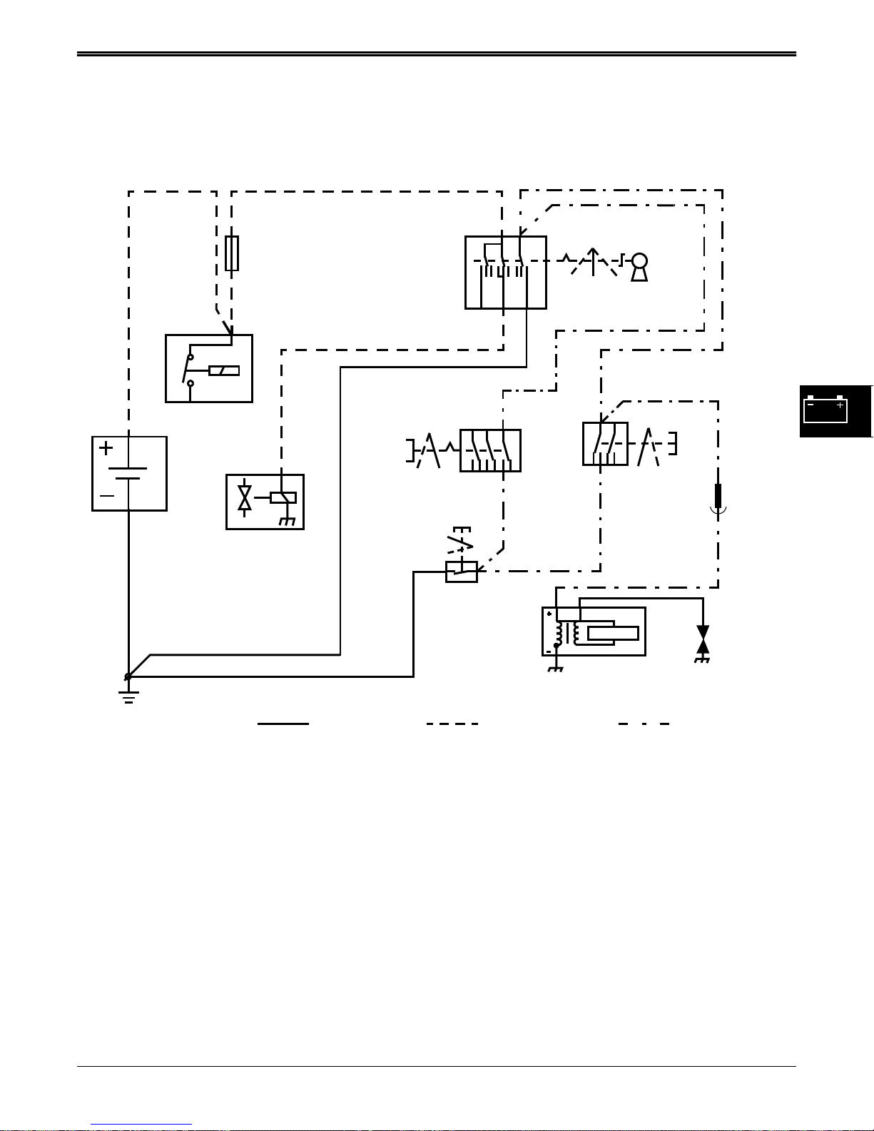
The theory of operation stories divide the electrical
system into individual circuits by function. Each circuit
is isolated from the main wiring schematic and only
shows the components that are used in it. The story
contains information on function, operating conditions,
and theory of operation. The circuit schematics are
drawn with the components in the operating position,
with the power, or battery positive, into them across the
top and the ground, or battery negative, across the
bottom.
DIAGNOSTIC INFORMATION
The diagnostic procedures is used to test the complete
circuit regardless of the problem or complaint. Select a
symptom or system from the quick check or
troubleshooting chart and follow the test procedures
under that heading.
The diagnostic procedure lists:
• Test conditions
• Test sequence
• Test location
• Normal reading
• Check or test to perform if reading is not normal
When performing the test or check, be sure to set your
machine up to the test conditions listed and follow the
sequence carefully. The middle “NORMAL” column
gives the reading or condition that should be obtained
when performing the test or check. If the results of the
test or check are not normal, perform the test, check, or
adjustment listed in the third “IF NOT NORMAL”
column to repair the malfunction. The detailed tests or
adjustments referred to in the “IF NOT NORMAL”
column are located at the end of that group. The
system diagram that accompanies each test procedure
is drawn to resemble machine components. The key
number on the art matches the number in the “TEST
LOCATION” column and the leader line points to the
exact point the test is to be made.
WIRE COLOR ABBREVIATION
CHART
Blk . . . . . . . . . . . . . . . . . . . . . . . . . . . . . . . . . . Black
Blu . . . . . . . . . . . . . . . . . . . . . . . . . . . . . . . . . . .Blue
Brn . . . . . . . . . . . . . . . . . . . . . . . . . . . . . . . . . Brown
Grn . . . . . . . . . . . . . . . . . . . . . . . . . . . . . . . . . Green
Gry . . . . . . . . . . . . . . . . . . . . . . . . . . . . . . . . . . Gray
Org . . . . . . . . . . . . . . . . . . . . . . . . . . . . . . . . Orange
Pnk. . . . . . . . . . . . . . . . . . . . . . . . . . . . . . . . . . . Pink
Pur . . . . . . . . . . . . . . . . . . . . . . . . . . . . . . . . . Purple
Red. . . . . . . . . . . . . . . . . . . . . . . . . . . . . . . . . . . Red
Tan . . . . . . . . . . . . . . . . . . . . . . . . . . . . . . . . . . . Tan
Wht. . . . . . . . . . . . . . . . . . . . . . . . . . . . . . . . . .White
Yel . . . . . . . . . . . . . . . . . . . . . . . . . . . . . . . . . Yellow
Blk/Wht. . . . . . . . . . . . . . . . . . . . . . . . . .Black/White
Blu/Wht. . . . . . . . . . . . . . . . . . . . . . . . . . Blue/White
Brn/Wht . . . . . . . . . . . . . . . . . . . . . . . . Brown/White
Brn/Yel . . . . . . . . . . . . . . . . . . . . . . . . Brown/Yellow
Dk Blu. . . . . . . . . . . . . . . . . . . . . . . . . . . . Dark Blue
Dk Brn/Lt Grn . . . . . . . . . . Dark Brown/Light Green
Dk Brn/Red. . . . . . . . . . . . . . . . . . Dark Brown/Red
Dk Brn/Yel . . . . . . . . . . . . . . . . . Dark Brown/Yellow
Dk Grn . . . . . . . . . . . . . . . . . . . . . . . . . Dark Green
Lt Blue . . . . . . . . . . . . . . . . . . . . . . . . . . . Light Blue
Lt Grn . . . . . . . . . . . . . . . . . . . . . . . . . . Light Green
Org/Wht . . . . . . . . . . . . . . . . . . . . . . . Orange/White
Pnk/Blk . . . . . . . . . . . . . . . . . . . . . . . . . . Pink/Black
READING SCHEMATICS
The schematic is made up of individual circuits laid out
in a sequence of related functions. Current flow is
generally from top to bottom through each circuit and
component. All components are shown in the OFF
position. The diagram does not list connector
information unless needed to avoid confusion.
Each component is shown by a symbol and name. The
identification code contains a device identifying letter
and number.
The circuit number and wire color of the wires are
shown directly next to the wire path.
4 - 4 3/5/97
www.servicemanualall.com
Pur/Wht . . . . . . . . . . . . . . . . . . . . . . . . Purple/White
Red/Blk. . . . . . . . . . . . . . . . . . . . . . . . . . . Red/Black
Red/Wht . . . . . . . . . . . . . . . . . . . . . . . . . . Red/White
Wht/Blk. . . . . . . . . . . . . . . . . . . . . . . . . .White/Black
Wht/Red . . . . . . . . . . . . . . . . . . . . . . . . . . White/Red
Yel/Blk . . . . . . . . . . . . . . . . . . . . . . . . . Yellow/Black
Yel/Red. . . . . . . . . . . . . . . . . . . . . . . . . . Yellow/Red
Yel/Wht . . . . . . . . . . . . . . . . . . . . . . . . . Yellow/White
Page 28

ELECTRICAL SCHEMATIC ELECTRICAL
ELECTRICAL SCHEMATIC
120 BLK
ENGINE
CONNECTOR
SPARK
PLUG
HEADLAMP
HARNESS
HEADLIGHTS
CONNECTOR
940 WHT
0 = OFF
1 = ON
942 WHT
705 PUR/WHT
941 WHT
941A WHT
0 = OFF
1 = ON
SWITCH
IGNITION
10
SWITCH
BRAKE
IGNITION
MODULE
COIL
WHT/BLK
945 WHT/BLK
946A
0
1
BLADE
DRIVE
SWITCH
700 PUR
0 = OFF
1 = RUN02 = START
2 1
0,1
946 WHT/BLK
SEAT
1
0
710 PUR
0 = OFF SEAT
1 = ON SEAT
100 BLK
SWITCH
110 BLK
200 RED
451 YEL/WHT
220 RED/BLK
201 RED
RED/WHT
202
15A
FUSE
201 RED
START
SOLENOID
ENGINE
CONNECTOR
401 YEL
DIODE
RED
BATTERY
M
FUEL
SHUT-OFF
SOLENOID
G
STARTER
MOTOR
(16 HP ONLY)
STATOR
710 PUR
105 BLK
FRAME GROUND
3/5/97 4 - 5
www.servicemanualall.com
Page 29

WIRE HARNESS ELECTRICAL
WIRE HARNESS
945 WHT
942 WHT/BLK
705 PUR
710 PUR/WHT
D
E
451 YEL/WHT
BLADE
DRIVE
SWITCH
R
1
0
2
ENGINE
220RED/BLK
BATTERY
GROUND
CONNECTOR
8mm (5/16") Eyelet
100
110
105
401YEL
FUEL SOLENOID
3
945
946
946A
940 WHT
0
2
1
941
941A
K
L
B
940
942
202RED/WHT
B
ENGINE GROUND
HEADLIGHTS
A
8mm (5/16") Eyelet
451YEL/WHT
B
A
201 RED
120 BLK
946A WHT/BLK
700 PUR
941A WHT
705PUR/WHT
BRAKE SWITCH
Eyelet
8mm (5/16")
BATTERY POSITIVE
SOLENOID
POSITIVE
1 2
R
U
P
0
1
7
220
202
200
100 BLK
401YEL
IGNITION SWITCH
5
10
SOLENOID
GROUND
K
BL
200 RED
15 AMP FUSE
& HOLDER
946 WHT/BLK
SEAT SWITCH
110 BLK
HEADLIGHT
WIRE HARNESS
4 - 6 3/5/97
www.servicemanualall.com
700 PUR
941 WHT
Page 30

COMPONENT LOCATION ELECTRICAL
COMPONENT LOCATION
Headlights
Spark Plug
Starter Motor
Fuel Shut-Off
Solenoid
Seat Switch
Ignition Switch
Blade
Drive
Switch
Brake
Switch
Starter Solenoid
Battery
3/5/97 4 - 7
www.servicemanualall.com
Page 31
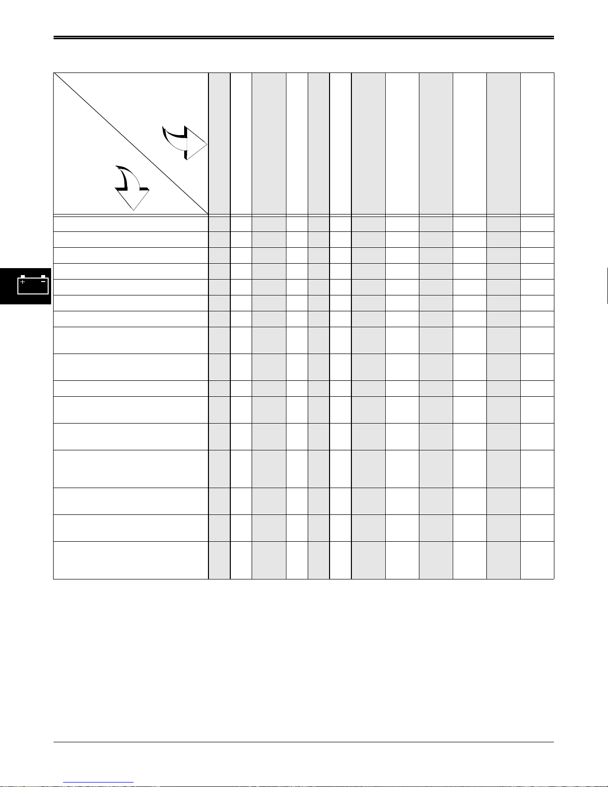
TROUBLESHOOTING ELECTRICAL
TROUBLESHOOTING
Problem or
Symptom
Check or
Solution
Engine will not crank.
Engine cranks—will not start.
Engine starts hard or will not
stay running.
Engine misses or runs rough.
Weak or no spark.
Engine will not shut off.
Battery goes dead,
discharges or overcharges.
Headlights do not light or will
not shut off.
Fuel shut-off solenoid will
not open (16 hp only)
Fuel shut-off solenoid will
not close (16 hp only)
Engine dies when brake lever
is released.
Engine dies when blade lever
is engaged.
See Cranking Circuit Diagnosis ● ● ●●
See Ground Circuit Tests ●● ● ●● ●●● ●●
Test battery and connections.
See Ignition Circuit Tests
See Charging Circuit Tests
See Starter Solenoid Test ●
See Seat Switch Tests ● ● ●●
See headlight circuit test
points.
See fuel shut-off solenoid
circuit test points (16 hp only)
Check for short circuit. ●● ● ●● ●●●●●●
Check for high resistance or
open circuit.
Check for correct spark plug
and spark plug gap.
Check strength of flywheel
ignition module magnet and/or
flywheel stator magnets.
See fuel and air system tests
and adjustments.
Check for stator shorted to
ground
Check seat switch connector is
plugged in and interlock spring
inside connector is good
● ●●●
● ●●●● ●●
● ● ●●
●
● ● ●●
●● ● ●● ●●●●●●
● ●●●
● ●●● ●
● ●●
● ●
●●
4 - 8 3/5/97
www.servicemanualall.com
Page 32
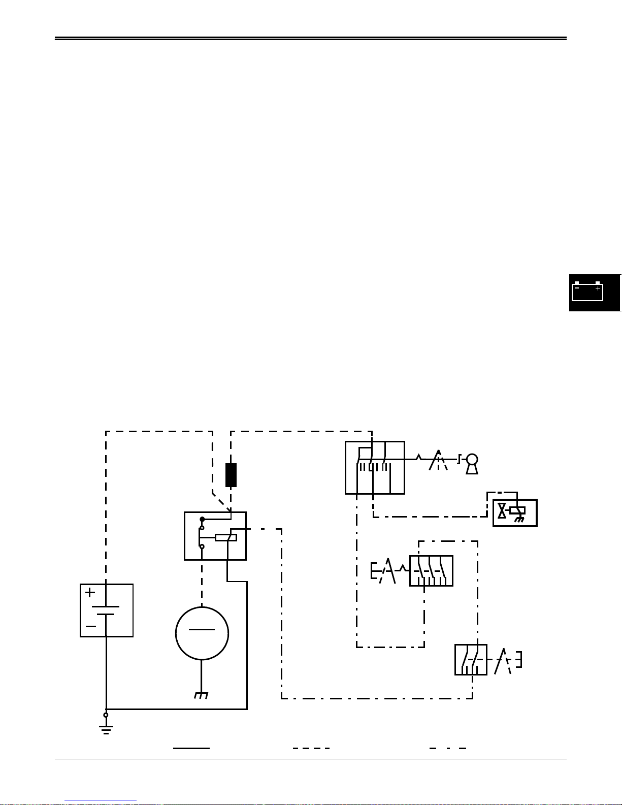
DIAGNOSTICS ELECTRICAL
DIAGNOSTICS
CRANKING & FUEL SHUTOFF
SOLENOID CIRCUIT OPERATION
Function:
The cranking system is used to energize the starting
motor.
Operating Conditions:
In order to crank the engine; the blade drive lever must
be disengaged (blade switch plunger depressed), the
brake pedal must be depressed (brake switch plunger
depressed), and the ignition switch must be in the start
position. The operator does not have to be on the seat
to crank the engine if the above conditions are met.
Theory of Operation:
The starting motor has a separate starter solenoid,
located under the operator’s seat. Current flows from
the battery positive terminal to the starter solenoid
secondary terminal, plug in fuse, and ignition switch.
With the ignition switch in the start position, current
flows from the ignition switch, to the blade drive switch,
brake switch, and to the starter solenoid primary
terminal, energizing the pull-in windings of the solenoid
and engaging the starter.
201 RED
200 RED
The 16 HP fuel shut-off solenoid is also energized by
the ignition switch and allows fuel to flow to the
carburetor.
The blade drive switch is located under the left side of
the mower frame, at the end of the blade drive lever
shaft. It is used to prevent the engine from cranking if
the blade drive is engaged. With the blade drive lever
disengaged, (blade drive switch plunger depressed),
current flows through the 705 Pur/Wht wire to the brake
switch.
The brake switch is located under the right side of the
mower frame, in front of the brake pedal bell crank.
When the park brake is engaged, the bell crank
depresses the brake switch plunger and the switch is
closed, energizing the starter solenoid primary coil.
The starter solenoid plunger is pulled in by the primary
coil, closing the secondary terminals and supplying
high battery current to the starter motor. The spinning
of the starter motor extends the starter bendix drive
into the engine flywheel, turning over the engine until
the ignition circuit fires.
Once the engine starts, the operator releases the
ignition switch to run position. The current flow to the
starter solenoid primary coil is stopped, releasing the
starter solenoid plunger, and cutting off the high battery
current to the starter motor.
STARTER
SOLENOID
BATTERY
STARTER
BLK
MOTOR
FRAME GROUND
RED
M
105 BLK
PLUG-IN
FUSE
IGNITION
SWITCH
1
0=OFF
1=ON
700 PUR
710 PUR
0
401 YEL
705 PUR/WHT
BLADE
DRIVE
SWITCH
BRAKE
SWITCH
0=OFF
1=RUN
012
2=START
FUEL
SHUT-OFF
SOLENOID
0
1
0=OFF
1=ON
GROUND POWER CONTROL
3/5/97 4 - 9
www.servicemanualall.com
Page 33
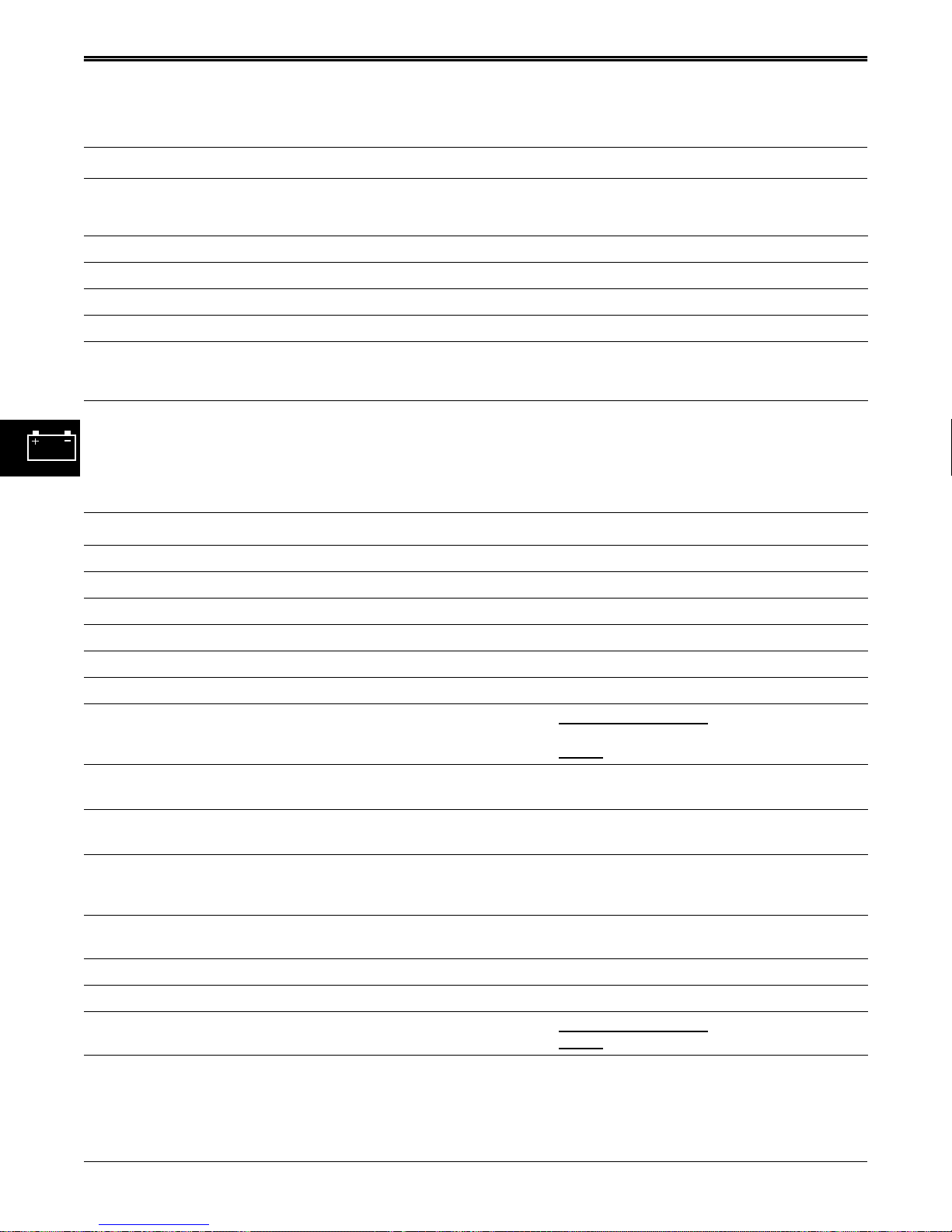
DIAGNOSTICS ELECTRICAL
CRANKING & FUEL SHUTOFF SOLENOID CIRCUIT DIAGNOSIS
Test Conditions:
• Ignition switch in OFF position • Meter positive (+) lead on numbered test point
Test/Check Point Normal If Not Normal
1. Battery positive terminal 11.8-13.2 volts Test battery
2. Starter solenoid front cable terminal Battery voltage Check positive battery cable
3. Plug in fuse under operator’s seat Battery voltage Check fuse and red/wht ignition wires
4. Ignition switch terminal red wire Battery voltage Check red ignition wires
Test Conditions:
NOTE: Perform the tests below one at a time, allowing the starter to cool between tests. Do not allow the starter
to crank for more that 15 seconds, and allow 30 seconds for starter windings to cool. If starter mechanism
is not turning, windings may still be conducting current and heating up. Disconnect starter cable from
starter (and isolate cable terminal) if cranking circuit or fuel shutoff solenoid (and not starter) is being
tested.
Test/Check Point Normal If Not Normal
5. Ignition switch terminal purple wire Battery voltage Replace ignition switch
• Meter negative (—) lead on battery negative (—) terminal
• Blade Drive OFF • Transmission in neutral
• Park brake engaged • Ignition switch in START position
6. Blade Drive Switch purple wire Battery voltage Test purple wire back to ignition switch
7. Blade Drive Switch purple/white wire Battery voltage Check Blade Drive Switch and lever
8. Park brake switch purple/white wire Battery voltage Test purple/white wire back to blade switch
9. Park brake switch purple wire Battery voltage Check park brake switch and lever
10. Starter solenoid purple wire Battery voltage Test purple wire back to park brake switch
11. Starter solenoid ground terminal
(black wire)
12. Starter solenoid battery terminal
(red wire, rear terminal)
13. Starter solenoid starter terminal
(red wire, front terminal)
14. Starting motor Battery voltage Clean battery terminals.
Fuel Shutoff Solenoid Test:
(16 hp only)
15. Ignition switch yellow wire Battery voltage Replace ignition switch
16. Fuel shut-off solenoid yellow wire Battery voltage Check yellow wire back to ignition switch
17. Fuel shut-off solenoid black wire Greater than 0 volts
Greater than 0 volts
Less than 0.2 volts
Battery voltage Clean terminals at battery and solenoid
Battery voltage Clean battery terminals.
(Ignition Switch In Start Position)
Less than 0.2 volts
Greater than 0.2 volts
solenoid ground circuit black wire.
volts - replace solenoid
0
Test red battery wire for shorts or breaks.
Replace starter solenoid
Check red wire back to solenoid.
Test starter (see engine manual)
Greater than 0.2 volts
volts: replace fuel shut-off solenoid
0
- check starter
: check engine ground
4 - 10 3/5/97
www.servicemanualall.com
Page 34
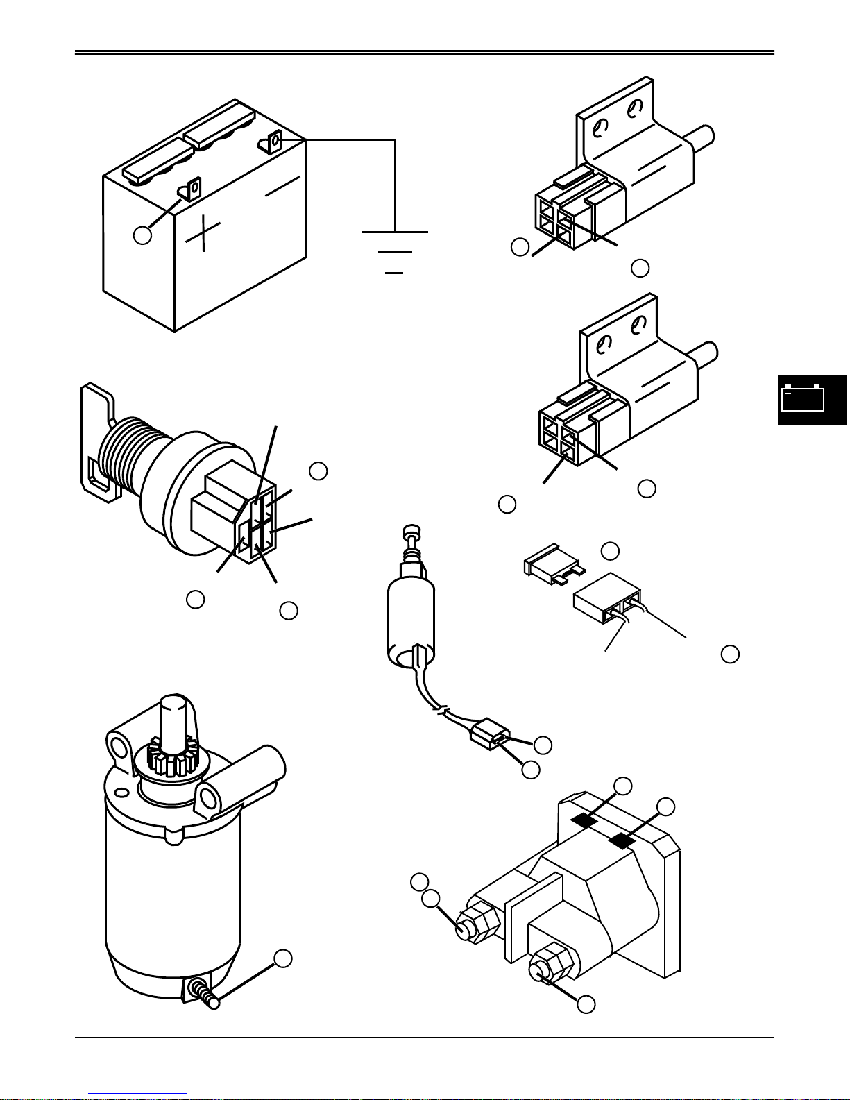
DIAGNOSTICS ELECTRICAL
Blk
IGNITION
SWITCH
1
Red
700 PUR
5
BATTERY
941 WHT
200 RED
16
401 YEL
4
100 Black
8
705 PUR/WHT
705 PUR/WHT
7
700 PUR
710 PUR
15A Fuse
3
9
6
BRAKE
SWITCH
BLADE
DRIVE
SWITCH
STARTER
14
Red
FUEL
SHUTOFF
SOLENOID
201 RED
16
401 YEL
17
BLK
2
12
STARTER RELAY (SOLENOID)
13
710 PUR
10
202 RED/WHT
11
105 BLK
3
3/5/97 4 - 11
www.servicemanualall.com
Page 35
ELECTRICAL DIAGNOSTICS
IGNITION & SEAT SWITCH CIRCUIT
OPERATION
Function:
To create a spark that ignites the fuel/air mixture in the
engine. The ignition coil and module will produce a
spark at the spark plug unless the ignition & seat switch
circuit of the tractor chassis wiring acts to ground the
coil primary and stop the engine.
This circuit is used as a safety interlock to prevent the
engine from starting, or to stop the engine while
running, if the operator attempts to use unsafe actions.
This circuit is independent of the cranking circuit, but
shares some components.
Operating Conditions:
To produce a spark the following conditions must be
met:
• The ignition switch must be in the start or run
position.
• The blade drive lever must be disengaged (back) if
the operator is off the operator’s seat.
• The park brake switch must be engaged (brake
applied) if the operator is off the operator’s seat.
Once the engine is running, the operator must be ON
the seat to release the brake pedal, or engage the
Blade Drive, or the ignition module will be grounded
and the engine will stop.
Theory of Operation:
The ignition system is an electronic magneto design.
Ignition timing is controlled by the ignition module and
is NOT ADJUSTABLE.
Battery current is always present at ignition switch
terminal “B”. When the fuel shut-off solenoid (16
Horsepower engine only) is installed, it becomes
energized when the ignition switch is in either START
or RUN position, via ignition switch terminal “A”,
unseating the plunger and allowing fuel flow into the
venturi of the carburetor. When the ignition switch is
turned OFF, current flow is broken and internal spring
force closes the solenoid plunger, stopping fuel flow.
As the electric starter turns the flywheel, a magnet in
the flywheel produces current in the primary coil of the
ignition module by electromagnetic induction. When
the primary current builds to its highest level, the
ignition module induces high voltage current into the
secondary coil. This high voltage current then flows to
the spark plug and jumps the spark plug gap and
creates a spark that ignites the fuel/air mixture, causing
the engine to start and run.
The ignition module will stop producing current to the
spark plug if the 940 White wire from the coil is allowed
to ground to the mower chassis. The engine is shut off
by grounding the ignition module in one of two ways:
1. Through the ignition switch when key is moved to
OFF position.
2. Through the brake switch, or blade drive switch, if
the operator tries to get OFF the seat with the
blade drive ENGAGED or the park brake NOT
ENGAGED.
When the brake pedal is RELEASED, the brake switch
creates a path for the ignition module to the seat
switch. When the operator is OFF the seat, the seat
switch (normally closed) completes the path to ground
for the ignition module current, preventing high current
induction into the secondary coil which prevents the
spark plug from firing, killing the engine.
The blade drive switch is in parallel with the blade
switch, and will also ground the ignition module when
the blade drive is engaged with no operator on the
machine, killing the engine.
The blade drive and brake switches are also used to
prevent the engine from cranking if the blade drive
lever is ENGAGED or park Brake is NOT ENGAGED
when ignition switch is moved to START. (See
Cranking Circuit Operation Section)
The operator’s seat switch has an interlock built into it’s
connector which prevents the mower from being used
with the seat switch disconnected. An internal spring
will short the two cavity connectors together when
disconnected from the seat switch. This has the effect
of grounding the ignition module when the blade drive
lever is engaged or the brake pedal is released, stalling
the engine.
4 - 12 3/5/97
www.servicemanualall.com
Page 36
DIAGNOSTICS ELECTRICAL
RED
STARTER
SOLENOID
BATTERY
BLACK
RED
201 Orange
401
YELLOW
FUEL
SHUT-OFF
SOLENOID
(OPTIONAL)
100
BLACK
200 RED
401 YELLOW
BLADE
DRIVE
SWITCH
0=OFF
1=ON
1
SEAT
SWITCH
0
0
1
0=OFF
1=ON
M
B
G
A
ST
946
WHITE/
BLACK
945 WHITE/BLACK
942 WHITE
941 WHITE
KEY SWITCH
2
941 WHITE
01
942 WHITE
1
BRAKE
SWITCH
940 WHITE
0=OFF
1=RUN
2=START
940 WHITE
0=OFF
1=ON
0
ENGINE
CONNECTOR
FRAME GROUND
GROUND POWER CONTROL
100 BLACK
110 BLACK
COIL
E1 SPARK
PLUG
IGNITION
MODULE
3/5/97 4 - 13
www.servicemanualall.com
Page 37
DIAGNOSTICS ELECTRICAL
IGNITION CIRCUIT TEST POINTS
When diagnosing an ignition problem, isolate magneto circuit from ground circuit by separating engine connector. If
engine will not start check magneto circuit first and then check ground circuit. If engine will not shut off, check
ground circuit. Remember engine is stopped by grounding ignition coil through either key switch, seat switch or the
brake switch and PTO switch.
Test Conditions:
• Ignition switch in run position • Park Brake engaged • Blade Drive Lever disengaged
• Meter positive (+) lead on
numbered test point
Test/Check Point Normal If Not Normal
1. Engine connector 940 white
wire (wiring harness side of
connector)
Test Conditions:
• Park brake disengaged • Seat switch depressed
Test/Check Point Normal If Not Normal
2. Engine connector 940 white
wire
• Meter negative (—) lead on
engine ground
Infinite resistance Check that blade drive switch
Infinite resistance Check that brake switch is being
Infinite resistance Check for shorted 940, 941, 942,
Infinite resistance Check for faulty ignition switch
Infinite resistance Check for shorted 945/946 white/
• Engine connector disconnected
plunger is being fully depressed by
blade drive lever
fully depressed by brake arm
white wires to chassis
(internal short)
black wires
Check for faulty seat switch
Test Conditions:
• Key switch in off position • Seat switch released • Brake switch released
Test/Check Point Normal If Not Normal
3. Engine connector 940 white
wire
Maximum 0.1 ohms Check for open 940/941/942 white
wires
Check for open 100/110 black wires
4 - 14 3/5/97
www.servicemanualall.com
Page 38
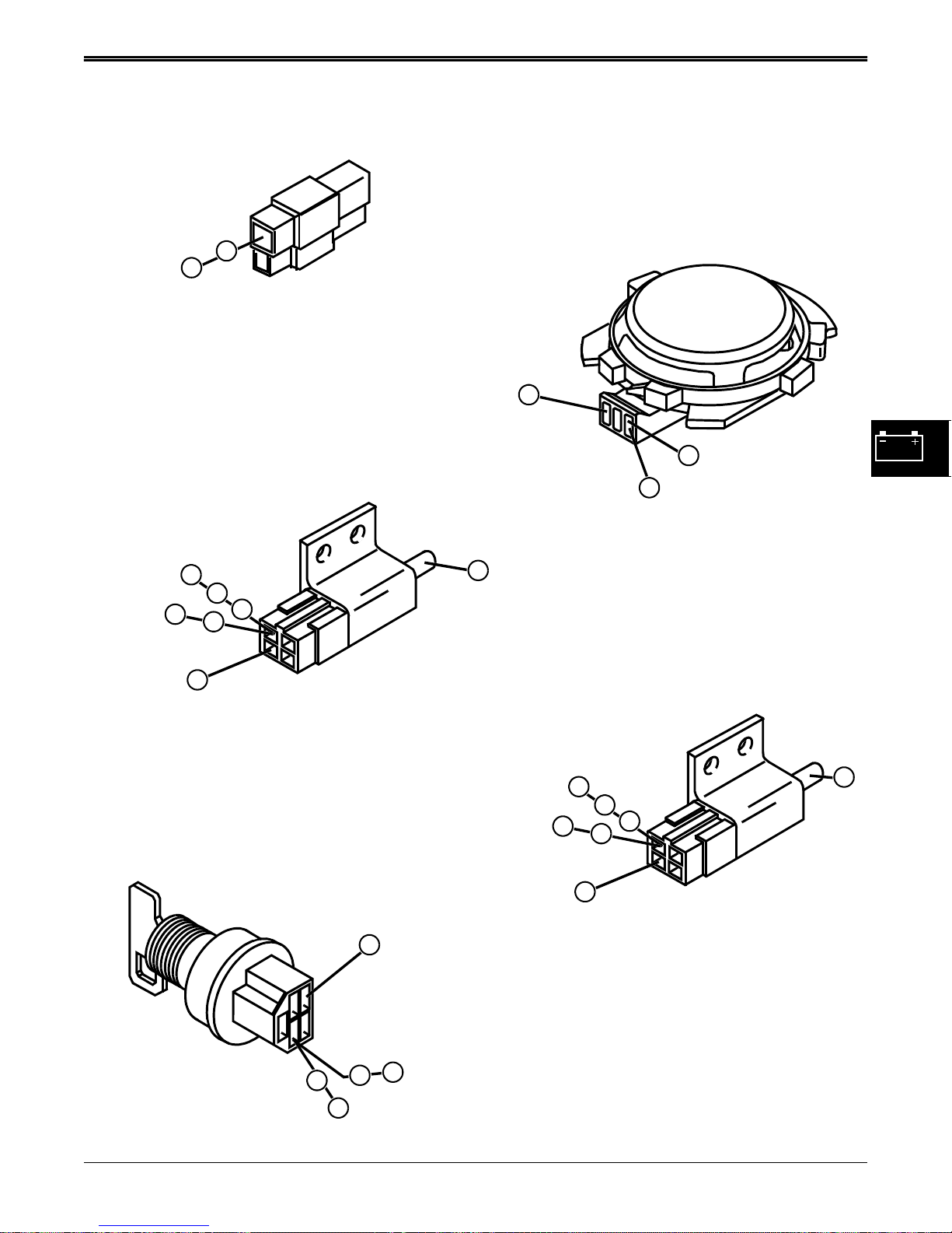
DIAGNOSTICS ELECTRICAL
940
White
940
White
942
White
White/Black
945
2
1
Engine
Connector
110
Black
3
Seat Switch
S4
2
945
White/Black
2
946
White/Black
1
2
1
3
3
2
Brake Switch
1
Key Switch
3/5/97 4 - 15
www.servicemanualall.com
3
1
White
3
3
941
100
Black
1
942
White
940
White
942
1
1
White
945
White/Black
1
2
3
3
2
Blade Drive Switch
Page 39
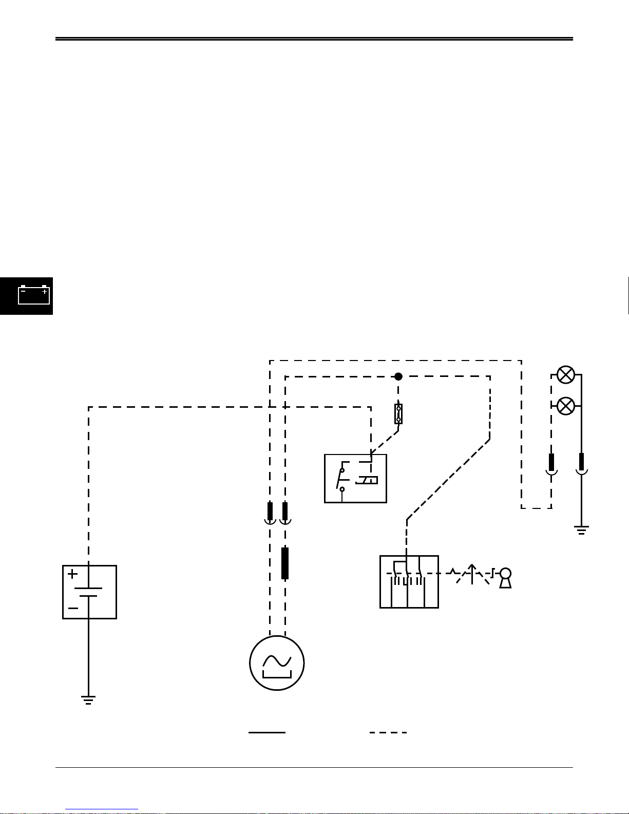
ELECTRICAL DIAGNOSTICS
CHARGING & HEADLIGHT CIRCUIT
OPERATION
Function:
To maintain battery voltage between 11.8 and 13.2.
Operating Conditions:
The engine must be running for the charging system to
operate. Headlights are on only when the engine is
running.
451 YEL/WHT
Theory of Operation:
The charging system is of the permanent magnet and
stator design. Magnets imbedded into the crankshaft
flywheel pass a multi-pole stator mounted under the
flywheel, inducing alternating current into the stator
coils. Alternating current is routed to the headlamp
bulbs anytime the engine is running through the 451
Yel/Wht wire. One half of the stator output current is
rectified by an in-line diode in the 220 Red/Blk circuit,
and used to charge the battery. Charging output is unregulated.
HEADLIGHTS
220 RED
200 RED
BATTERY
BLACK
201 RED
CONNECTOR
ENGINE
G
DIODE
STARTER
SOLENOID
15 A FUSE
201 RED
ST
120 BLACK
M
B
A
IGNITION SWITCH
G
0=OFF
1=RUN
2=START
012
W1 FRAME GROUND
4 - 16 3/5/97
www.servicemanualall.com
STATOR
GROUND POWER
Page 40
DIAGNOSTICS ELECTRICAL
CHARGING CIRCUIT DIAGNOSIS
Test Conditions:
• Brake engaged, blade drive lever disengaged • Engine running at fast idle (3600 rpm)
• Engine connector disconnected • Meter negative (–) lead on battery negative (–) terminal
• Ignition switch in run position • Meter positive (+) lead on numbered test point
NOTE: Be sure to set multimeter to read AC or DC voltage or amperage as test requires:
Test/Check Point Normal If Not Normal
1. Engine connector 451 Yel/Blk
wire
2. Engine connector 220 Red/Blk
wire
3. Headlamps Remain on with engine running Go to step 4
4. Headlamp connector 451 Yel/
Wht connector at engine cover
Test Conditions:
• Meter negative (—) lead grounded to engine frame • Stop engine
• Meter positive (+) lead on numbered test point • Disconnect engine connector
Test/Check Point Normal If Not Normal
5. Engine connector wires:
Red Wire
Black wire
Unregulated voltage 14 VAC See Briggs & Stratton engine
manual for charging system repair
2–4 Amps DC See Briggs & Stratton engine
manual for charging system repair
11.8-13.2 DC voltage
Check headlamp bulbs
Infinite resistance from wire to ground
Infinite resistance from wire to wire
See Briggs & Stratton engine
manual for charging system repair
Check stator for short to ground
Check stator for internal short
See Briggs & Stratton manual
Test Conditions:
• Reconnect engine connector • Start engine • Multimeter negative to ground
Test/Check Point
6. Plug in fuse 11.8-13.2 DC volts (both sides of fuse) Check 220 Red/Blk circuit
7. Red wire at ignition switch 11.8-13.2 DC volts Check 220 Red circuit
8. Battery positive terminal 11.8-13.2 DC volts Check 201 Red Battery Positive
3/5/97 4 - 17
www.servicemanualall.com
lead and terminal connector
Page 41
DIAGNOSTICS ELECTRICAL
HEADLIGHTS CIRCUIT DIAGNOSIS
Test Conditions:
• Park brake engaged, blade drive disengaged • Engine running at fast idle
• Meter negative (—) lead on battery negative (—)
terminal
NOTE: But sure to set multi-meter to measure AC or DC voltage or amperage as required by test:
Test/Check Point Normal If Not Normal
1. Headlamps Bulbs are lit whenever engine is
running
2. Yellow/White wire at
headlamp socket connector
3. Yellow/White wire at
connector at engine cover
hinge.
Test Conditions:
• Stop engine
Test/Check Point
4. Remove engine connector
and test for voltage at Red
wire from engine. See
Charging Circuit Diagnosis
Section in this manual
12—14 Volts AC.
Test ground circuit
12—14 Volts AC.
Replace headlamp harness under
engine cover
12—14 Volts AC See Briggs & Stratton engine
• Meter positive (+) lead on numbered test point
Check for burned out bulbs
Go to step 3
Go to step 4
manual for service and repair
4 - 18 3/5/97
www.servicemanualall.com
Page 42
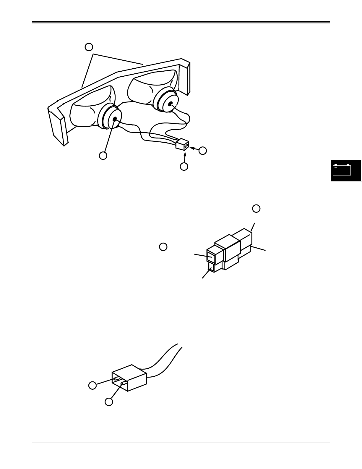
DIAGNOSTICS ELECTRICAL
1
2
Yel/Wht
2
Headlight Harness
3
120 Black
451Yel/Wht
4
Red
TO ENGINE
3
451
Yellow/White
TO CHASSIS
220
Red/Black
451 YEL/WHT
120 Black
5
Engine
Connector
Black
7
3/5/97 4 - 19
www.servicemanualall.com
Headlight Harness
Page 43
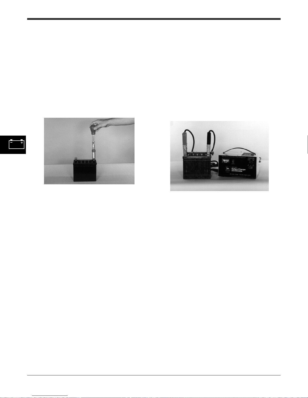
ELECTRICAL TESTS AND ADJUSTMENTS
TESTS AND ADJUSTMENTS
BATTERY TEST
Reason:
To check condition of battery and determine battery
voltage.
Equipment:
• Hydrometer
• Voltmeter or Battery Tester
• All cells more than 1.225 with less than 50 point
variation, load test battery.
• More than 50 point variation: replace battery.
CHARGE BATTERY
Reason:
To increase battery charge after battery has been
discharged.
Equipment:
• Battery charger (variable rate)
Procedure:
1. Clean battery terminals and top of battery.
2. Inspect battery terminals and case for breakage or
cracks.
3. Check electrolyte level in each battery cell. Add
clean, soft water as needed. If water was added,
charge battery for 20 minutes at 10 amps.
4. Remove surface charge by placing a small load on
the battery for 15 seconds.
5. Check specific gravity of each cell with a
hydrometer.
6. Check battery voltage with voltmeter or Battery
Tester.
Specifications:
Minimum specific gravity
. . . . . . . . . 1.225 with less than 50 point variation
Minimum battery voltage. . . . . . . . . . . . . . 12.4 volts
Results:
• Battery voltage less than 12.4 VDC, charge battery.
• Battery voltage more than 12.4 VDC, test specific
gravity.
• All cells less than 1.175, charge battery at 10 amp
rate.
• All cells less than 1.225 with less than 50 point
variation, charge battery at 10 amp rate.
Procedure:
NOTE: See BATTERY TEST in this group before
charging battery.
1. Connect variable rate charger to battery.
NOTE: Maximum charge time at boost setting is 10
minutes. Allow additional 5 minutes for each 10
degrees below 70 degrees F.
2. Start charger at slow rate. Increase charge rate one
setting at a time. Check charger ammeter after 1
minute at each setting. Maintain 10 amp charge
rate. Use boost setting as necessary.
3. Check if battery is accepting a 10 amp charge after
10 minutes at boost setting.
Battery will not accept 10 amp charge after 10
minutes at boost setting: replace battery.
Battery is accepting 10 amp charge after 10 minutes
at boost setting, and battery did not need water:
go to steps 6 and 7.
Battery is accepting 10 amp charge after 10 minutes
at boost setting, but battery did need water or all
cells were below 1.175: go to steps 4 and 5.
4. Set charger at 15-25 amps.
4 - 20 3/5/97
www.servicemanualall.com
Page 44
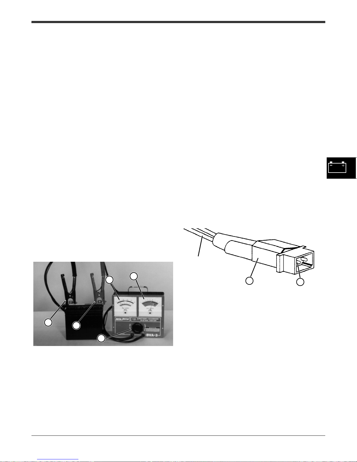
TESTS AND ADJUSTMENTS ELECTRICAL
IMPORTANT: Decrease charge rate if battery gases
or bubbles excessively or becomes too warm to
touch.
5. Check specific gravity after 30 minutes (60 minutes
for maintenance-free battery).
More than 50 point variation between cells: replace
battery.
Less than 50 point variation between cells: go to
steps 6 and 7.
NOTE: If battery was discharged at slow or unknown
rate, charge at 10–15 amps for 6–12 hours.
(Maintenance-free battery: 12–24 hours.)
If battery was discharged at fast rate, charge at
20–25 amps for 2–4 hours.
(Maintenance-free battery: 4–8 hours.)
6. Continue charging battery until specific gravity is
1.230-1.265 points.
7. Load test battery.
BATTERY LOAD TEST
Reason:
To check condition of battery under load.
Procedure:
1. Turn load knob of tester clockwise until amperage
reading (A) is equal to:
a.Cold cranking amperage rating (use blue scale).
— OR —
b.Three times ampere hour rating (use black scale).
2. Hold for 15 seconds and turn load knob of tester off.
3. Repeat procedure steps 1 and 2 from above and
read condition of battery at DC Volts scale (B).
Results:
• If the battery does not pass the test and has not
been charged, charge battery and retest.
• If the battery does not pass the test and has been
charged, replace the battery.
DC AMPERAGE OUTPUT TEST
Reason:
To determine direct current amperage output of the
engine.
Equipment:
• Multimeter
Equipment:
• Battery Tester
A
E
D
C
B
Connections:
1. Turn load knob (C) of tester counter-clockwise to
off.
2. Connect tester positive cable (D) to battery positive
terminal.
3. Connect tester negative cable (E) to battery
negative terminal.
Red Wire
A
B
Connections:
1. Remove surface charge from battery by cranking
engine for 15 seconds.
2. Set multimeter to read DC amperage
3. Disconnect engine connector (A).
4. Connect red multimeter red lead to red wire from
engine connector at terminal (B).
5. Connect black multimeter lead to chassis ground.
Procedure:
1. Start and run engine at 3600 rpm while watching
multimeter.
Specifications:
DC Amperage (Max) . . . . . . . . . . . . . . . . . . . . 2 Amps
Results:
• If engine fails to produce DC amperage, see the
Briggs & Stratton service manual for repair
information.
3/5/97 4 - 21
www.servicemanualall.com
Page 45
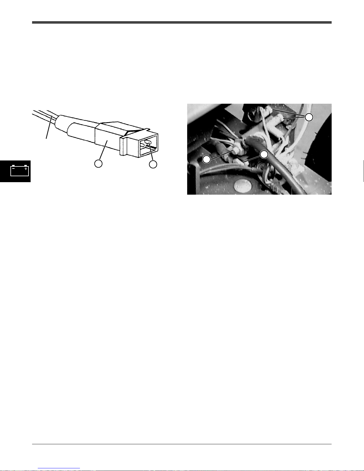
ELECTRICAL TESTS AND ADJUSTMENTS
AC VOLTAGE OUTPUT TEST
Reason:
To measure engine alternating current voltage output to
determine stator condition.
Equipment:
• Multimeter
Black Wire
A
Connections:
1. Disconnect engine connector (A).
2. Set multimeter to read AC voltage.
3. Connect red multimeter lead to black wire from
engine connector at terminal (B).
4. Connect black multimeter lead to chassis ground.
Procedure:
1. Start and run engine at 3600 rpm while watching
multimeter.
B
STARTER SOLENOID TEST
Reason:
To determine if starter solenoid or starter is defective.
Equipment:
• Jumper wire
A
B
C
Connections:
1. Put transaxle in neutral. Move key switch to off
position.
2. Engage park brake.
3. Disconnect and ground spark plug lead.
4. Disconnect purple wire from small starter solenoid
engagement terminals (A).
Specifications:
AC Voltage Output (3600 rpm):. . . . . . . . . . . 14 Volts
Results:
• If reading is less than specifications, see Briggs &
Stratton service manual for electrical system
repair.
Procedure:
1. Connect jumper wire to positive battery terminal
and briefly jump to bare small starter solenoid
engagement terminal (A).
Results:
• Starter runs: solenoid is good, check circuit wiring.
• Starter does not run: go to step 2.
2. Connect jumper wire between starter solenoid large
terminals (B and C).
Results:
• Starter runs: Replace solenoid.
• Starter does not run: Check battery cables then
replace starter.
4 - 22 3/5/97
www.servicemanualall.com
Page 46
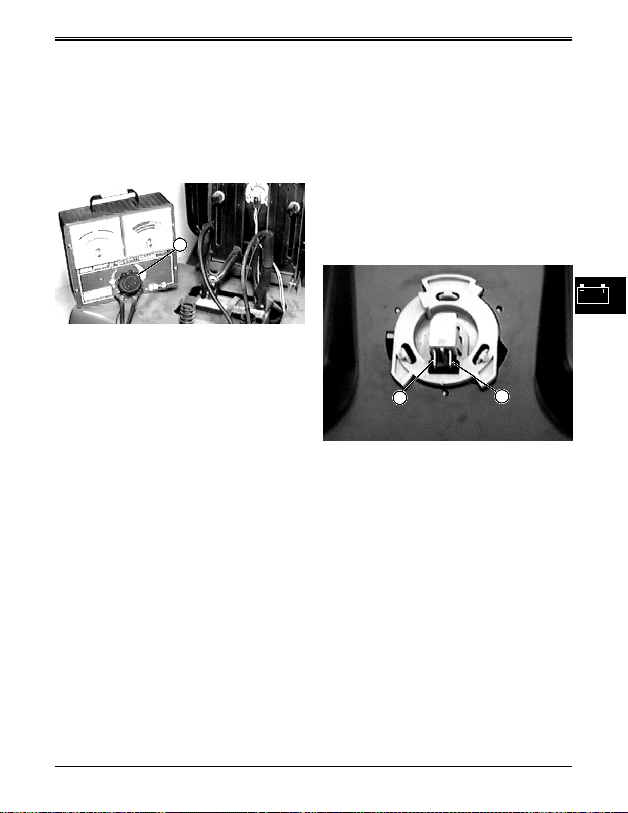
TESTS AND ADJUSTMENTS ELECTRICAL
STARTER AMP DRAW TEST
Reason:
To determine the amperage required to crank the
engine and check starter motor operation under load.
Equipment:
• Battery Tester
• Photo Tachometer
A
Connections:
1. Put transaxle in neutral. Engage park brake.
2. Test system ground connections and battery.
3. Turn knob (A) of tester counter-clockwise to off.
4. Connect red clamp of battery tester to positive
terminal of battery and black clamp of tester to
negative terminal of battery.
5. Install tachometer reflective tape on flywheel
screen.
6. Remove spark plug high tension lead and ground to
engine.
Procedure:
1. Crank engine and read voltage on DC voltage scale
of battery tester and check engine rpm.
2. Turn key switch to off position.
IMPORTANT: Perform the following procedure
within 15 seconds to prevent electrical damage
to components.
SEAT SWITCH TEST
Reason:
To ensure proper operation of seat switch.
Equipment:
• Ohmmeter
Procedure:
1. Park machine on level surface and turn key switch
OFF.
2. Shift lever in NEUTRAL and park brake LOCKED.
3. Disconnect harness connector from seat switch.
A
4. Check continuity across switch terminals (A) and
(B).
Results:
• There should BE continuity between terminals (A
and B) when seat is RELEASED,
• There should NOT BE continuity between terminals
(A and B) when plunger is DEPRESSED.
• If continuity is NOT correct, replace switch.
B
3. Turn knob of battery tester clockwise until the DC
voltage is the same as when cranking.
4. Read DC amperage on battery tester.
5. Turn load knob fully counterclockwise.
Specifications:
Maximum starter amp draw
. . . . . . . . . . . . . . . . . . . . . . . . 180 amps at 225 rpm
Results:
• If amperage is above specification, or rpm is low,
check starter for binding or damaged.
• If starter is good, check internal engine, traction or
PTO drive for binding or damage.
3/5/97 4 - 23
www.servicemanualall.com
NOTE: The seat switch connector has an interlock
spring which shorts the 3 wires together when
removed from seat switch terminals. Check
that spring mechanism is releasing properly
when center tab is depressed.
Page 47
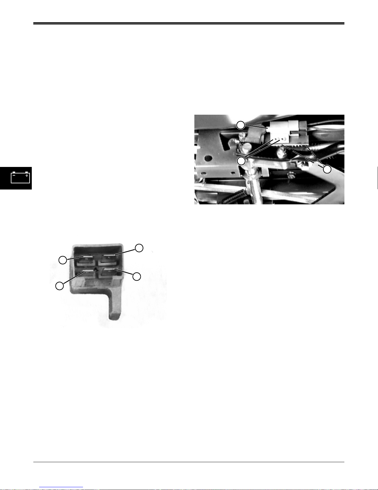
ELECTRICAL TESTS AND ADJUSTMENTS
BRAKE SWITCH / BLADE DRIVE
SWITCH TEST
Reason:
To make sure the brake pedal switch and blade drive
switch operate properly.
Equipment:
• Ohmmeter
Procedure:
1. Park machine on level surface and turn ignition
switch OFF.
2. Shift lever in NEUTRAL and park brake LOCKED.
3. Blade drive DISENGAGED.
4. Locate switch being tested as follows:
Brake switch is located under right side frame at
brake pedal bellcrank.
Blade drive switch is located under left side frame
at bottom of blade drive lever actuating arm.
5. Disconnect harness connector from switch being
tested.
B
A
C
D
6. Check continuity as follows using terminals shown
above.
• there should BE continuity between terminals (B
and C) when plunger is RELEASED,
• there should NOT BE continuity between terminals
(B and C) when plunger is DEPRESSED.
• there should NOT BE continuity between terminals
(A and D) when plunger is RELEASED,
BRAKE SWITCH ADJUSTMENT
Reason:
To ensure proper that engine starts only when brake
fully applied.
Procedure:
1. Depress brake pedal and set park brake.
.
A
C
B
2. Check condition of both mounting rivets (C). If not
tight, damaged, or improperly installed, they could
affect adjustment and function of start and safety
circuits. If rivets are bad, go to Step 3; if rivets are
good, go to Step 4.
3. Disconnect harness connector and remove switch
assembly to bench vise. Remove rivets, as
necessary, using a 4.76 mm (3/16 in.) drill bit and
replace with 4.75 x 14.61 mm (0.187 x 0.575 in.)
aluminum pop rivets (M67899). Loosely install
switch and solidly connect harness connector.
4. Loosen switch bracket hardware (B).
5. Move switch until plunger (A) is about 3 mm (1/8 in.)
from bottoming.
6. Check that switch does not bottom when brake
pedal fully depressed. Increase clearance if
needed.
7. Tighten bracket hardware.
8. Check switch operation.
• Engine should NOT turn over or start when brake
pedal is not depressed.
• Engine should turn over and start when brake pedal
is fully depressed.
• If operation is not correct, test switch.
• there should BE continuity between terminals (A
and D) when plunger is DEPRESSED.
Results:
• If continuity is NOT correct, replace switch.
4 - 24 3/5/97
www.servicemanualall.com
Page 48
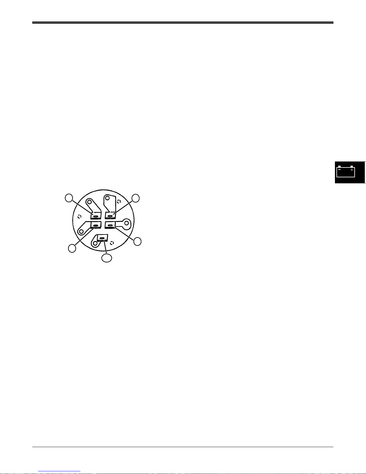
TESTS AND ADJUSTMENTS ELECTRICAL
IGNITION SWITCH TEST
Reason:
To verify ignition switch functions are operating
properly.
Equipment:
• Ohmmeter or Continuity Tester
Procedure:
1. Park machine on level surface and turn ignition
switch OFF.
2. Shift lever in NEUTRAL and park brake LOCKED.
3. Remove ignition switch cover (see Repair Section
page 27 for Ignition Switch Removal & Installation)
4. Disconnect ignition switch connector.
G
B
ST
A
M
NOTE: Ignition switch terminals are identified to
coincide with electrical schematic
designations.
5. Use an ohmmeter to test ignition switch continuity in
OFF, RUN, and START positions.
Ignition Switch Continuity
Switch Position Terminal Continuity
OFF . . . . . . . . . . . . . . . . . . . . . . . . . . . . . . . (G and M)
RUN . . . . . . . . . . . . . . . . . . . . . . . . . . . . . . . (A and B)
START . . . . . . . . . . . . . . . . . . . . . . . (A and B and ST)
Results:
• If any continuity is NOT correct, replace ignition
switch.
3/5/97 4 - 25
www.servicemanualall.com
Page 49
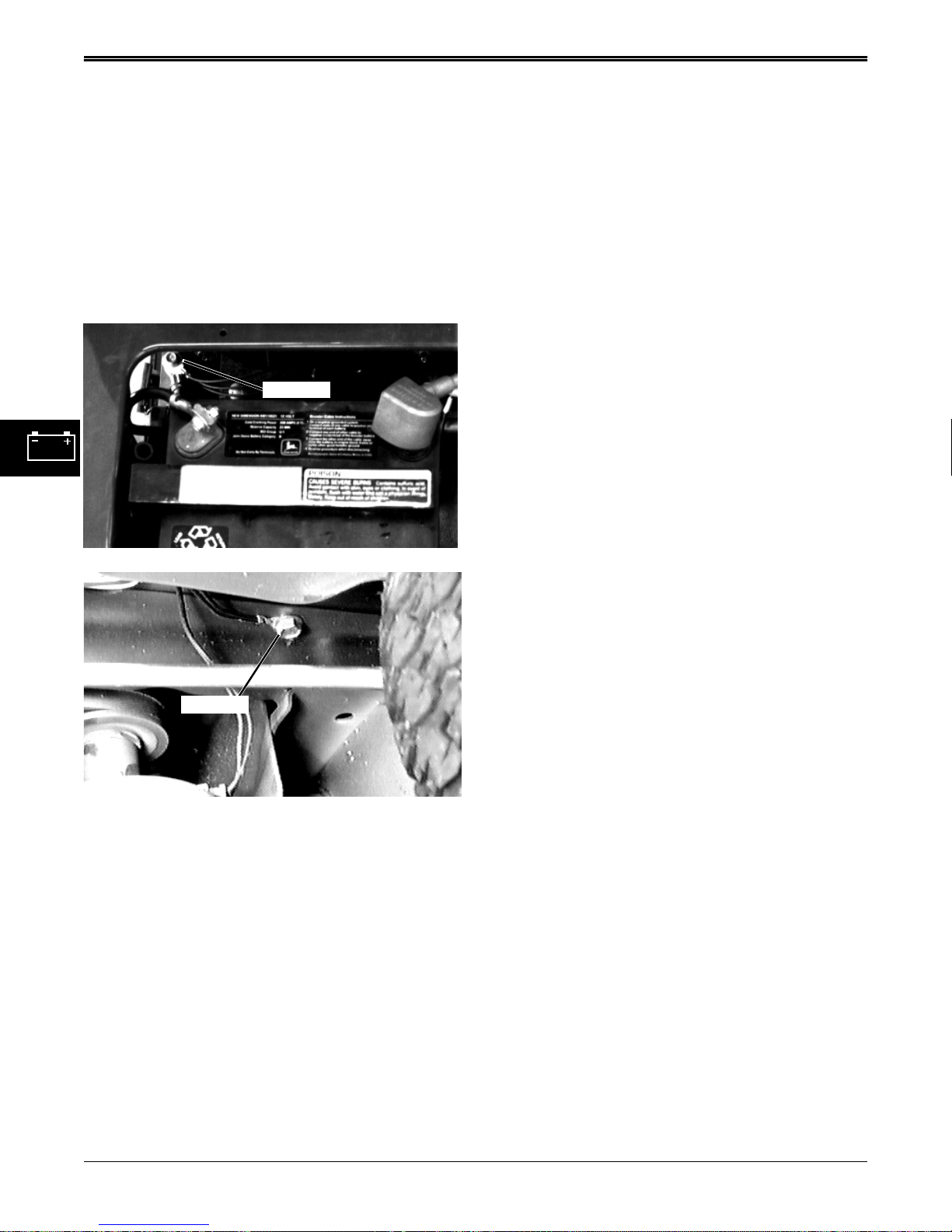
ELECTRICAL TESTS AND ADJUSTMENTS
GROUND CIRCUIT TESTS
Reason:
To check for opens, loose terminal wire crimps, poor
connections, or corrosion in the ground circuit. The
voltmeter method checks ground connections under
load.
Equipment:
• Ohmmeter or voltmeter
GROUND
Chassis Ground
points. If a problem is indicated, disconnect the
wiring harness connector to isolate the wire or
component and check resistance again. Maximum
allowable resistance in the circuit is 0.1 ohms.
Check both sides of connectors closely as
disconnecting and connecting may temporarily
solve problem.
VOLTMETER METHOD:
1. Put transmission in neutral. Engage park brake. Put
blade drive switch in disengaged position. Turn
ignition switch to on position.
2. Connect voltmeter negative (black) lead to negative
terminal of battery.
3. Put meter positive (red) lead on ground terminal of
component to be tested. Be sure the component
circuit is activated (key on, switches closed) so
voltage will be present at the component. Record
voltage. Voltage must be greater than 0 but less
than 1 volt. Some components will have a very
small voltage reading on the ground side and still
be operating correctly.
Results:
• If resistance is above 0.1 ohms, check for open
wiring, loose terminal wire crimps, poor
connections, or corrosion in the ground circuit.
• If voltage is 0, the component is open.
• If voltage is greater than 1 volt, the ground circuit is
bad. Check for open wiring, loose terminal wire
crimps, poor connections, or corrosion in the
ground circuit.
GROUND
Engine Ground
Procedure:
OHMMETER METHOD:
1. Turn ignition switch to off position. Engage park
brake.
2. Connect ohmmeter negative (black) lead to
negative terminal of battery. Put meter positive
(red) lead on negative terminal of battery and
record reading.
3. Put meter red lead on ground terminal of circuit or
component to be tested that is closest to the
battery negative terminal. Resistance reading
must be very close to or the same as the battery
negative terminal reading. Work backwards from
the battery on the ground side of the problem
circuit until the resistance reading increases above
0.1 ohms. The problem is between the last two test
4 - 26 3/5/97
www.servicemanualall.com
Page 50
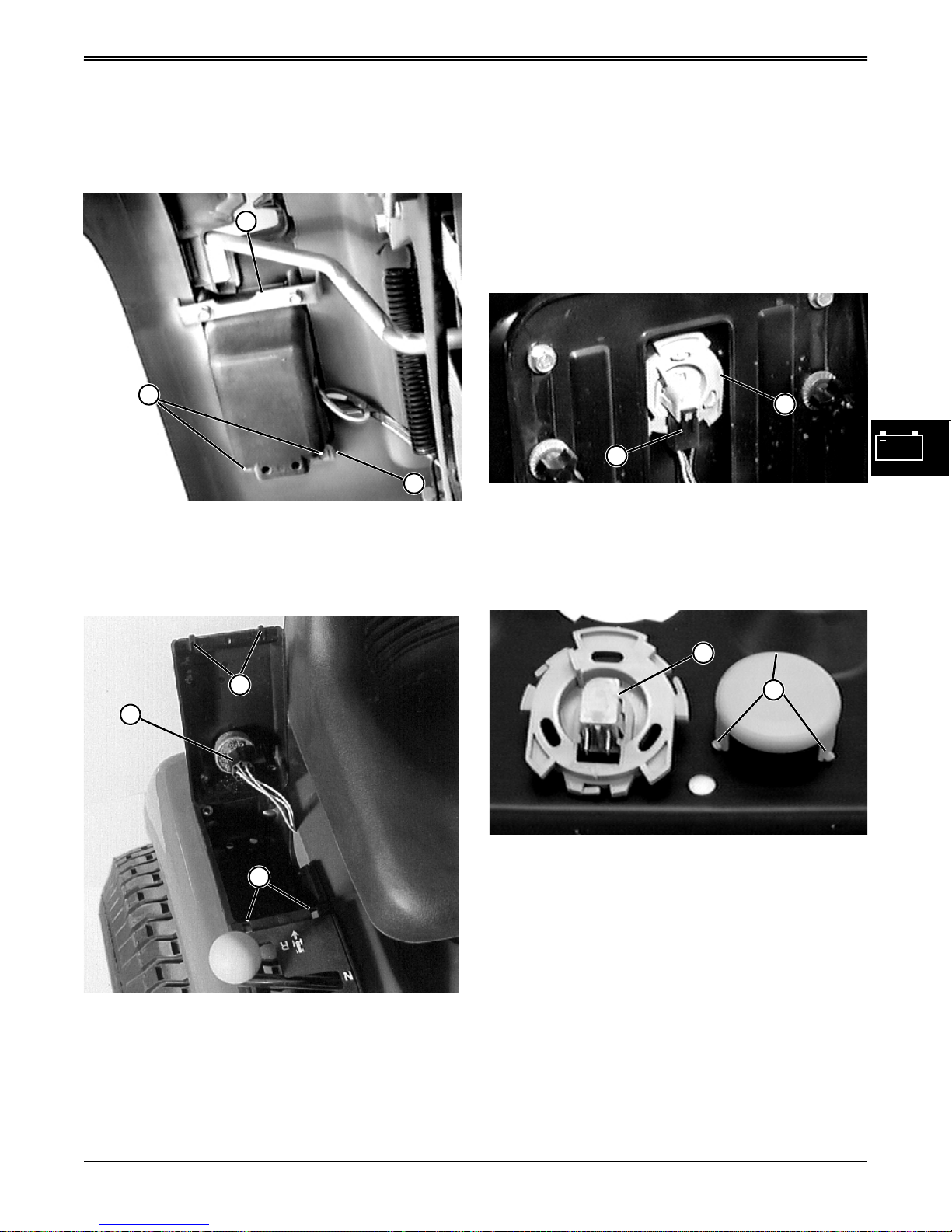
REPAIR ELECTRICAL
REPAIR
IGNITION SWITCH REMOVAL &
INSTALLATION
F
A
B
1. Remove rear retaining screws (A) and Bracket (B).
NOTE: Front bracket (F) does not have to be removed.
SEAT SWITCH REMOVAL &
INSTALLATION
NOTE: Seat switch connector has an internal spring
which will short cavities of connector together
when it is disconnected from seat switch. This
prevents operator from defeating seat switch
by leaving connector disconnected.
B
A
1. Tilt seat forward.
2. Disconnect connector (A).
3. Rotate switch assembly (B) counterclockwise to
remove switch from seat pan.
D
C
E
2. Remove ignition switch connector (C).
3. Check and/or replace ignition switch as required.
4. Install new switch and replace cover by inserting
lugs (D) into slots (E). Secure from underside of
tractor fender with two screws (A) and bracket (B).
DO NOT overtighten screws, they are threaded
into plastic.
C
D
4. Depress tabs (D) of cover and remove.
5. Unsnap switch (C) from housing.
6. Assemble in reverse order of disassembly.
3/5/97 4 - 27
www.servicemanualall.com
Page 51
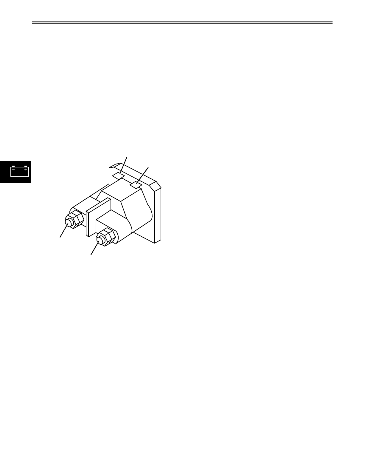
ELECTRICAL REPAIR
STARTER SOLENOID REMOVAL &
INSTALLATION
Procedure:
1. Park machine on level surface, park brake ON,
engine OFF.
2. Lift seat and remove negative battery cable from
battery terminal.
3. Remove positive battery cable from battery
terminal.
4. Remove battery hold-down (rubber strap) from
frame, and lift battery from tractor.
5. Starter solenoid is located under operator’s seat in
front of battery.
710 Purple To Brake Switch
105 Black To Ground
201 Red To Battery
201 Red To Fuse
201 Red To Starter
6. Follow wiring above to remove and replace
solenoid from frame.
7. When connecting battery, always connect positive
cable to battery terminal first, and negative cable
last.
4 - 28 3/5/97
www.servicemanualall.com
Page 52

CONTENTS GEAR POWER TRAIN
CONTENTS
Page
GEAR POWER TRAIN
SPECIFICATIONS. . . . . . . . . . . . . . . . . . . . . . . . . . . . . . . . . . . . . . . . . . . 3
TORQUE SPECIFICATIONS . . . . . . . . . . . . . . . . . . . . . . . . . . . . . . . . . . . . . . . . . . . 4
OTHER MATERIALS. . . . . . . . . . . . . . . . . . . . . . . . . . . . . . . . . . . . . . . . . . . . . . . . . . 4
SERVICE PART KITS . . . . . . . . . . . . . . . . . . . . . . . . . . . . . . . . . . . . . . . . . . . . . . . . . 4
TROUBLESHOOTING . . . . . . . . . . . . . . . . . . . . . . . . . . . . . . . . . . . . . . . 5
COMPONENT LOCATION . . . . . . . . . . . . . . . . . . . . . . . . . . . . . . . . . . . . 6
TRANSAXLE COMPONENT LOCATION . . . . . . . . . . . . . . . . . . . . . . . . . . . . . . . . . . 7
TRACTION DRIVE SYSTEM COMPONENT LOCATION. . . . . . . . . . . . . . . . . . . . . . 8
THEORY OF OPERATION . . . . . . . . . . . . . . . . . . . . . . . . . . . . . . . . . . . 10
TRACTION DRIVE SYSTEM OPERATION . . . . . . . . . . . . . . . . . . . . . . . . . . . . . . . 10
TRANSAXLE OPERATION. . . . . . . . . . . . . . . . . . . . . . . . . . . . . . . . . . . . . . . . . . . . 11
BRAKE SYSTEM OPERATION. . . . . . . . . . . . . . . . . . . . . . . . . . . . . . . . . . . . . . . . . 12
DIAGNOSIS. . . . . . . . . . . . . . . . . . . . . . . . . . . . . . . . . . . . . . . . . . . . . . . 13
TESTS AND ADJUSTMENTS . . . . . . . . . . . . . . . . . . . . . . . . . . . . . . . . 15
CLUTCH/BRAKE LINKAGE &TRACTION DRIVE ADJUSTMENT . . . . . . . . . . . . . . 15
SHIFT LINKAGE ADJUSTMENT. . . . . . . . . . . . . . . . . . . . . . . . . . . . . . . . . . . . . . . . 17
REPAIR. . . . . . . . . . . . . . . . . . . . . . . . . . . . . . . . . . . . . . . . . . . . . . . . . . 18
TRACTION DRIVE BELT REMOVAL . . . . . . . . . . . . . . . . . . . . . . . . . . . . . . . . . . . . 18
TRACTION DRIVE BELT INSPECTION . . . . . . . . . . . . . . . . . . . . . . . . . . . . . . . . . . 19
TRACTION DRIVE BELT INSTALLATION . . . . . . . . . . . . . . . . . . . . . . . . . . . . . . . . 20
TRACTION DRIVE SYSTEM REMOVAL . . . . . . . . . . . . . . . . . . . . . . . . . . . . . . . . . 20
SHIFT LINKAGE REMOVAL & INSTALLATION. . . . . . . . . . . . . . . . . . . . . . . . . . . . 22
TRANSAXLE REMOVAL & INSTALLATION. . . . . . . . . . . . . . . . . . . . . . . . . . . . . . . 23
TRANSAXLE DISASSEMBLY. . . . . . . . . . . . . . . . . . . . . . . . . . . . . . . . . . . . . . . . . . 23
INTERMEDIATE SHAFT & DRIVE SHAFT REPAIR. . . . . . . . . . . . . . . . . . . . . . . . . 29
TRANSAXLE ASSEMBLY. . . . . . . . . . . . . . . . . . . . . . . . . . . . . . . . . . . . . . . . . . . . . 30
3/5/97 5 - 1
www.servicemanualall.com
Page 53

GEAR POWER TRAIN CONTENTS CONTINUED
5 - 2 3/5/97
www.servicemanualall.com
Page 54

SPECIFICATIONS GEAR POWER TRAIN
SPECIFICATIONS
Dimensions:
Overall Axle Width (End-To-End) . . . . . . . . . . . . . . . . . . . . . . . . . . . . 735.4 mm (29 in.)
Overall Case Width . . . . . . . . . . . . . . . . . . . . . . . . . . . . . . . . . . . . . . . 432.5 mm (17. in.)
Overall Case Length (Front-To-Rear) . . . . . . . . . . . . . . . . . . . . . . . . . . . 272 mm (11 in.)
Overall Height (Top Of Input Shaft-To-Bottom Case) . . . . . . . . . . . . . 183.4 mm (7.2 in.)
Overall Case Height (Top Case-To-Bottom Case). . . . . . . . . . . . . . . . . 154.2 mm (6 in.)
Gear Teeth:
Bevel Pinion Gear (Input Shaft) . . . . . . . . . . . . . . . . . . . . . . . . . . . . . . . . . . . . . . . . . 14
Drive Shaft:
Bevel Drive Gear. . . . . . . . . . . . . . . . . . . . . . . . . . . . . . . . . . . . . . . . . . . . . . . . . . . 42
Drive Sprocket Gear . . . . . . . . . . . . . . . . . . . . . . . . . . . . . . . . . . . . . . . . . . . . . . . . . 9
1st Gear. . . . . . . . . . . . . . . . . . . . . . . . . . . . . . . . . . . . . . . . . . . . . . . . . . . . . . . . . . 12
2nd Gear . . . . . . . . . . . . . . . . . . . . . . . . . . . . . . . . . . . . . . . . . . . . . . . . . . . . . . . . . 15
3rd Gear . . . . . . . . . . . . . . . . . . . . . . . . . . . . . . . . . . . . . . . . . . . . . . . . . . . . . . . . . 20
4th Gear . . . . . . . . . . . . . . . . . . . . . . . . . . . . . . . . . . . . . . . . . . . . . . . . . . . . . . . . . 23
5th Gear . . . . . . . . . . . . . . . . . . . . . . . . . . . . . . . . . . . . . . . . . . . . . . . . . . . . . . . . . 28
Spur Gear . . . . . . . . . . . . . . . . . . . . . . . . . . . . . . . . . . . . . . . . . . . . . . . . . . . . . . . . 14
Intermediate Shaft:
Drive Sprocket Gear . . . . . . . . . . . . . . . . . . . . . . . . . . . . . . . . . . . . . . . . . . . . . . . . 18
1st Gear. . . . . . . . . . . . . . . . . . . . . . . . . . . . . . . . . . . . . . . . . . . . . . . . . . . . . . . . . . 37
2nd Gear . . . . . . . . . . . . . . . . . . . . . . . . . . . . . . . . . . . . . . . . . . . . . . . . . . . . . . . . . 35
3rd Gear . . . . . . . . . . . . . . . . . . . . . . . . . . . . . . . . . . . . . . . . . . . . . . . . . . . . . . . . . 30
4th Gear . . . . . . . . . . . . . . . . . . . . . . . . . . . . . . . . . . . . . . . . . . . . . . . . . . . . . . . . . 27
5th Gear . . . . . . . . . . . . . . . . . . . . . . . . . . . . . . . . . . . . . . . . . . . . . . . . . . . . . . . . . 22
Combination Gear (Idler Shaft). . . . . . . . . . . . . . . . . . . . . . . . . . . . . . . . . . . . 12 and 35
Differential Spur Gear . . . . . . . . . . . . . . . . . . . . . . . . . . . . . . . . . . . . . . . . . . . . . . . . . 32
Differential Miter Bevel Gears (Axle Shafts) . . . . . . . . . . . . . . . . . . . . . . . . . . . . . . . . 15
Differential Miter Bevel Gears (Cross Shaft). . . . . . . . . . . . . . . . . . . . . . . . . . . . . . . . 15
Drive Belt:
Effective Length
New. . . . . . . . . . . . . . . . . . . . . . . . . . . . . . . . . . . . . . . . . . . . . . . . . 2660 (104.725 in.)
Minimum . . . . . . . . . . . . . . . . . . . . . . . . . . . . . . . . . . . . . . . . . . . 2631 mm (103.6 in.)
Maximum. . . . . . . . . . . . . . . . . . . . . . . . . . . . . . . . . . . . . . . . . . . . .2710 mm (106 in.)
Top Width
New. . . . . . . . . . . . . . . . . . . . . . . . . . . . . . . . . . . . . . . . . . . . . . . . 12.7 mm (0.500 in.)
Minimum . . . . . . . . . . . . . . . . . . . . . . . . . . . . . . . . . . . . . . . . . . . . . . .11 mm (0.43 in.)
Depth
New. . . . . . . . . . . . . . . . . . . . . . . . . . . . . . . . . . . . . . . . . . . . . . . . . . 7.9 mm (0.31 in.)
Minimum . . . . . . . . . . . . . . . . . . . . . . . . . . . . . . . . . . . . . . . . . . . . . . . 7 mm (0.28 in.)
Lubrication:
Grease Type, (Case). . . . . . . . . . . . . . . . . . . . . . . . . . . . . . . . . . . . . . Multi-Purpose EP
Capacity (Grease). . . . . . . . . . . . . . . . . . . . . . . . . . . . . . . . . . . . . . . . .638 gms (1.4 lbs)
Overall Weight (With Grease). . . . . . . . . . . . . . . . . . . . . . . . . . . . . . . .14.2 kg (31.3 lbs)
Rear Axle Loading:
Maximum. . . . . . . . . . . . . . . . . . . . . . . . . . . . . . . . . . . . . . . . . . . . . . . . . . . . . . . 450 lbs.
2/12/97 5 - 3
www.servicemanualall.com
Page 55
GEAR POWER TRAIN SPECIFICATIONS
Gear Ratios:
1st Gear . . . . . . . . . . . . . . . . . . . . . . . . . . . . . . . . . . . . . . . . . . . . . . . . . . . . . . . 61.67:1
2nd Gear. . . . . . . . . . . . . . . . . . . . . . . . . . . . . . . . . . . . . . . . . . . . . . . . . . . . . . . 46.67:1
3rd Gear . . . . . . . . . . . . . . . . . . . . . . . . . . . . . . . . . . . . . . . . . . . . . . . . . . . . . . . 30.00:1
4th Gear . . . . . . . . . . . . . . . . . . . . . . . . . . . . . . . . . . . . . . . . . . . . . . . . . . . . . . . 23.48:1
5th Gear . . . . . . . . . . . . . . . . . . . . . . . . . . . . . . . . . . . . . . . . . . . . . . . . . . . . . . . 15.71:1
Reverse. . . . . . . . . . . . . . . . . . . . . . . . . . . . . . . . . . . . . . . . . . . . . . . . . . . . . . . . 40.00:1
Ground Speeds:
1st Gear . . . . . . . . . . . . . . . . . . . . . . . . . . . . . . . . . . . . . . . . . . . .2.20 km/hr (1.37 mph)
2nd Gear. . . . . . . . . . . . . . . . . . . . . . . . . . . . . . . . . . . . . . . . . . . .2.91 km/hr (1.81 mph)
3rd Gear . . . . . . . . . . . . . . . . . . . . . . . . . . . . . . . . . . . . . . . . . . . .4.54 km/hr (2.82 mph)
4th Gear . . . . . . . . . . . . . . . . . . . . . . . . . . . . . . . . . . . . . . . . . . . .5.79 km/hr (3.60 mph)
5th Gear . . . . . . . . . . . . . . . . . . . . . . . . . . . . . . . . . . . . . . . . . . . .8.66 km/hr (5.38 mph)
Reverse. . . . . . . . . . . . . . . . . . . . . . . . . . . . . . . . . . . . . . . . . . . . . 3.40 km/hr (2.11 mph)
TORQUE SPECIFICATIONS
Brake Assembly Mounting Cap Screws . . . . . . . . . . . . . . . . . . . . . . . .20 N•m (15 lb-ft.)
Clutch Bellcrank Mounting Cap Screw . . . . . . . . . . . . . . . . . . . . . . . . . 34 N•m (25 lb-ft.)
Detent Ball and Spring Set Screws. . . . . . . . . . . . . . . . . . . . . . . . . . . . . . . . . Flush Only
Gear Shift Lever Cap Screws . . . . . . . . . . . . . . . . . . . . . . . . . . . . . . . 115 N•m (11 lb-ft.)
Hanger Bracket to Frame Cap Screws (Front) . . . . . . . . . . . . . . . . . . .27 N•m (20 lb-ft.)
PTO Clutch to Crankshaft Cap Screw. . . . . . . . . . . . . . . . . . . . . . . . . . 75 N•m (55 lb-ft)
Front Hanger capscrews to frame. . . . . . . . . . . . . . . . . . . . . . . . . . . . .30 N•m (22 lb-ft.)
Front Transaxle Cap Screws To Hangers . . . . . . . . . . . . . . . . . . . . . . .27 N•m (20 lb-ft.)
ReAr Axle Cap Screws & Nuts To Frame . . . . . . . . . . . . . . . . . . . . . . .30 N•m (22 lb-ft.)
ShIft Linkage Lock Nut . . . . . . . . . . . . . . . . . . . . . . . . . . . . . . . . . . . . 15 N•m (11 lb-ft.)
OTHER MATERIALS
Form-In-Place Gasket Silicone Sealant
Never-Seez
®
—PT506 or PT569
SERVICE PART KITS
Brake Friction Puck Assembly Kit. . . . . . . . . . . . . . . . . . . . . . . . . . . . . . . . . . AM119620
Clutch Keys Assembly Kit . . . . . . . . . . . . . . . . . . . . . . . . . . . . . . . . . . . . . . . . AM119611
Combination Gear Assembly Kit . . . . . . . . . . . . . . . . . . . . . . . . . . . . . . . . . . . AM119607
Detent Assembly Kit . . . . . . . . . . . . . . . . . . . . . . . . . . . . . . . . . . . . . . . . . . . . AM119619
Differential Miter Gear Assembly Kit . . . . . . . . . . . . . . . . . . . . . . . . . . . . . . . . AM119612
Differential Ring Gear Assembly Kit . . . . . . . . . . . . . . . . . . . . . . . . . . . . . . . . AM119879
Drive Chain and Sprocket Assembly Kit . . . . . . . . . . . . . . . . . . . . . . . . . . . . . AM119613
Drive Shaft Assembly Shim Kit . . . . . . . . . . . . . . . . . . . . . . . . . . . . . . . . . . . . AM119610
Input Shaft Assembly Kit. . . . . . . . . . . . . . . . . . . . . . . . . . . . . . . . . . . . . . . . . AM119602
Input Shaft Assembly Shim Kit . . . . . . . . . . . . . . . . . . . . . . . . . . . . . . . . . . . . AM119603
Pinion and Gear Assembly Kit . . . . . . . . . . . . . . . . . . . . . . . . . . . . . . . . . . . . AM119606
Transaxle Assembly Kit (Complete) . . . . . . . . . . . . . . . . . . . . . . . . . . . . . . . .AM121563
Right Hand Axle . . . . . . . . . . . . . . . . . . . . . . . . . . . . . . . . . . . . . . . . . . . . . . .AM122525
Left Hand Axle. . . . . . . . . . . . . . . . . . . . . . . . . . . . . . . . . . . . . . . . . . . . . . . . .AM122524
Gear Set Assembly Kit 1st . . . . . . . . . . . . . . . . . . . . . . . . . . . . . . . . . . . . . . . AM119614
Gear Set Assembly Kit 2nd. . . . . . . . . . . . . . . . . . . . . . . . . . . . . . . . . . . . . . . AM119615
Gear Set Assembly Kit 3rd . . . . . . . . . . . . . . . . . . . . . . . . . . . . . . . . . . . . . . . AM119616
Gear Set Assembly Kit 4th . . . . . . . . . . . . . . . . . . . . . . . . . . . . . . . . . . . . . . . AM119617
Gear Set Assembly Kit 5th). . . . . . . . . . . . . . . . . .Use Parts Manual For Specific Model
5 - 4 2/12/97
www.servicemanualall.com
Page 56
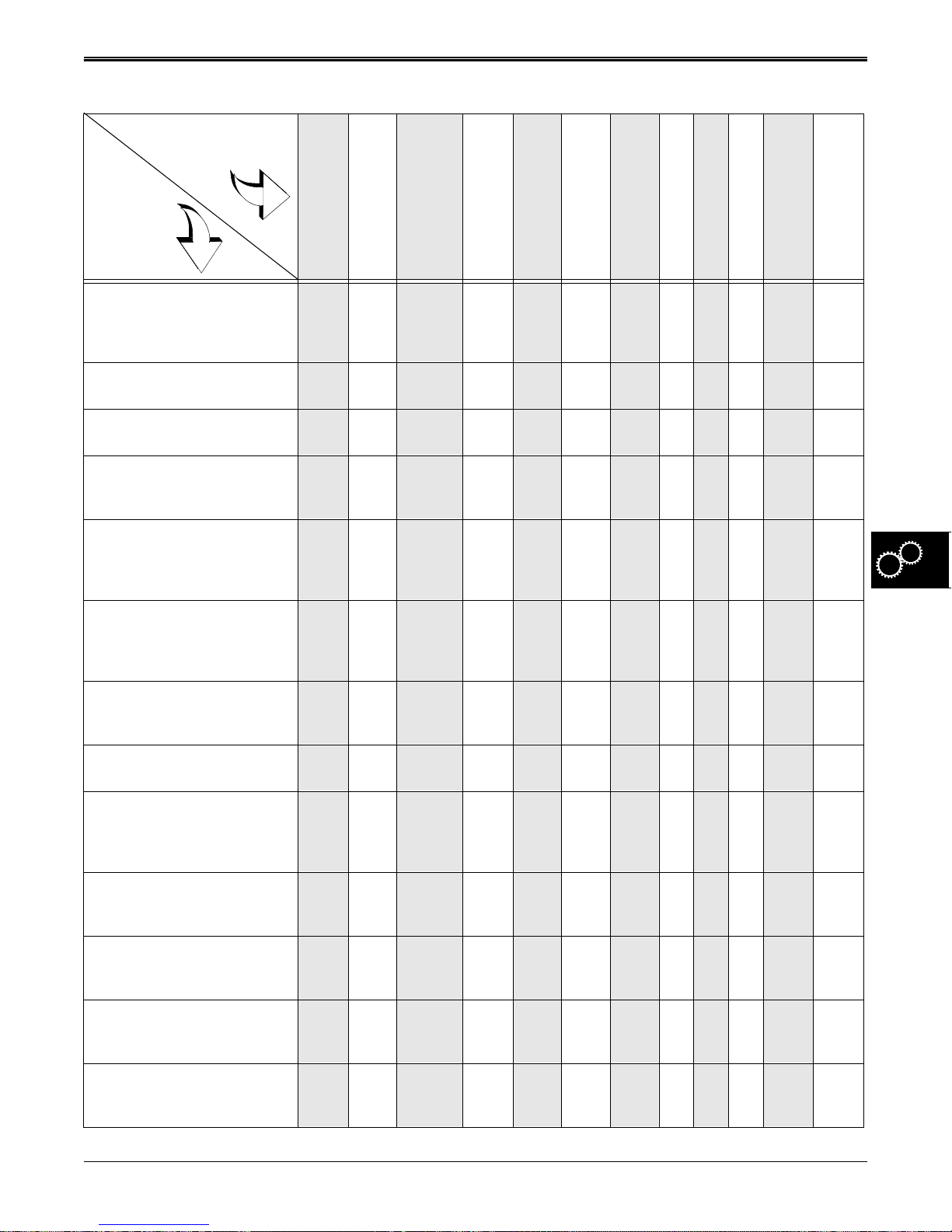
TROUBLESHOOTING GEAR POWER TRAIN
TROUBLESHOOTING
Problem or
Symptom
Check or
Solution
Belt jumping off or
slapping
Lack of drive in one
or both directions
Loses power under
load, belt slips, or
erratic drive
Jerky or aggressive
engagement
Cannot get all
forward gears
Cannot get reverse
gear
Jumps out of gear
or must hold into
Shifts hard
Noisy operation
Leaking grease
Brakes will not
stop tractor
Park brake will not
hold
Belt sheaves, idlers, &
guides loose, out of
adjustment, worn, or
damaged
●● ●● ●
Belt worn, frayed, glazed,
or stretched—replace belt
Clutch/brake pedal
linkage out of adjustment
Clutch/brake components
worn, bent, or broken—
replace and adjust
Shift lever and linkage
bent, worn, out of
adjustment, or broken—
replace or adjust properly
Input sheave, input shaft,
and axle keys or keyways
worn or damaged—
replace
Internal transaxle
components worn,
stripped, or broken
Transaxle case halves
worn or broken—replace
Incorrect type or volume
of lubricant used—replace
with correct type and
volume
●● ●● ●
●● ●● ●● ●●
●● ●●●●●●● ●●
●●●●
● ●● ● ●●
●● ●●●●●●● ●●
●● ●●●● ● ●●
●● ●●●●●●●●
Intermediate shifter/brake
shaft or axle seals worn or
damaged—replace seals
Transaxle cap screws
loose or case holes
stripped
Poor application of
sealant on transaxle case
halves
Incorrect type sealant—
replace with proper
sealant
2/12/97 5 - 5
www.servicemanualall.com
● ● ●●●●●●
● ● ●●●●●●
●
●
Page 57
GEAR POWER TRAIN COMPONENT LOCATION
COMPONENT LOCATION
1. Flange bearing 45. Spacer
2. Shim 46. Drive chain drive sprocket (9 teeth)
3. Spur gear (14 teeth) 47. Drive shaft bevel gear (42 teeth)
4. Shift collar 48. Shim
5. Shift key (4 used) 49. Drive shaft
6. Shifter Fork 50. Drive shaft 1st gear (12 teeth)
7. Intermediate shifter/brake shaft 51. Drive shaft 2nd gear (15 teeth)
8. Woodruff key 52. Drive shaft 3rd gear (20 teeth)
9. Upper case housing 53. Drive shaft 4th gear (23 teeth)
10. O-ring seal (2 used) 54. Drive shaft 5th gear (28 teeth)
11. Screw (2 used) 55. Spacer
12. Detent ball (2 used) 56. Washer
13. Detent spring (2 used) 57. Flange bearing
14. Set screw (2 used) Flush Only 58. Square-cut rubber ring
15. Shifter shaft rubber boot 59. Left axle shaft
16. Screw (14 used) 60. Washer (0.758x1.25x0.031 in.)
17. Retaining ring 61. Washer (0.758x1.25x0.031 in.)
18. Drive chain large sprocket /reverse gear (18 teeth) 62. Differential bevel gear (15 teeth)
19. Spacer 63. Retaining ring
20. Intermediate shaft 1st gear (37 teeth) 64. Differential ring gear (32 teeth
21. Intermediate shaft 2nd gear (35 teeth) 65. Differential bevel gear (15 teeth)
22. Intermediate shaft 3rd gear (30 teeth) 66. Retaining ring
23. Intermediate shaft 4th gear (27 teeth) 67. Differential bevel gear (15 teeth)
24. Intermediate shaft 5th gear (22 teeth) 68. Shim
25. Spacer w/internal keys 69. Shim
26. Washer 70. Right axle shaft
27. Flange bearing 71. Square-cut rubber ring
28. Square-cut rubber seal (open lip to inside) 72. Differential cross shaft
29. Drive chain (24 pitches) 73. Differential bevel gear (15 teeth)
30. Retaining ring 74. Lower case housing
31. Shim 75. Thin friction puck
32. Needle bearing (2 used) 76. Brake disc
33. Washer (2 used) 77. Thick friction puck
34. Input shaft 78. Friction puck striker plate
35. Bevel pinion gear (14 teeth) 79. Brake housing
36. Woodruff key 80. Brake lever
37. Retaining ring 81. Washer
38. Washer 82. Lever stop bracket
39. Spacer 83. Cap screw (5/16x1.44.)
40. Washer 84. Lock nut (5/16)
41. Idler gear (12 & 35 teeth) 85. Lever Stop bushing
42. Shim 86. Actuator dowel pin (2 used)
43. Idler shaft 87. Washer
44. Flange bearing 88. Cap screw (5/16x2.25)
5 - 6 2/12/97
www.servicemanualall.com
Page 58
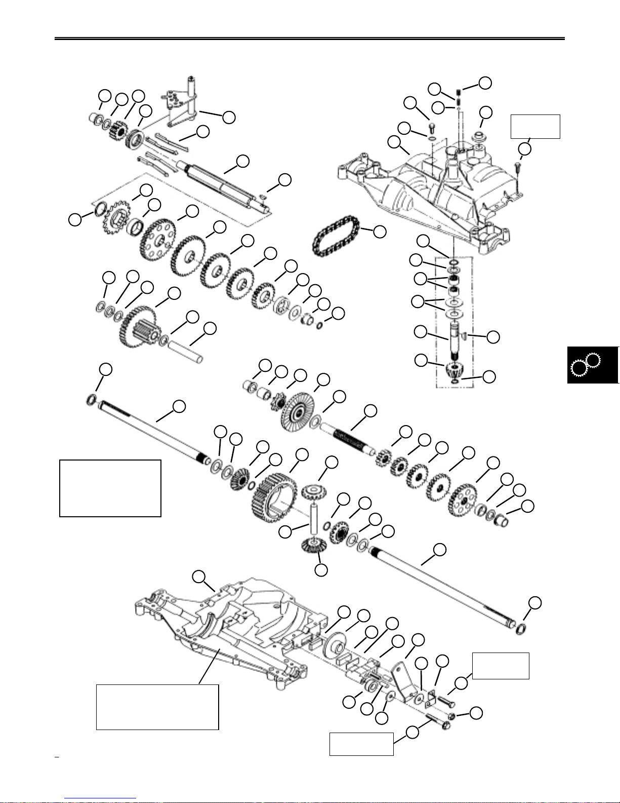
COMPONENT LOCATION GEAR POWER TRAIN
TRANSAXLE COMPONENT LOCATION
14
Flush Only
15
10 N•m
(88 lb-in.)
16
36
17
1
38
3
2
39
18
4
40
19
20
41
6
5
7
8
21
22
23
24
10 N•m (88 lb-in.)
10
9
29
25
26
27
42
43
28
13
11
12
30
31
32
33
34
58
Shims (42 and 48)
are critical when any
gears or case halves
are being replaced.
59
74
60
61
62
44
63
45
72
46
64
73
47
65
48
66
75
76
67
49
77
68
69
78
79
50
80
35
51
70
52
37
53
54
55
56
57
71
Use Form-In-Place
Gasket Silicone Sealant
to seal housing halves.
2/12/97 5 - 7
www.servicemanualall.com
85
86
22 N•m
(190 lb-in.)
87
88
81
82
22 N•m
(190 lb-in.)
83
84
Page 59
GEAR POWER TRAIN COMPONENT LOCATION
TRACTION DRIVE SYSTEM COMPONENT LOCATION
1. Frame weldment—idler adjustment
2. Carriage bolt (M8x45)
3. Clutch bellcrank bracket
4. Bushing
5. Cap screw
6. Clutch assist spring assembly
7. Carriage bolt (M8x45)
8. Clutch cross shaft
9. Park lever
10. Idler
11. Carriage bolt (M8x50)
12. Clutch spring
13. Washer (2 used)
14. Belt guide
15. Flange nut (M8)
16. Crankshaft drive sheave
17. Foot pad
18. Cap screw (M8x35)
19. Bellcrank
20. Drive belt
21. Clutch/brake pedal
22. Flange lock nut (M8)
23. Cotter pin
24. Washer
25. Clutch sheave
26. Park locking rod tension spring
27. Flange nut (M6)
28. Park locking rod
29. Flange nut (M8)
30. Rolled pin (M4x20)
31. Safety wire
32. Washer
33. Brake rod compression spring
34. Brake compression spring strap
35. Flange nut (M8)
36. Adjustable idler
37. Belt guide
38. Flange nut (M8)
39. Cotter pin
40. Belt guide
41. Flange nut (M8)
42. Brake rod
43. Cotter pin
44. Washer
45. Brake lever
46. Brake rod return spring
47. Flange nut (M6)
48. Belt guide
49. Transaxle drive sheave
50. Snap ring
51. Lock nut (M8)
52. Cap screw (M8x30)
53. Special patch lock cap screw
54. Lock washer (1/4 in.)
55. Washer
56. Cap screw (M8x30)
57. Shift knob
58. Shift lever
59. Right shift lever mounting bracket
60. Lock nut (M8)
61. Special square hole washer
62. Shift arm
63. Lock nut (M8)
64. Universal shift link
65. Lock nut (M8)
66. Left shift lever mounting bracket
5 - 8 2/12/97
www.servicemanualall.com
Page 60
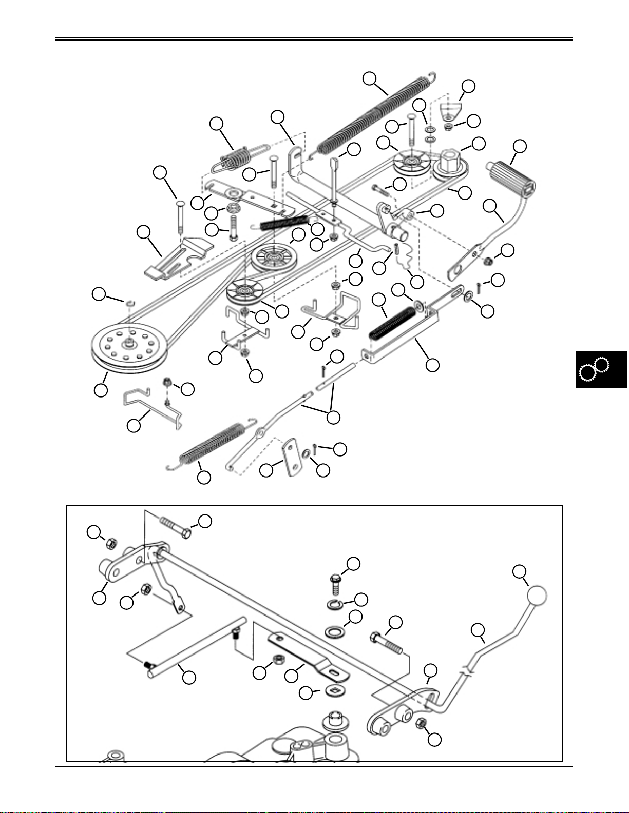
COMPONENT LOCATION GEAR POWER TRAIN
TRACTION DRIVE SYSTEM COMPONENT LOCATION
50
49
12
13
6
2
3
4
1
5
40
47
8
9
7
26
25
27
28
29
36
35
37
38
39
41
30
33
10
11
18
32
31
34
19
20
14
15
16
17
21
22
23
24
48
46
SHIFT LINKAGE SYSTEM COMPONENT LOCATION
52
51
66
65
64
63
62
61
42
43
4445
53
55
54
56
58
59
57
2/12/97 5 - 9
www.servicemanualall.com
60
Page 61
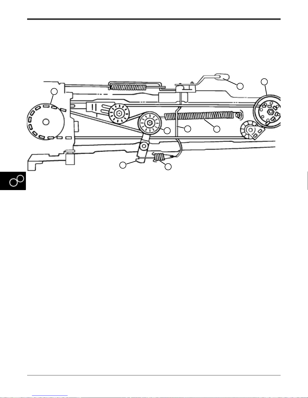
GEAR POWER TRAIN THEORY OF OPERATION
THEORY OF OPERATION
TRACTION DRIVE SYSTEM
OPERATION
H
E
F
A. Clutch Pedal E. Tensioning Sheave
B. Engine Drive Sheave F. Bellcrank Assembly
C. Tensioning Spring G. Actuating Spring Assembly
D. Clutch Shaft H. Transaxle Drive Sheave
G
D
C
A
B
Function:
The belt traction drive transfers power from the engine
to the 5-speed transaxle. The clutch pedal controls the
belt traction drive, and allows the transaxle to be
shifted through it’s five speed range.
With engine running and clutch engaged (clutch pedal
(A) released), the engine drive sheave (B) pulls the
drive belt and transmits power to the transaxle drive
sheave (H). As clutch/brake pedal (A) is depressed by
the operator, clutch shaft (D) pulls the clutch actuating
spring assembly (G) forward. Initial movement of the
pedal compresses the spring in the actuating spring
assembly (G) and, once compressed, pivots the
bellcrank assembly (F). As the bellcrank assembly
pivots, the tensioning sheave (E) moves rearward,
releasing drive belt tension. This allows the engine
drive sheave to rotate without transferring any power
through the slackened drive belt.
As the bellcrank pivots rearward, belt tensioning spring
(C) is stretched, building additional tension in the
spring. As the operator begins to ease-up on the
clutch/brake pedal (A), tensioning spring (C) pulls the
bellcrank tensioning sheave (E) into the drive belt,
causing the belt to tighten and seat in the grooves of
the transaxle drive sheave (H) and the engine drive
sheave (B). This interaction of components results in
turning the transaxle drive sheave rapidly in a
clockwise direction, transferring power from the engine
to the 5-speed transaxle.
5 - 10 2/12/97
www.servicemanualall.com
Page 62
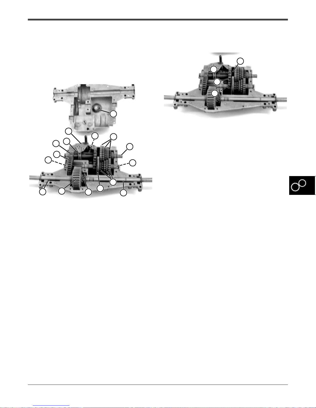
THEORY OF OPERATION GEAR POWER TRAIN
TRANSAXLE OPERATION
Function:
The transaxle transmits power from the engine to the
drive axles and rear wheels, and provides gear
selection of five forward speeds, one reverse, and
neutral.
A
H
O
G
N
F
K
A. Input Pinion Gear
B. Intermediate Gears
C. Drive Shaft
D. Forward Drive Gears
E. Cross Shaft Bevel Gears
F. Idler Shaft
G. Spur Gear
H. Shift Fork
M
Forward Gears:
With engine running and clutch engaged, the transaxle
drive sheave, input shaft, and input pinion gear (A), are
driven by the engine and traction drive belt.
The input pinion gear (A), which is splined to the input
shaft and retained by a snap ring, drives the beveled
drive gear (L). The beveled drive gear turns the drive
shaft (C), and the five forward drive gears (D).
A forward gear is selected when the operator moves
the shift lever. The shift linkage moves the shift fork
(H), shift collar (O), and shift keys (I) into one of the five
intermediate gears (B). The selected gear is keyed to
the intermediate shaft (J). Power is transferred by the
intermediate gear (B) on the right side of the
intermediate shaft, to the splined spur gear (G) on the
left side of the shaft.
The spur gear (G) drives the idler gear (N), splined to
the idler shaft (F), which transfers power into the
differential ring gear (M). Power is transferred by the
I
E
I. Shift Keys
J. Intermediate Shaft
K. Drive Axles
L. Beveled Drive Gear
M. Differential Ring Gear
N. Idler Gear
O. Shift Collar
B
J
D
L
K
C
cross shaft and bevel gears (E) to both drive axles (K)
out to the wheels and tires. The keyed drive wheels are
retained by an E-Ring.
R
S
T
U
Reverse Gears:
With engine running and clutch engaged, the transaxle
drive sheave, input shaft, and input pinion gear (A), are
driven by the engine and traction drive belt.
Power is transferred to the bevel drive gear (L), and
drive shaft (C), which drives the small drive chain
sprocket (U), the drive chain (T), and the large drive
chain sprocket (S) on the intermediate shaft (J).
When the operator shifts into reverse, the shift fork (H),
shift collar (O), and shift keys (I) become keyed to the
large drive chain sprocket (S). The large drive chain
sprocket (S) turns the intermediate shaft (J) and the
spur gear (G). The idler shaft (F) and idler gear (N) are
driven by the spur gear in reverse, which turn the
differential, drive axles, and drive wheels in reverse.
Neutral:
When the operator moves the shift lever into neutral
position, the shifter fork (H) places the shift keys (I)
under the free-floating spacer (R), allowing no power to
be transmitted into the intermediate shaft (D), which
also allows neutral to be maintained with clutch pedal
released and engine running.
2/12/97 5 - 11
www.servicemanualall.com
Page 63
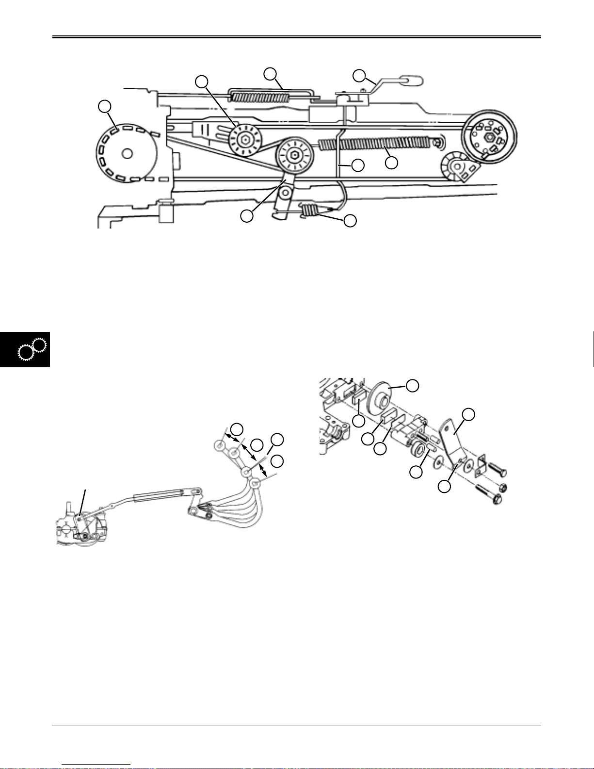
GEAR POWER TRAIN THEORY OF OPERATION
BRAKE SYSTEM OPERATION
E
F
G
A
B
D
A. Clutch/Brake Pedal E. Adjustable Idler Assembly
B. Clutch Cross Shaft and Bellcrank F. Transaxle Drive (Input) Sheave
C. Clutch Actuating Spring Assembly G. Brake Rod Assembly
D. Clutch Bellcrank and Tensioning Idler Assembly H. Clutch Tensioning Spring
Function:
The brake system allows the operator to slow down,
stop, or lock the tractor into park position.
There is a small segment of pedal travel (P) that briefly
allows the tractor to free-wheel so the operator can
shift-on-the-go before the brake starts to engage. This
segment can be adjusted to allow more overlap
C
H
between clutch and brake functions, if desired.
Theory of Operation:
NOTE: Clutch/brake pedal has approximately 127 mm
(5 in.) of travel, and operates as follows:
M
L
K
Transaxle
Brake Assembly
N
P
O
Q
R
S
J
I
The first movement of the clutch/brake pedal (N) is
used for taking-up freeplay in the linkage and the
beginning of compressing the clutch actuating spring
assembly (C).
The next segment of pedal travel (O) is fully
compressing the clutch actuating spring assembly (C),
and pulling the clutch bellcrank and idler assembly (D)
fully rearward, overcoming the belt tensioning spring
(H) and fully disengaging the traction drive system.
As the pedal is released, belt tensioning spring (H)
pulls the clutch bellcrank and tensioning idler assembly
(D) forward into the belt, tensioning the belt and fully
engaging the traction drive system.
5 - 12 2/12/97
www.servicemanualall.com
The last segment of travel (Q) fully engages the brake
system. The brake lever (S), with the bottom cam
surface contour (I), pushes the two dowel pins (J)
against the striker plate (K). The striker plate forces the
thicker, outer friction puck (L) against the brake disc
(H). The two friction pucks (L and M) become
compressed against both sides of the brake disc (R).
The brake disc is keyed to the end of the intermediate
shifter/brake shaft (not shown). When the compression
force of the friction pucks is great enough to stop the
brake disc rotation, the transaxle and wheels stop
turning. This works in conjunction with the clutching
system.
With the clutch/brake pedal (A) fully depressed and the
traction drive system disengaged (fully clutched), the
park brake lever assembly (not shown) can be
engaged, locking the clutch/brake pedal linkage and
the brake disc in the park position.
Page 64
DIAGNOSIS GEAR POWER TRAIN
DIAGNOSIS
Test Conditions:
• Mower on level surface
• Mower deck removed
• Engine OFF
Test/Check Point Normal If Not Normal
1. Inspect traction drive belt. Belt in good condition, not glazed, split,
2. Inspect engine and transaxle
sheaves, idlers and idler
bearings, and belt guides.
3. Test drive mower up 17° slope
in first, second, third and
reverse gears.
4. Shift linkage adjustment. Linkage shifts smoothly, obtains all
5. Inspect exterior of transaxle
housing.
• Front wheels blocked
• Rear wheels raised off ground with axle housings on jack stands.
• Park brake ON
unraveled, or stretched.
Minimum width 11 mm (0.43 in.).
Sheaves, idlers and guides in good
condition.
Guides installed, properly adjusted and
tight.
Mower pulls up slope with no clutch
slippage (traction drive belt adjusted
properly).
gears & neutral (See shift linkage
adjustment section for test)
No cracks, leaks, or loose hardware. Repair or replace as necessary. If
Replace traction drive belt
See Repair section for removal/
installation instructions
Replace any loose, worn, or
damaged components.
(See Repair section for removal/
installation instructions)
Adjust traction drive belt rear idler
(See clutch actuating spring
adjustment)
Adjust linkage. (See shift linkage
adjustment section for procedure)
case seal is leaking, reseal case
6. Perform brake test (See tests
and adjustments)
7. Inspect brake pads & disk Pads and disks not worn beyond
8. Inspect brake linkage Brake spring adjustment is 7.5-8 mm
9. Inspect rear tires Tire pressures are equal Adjust air pressure.
10. Inspect rear wheels Wheels not bent or out of round. Replace wheels.
11. Remove rear wheels and
inspect axles.
Test Conditions:
• Mower on level surface
• Front wheels blocked
• Park brake OFF
1. Depress clutch pedal and shift
into all 5 speeds and reverse
Mower holds on 17° slope, and stops in
0.9-1.5 M (3-5 ft) or less.
specifications. Disc not rubbing on
transaxle case.
(0.30-0.32 in.)(See tests & adjustments
section)
Tire outside diameters are equal Match tires for same size.
Keys, keyways and E-rings in good
shape and seated correctly.
• Rear wheels raised off ground with axle housings on jack stands.
• Operator on seat, engine running at operating temperature.
Rear wheels remain still with no axle
rotation (Clutch pedal down)
Go to step 7 and 8
Replace pad & disk as needed. If
disk is rubbing case, rebuild
transaxle
Adjust brakes (See tests &
adjustments section)
Repair or replace as needed.
Adjust clutch actuating spring.
2. Shift transaxle through gears,
using clutch to shift
2/12/97 5 - 13
www.servicemanualall.com
Shifts smoothly, and obtains all forward
and reverse gears (both rear wheels are
being driven)
Adjust shift linkage
If still no drive, check transaxle
drive sheave shaft key, or remove
transaxle for internal inspection.
Page 65
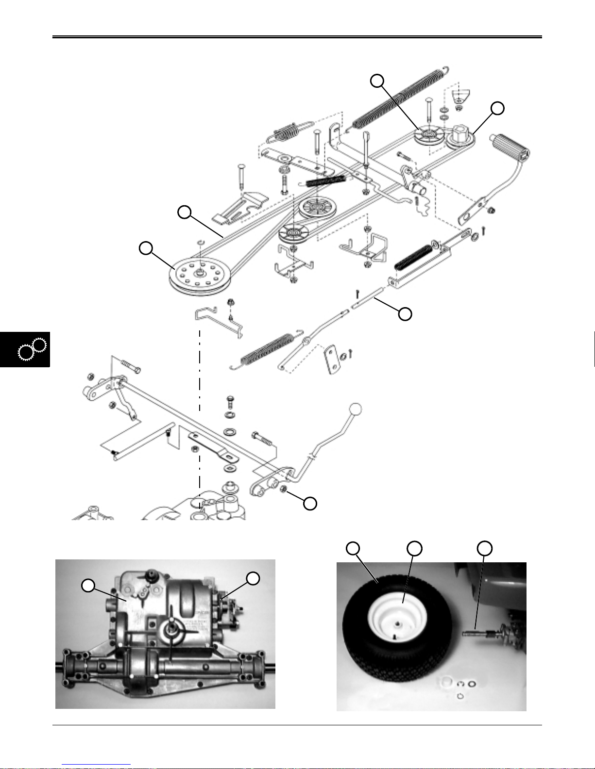
GEAR POWER TRAIN
1
2
2
2
8
4
9
5
7
10
11
5 - 14 2/12/97
www.servicemanualall.com
Page 66
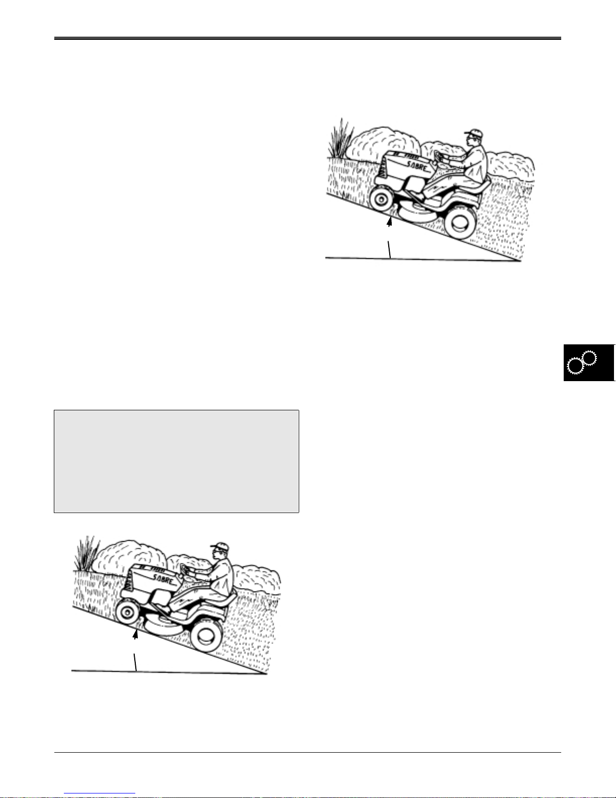
TESTS AND ADJUSTMENTS GEAR POWER TRAIN
TESTS AND ADJUSTMENTS
CLUTCH/BRAKE LINKAGE
&TRACTION DRIVE ADJUSTMENT
Reason:
To ensure clutch/brake pedal linkage and traction drive
system maintains traction in all three lower gears up a
17° slope. Also, to ensure it disengages traction drive
belt, engages brake to slow down or stop tractor within
a specified distance, and holds tractor stationary in
PARK position on a 17° slope or less.
Procedure:
NOTE: This is a four part test and adjustment
procedure:
1. Test drive on 17° slope,
2. Brake spring adjustment,
3. Clutch spring adjustment,
4. Repeat test drive on 17° slope.
TRACTION BELT DRIVE TEST
?
DO NOT engage clutch/brake pedal too
aggressively or tractor may tip over backwards.
It is recommended that you install the mower
deck before performing the test drive on a 17°
slope.
CAUTION
2. Look for a steady pull in all three lower gears up the
slope.
3. If traction test fails in any or all of the three lower
gears, the belt tension must be adjusted.
17°
BRAKE TEST
1. Drive or push tractor onto a 17° slope and lock
clutch/brake pedal in PARK position.
2. Park brake must hold tractor stationary on slope
and tractor must not roll downward once park
brake is set.
3. Drive tractor on dry pavement in a safe, open, and
level area at fast idle in high gear. Apply a “panic
stop” force (no more than 50 pounds of force) to
brake pedal—tractor must stop within 0.9—1.5 M
(3—5 ft) and both wheels should lock-up, leaving
skid marks on pavement.
4. Repeat Steps 4—6 for reverse.
5. If any test fails, the clutch and brake linkages must
be adjusted or components replaced.
IMPORTANT: Anytime the brake or clutch spring
need to be adjusted, both must be examined to
ensure desired results will be obtained.
17°
1. T est drive tractor to see if traction drive system pulls
tractor up a 17° slope in all three lower gears.
2/12/97 5 - 15
www.servicemanualall.com
NOTE: These adjustment procedures can be
performed with tractor on the floor; however,
you may want to safely raise the tractor for
easier access. If you do, remove the battery to
avoid spilling any electrolyte solution.
Page 67
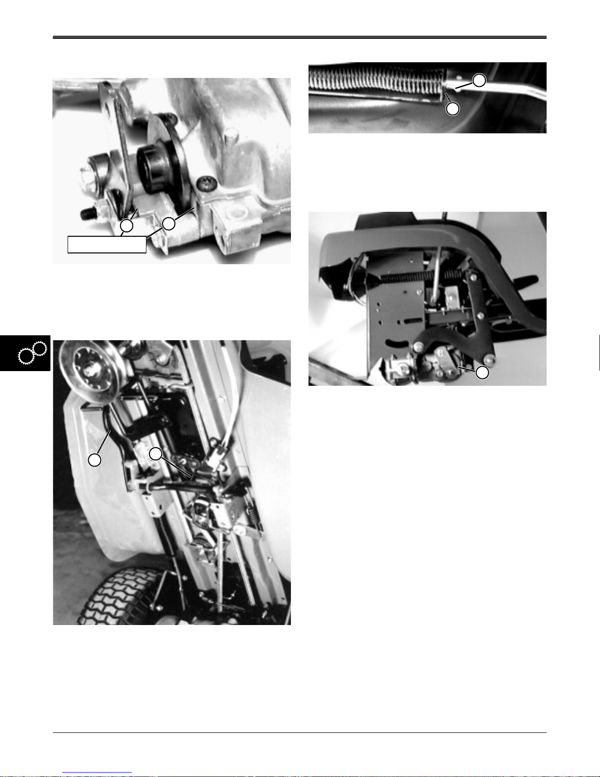
GEAR POWER TRAIN TESTS AND ADJUSTMENTS
BRAKE SPRING ADJUSTMENT—
D
C
4. Measure distance between end of compression
spring bracket (C) and front edge of brake rod stop
tabs (D).
• If distance is less than 2 mm (0.08 in.)—
2
1
Contact Points
1. First check for brake disc contacting the case (1)
and/or brake lever contacting its mounting bracket
(2), top or bottom. If so, replace friction pucks and
disc before making any adjustments.
A
B
E
5. Tighten lock nut (E) until distance between end of
compression spring bracket (C) and front edge of
brake rod stop tabs (D) is 7.5—8 mm (0.30—0.32
in.)
6. Once above measurement is obtained, cycle clutch/
brake pedal.
7. Remeasure distance, it should be the same. This
brake setting should hold the tractor stationary on a
17° slope.
If distance is greater than 8 mm (0.32 in.)—
8. With park brake set, gradually loosen lock nut (E)
until distance of 7.5—8 mm (0.30—0.32 in.) is
obtained.
9. Cycle park brake and measure distance again (see
Step 7).
10. If tractor fails either brake test, inspect brake
assembly components, replace as necessary, and
repeat all adjustment procedures and drive tests.
2. Remove the mower deck.
3. Depress clutch/brake pedal (A) and lock park brake
lever (B) into PARK position from operator’s
station.
5 - 16 2/12/97
www.servicemanualall.com
CLUTCH ACTUATING SPRING ADJUSTMENT
IMPORTANT: Anytime the brake or clutch spring
need to be adjusted, both must be examined to
ensure desired results will be obtained.
Page 68
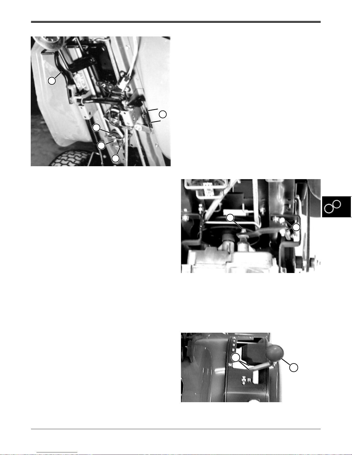
TESTS AND ADJUSTMENTS GEAR POWER TRAIN
• shortening the clutch spring causes decreased
drive traction and aggressiveness.
SHIFT LINKAGE ADJUSTMENT
A
B
C
E
D
1. Unlock park brake and release pedal (A).
2. Measure clutch actuating spring length (B).
Measurement should be 42—45 mm (1.65—
1.77in.). Clutch actuating spring length is adjusted
by sliding rear idler sheave (C) on it’s slotted
mounting bracket, as follows:
3. Depress brake/clutch pedal (A) and lock park
brake.
4. Remove belt guide (D) to access idler sheave
mounting nut (E). Loosen mounting nut and adjust
idler as follows:
• If spring length is less than 42 mm (1.65 in.), slide
idler rearward.
• If spring length is greater than 45 mm (1.77 in.),
slide idler forward.
5. Tighten idler nut (E).
6. Cycle pedal in and out two or three times
measuring clutch spring length each time.
Measurement must fall within 42—45 mm
(1.65—1.77 in.) each time. If not, continue to
adjust rear idler slightly until it does.
7. Install belt guide (D). This clutch spring setting
should provide proper belt tension to pull tractor up
a 17° slope in all three lower gears.
8. Install battery, if removed.
Reason:
To ensure shift lever obtains all shift positions and that
neutral position does not allow transaxle to rotate.
Conditions:
• Remove deck
• Safely raise rear wheels 51 mm (2 in.) off ground
and block front wheels (front and rear).
• Shift lever in neutral.
• Park brake off.
Procedure:
A
B
1. Check that shift linkage hardware (A and B) is in
good condition and tight.
2. Start and run engine at fast idle.
3. Check that transaxle does not rotate while shift
lever (D) is in neutral position (C), and clutch/brake
pedal released.
REPEAT TEST DRIVE
1. Repeat test drive in at beginning of this section.
2. If tractor fails either brake test, inspect brake
assembly components, replace as necessary, and
repeat all adjustment procedures and drive tests.
3. If belt is not excessively worn, make small
adjustments to idler sheave to obtain proper
response in traction drive system as follows:
• lengthening the clutch spring causes increased
drive traction and aggressiveness
2/12/97 5 - 17
www.servicemanualall.com
C
D
Page 69
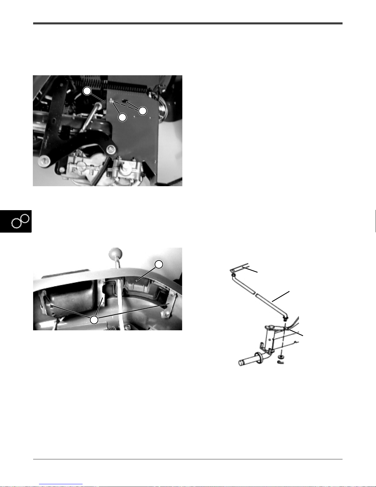
GEAR POWER TRAIN REPAIR
4. If transaxle rotates, move shift lever (D) slightly until
transaxle shift lever clicks firmly into it’s neutral
detent. (This may occur while shift lever (D) is in
the reverse or first gear range of shift gate).
5. Stop engine.
F
G
E
6. Raise seat and loosen left side lock nut (E) holding
shift linkage bracket to frame. (Left wheel removed
for clarity purposes only).
Slide shift linkage bracket (F) forward or rearward
in slots (G) until shift lever is centered in neutral
shift gate. Tighten lock nut (E).
Results:
• Test drive tractor to ensure all forward and reverse
gears are obtained and that tractor does not move
when shifter is in neutral position.
• If adjustments are not satisfactory, repeat
procedure until proper results are obtained.
• If adjustments are still not satisfactory, internal
transaxle repair is needed.
REPAIR
TRACTION DRIVE BELT REMOVAL
NOTE: If drive belt is in good condition, it does not
need to be removed when removing transaxle.
Engage park brake and remove belt from
transaxle drive sheave.
1. Park mower on level surface.
2. Remove mower deck.
3. Safely raise and block tractor to gain easy access
to underside of frame.
NOTE: If mower is to be raised at an angle, remove
battery from frame before jacking.
H
I
7. If left side bracket adjustment (Step 6) does not
allow enough shift lever movement to center shift
lever in neutral gate, loosen three mounting
brackets (I) holding shift quadrant (H) to fender.
8. Adjust quadrant forward or rearward until shift lever
is centered in the neutral gate.
9. Tighten mounting brackets (I). Restart engine and
move shift lever through all gears (using clutch to
shift). Re-check for axle rotation in neutral (steps 2
through 4 this section).
10. Lower tractor to surface and remove blocks.
Steering Arm
Steering Link
Spindle Shaft
4. Remove cotter key and washer holding steering link
to right front spindle shaft.
5. Rotate steering link to align tabs on link with slots in
steering arm. Remove link from arm.
5 - 18 2/12/97
www.servicemanualall.com
Page 70
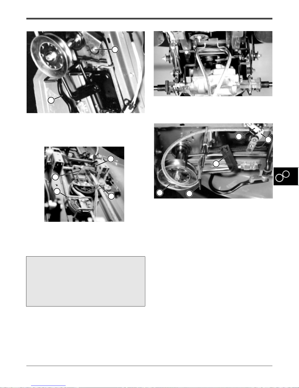
REPAIR GEAR POWER TRAIN
B
A
12. Remove belt from transaxle drive sheave, and pull
through transaxle belt guide.
6. Depress and lock brake pedal (A) with park brake
lever.
7. Remove front idler belt guide and sheave (B).
K
J
F
E
D
8. Remove clutch bellcrank belt guide (C).
9. Remove adjustable idler belt guide (D).
10. Remove park lever (E).
?
Mower drive lever return spring is under tension
and located inside frame. Use pliers or spring
puller tool to remove spring. Protect your eyes
and face from the possibility of spring being
released at high speed.
11. Remove mower drive lever return spring (F)
CAUTION
C
I
G
13. Pull belt from around engine drive sheave (G), and
past front belt guide (H). Pull belt under belt guide
and around steering arm (I).
14. Rotate mower drive lever to allow belt to pass
between lever (J) and switch (K).
15. Remove belt from clutch bellcrank and idler
sheave, and remove belt from mower.
H
TRACTION DRIVE BELT
INSPECTION
1. Examine belt to determine if it is worn, stretched,
cracked, frayed, or damaged beyond the point of
continued use.
2. Measure and compare removed belt to the
following:
New Belt Dimensions:
Length. . . . . . . . . . . . . . . 2660±8 mm (104.7±0.3 in.)
Minimum length . . . . . . . . . . . 2631 mm (103.6 in.)
Maximum length. . . . . . . . . . . 2710 mm (106.7 in.)
Top width . . . . . . . . . . . . . . . . . . 12.7 mm (0.500 in.)
Minimum top width . . . . . . . . . . . 11 mm (0.43 in.)
Depth . . . . . . . . . . . . . . . . . . . . . 7.874 mm (0.31 in.)
Minimum depth. . . . . . . . . . . . . . . . 7 mm (0.28 in.)
3. Replace belt if any of above dimensions are not
found.
2/12/97 5 - 19
www.servicemanualall.com
Page 71
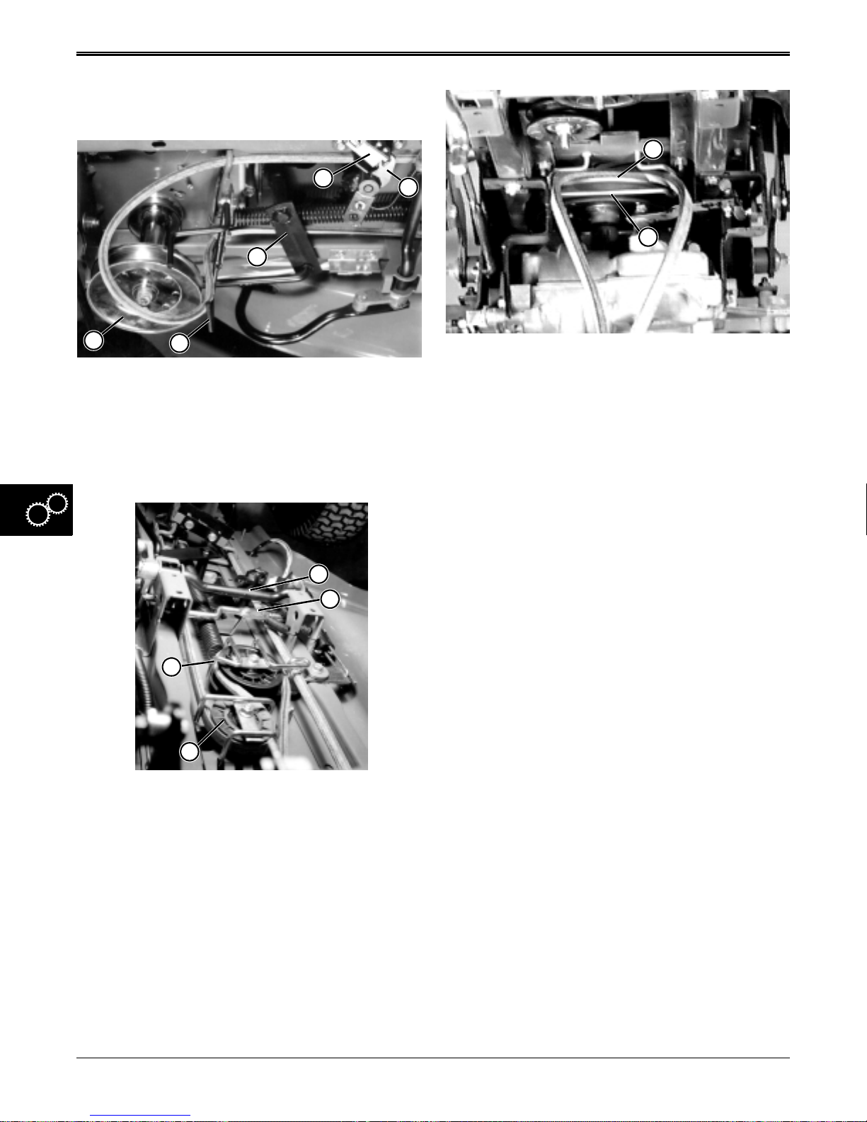
GEAR POWER TRAIN REPAIR
TRACTION DRIVE BELT
INSTALLATION
B
K
I
G
1. Install end of drive belt under belt guide (H), and
pull belt up between guide (H) and sheave (G). Pull
belt over large sheave (G) and down into small
sheave.
2. Route belt between mower drive lever (J) and
switch (K), and around steering arm (I).
H
A
B
C
J
A
5. Install drive belt through rear belt guide (A) and
over transaxle drive sheave (B).
6. Install belt guides on clutch sheave and adjustable
idler.
7. Install park brake lever and mower drive lever
return spring.
8. Release park brake and check that belt is seated in
grooves of all sheaves and idlers.
9. Perform Clutch/Brake Pedal Linkage Adjustments,
shown earlier in this section.
TRACTION DRIVE SYSTEM
REMOVAL
1. Remove mower deck.
2. Block mower wheels securely at front and rear.
3. Engage park brake.
4. Remove traction drive belt from transaxle sheave.
5. Disengage park brake.
D
3. Route drive belt over the top of clutch cross shaft
(A) and park brake locking rod (B).
4. Route through clutch sheave (C) and adjustable
idler (D) as shown
5 - 20 2/12/97
www.servicemanualall.com
Page 72
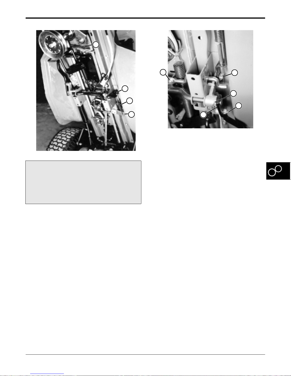
REPAIR GEAR POWER TRAIN
C
F
D
E
?
Clutch tension spring is capable of causing
extreme injury if allowed to be released quickly
from mower frame. Protect your face, eyes and
hands before releasing spring.
6. Thread one end of a three foot long piece of starter
rope under the front hook of clutch tension spring
(C). Pull rope half way through spring until ends
meet, and wrap ends around a bar several times to
make a temporary handle. Pull handle until spring
hook is free from frame, and release tension from
spring. Tension is now off traction drive system and
it may be worked on safely.
7. Remove clutch actuating spring (D) from clutch
bellcrank (E) and cross shaft (F).
CAUTION
K
I
8. Remove clutch/brake pedal by removing mounting
nut (G) and pulling pedal through frame.
9. Remove brake bracket from bellcrank by removing
cotter key and washer (H).
10. Remove bellcrank from clutch shaft by removing
safety wire (I) securing roll pin, then driving out roll
pin (J) and removing bellcrank.
11. Remove two bolts and nuts through retainer plate
holding left end of clutch shaft, and remove shaft
from frame.
12. Remove nut (K) holding parking brake lock lever to
parking brake locking rod.
13. Remove spring from frame to parking brake locking
rod and slide rod out of frame.
14. Bellcrank assembly is held to frame with one bolt
and bushing.
H
J
G
2/12/97 5 - 21
www.servicemanualall.com
Page 73
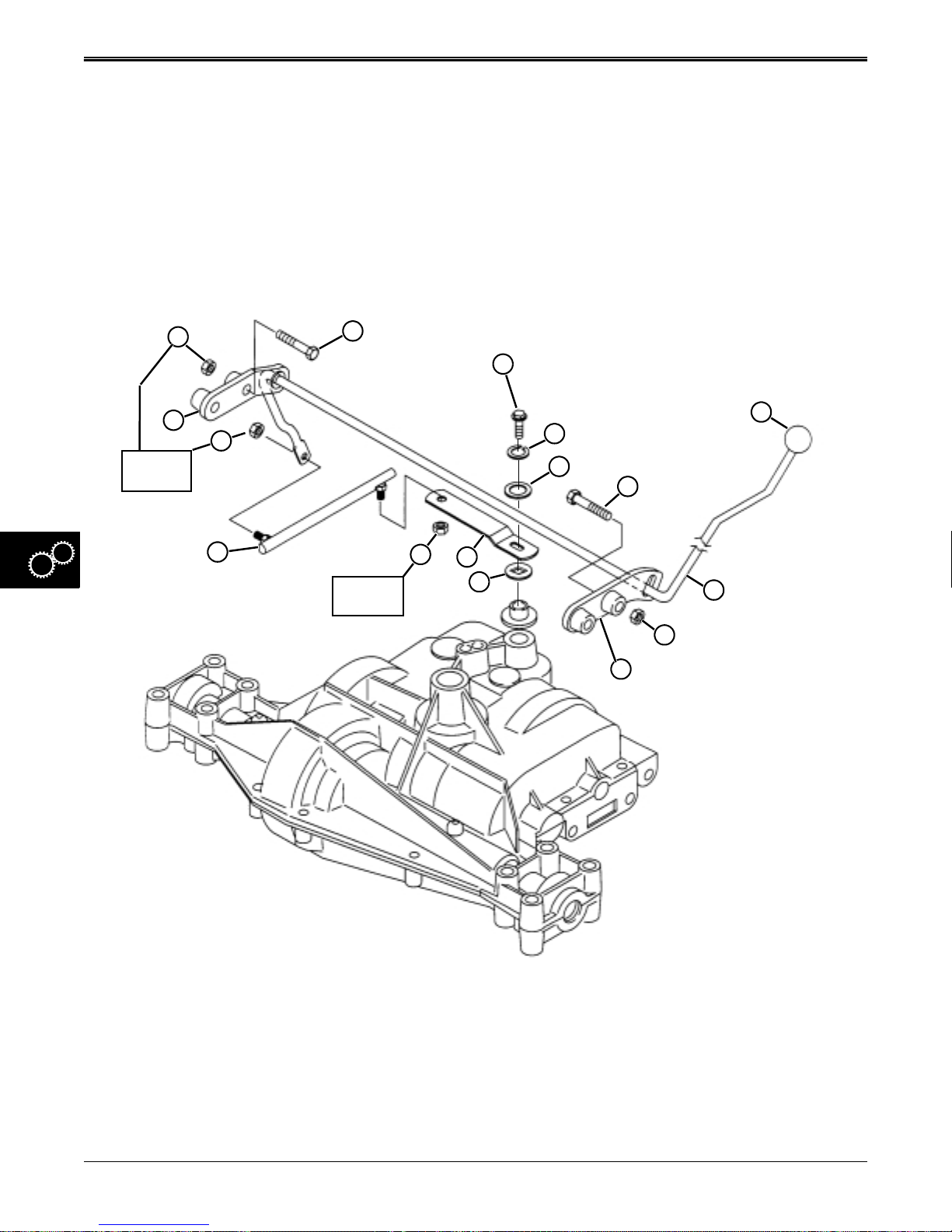
GEAR POWER TRAIN REPAIR
SHIFT LINKAGE REMOVAL &
INSTALLATION
1. Remove battery.
2. Block rear of tractor off ground. Remove left drive
wheel.
3. Remove shift knob (G).
4. Remove lock nuts (M and O) to remove shift link
(N).
5. Remove lock nuts (A and I) and cap screws (B and
F).
6. Adjust mounting brackets (J and P) so shift rod (H)
can be removed from the left side of the frame. You
will have to “snake” the shift rod from the tractor.
7. Remove cap screw (C) to remove shift lever (L) and
washers (D, E, and K).
8. Replace necessary components.
9. Install shift linkage in reverse order of removal.
10. Tighten shift lever cap screw and lock nuts to
specifications shown.
A
P
15 N•m
(11 lb-ft.)
B
C
16 N•m
(12 lb-ft.)
G
O
N
15 N•m
(11 lb-ft.)
M
L
K
D
E
F
H
I
15 N•m
(11 lb-ft.)
J
A–Lock Nut G–Shifter Knob M–Lock Nut
B–Cap Screw H–Shift Rod N–Shift Link
C–Shift Lever Cap Screw I–Lock Nut O–Lock Nut
D–Lock Washer J–Right-Hand Bracket P–Left-Hand Bracket
E–Washer K–Special Square-Hole Washer
F–Cap Screw L–Shift Lever
5 - 22 2/12/97
www.servicemanualall.com
Page 74
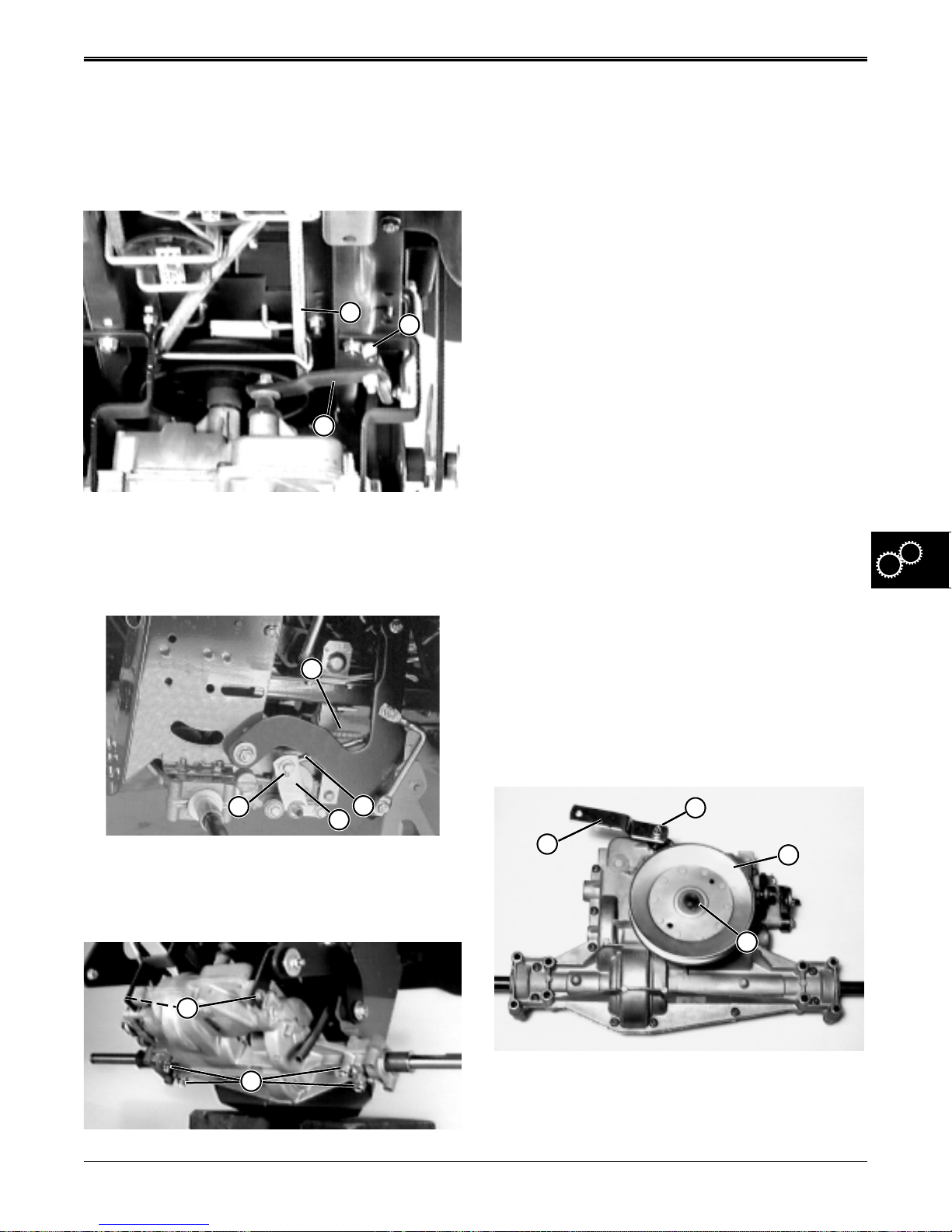
REPAIR GEAR POWER TRAIN
TRANSAXLE REMOVAL &
INSTALLATION
1. Raise mower off ground and support with
jackstands under frame and not transaxle case.
2. Remove rear wheels.
A
C
3. Disconnect shift linkage (B) from shift arm (C).
4. Remove traction drive belt (A).
Hint: Lock park brake to loosen belt. Release park
brake after removal.
7. Support transaxle with jack stands or have a helper
hold transaxle in place while you remove
hardware.
8. Remove front cap screws (F) and rear hardware
(G).
9. Carefully remove transaxle to workbench.
10. Install transaxle in reverse order of removal.
11. Tighten mounting hardware to the following
specifications:
Front Hanger capscrews
to frame. . . . . . . . . . . . . . . . . . . . 30 N•m (22 lb-ft.)
Front transaxle cap screws
B
to hangers. . . . . . . . . . . . . . . . . . 27 N•m (20 lb-ft.)
Rear axle cap screws
& nuts to frame. . . . . . . . . . . . . . 30 N•m (22 lb-ft.)
Shift linkage lock nut. . . . . . . . . . . 15 N•m (11 lb-ft.)
12. Install traction drive belt (A).
13. Install drive wheels.
14. Lower tractor to ground.
TRANSAXLE DISASSEMBLY
IMPORTANT: Maintain absolute cleanliness when
working on transaxle. The close tolerances in
this unit will not tolerate ANY dirt. Use only
clean fresh multipurpose EP grease during
assembly.
D
H
E
I
5. Disconnect clutch/brake rod return spring (D).
6. Remove cotter pin (H) and disconnect clutch/brake
rod (E) from brake lever (I).
F
G
IMPORTANT: Pay close attention to the order and
orientation of all components inside the
transaxle. Ta g and label parts, if necessary. This
will aid assembly and prevent transaxle damage
Remove Drive Sheave/Shift Arm:
D
A
B
C
1. Remove drive sheave snap ring (C).
2. Remove drive sheave (B).
3. Remove shift arm lock nut (D), lock washer, and flat
washer.
2/12/97 5 - 23
www.servicemanualall.com
Page 75
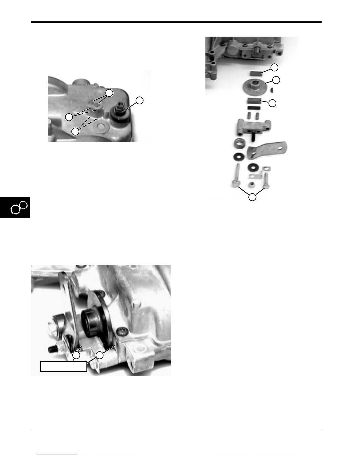
GEAR POWER TRAIN REPAIR
4. Remove shift arm (A), and square-hole flat washer
from transaxle shifter shaft
Remove Shifter Detent Assembly:
A
B
H
E
G
F
1. Remove shifter shaft rubber boot (E).
2. Remove both set screws (H) and detent springs
(G).
C
IMPORTANT: DO NOT drop or lose detent balls.
3. Use a magnet or place a shop cloth over holes and
turn transaxle upside-down to catch both detent
balls (F) in cloth.
4. Inspect detent balls and springs for wear or
damage. Replace components as necessary. Do
not install springs or detent balls until final
assembly.
Remove Brake Assembly:
D
1. Remove brake assembly by removing two outer
capscrews (D) holding caliper to transaxle.
2. It is recommended that inside (thin) brake pad (A),
and outside (thick) brake pad (C), and brake disc
(B), all be replaced when transaxle is
disassembled.
3. Inspect remaining components for wear or damage.
Replace components as necessary, but do not
install this assembly until transaxle has been
completely assembled.
Separate Transaxle Housing Case Halves:
IMPORTANT: Maintain absolute cleanliness when
working on transaxle. The close tolerances in
this unit will not tolerate ANY dirt. Use only
clean fresh multipurpose EP grease during
assembly.
12
Contact Points
IMPORTANT: Before removal, inspect brake
components for wear. Check that brake disc is
not contacting transaxle case (1), brake lever is
not contacting its mounting bracket (2) (top or
bottom). If so, all worn components must be
replaced.
5 - 24 2/12/97
www.servicemanualall.com
Page 76
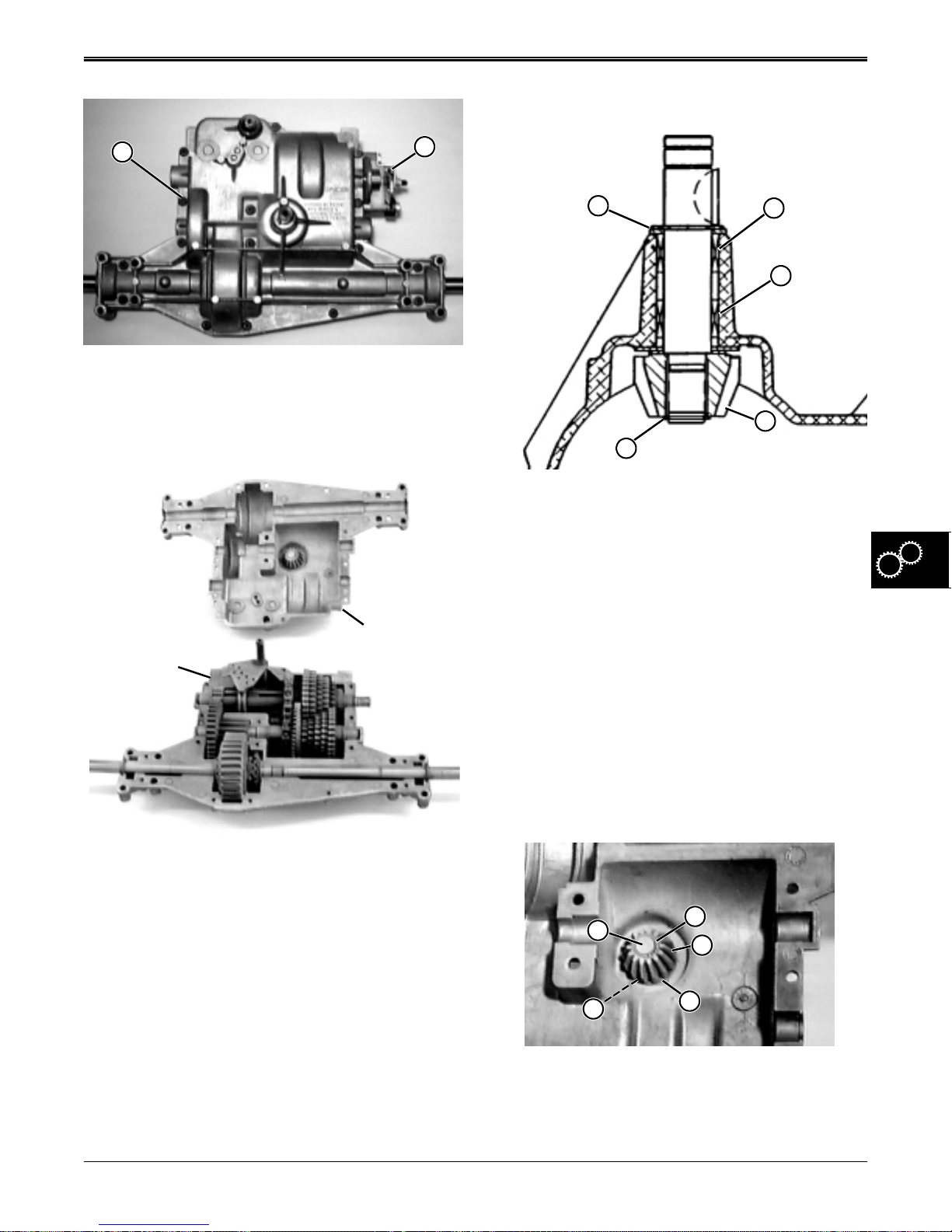
REPAIR GEAR POWER TRAIN
Input Shaft & Pinion Gear Inspection:
B
1. Remove brake assembly (A) (see previous
procedure). Remove sixteen transaxle housing
socket head screws (B).
Upper Case
Lower Case
Half
Half
A
A
E
B
C
D
1. Visually check overall condition of assembly,
including the key and keyway, and the drive
sheave hub keyway.
2. Check condition of pinion gear (D) - look for wear,
pitting, broken teeth, etc.
3. Grasp the input shaft and try to rock it left or right
inside case housing. If movement is noticeable,
replace needle bearing (B and C).
4. Use a feeler gauge to measure clearance between
pinion gear (D) and snap ring (E):
Clearance . . . . . . . . . . .0.127 mm (0.005 in.) or less.
5. If clearance is excessive, shim thickness (A) needs
to be changed or worn components must be
replaced.
2. Carefully separate transaxle housing case. Remove
upper case from lower case assembly.
3. Inspect overall condition of transaxle without
removing any components. Visually target worn or
damaged parts for replacement.
4. Remove most of the grease without removing any
components.
2/12/97 5 - 25
www.servicemanualall.com
Input Shaft/Pinion Gear Disassembly:
K
F
E
D
G
1. Remove snap ring (E), bevel pinion gear (D), small
washer (F), and large washer (G) from input shaft
(K) inside upper case half.
Page 77
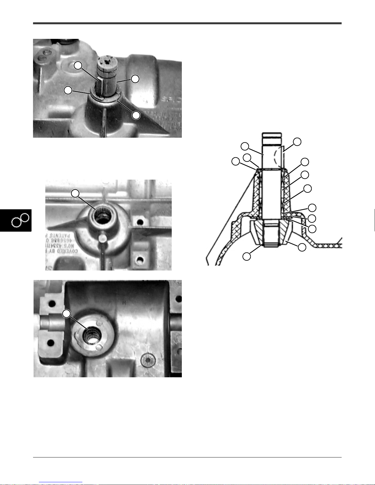
GEAR POWER TRAIN REPAIR
Bearing Inside
Diameter . . . . . 15.89–15.92 mm (0.625–0.627 in.)
6. Replace both bearings by carefully pressing them
J
K
I
from case bore without damaging bore.
7. Pack area between bearing with Multi-Purpose EP
Grease.
8. Clean and inspect bore. If scratched or deformed,
replace upper case half.
H
2. Turn upper case half so input shaft is facing up.
3. Remove woodruff key (J), E-ring (I), shim washer
(H), and input shaft (K).
J
Assemble Input Shaft/Pinion Gear Assembly:
E
D
C
L
F
A
G
B
H
I
J
K
IMPORTANT: DO NOT scratch or deform upper
case half bore when installing needle bearings.
K
IMPORTANT: DO NOT scratch or deform upper
case half bore when removing needle bearings.
4. Visually inspect condition of needle bearings, upper
bearing (J) and lower bearing (K). If needles are
discolored, spalled, scratched, missing, broken,
etc. replace bearings.
5. Measure inside diameters of each bearing:
5 - 26 2/12/97
www.servicemanualall.com
1. Pack needle bearings (A and B) with Multi-Purpose
EP Grease before installing.
2. Install lower needle bearing (B) with flat side of
bearing (with lettering) toward inside of case. Press
lower needle bearing in case bore with a maximum
recess of 0.76 mm (0.030 in.) (H) from case
surface.
3. Install upper needle bearing (A) with flat side of
bearing (with lettering) toward outside of case.
Press lower needle bearing flush with surface of
case bore. A maximum recess of 0.76 mm (0.030
in.) from case surface is also acceptable.
4. Pack cavities (G and H) with Multi-Purpose EP
grease before installing input shaft.
Page 78
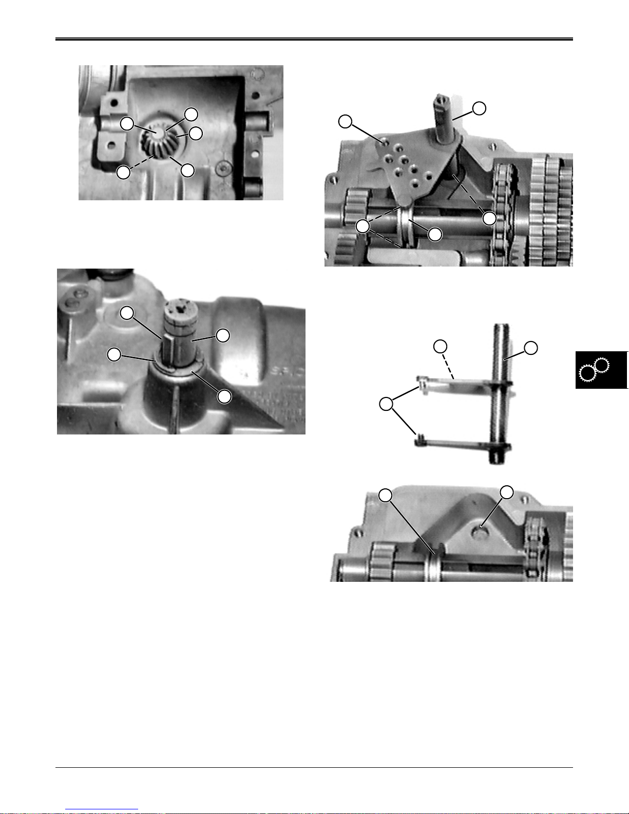
REPAIR GEAR POWER TRAIN
Shifter Disassembly:
E
J
L
K
I
5. Install input shaft (E) (with keyway on outside of
case), large washer (I), small washer (J), bevel
pinion gear (K), and snap ring (L).
F
E
D
C
B
A
E
D
C
1. Lift shifter shaft (B) from lower case half mounting
hole (C) and groove of shift collar (D).
A
E
B
6. Turn upper case half over.
7. Install a shim washer (C) (from Shim Kit) of the
proper thickness that allows enough clearance for
E-ring (D) to be installed.
8. Turn upper case half over and measure air gap
between snap ring (L) and bevel pinion gear (K):
Clearance . . . . . . . . . . .0.127 mm (0.005 in.) or less.
9. If clearance is excessive, shim thickness (C) needs
to be changed.
10. Install woodruff key (F) in shaft keyway.
D
C
2. Clean shifter assembly and inspect condition of
detent holes (A), shift pins (E), shaft (B), lower
case mounting hole (C), and shift collar (D).
3. Replace any worn or damaged parts of shifter
assembly , rubber boot, detent balls, detent springs,
or set screws.
4. If lower case mounting hole (C) is worn or
damaged, replace the case half.
5. If shift collar (D) is worn or damaged, replace it
when intermediate shaft assembly is
disassembled.
2/12/97 5 - 27
www.servicemanualall.com
Page 79
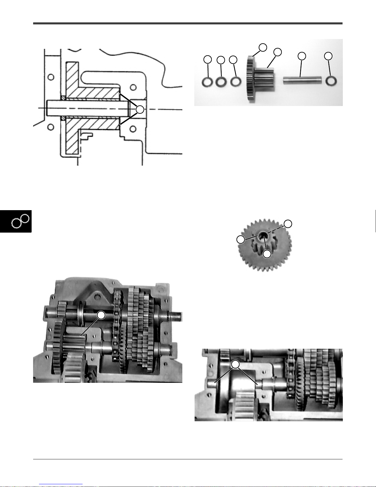
GEAR POWER TRAIN REPAIR
Idler Gear Inspection:
E
A
1. Visually check overall condition of assembly,
including shaft and bushings, gears for wear,
pitting, broken teeth, etc.
2. Use a feeler gauge to measure clearance (A)
between end surface of combination gear and side
surface of case half:
Clearance . . . . . . 0.33—0.63 mm (0.013 —0.025 in.),
3. If clearance is excessive worn and/or damaged
components need to be replaced.
F
B
D
C
3. Separate and inspect idler components:
• Washers (B and D) should be 0.632 x 1.00 x 0.026
in., not scored nor discolored (burnt).
• Spacer (C) should be 0.630 x 1.00 x 0.169 in., not
scored nor discolored (burnt).
• Narrow combination gear (E) should have 35 good
teeth and wide combination gear (F) should have
12 good teeth, not scored nor discolored (burnt).
• Idler shaft (G) should be smooth and not scored,
pitted, nor discolored (burnt).
• Shim washer(s) (H) should be 0.632x1.00 and
range in thickness from 0.010 to 0.082 in.
I
G H
J
Idler Gear Disassembly:
A
1. Lift idler gear assembly (A) from lower case half.
2. Clean components and disassemble.
K
• Inside bearing (I) and outside bearing (K), (which
are press fit), should not be scored nor discolored
(burnt);
NOTE: Replacement gear and needle bearings and a
new shaft are also recommended whenever
new gear is ordered.
L
5 - 28 2/12/97
www.servicemanualall.com
4. Inspect lower and upper case halves idler shaft
bearing surfaces (L) for excessive scoring or wear.
Replace case halves as necessary.
Page 80
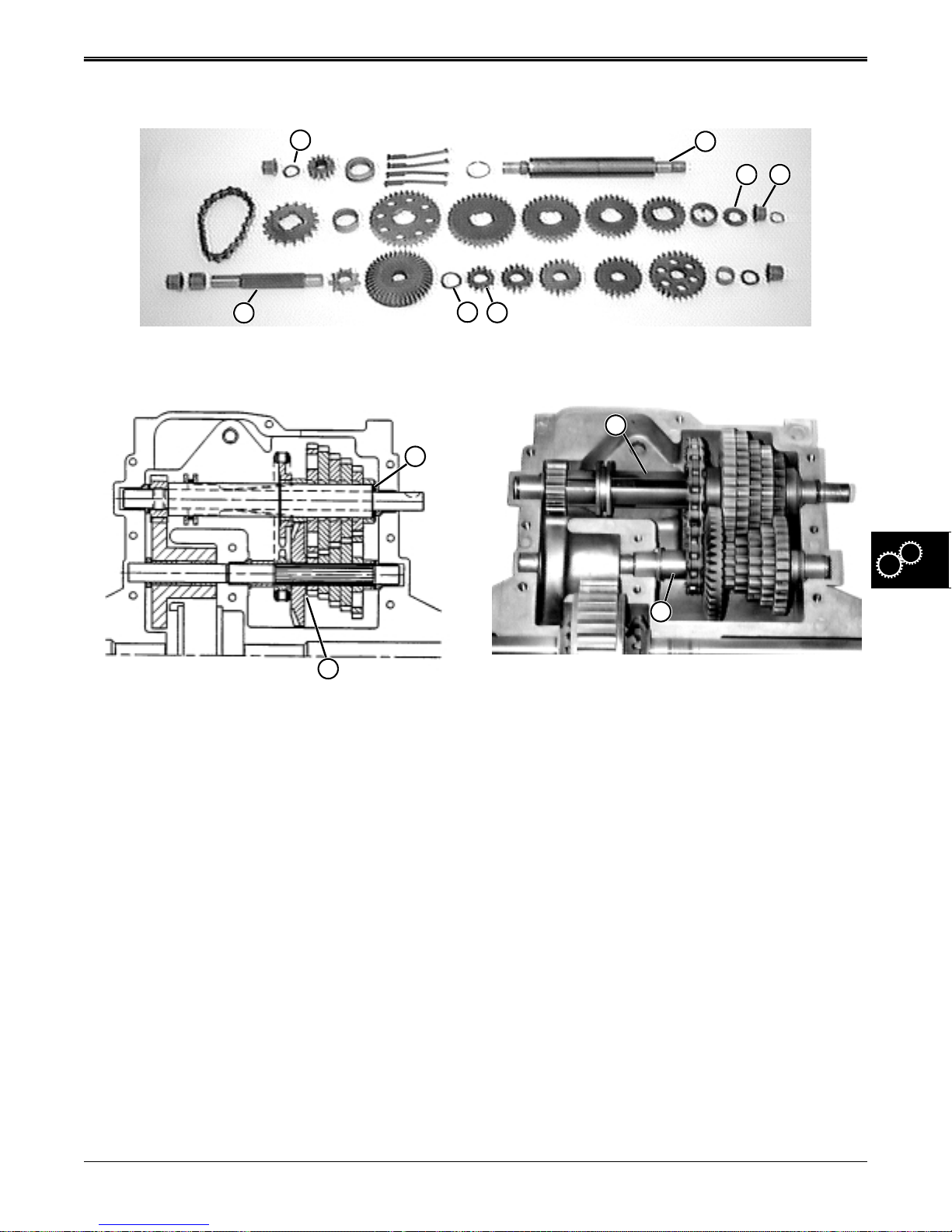
REPAIR GEAR POWER TRAIN
INTERMEDIATE SHAFT & DRIVE
SHAFT REPAIR
A
I
Exploded View
H
E
B D
F
Intermediate & Drive Shaft Inspection:
C
G
1. Inspect overall condition of intermediate shaft and
drive shaft assemblies, including gears for wear,
pitting, broken teeth, etc.
2. For the drive shaft assembly (I), use a feeler gauge
to measure clearance (G) between side surface of
small gear (F) and side surface of shim washer (H):
3. For the intermediate shaft assembly (E), use a
feeler gauge to measure clearance (C) between
end surface of flange bearing (D) and washer (B):
Clearance (G) . . . . . . . . . . . . . . . . . . . . . 0—0.20 mm
(0—0.008 in.)
Clearance (C) . . . . . . . . . . . . . . . . . . . . . 0—0.25 mm
(0—0.010 in.)
4. If either or both clearance measurements are in
excess of specifications shim washers (A) or (H)
need to be added or worn components need to be
replaced.
Intermediate & Drive Shaft Disassembly:
E
I
1. Lift both drive (I) and intermediate (E) shaft
assemblies from transaxle case together.
2. Carefully remove drive shaft assembly components
(bottom row of exploded view) from drive shaft (I).
Be sure to remember each components orientation
to its neighbor and to the drive shaft. Mark the
same side of each component to aid reassembly.
3. Clean components individually once disassembled.
4. Inspect each component closely for wear, scoring,
cracks, chips, and broken teeth or splines.
5. Repeat steps 2 through 4 for the intermediate shaft
(E) and its components (top two rows of exploded
view).
6. Replace components as necessary.
IMPORTANT: Remember gear sets are a matched
set and both must be replaced, even if only one
gear in the set is damaged.
2/12/97 5 - 29
www.servicemanualall.com
Page 81
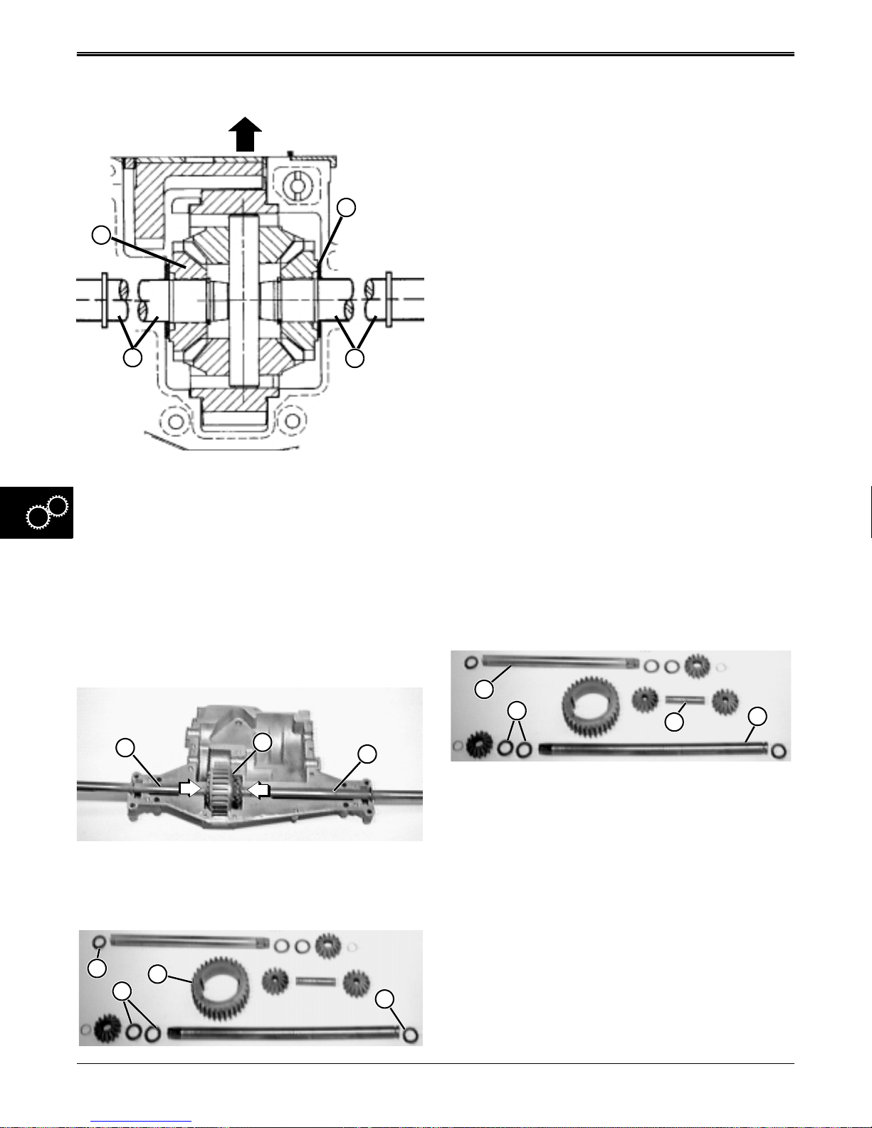
GEAR POWER TRAIN REPAIR
Differential/Axle Shaft Inspection:
A
F
E
Left-Hand
Short Axle
D
Right-Hand
Long Axle
1. Visually check overall condition of assembly.
2. Use a feeler gauge to measure clearance (A)
between side surface of shim washer and side
surface of lower case:
Clearance . . . . . . 0.18—0.38 mm (0.007—0.015 in.),
3. If clearance is excessive, worn or damaged
components must be replaced.
2. Carefully remove axle shaft assembly components
from ring gear (G). Be sure to remember each
components orientation to its neighbor and to the
ring gear (G). Mark the same side of each
component to aid reassembly.
3. Clean components individually once disassembled,
be sure to remove all sealant material from upper
and lower case halves.
4. Inspect each component (especially both upper and
lower case halves) closely for wear, scoring,
cracks, chips, or discoloration (burnt). Replace
components as necessary.
5. Replace seals (I and F) every time transaxle
housing has been separated.
TRANSAXLE ASSEMBLY
IMPORTANT: Maintain absolute cleanliness when
working on transaxle. The close tolerances in
this unit will not tolerate ANY dirt. Use only
clean fresh multipurpose EP grease during
assembly.
IMPORTANT: Coat all mating surfaces, except seal
surfaces, with SAE 30 weight oil before
assembly. Pay close attention to proper order
and orientation of all components. Use a calliper
to identify the correct shim, spacer, or washers
are installed correctly.
Differential/Axle Shaft Assembly:
Differential/Axle Shafts Disassembly:
E
F
D
1. Put inward pressure on both axles (D and E) as you
lift differential assembly (F) from lower case.
I
G
H
F
A
B
C
D
1. Assemble left-hand, short axle (A) as shown with
splined, beveled gear facing the ring gear.
2. Assemble right-hand, long axle (D) as shown with
splined, beveled gear facing the ring gear and shim
washers (B) assembled in combination of
thicknesses to obtain specified air gap (see Inspect
Differential/Axle Shafts Assembly).
3. Assemble internal shaft (C) as shown with beveled
gears facing each other.
4. Install internal shaft assembly in slots of ring gear
and push beveled gears away from each other so
they are ready to mesh with both axle beveled
gears.
5 - 30 2/12/97
www.servicemanualall.com
Page 82
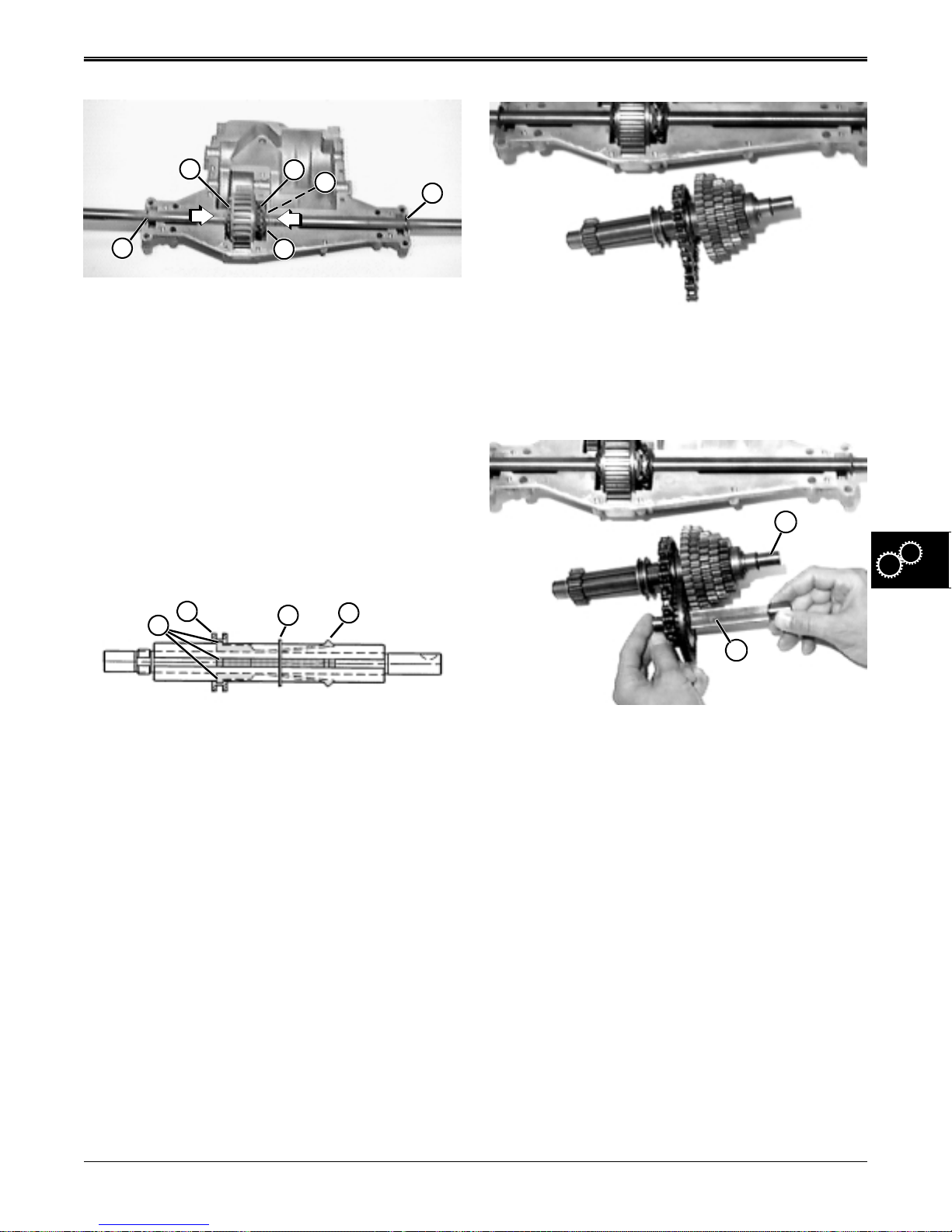
REPAIR GEAR POWER TRAIN
E
I
E
F
H
G
5. Install axle shafts so beveled gears (E) mesh with
differential internal shaft beveled gears.
6. Keep inward pressure on both axles as you install
differential assembly in lower case housing.
7. Measure air gap between shim washers (F) and
side of housing (H). If air gap meets specification
(see Inspect Differential/Axle Shafts Assembly), go
to next step. If air gap does not meet specification,
remove right axle shaft and add other shim washer
combinations until air gap in within specification.
8. Carefully install new axle shaft seals (G and I) and
seat them in their lower case housing grooves.
Assemble Drive/Intermediate Shaft Assemblies:
B
A
C
D
4. Install remaining intermediate shaft components in
their proper order and orientation (reference top
two rows of components in exploded view at the
beginning of this section).
F
I
1. Install retaining ring (C) in intermediate shaft
groove.
2. Install four keys in grooves of intermediate shaft
and hold them so internal shift collar anchors (A)
will seat in internal groove of collar (B) as it is
installed on the shaft.
3. Slide shift collar and keys against retaining ring (C)
and compress locking ramps/lugs (D) to clear
retaining ring.
2/12/97 5 - 31
www.servicemanualall.com
5. Install drive shaft components one at a time from
left-to-right (reference bottom row of components
in photo M42335 at the bottom of this page). Long
flange of small sprocket (J) faces bevel drive gear.
6. Shim washer(s) (E) for intermediate shaft (F) are
found in Shim Kit.
7. Shim washer(s) (H) for drive shaft (I) are found in
Shim Kit.
8. Install new intermediate shaft seal (G) with open lip
facing inside.
Page 83
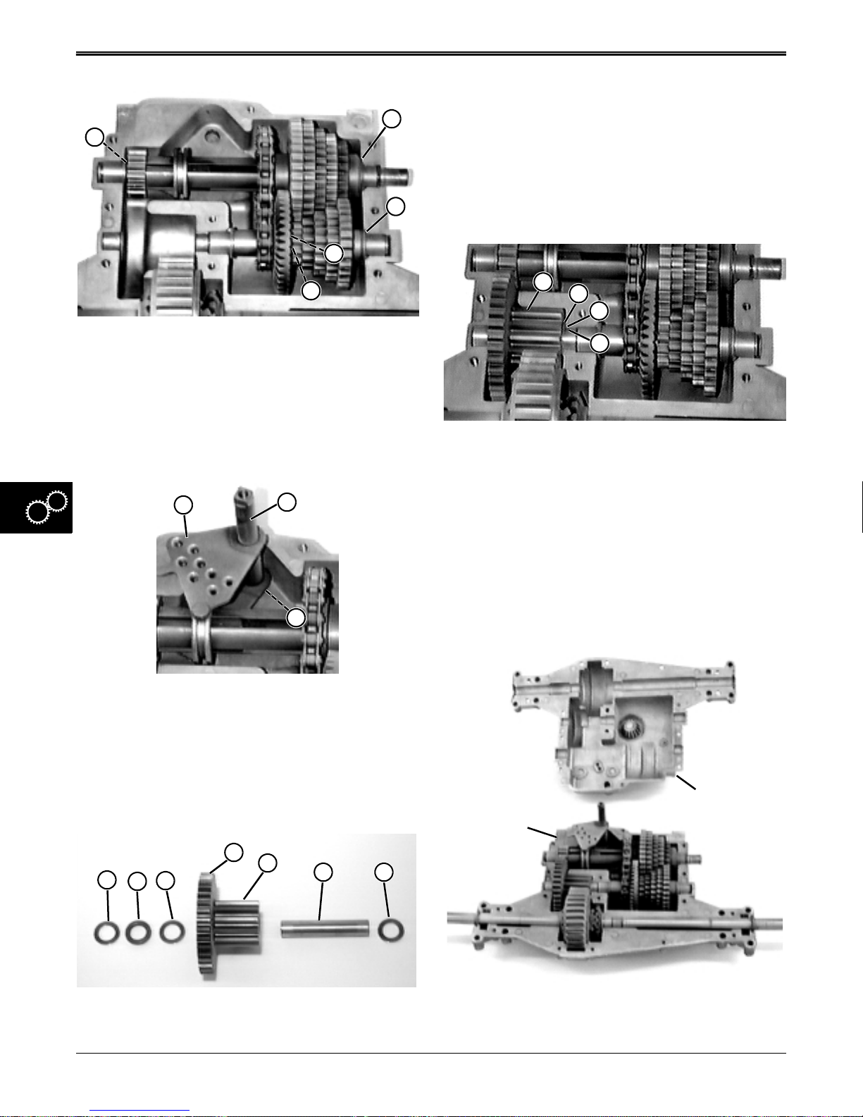
GEAR POWER TRAIN REPAIR
• Washers (A and C) should be 0.632 x 1.00 x 0.026
in.,
K
J
L
M
• Spacer (B) should be 0.630 x 1.00 x 0.169 in.,
• Narrow combination gear (D) should have 35 good
teeth and wide combination gear (E) should have
12 good teeth,
• Idler shaft (F) should be smooth, not scored, worn,
or pitted,
• Shim washer(s) (G) are found in Shim Kit.
N
9. Measure air gaps (K and N)—(see Inspect Drive/
Intermediate Shaft Assemblies). Make any
changes in shim washer (M) thicknesses from
Shim Kit and shim washer (J) thicknesses from
Shim Kit to obtain proper air gaps.
10. When proper air gap is obtained, gears should drag
slightly against feeler gauge.
O
P
Q
H
I
J
K
2. Install idler combination gear assembly (H) into
lower case half.
3. Measure air gap (J) between shim washer (I) and
face of case (K) (see Inspect Idler Combination
Gear Assembly).
4. When proper air gap is obtained, assembly should
drag slightly against feeler gauge.
Assembly Transaxle Housing Case Halves:
11. Apply Never-Seez® to top surface (O) of shifter
plate and contact portions of shifter shaft (P) and
(Q) with upper and lower case halves.
12. Install shifter fork assembly.
Assemble Idler Combination Gear Assembly:
D
E
A
C
B
1. Install components on idler shaft in order shown:
5 - 32 2/12/97
www.servicemanualall.com
F G
Lower Case
Half
Upper Case
Half
Page 84
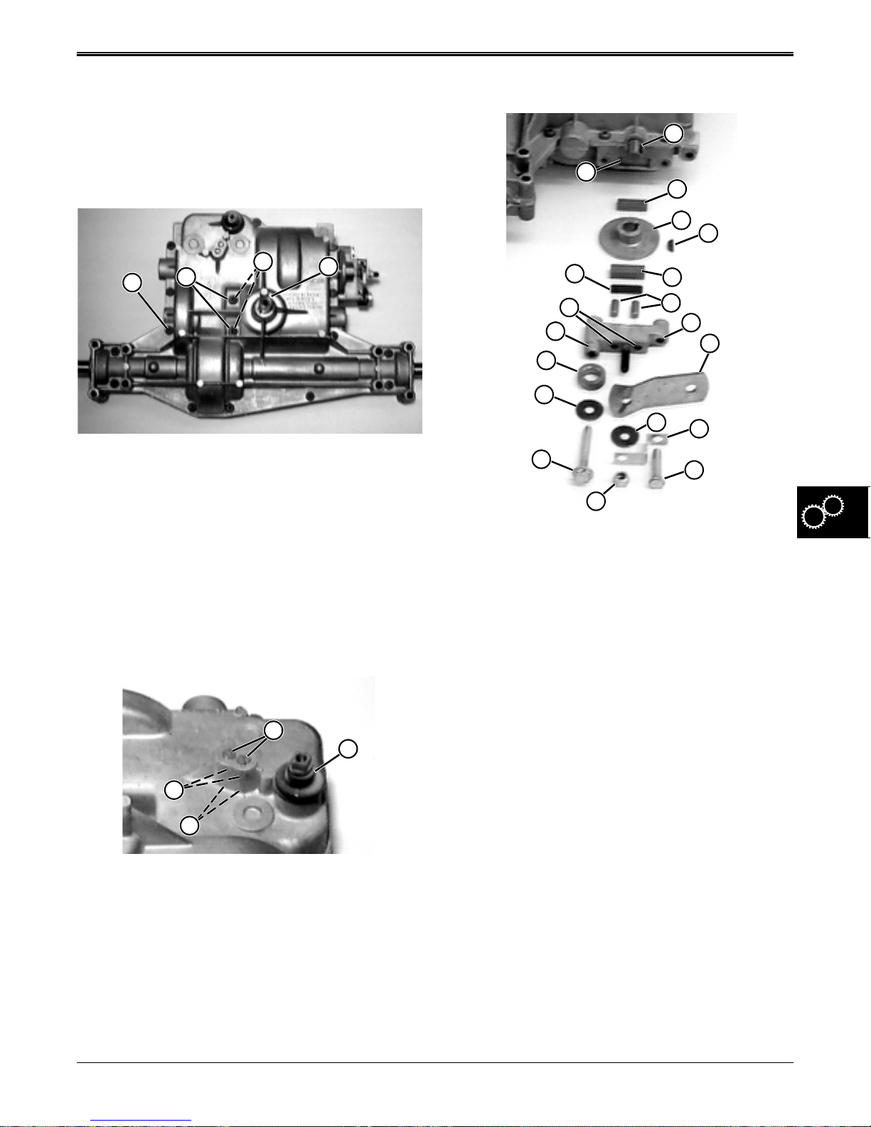
REPAIR GEAR POWER TRAIN
1. Pack upper case beveled pinion gear and lower
case housing assembly with 638 g (1.406 lbs) of
Multi-Purpose EP grease.
2. Apply Form-In-Place Gasket Silicone Sealant to
lower case.
3. BE SURE sealant DOES NOT contact any gear,
shaft, or bearing surfaces.
C
A
B
D
4. Align lower and upper case halves together, be
sure shaft seals are seated correctly and you may
have to turn input shaft (D) slightly to insure
beveled pinon gear meshes with beveled drive
gear.
5. Install 14 outside socket head screws (A) and two
center socket head screws (B) with new rubber
seals (C).
6. Tighten screws to 10 N•m (88 lb-in.).
Install Shifter Detent Assembly:
A
B
D
C
Install Brake Assembly:
A
S
B
C
D
R
Q
P
O
N
M
L
E
F
G
H
I
J
K
1. Install woodruff key (D) into shaft keyway (A).
2. Install thinner friction puck (B) in lower case puck
recess (S).
3. Install brake disc (C) with hub outward.
4. Install spacer (O) over left lip (P) of mounting
bracket.
5. Install long cap screw (M) and washer (N) in left
mounting bracket hole.
6. Install brake lever (H), washer (I), bent bracket (J),
and lock nut (L) on mounting bracket center stud.
7. Install short cap screw (K) in right mounting bracket
hole (G).
8. Install dowel pins (F) inside two center mounting
bracket holes (Q).
9. Install striker plate (R) and thick friction puck (E) in
backside recess of mounting bracket.
IMPORTANT: DO NOT drop or lose detent balls.
1. Install shifter shaft rubber boot (B).
2. Coat detent balls (C) and springs (D) with
Never-Seez and install in case bores.
3. Install and tighten set screws (A) until they are flush
with top of mounting hole surface.
2/12/97 5 - 33
www.servicemanualall.com
Page 85
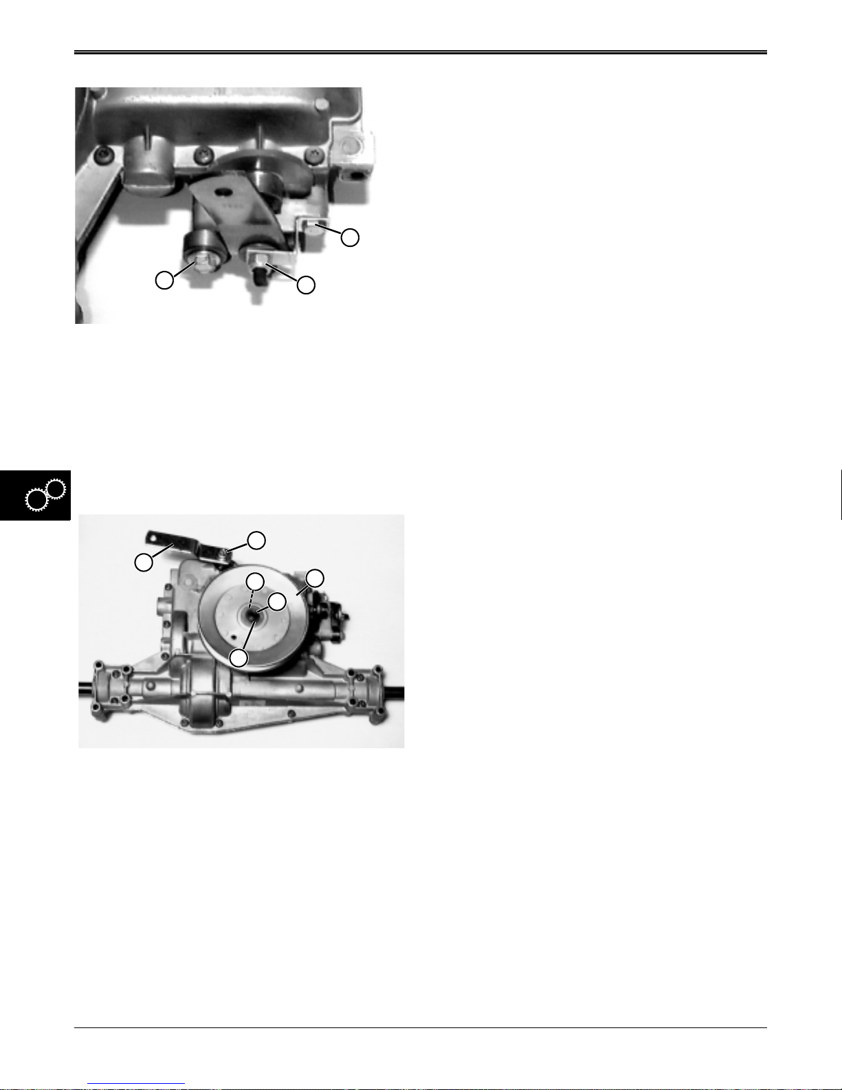
GEAR POWER TRAIN REPAIR
K
M
L
1. Install complete brake assembly to transaxle.
2. Tighten cap screws (K and M) to 20 N•m
(160 lb-in.).
3. Tighten lock nut (L) to specification until there is a
10 mm (0.39 in.) clearance between thick friction
puck and brake disc.
Install Drive Sheave and Shift Arm:
B
A
C
F
D
E
1. Install woodruff key (C) in input shaft (E).
2. Install drive sheave (D) and fasten with snap ring
(F).
3. Install shift arm (A). Tighten cap screw (B) to 16
N•m (140 lb-in.).
NOTE: Be sure when installing that special square
hole washer and shift arm are seated properly
over square end of shifter shaft.
Install Transaxle:
See “TRANSAXLE REMOVAL & INSTALLATION” on
page 23.
5 - 34 2/12/97
www.servicemanualall.com
Page 86
CONTENTS CONTINUED HYDROSTATIC POWER TRAIN
Page
HYDROSTATIC POWER TRAIN
SPECIFICATIONS. . . . . . . . . . . . . . . . . . . . . . . . . . . . . . . . . . . . . . . . . . . 3
REPAIR SPECIFICATIONS . . . . . . . . . . . . . . . . . . . . . . . . . . . . . . . . . . . . . . . . . . . . 4
OTHER MATERIALS. . . . . . . . . . . . . . . . . . . . . . . . . . . . . . . . . . . . . . . . . . . . . . . . . . 5
COMPONENT LOCATION . . . . . . . . . . . . . . . . . . . . . . . . . . . . . . . . . . . . 6
COMPONENT LOCATION—K55 . . . . . . . . . . . . . . . . . . . . . . . . . . . . . . . . . . . . . . . . 6
COMPONENT LOCATION—K55 . . . . . . . . . . . . . . . . . . . . . . . . . . . . . . . . . . . . . . . . 7
COMPONENT LOCATION—K51 . . . . . . . . . . . . . . . . . . . . . . . . . . . . . . . . . . . . . . . . 8
COMPONENT LOCATION—K51 . . . . . . . . . . . . . . . . . . . . . . . . . . . . . . . . . . . . . . . . 9
TRACTION DRIVE SYSTEM COMPONENT LOCATION. . . . . . . . . . . . . . . . . . . . . 10
PEDAL LINKAGE ASSEMBLY COMPONENT LOCATION . . . . . . . . . . . . . . . . . . . 11
SHIFT LINKAGE COMPONENT LOCATION—K–55 TRANSAXLE . . . . . . . . . . . . . 12
SHIFT LINKAGE COMPONENT LOCATION—K–51 TRANSAXLE . . . . . . . . . . . . . 13
THEORY OF OPERATION . . . . . . . . . . . . . . . . . . . . . . . . . . . . . . . . . . . 14
TRACTION DRIVE BELT SYSTEM OPERATION . . . . . . . . . . . . . . . . . . . . . . . . . . 14
TRANSAXLE AND SHIFT LINKAGE SYSTEM OPERATION. . . . . . . . . . . . . . . . . . 14
BRAKE/NEUTRAL RETURN PEDAL COMPONENT LOCATION & OPERATION. . 16
TRANSPORT (FREE-WHEEL) SYSTEM OPERATION—K55 . . . . . . . . . . . . . . . . . 19
TRANSPORT (FREE-WHEEL) SYSTEM OPERATION—K51 . . . . . . . . . . . . . . . . . 20
TROUBLESHOOTING . . . . . . . . . . . . . . . . . . . . . . . . . . . . . . . . . . . . . . 21
DIAGNOSIS. . . . . . . . . . . . . . . . . . . . . . . . . . . . . . . . . . . . . . . . . . . . . . . 24
DIAGNOSIS—K55. . . . . . . . . . . . . . . . . . . . . . . . . . . . . . . . . . . . . . . . . . . . . . . . . . . 26
DIAGNOSIS —K51 . . . . . . . . . . . . . . . . . . . . . . . . . . . . . . . . . . . . . . . . . . . . . . . . . . 28
TESTS AND ADJUSTMENTS . . . . . . . . . . . . . . . . . . . . . . . . . . . . . . . . 30
TRACTION DRIVE SYSTEM. . . . . . . . . . . . . . . . . . . . . . . . . . . . . . . . . . . . . . . . . . . 30
DRIVE BELT ADJUSTMENT. . . . . . . . . . . . . . . . . . . . . . . . . . . . . . . . . . . . . . . . . . . 31
TRANSPORT (FREE-WHEEL) VALVE ADJUSTMENT—K55 . . . . . . . . . . . . . . . . . 31
SHIFT LINKAGE ADJUSTMENT. . . . . . . . . . . . . . . . . . . . . . . . . . . . . . . . . . . . . . . . 32
BELLCRANK SPRING TENSION ADJUSTMENT . . . . . . . . . . . . . . . . . . . . . . . . . . 32
BRAKE SPRING ADJUSTMENT—K55. . . . . . . . . . . . . . . . . . . . . . . . . . . . . . . . . . . 33
BRAKE SPRING ADJUSTMENT—K51. . . . . . . . . . . . . . . . . . . . . . . . . . . . . . . . . . . 34
NOTE: INSPECTION, DISASSEMBLY, AND REPAIR INSTRUCTIONS
SHOWN IN THIS MANUAL ARE FOR OUT-OF-WARRANTY
REPAIRS ONLY.
This transaxle is warranted for 2 years (residential-homeowner
application) or 90 days (commercial application). Should an
internal defect result in a transaxle failure within the warranty
period, John Deere will replace the transaxle assembly.
NOTE: If internal hydro component parts are suspected (after
performing all
SERVICE DEPARTMENT FOR AUTHORIZATION TO REPLACE
TRANSAXLE ASSEMBLY.
2/11/97 6 - 1
www.servicemanualall.com
external checks and adjustments) CALL SABRE
Page 87

HYDROSTATIC POWER TRAIN CONTENTS CONTINUED
REPAIR . . . . . . . . . . . . . . . . . . . . . . . . . . . . . . . . . . . . . . . . . . . . . . . . . .36
TRACTION DRIVE BELT REMOVAL—K55. . . . . . . . . . . . . . . . . . . . . . . . . . . . . . . 36
TRACTION DRIVE BELT REMOVAL—K51. . . . . . . . . . . . . . . . . . . . . . . . . . . . . . . 37
TRACTION DRIVE BELT INSPECTION . . . . . . . . . . . . . . . . . . . . . . . . . . . . . . . . . 37
TRACTION DRIVE BELT INSTALLATION – K55 . . . . . . . . . . . . . . . . . . . . . . . . . . 38
TRACTION DRIVE BELT INSTALLATION—K51. . . . . . . . . . . . . . . . . . . . . . . . . . . 38
TRACTION DRIVE BELT TENSIONING SYSTEM REMOVAL/INSPECTION/INSTAL-
LATION—K55 . . . . . . . . . . . . . . . . . . . . . . . . . . . . . . . . . . . . . . . . . . . . . . . . . . . . 39
POWER TRAIN LINKAGE SYSTEM REMOVAL/INSTALLATION—K55. . . . . . . . . 40
TRANSAXLE REMOVAL AND INSTALLATION—K55 . . . . . . . . . . . . . . . . . . . . . . 41
TRANSAXLE DISASSEMBLY—K55 . . . . . . . . . . . . . . . . . . . . . . . . . . . . . . . . . . . . 42
TRANSAXLE ASSEMBLY—K55 . . . . . . . . . . . . . . . . . . . . . . . . . . . . . . . . . . . . . . . 50
TRANSAXLE INSTALLATION—K55 . . . . . . . . . . . . . . . . . . . . . . . . . . . . . . . . . . . . 55
TRANSAXLE BLEED PROCEDURE—K55 . . . . . . . . . . . . . . . . . . . . . . . . . . . . . . . 55
TRACTION DRIVE BELT TENSIONING SYSTEM REMOVAL/INSPECTION/INSTAL-
LATION—K51 . . . . . . . . . . . . . . . . . . . . . . . . . . . . . . . . . . . . . . . . . . . . . . . . . . . . 56
POWER TRAIN LINKAGE SYSTEM REMOVAL/INSTALLATION—K51. . . . . . . . . 57
TRANSAXLE REMOVAL AND INSTALLATION—K51 . . . . . . . . . . . . . . . . . . . . . . 58
TRANSAXLE EXTERNAL COMPONENTS REMOVAL—K51. . . . . . . . . . . . . . . . . 59
TRANSAXLE INSTALLATION—K51 . . . . . . . . . . . . . . . . . . . . . . . . . . . . . . . . . . . . 60
6 - 2 2/11/97
www.servicemanualall.com
Page 88

SPECIFICATIONS HYDROSTATIC POWER TRAIN
SPECIFICATIONS
Gear Teeth: K–55 K–51
Spur Gear (drive shaft) . . . . . . . . . . . . . . . . 6 teeth 12 teeth
Differential Ring Gear . . . . . . . . . . . . . . . . . 98 teeth 53 teeth
Differential Bevel Pinion Gears
Cross shaft . . . . . . . . . . . . . . . . . . . . . . . 10 teeth 10 teeth
Axle shafts) . . . . . . . . . . . . . . . . . . . . . . . 16 teeth 16 teeth
Drive Belt: K–55 K–51
Effective Length
New . . . . . . . . . . . . . . . . . . . . . . . . . . . . . 2485 mm (97.8 in.) 2400 mm (94.5 in.)
Top Width
New. . . . . . . . . . . . . . . . . . . . . . . . . . . . . 13.11 mm (0.52 in.) 12.7 mm (0.50 in.)
Minimum . . . . . . . . . . . . . . . . . . . . . . . . . 10 mm (0.39 in.) 10 mm (0.39 in.)
Bottom Width
New. . . . . . . . . . . . . . . . . . . . . . . . . . . . . 7.93 mm (0.31 in.) 7.63 mm (0.30 in.)
Minimum . . . . . . . . . . . . . . . . . . . . . . . . . 6 mm (0.24 in.) 6 mm (0.24 in.)
Depth
New. . . . . . . . . . . . . . . . . . . . . . . . . . . . . 9.46 mm (0.37 in.) 8.89 mm (0.35 in.)
Minimum . . . . . . . . . . . . . . . . . . . . . . . . . 7 mm (0.28 in.) 7 mm (0.28 in.)
Lubrication: K–55 K–51
Oil Type. . . . . . . . . . . . . . . . . . . . . . . . . . . . 10W30 Engine Oil, Class CD Factory Sealed
Capacity . . . . . . . . . . . . . . . . . . . . . . . . . . . 1.6 L (1.7 qt) Factory Sealed
Gear Ratios: K–55 K–51
Forward. . . . . . . . . . . . . . . . . . . . . . . . . . . . 25.3:1 28.2:1
Reverse. . . . . . . . . . . . . . . . . . . . . . . . . . . . 25.3:1 28.2:1
Ground Speeds: K–55 K–51
Domestic—Forward . . . . . . . . . . . . . . . . . . 0–8.66 km/hr (0–5.38 mph) 0–8.5 kph (0–5.3 mph)
Reverse. . . . . . . . . . . . . . . . . . . . . . . . . . . . 0–4.24 km/hr (0–2.62 mph) 0–5.3 kph (0–3.3 mph)
Export—Forward. . . . . . . . . . . . . . . . . . . . . 0–7.75 km/hr (0–4.82 mph) 0–8.5 kph (0–5.3 mph)
Reverse. . . . . . . . . . . . . . . . . . . . . . . . . . . . 0–3.80 km/hr (0–2.36 mph) 0–5.3 kph (0–3.3 mph)
Output Torque Rating: K–55 K–51
Rated. . . . . . . . . . . . . . . . . . . . . . . . . . . . . . 196 N•m (145 lb-ft) 231 N•m (170.4 lb-ft)
Maximum. . . . . . . . . . . . . . . . . . . . . . . . . . . 680 N•m (506 lb-ft) 805 N•m (594 lb-ft)
Brake Torque Rating: K–55 K–51
Maximum. . . . . . . . . . . . . . . . . . . . . . . . . . . 196 N•m (145 lb-ft) at 245 N (55 lbs) Brake Arm Force
Rear Axle Loading: K–55 K–51
Maximum. . . . . . . . . . . . . . . . . . . . . . . . . . . 240 kgs (528 lbs) 240 kgs (528 lbs)
2/12/97 6 - 3
www.servicemanualall.com
Page 89

HYDROSTATIC POWER TRAIN SPECIFICATIONS
REPAIR SPECIFICATIONS
Transaxle Components Wear Tolerances: K–55 K–51
Pump (Input) Shaft
Wear Limit. . . . . . . . . . . . . . . . . . . . . . .Visual Check N/A
Motor (Drive) Shaft
Wear Limit. . . . . . . . . . . . . . . . . . . . . . .Visual Check N/A
Axle Shaft Thrust Washers
Wear Limit. . . . . . . . . . . . . . . . . . . . . . .Visual Check N/A
Pump Plate
Wear Limit. . . . . . . . . . . . . . . . . . . . . . .Visual Check N/A
Motor Plate
Wear Limit. . . . . . . . . . . . . . . . . . . . . . .Visual Check N/A
Pump Swashplate Upper Case
Thrust Bushings Minimum. . . . . . . . . . . . 1.3 mm (0.051 in.) N/A
Pump Swashplate Bushing
Wear Limit. . . . . . . . . . . . . . . . . . . . . . . . Visual Check N/A
Pump Swashplate-To- Shifter Blocks
Maximum. . . . . . . . . . . . . . . . . . . . . . . . . 0.15 mm (0.0059 in.) N/A
Axle Shaft-To-Upper Case Bushing
Maximum. . . . . . . . . . . . . . . . . . . . . . . . . 0.5 mm (0.02 in.) N/A
Differential Cross-Shaft-To-Bevel
Pinion Gears Maximum. . . . . . . . . . . . . . 0.5 mm (0.02 in.) N/A
Brake Components Wear Tolerances: K–55 K–51
Brake Disc (Minimum). . . . . . . . . . . . . . . . . .2.5 mm (0.1 in.) N/A
Brake Puck (Minimum) . . . . . . . . . . . . . . . . .8 mm (0.32 in.) N/A
Brake Lever
Minimum . . . . . . . . . . . . . . . . . . . . . . . . . .25 mm (1 in.) N/A
Degrees Forward from Vertical . . . . . . . . .30° 20°
Travel Maximum . . . . . . . . . . . . . . . . . . . .30° 30°
TORQUE SPECIFICATIONS K–55 K–51
Brake Lever Bracket Cap Screws. . . . . . . . 55 N•m (40 lb-ft.) 55 N•m (40 lb-ft.)
Case Cap Screws
New Case . . . . . . . . . . . . . . . . . . . . . . . . 30 N•m (264 lb-in.) 30 N•m (264 lb-in.)
Used Case. . . . . . . . . . . . . . . . . . . . . . . . 27 N•m (243 lb-in.) 27 N•m (243 lb-in.)
Center Block Cap Screws. . . . . . . . . . . . . . 55 N•m (40 lb-ft.) N/A
Drain Plug . . . . . . . . . . . . . . . . . . . . . . . . . . 19 N•m (168 lb-in.) N/A
Pump Port Connector . . . . . . . . . . . . . . . . . 24 N•m (217 lb-in.) N/A
Pump Port Connector Pipe Plug . . . . . . . . . 8 N•m (72 lb-in.) N/A
Pump Port Plug. . . . . . . . . . . . . . . . . . . . . . 24 N•m (217 lb-in.) N/A
Reservoir Cover Cap Screws . . . . . . . . . . . 29 N•m (260 lb-in.) N/A
6 - 4 2/12/97
www.servicemanualall.com
Page 90

SPECIFICATIONS HYDROSTATIC POWER TRAIN
OTHER MATERIALS
Transaxle Housing Case Half Sealant: K–55 K–51
Form-In-Place Silicone N/A
Gasket Sealant
Pump Connector Pipe Plug Sealant: K–55 K–51
. . . . . . . . . . . . . . . . . . . . . . . . . . . . . . . . . . Pipe Sealant With Teflon® N/A
. . . . . . . . . . . . . . . . . . . . . . . . . . . . . . . . . . Approved Teflon® Sealant Tape N/A
Lubrication: K–55 K–51
Type . . . . . . . . . . . . . . . . . . . . . . . . . . . . . . 10-W-30 Class-CD Factory Sealed
2/12/97 6 - 5
www.servicemanualall.com
Page 91

HYDROSTATIC POWER TRAIN COMPONENT LOCATION
COMPONENT LOCATION
COMPONENT LOCATION—K55
1. Axle Shaft/Wheel Key (2 used) 49. Spacer (M10x20x20)
2. Left Axle Shaft 50. Cap Screw (M10x60) (3 used)
3. Left Axle Shaft Seal 51. Pump Filter
4. Left Axle Shaft Bushing 52. Motor Plate Dowel Pin (2 used)
5. Upper Case Housing 53. Pump Plate
6. O-Ring 54. Rolled Pins (M12x22) (2 used)
7. Fill Cap 55. Pump and Motor Center Block
8. Snap Ring 56. Motor Plate
9. Input Shaft Seal 57. Motor Cylinder Block
10. Snap Ring 58. Motor Piston Spring (5 used)
11. Ball Bearing 59. Motor Piston Washer (5 used)
12. Snap Ring 60. Motor Piston (5 used)
13. Cap Screw (M8x20) (4 used) 61. Motor Swashplate Bearing
14. Vent Valve Cap 62. Motor Fixed Swashplate Housing
15. Vent Valve 63. Spring
16. Reservoir Cover 64. Snap Ring
17. Brake Friction Puck Shims 65. Ball Bearing
18. Brake Friction Puck 66. Motor Output Shaft (6 teeth)
19. Brake Disc (splined) 67. Ball Bearing
20. Brake Lever 68. Silicone Sealant
21. Cap Screw (M10x45) (2 used) 69. Debris Magnet
22. Brake Lever Mounting Bracket 70. Magnet Seal
23. Right Axle Shaft Bushing 71. Motor Output Shaft Seal
24. Right Axle Shaft Seal 72. RH Axle Bushing
25. Right Axle Shaft 73. LH Axle Bushing
26. Shifter Shaft O-Ring 74. Lower Case Housing
27. Shift Block (2 used) 75. O-Ring
28. Shifter Shaft 76. Drain Plug
29. Left Axle Shaft Thrust Washer 77. Cap Screw (Self-Tapping) (M8x30) (17 used)
30. Left Axle Shaft C-Ring Retainer 78. O-Ring
31. Left Axle Shaft Differential Bevel Pinion Gear (16 teeth) 79. Bleed Port Connector
32. Differential Ring Gear (98 teeth) 80. Pipe Plug
33. Differential Cross Shaft Block 81. O-Ring
34. Differential Cross Shaft Bevel Gear (10 teeth) 82. O-Ring
35. Right Axle Shaft Differential Bevel Pinion Gear (16 teeth) 83. Pump Port Plug
36. Right Axle Shaft C-Ring Retainer 84. O-Ring
37. Right Axle Shaft Thrust Washer 85. Transport Bypass Valve Actuating Pin
38. Differential Cross Shaft Bevel Gear (10 teeth) 86. Transport Bypass Valve Actuating Bracket
39. Pump Swashplate Upper Case Thrust Bushing (2 used) 87. E-Ring
40. Pump Swashplate 88. Transport Bypass Valve Push Pin (2 used)
41. Pump Swashplate Bushing 89. Transport Bypass Valve Spring (2 used)
42. Pump Swashplate Bearing 90. Transport Bypass Valve Push Pin Guide (2 used)
43. Pump Input Shaft 91. Transport Bypass Valve Body (2 used)
44. Pump Piston (5 used) 92. O-Ring (2 used)
45. Pump Piston Washer (5 used) 93. Ball (2 used)
46. Pump Piston Spring (5 used) 94. Ball Holder (2 used)
47. Pump Cylinder Block 95. Spring (2 used)
48. Pump Plate Dowel Pin (2 used) 96. Spring Holder (2 used)
6 - 6 2/12/97
www.servicemanualall.com
Page 92
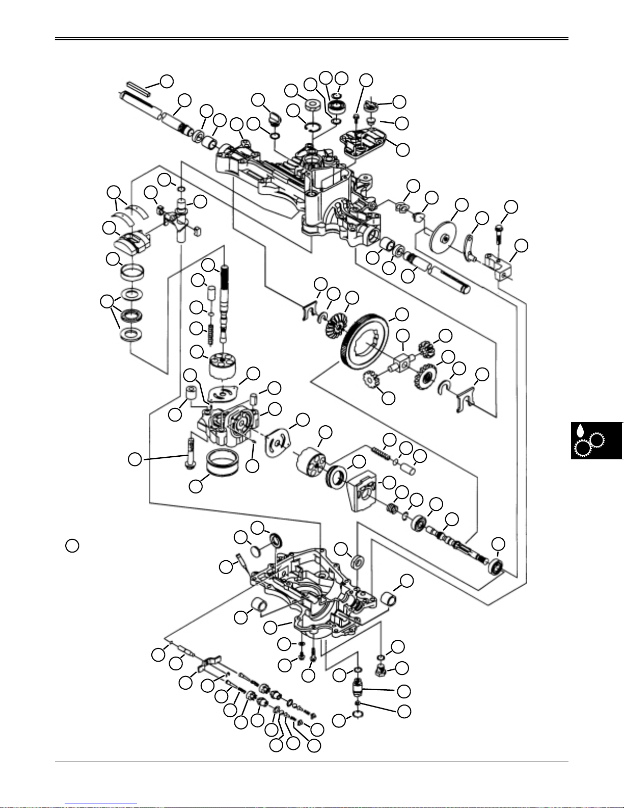
COMPONENT LOCATION HYDROSTATIC POWER TRAIN
COMPONENT LOCATION—K55
11
1
2
3
4
7
6
5
10
9
8
12
27 N•m (20 lb-ft.)
13
14
15
16
26
39
40
41
42
40 N•m
27
49
50
(30 lb-ft.)
New Case: 31 N•m (278 lb-in.)
77
Used Case: 27 N•m (243 lb-in.)
48
45
46
47
51
44
28
43
68
69
52
53
70
54
55
56
29
57
30
71
31
61
23
24
38
58
62
32
33
63
59
72
25
17
64
60
18
65
34
35
66
36
19
20
37
67
21
22
57 N•m
(42 lb-ft.)
84
85
86
87
2/12/97 6 - 7
www.servicemanualall.com
73
19 N•m
(168 lb-in.)
88
89
90
91
74
92
93
75
76
94
77
95
96
78
81
82
83
24 N•m (217 lb-in.)
24 N•m (217 lb-in.)
79
80
8 N•m (72 lb-in.)
Page 93

HYDROSTATIC POWER TRAIN COMPONENT LOCATION
COMPONENT LOCATION—K51
1. Knob
2. 1/4X20 Hex Jam Nut
3. Rod
4. E-Ring
5. M6X30 Bolt
6. Snap Ring
7. Spacer
8. Sheave
9. Fan
10. Flnage Lock Nut
11. Lock Nut
12. Screw
13. Screw
14. Strap
15. Push Nut
16. Screw (R.H. Side)
Screw (L.H. Side Not Shown)
17. Transmission Assembly
6 - 8 2/12/97
www.servicemanualall.com
Page 94
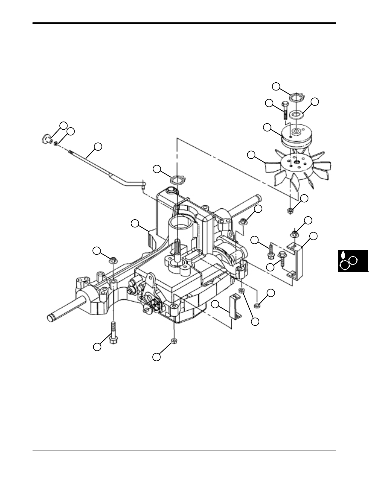
COMPONENT LOCATION HYDROSTATIC POWER TRAIN
COMPONENT LOCATION—K51
6
5
1
2
3
4
17
11
8
9
11
12
13
7
10
11
14
16
New Case: 27.4-31.4 N•m (20-23 lb-ft.)
Used Case: 22.5-27.4 N•m (16-20 lb-ft.)
2/12/97 6 - 9
www.servicemanualall.com
15
14
11
11
Page 95
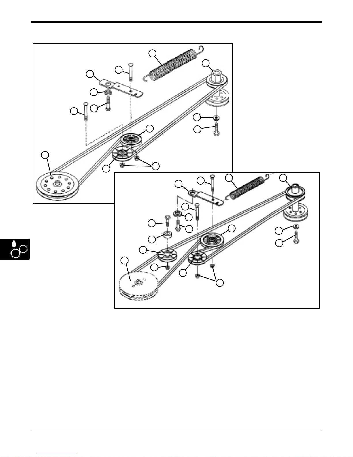
HYDROSTATIC POWER TRAIN COMPONENT LOCATION
TRACTION DRIVE SYSTEM COMPONENT LOCATION
6
14
17
5
12
16
11
4
9
10
18
13
5
16
7
8
3
7
15
1
8
K–55 TRANSAXLE
6
17
14
12
13
K–51 TRANSAXLE
1. Transaxle Drive Sheave (K55)
2. Transaxle Drive Sheave (K51)
3. Arm (K55)
4. Arm (K51)
5. Bolt M8 x 45
6. Spring
7. Bushing
2
11
8. Cap Screw
9. Bolt (K51)
10. Spacer (K51)
11. Flange Nut M8
12. Lock Washer
13. Cap Screw
14. Sheave, Engine
18
11
15. Bolt M8 x 45
16. Idler
17. Idler
18. Idler (K51)
6 - 10 2/12/97
www.servicemanualall.com
Page 96
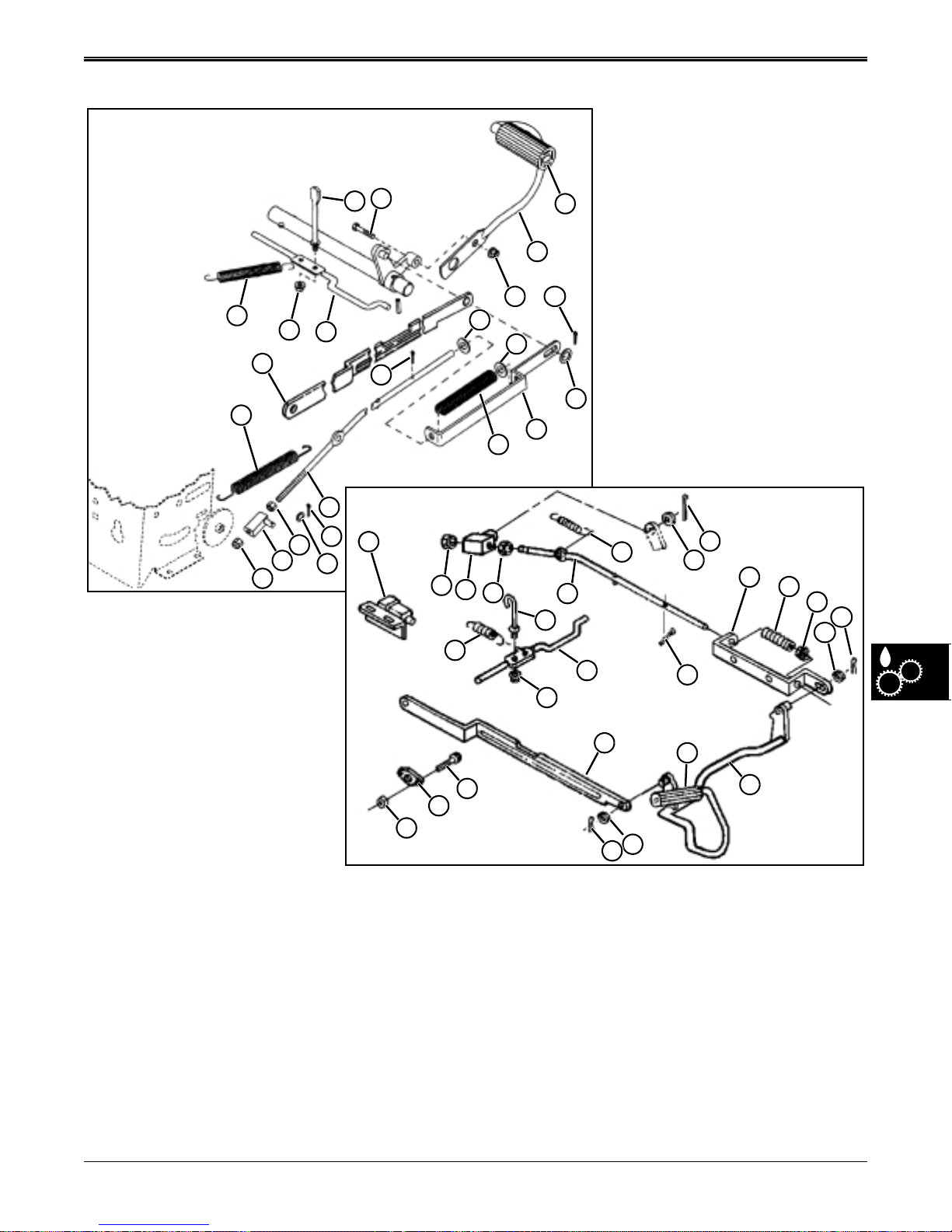
COMPONENT LOCATION HYDROSTATIC POWER TRAIN
PEDAL LINKAGE ASSEMBLY COMPONENT LOCATION
16
13
12
17
14
15
21
8
7
11
11
10
18
19
K–55 TRANSAXLE
7
6
9
2
K–51 TRANSAXLE
1. Neutral Switch
2. Lock Nut, 9.525mm
3. Pivot
4. Nut, 3/8 in.
5. Rod
6. Washer
7. Cotter Pin
8. Brake Rod Return Spring
5
7
4
3
1
6
2
3
4
13
22
23
24
9. Brake Spring Strap
10. Brake Compression Spring
11. Washer
12. Park Brake Lever
13. Extension Spring
14. Flange Nut
15. Rod, Parking Brake
16. Cap Screw, M8x35 (K55)
12
14
8
5
15
21
6
7
17. Lock Nut M8 (K55)
18. Brake Pedal (K55)
19. Pad
20. Shaft, Brake (K51)
21. Strap, Return to Neutral
22. Screw, M8x20 (K51)
23. Bracket (K51)
24. Lock Nut, M8 (K51)
19
7
6
9
10
11
7
6
7
20
2/12/97 6 - 11
www.servicemanualall.com
Page 97
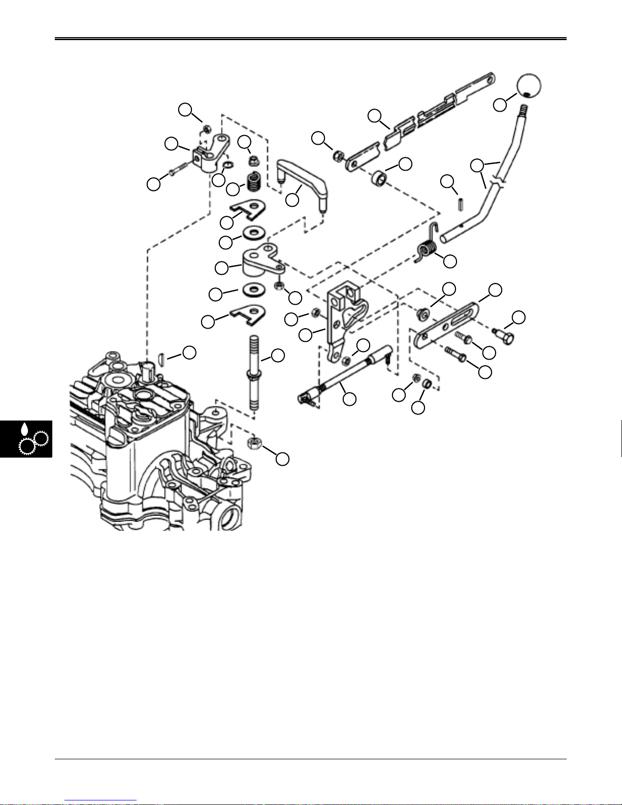
HYDROSTATIC POWER TRAIN COMPONENT LOCATION
SHIFT LINKAGE COMPONENT LOCATION—K–55 TRANSAXLE
3
2
1
28
27
26
4
34
33
31
30
29
22
5
32
25
24
23
20
6
8
9
11
12
19
18
17
7
10
13
14
15
16
1. Cap Screw (M6x20)
2. Shift Arm
3. Lock Nut (M6)
4. Lock Nut (M10)
5. Flange Nut (M8)
6. Return-To-Neutral Strap
7. Shift Knob
8. Neutral Return Bushing
9. Rolled Pin (M4x20)
10. Shift Lever
11. Shift Lever Neutral Return
Spring
12. Spacer
21
13. Support Strap
14. Shoulder Bolt
15. Cap Screw (M10x25)
16. Cap Screw (M8x25)
17. Spacer
18. Flange Nut (M8)
19. Lock Nut (5/16-24 UNF 3B)
20. Shift Link Ball Joint Assembly
21. Flange Nut (M8)
22. Mounting Stud (M10x76.5-Top/
M8x40-Bottom)
23. Shift/Return-To-Neutral Bracket
24. Flange Nut (M8)
25. Lock Nut (5/16-24 UNF 3B)
26. Woodruff Key (5/32x5/8 in.)
27. Anchored Washer
28. Friction Disc
29. Bellcrank
30. Friction Disc
31. Anchored Washer
32. Shift Link
33. Tensioning Spring
34. Snap Ring
6 - 12 2/12/97
www.servicemanualall.com
Page 98
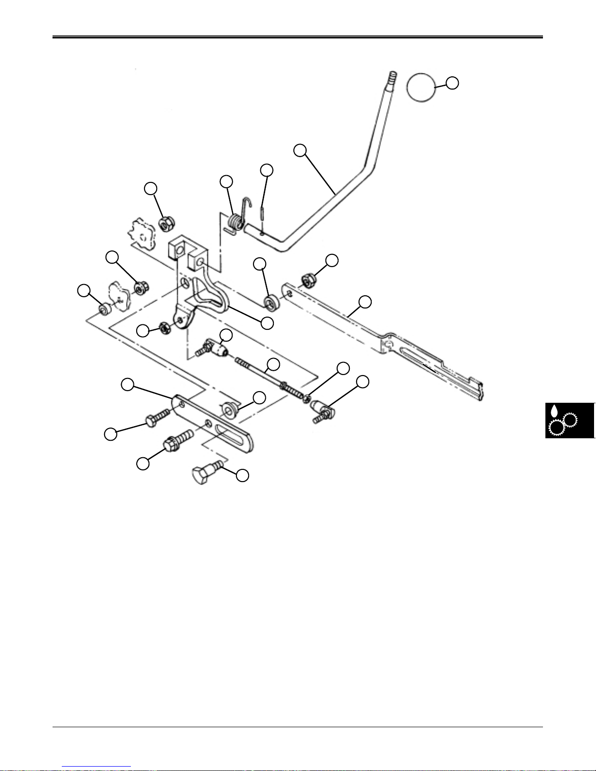
COMPONENT LOCATION HYDROSTATIC POWER TRAIN
SHIFT LINKAGE COMPONENT LOCATION—K–51 TRANSAXLE
4
3
2
21
1
20
19
18
17
16
15
1. Torsion Spring
2. Spring Pin (4 x 20 mm)
3. Gearshift Lever
4. Knob
5. Lock Nut
6. Strap
7. Roller
7
8
9
10
13
14
8. Bracket
9. Ball Joint
10. Stud, Adjusting
11. Nut, (5/16”)
12. Ball Joint
13. Bushing
14. Shoulder Bolt
5
6
11
12
15. Screw M10 x x25
16. Screw M8 x 25
17. Support
18. Lock Nut (5/16-24 UNF 3B)
19. Spacer
20. Flange Nut, M8
21. Flange Nut, M10
2/12/97 6 - 13
www.servicemanualall.com
Page 99
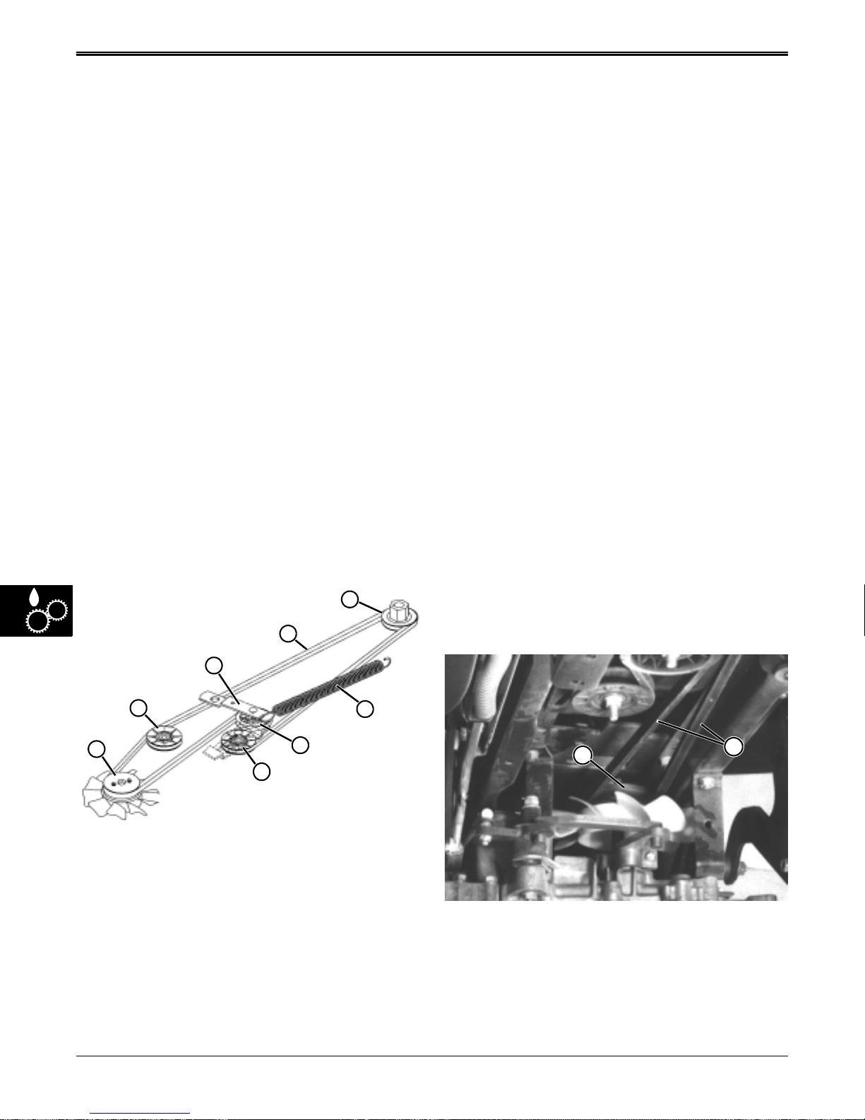
HYDROSTATIC POWER TRAIN THEORY OF OPERATION
THEORY OF OPERATION
In this group the Sabre hydrostatic power train is
separated into the following systems:
• Traction Drive Belt System
• Transaxle and Shift Linkage System
• Brake/Neutral Return Pedal System
• Transport (Free-Wheeling) System
TRACTION DRIVE BELT SYSTEM
OPERATION
Function:
The traction drive belt transfers power from the engine
to the input pulley of the hydrostatic transaxle.
Major Components:
• Foot pedal and brake linkage
• Engine drive sheave
• Traction drive belt
• Tensioning idler assembly
• Tensioning spring
• Adjusting idler assembly
• Transaxle drive sheave
Theory of Operation:
B
A
TRANSAXLE AND SHIFT LINKAGE
SYSTEM OPERATION
Function:
The function of the transaxle is to transfer power from
the traction drive belt system (driven by the engine), to
the rear wheels, and allow the operator to select
ground speed and direction.
The drive belt turns the transaxle input pulley, and
drives the transaxle’s hydrostatic pump. When the
hydrostatic drive is in neutral, no pressure is built up in
the pump. When the operator pushes the hydrostatic
drive lever forward, the shift linkage tilts the swash
plate, inside the transaxle, off center, and the pump
pistons build pressure which drives the hydrostatic
motor. The motor drives the rear axle and wheels
through the differential assembly.
The transaxle provides infinite ground speed selections
up to 5 mph in forward and up to 2.6 mph in reverse.
Major Components:
• Transaxle input pulley and fan
• Pump (input) shaft and cylinder block assembly
• Shift linkage and pump swashplate assembly
• Center block assembly
• Motor cylinder block assembly and drive shaft
• Differential assembly and axle shafts
• Wheels and tires.
Theory of Operation:
(D) Used with
K-51 Only
D
C
The traction drive belt (A) is driven by the upper pulley
of the engine drive sheave (B). The traction belt then
transmits engine power to the input pulley of the
hydrostatic transaxle (C). On the K-51 transaxle only,
an additional idler pulley (D) is used between the
engine sheave and the transaxle. The traction drive
belt is tensioned by the tension idler (E), which is
mounted on a spring loaded bracket (F). The tension
spring (G) runs forward and hooks to the frame. When
the traction drive belt stretches beyond the range of the
spring loaded tension idler, an adjustable idler (H) can
be moved in slots on the frame, allowing the tension
idler to move back into range.
F
G
E
H
C
Neutral:
When the engine is running, the traction drive belt (A)
turns the transaxle input pulley (C), cooling fan, and
input shaft. The input shaft turns the hydrostatic pump
input shaft and pump body, inside the transaxle.
A
6 - 14 2/12/97
www.servicemanualall.com
Page 100
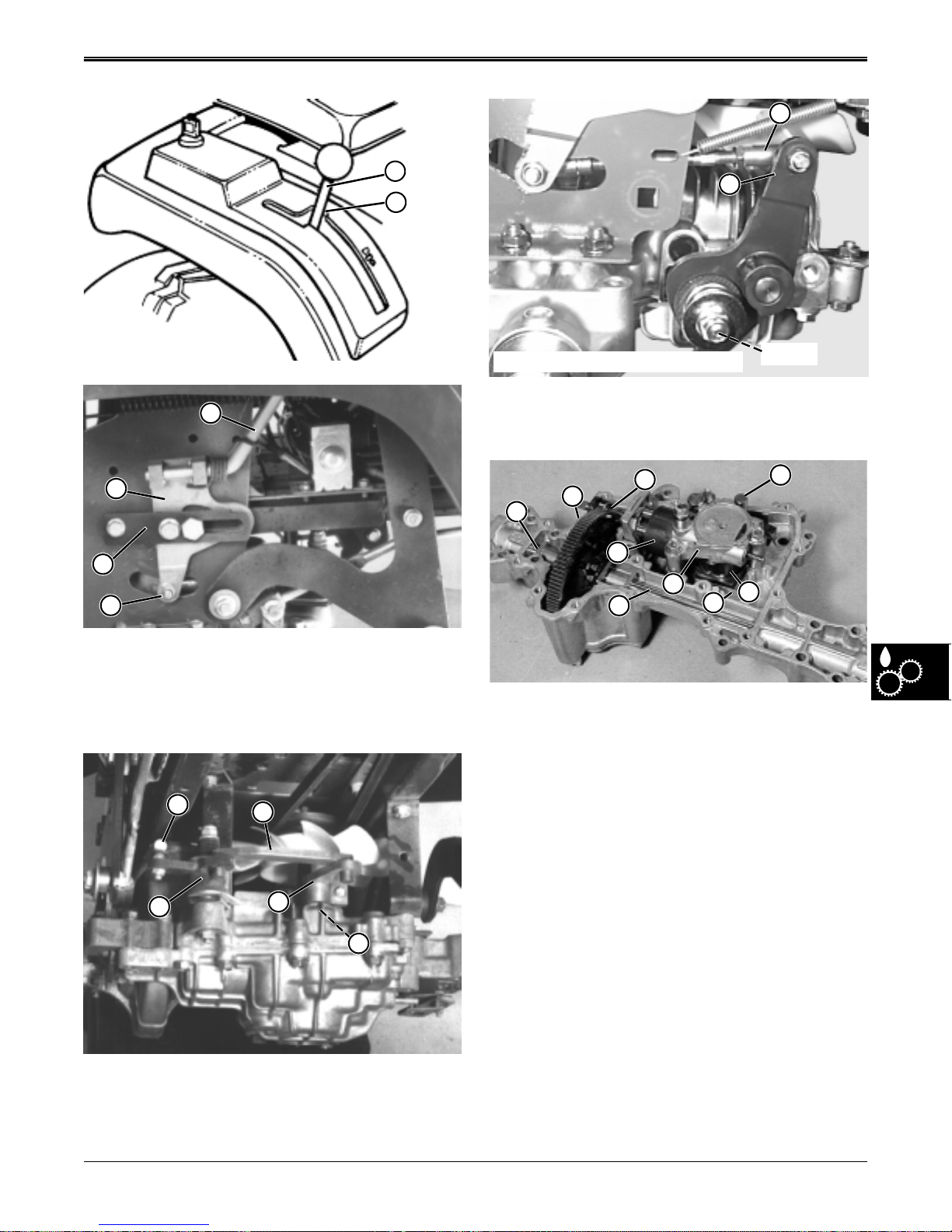
THEORY OF OPERATION HYDROSTATIC POWER TRAIN
M
I
J
R.H. Frame Rail Removed For Clarity
P
Shaft
On the K-51 transaxle, the turnbuckle link (M) moves
I
the transaxle shift lever (P). The shift lever turns the
transaxle shifter shaft.
K
K
L
M
L
M
Q
P
R
O
J
N
When the hydrostatic drive lever (I), is in the neutral
position (J), the shift bracket (K) is centered in it’s
mounting bracket (L), and the turnbuckle link (M) is
centered in the slot on the right side frame.
M
N
O
P
Q
On the K-55 transaxle, the turnbuckle link (M) moves
the bellcrank (N), link strap (O), and transaxle shift
lever (P). The shift lever turns the transaxle shifter
shaft.
K55
When in neutral, the shift linkage holds the shifter shaft
(J) and the variable-angle pump swashplate (O) in the
neutral position. While in neutral (level) position, the
pump cylinder block (N) rotates with the pump (input)
shaft but does not pump any oil into the motor half of
the center block (P) because the pump pistons are not
moving up and down as they rotate. Therefore, the
motor cylinder block (Q) does not turn nor do the motor
(output) shaft (M), differential assembly (L), or drive
axles (K and R).
2/12/97 6 - 15
www.servicemanualall.com
 Loading...