

Page 1
OPERATING GUIDE
Version 4
Models:
SWM3000
SWM1600
WARNING : DON’T WORRY!
Every other wireless microphone manual has to warn
users about the perils of feedback with wireless mics.
Welcome to Sabine True Mobility Wireless Systems,
where the only feedback we get is how good it sounds!
Page 2

Page 3

Declaration of Conformity
DECLARATION OF CONFORMITY
Application of Council Directive: 73/23/EEC and 89/336/EEC
Standards to which conformity is declared:
EN 60065: 1993
EN 60950: 1992
EN 55103-1: 1997
EN 55022: 08:94 + a1:05:05
EN 55103-2: 1997
ETS 300445 (VHF)
ETS 300442 (UHF)
Manufacturer's Name: Sabine, Inc.
Manufacturer's Address: 13301 Highway 441
Alachua, FL 32615 USA
Type of Equipment: Wireless microphone/receiver
Model No.: True Mobility Wireless Systems
Serial No.:
Year of Manufacture: 1999 following
I, the undersigned, hereby declare that the equipment specified above conforms to the above
Directive and Standard.
Place: Alachua, Florida, USA Signature:
Date: January 4, 2002 Full Name: Doran Oster, Sabine President
Page 4

Table of Contents
Table of Contents
SECTION ONE : INTRODUCTION ....................................................................... 6
1.1 Using this Operating Guide ........................................................................................... 6
1.2 System Description ........................................................................................................6
1.3 System Features............................................................................................................. 7
SECTION TWO : FRONT & BACK PANEL VIEWS............................................. 8
2.1 Back Panel View ............................................................................................................. 8
2.2 UHF Front Panel View .................................................................................................... 8
2.3 VHF Front Panel View .................................................................................................... 8
SECTION THREE : SYSTEM COMPONENTS ..................................................... 9
3.1 Handheld Microphone ................................................................................................... 9
3.2 Beltpack Transmitter ......................................................................................................9
3.3 Model Numbers and Accessory Part Numbers............................................................ 9
SECTION FOUR : QUICK SETUP ...................................................................... 10
4.1 Receiver & Transmitter Quick Setup ........................................................................... 10
4.2 FBX Quick Setup ........................................................................................................... 10
SECTION FIVE : RECEIVER & TRANSMITTER SETUP ...................................11
5.1 Multiple Units ................................................................................................................ 11
5.1.1 Number of Simultaneous Systems ..................................................................................................... 11
5.1.2 Antenna Dividers & Extension Antennas ........................................................................................... 11
5.2 Receiver Placement and Connections ....................................................................... 11
5.2.1 Power Cords & Antennas ........................................................................................................................... 11
5.2.2. Receiver Placement.................................................................................................................................... 11
5.2.3 Audio Output Connection........................................................................................................................... 12
5.2.4 Beltpack Headset/Lavalier Microphone connection .................................................................... 13
5.3 Transmitter & Receiver Operating Procedures .......................................................... 13
5.3.1. Start-up Procedures .................................................................................................................................... 13
5.3.2. Transmitter LED Indicators ....................................................................................................................... 14
5.4 Group & Channel Selection ......................................................................................... 15
5.4.1 Selecting Transmitter/Receiver Groups/Channels ....................................................................... 15
5.4.2 Group/Channel Selection (Multiple Receivers/Transmitters) ..................................................... 15
5.5 Audio Output Settings.................................................................................................. 16
5.5.1 Unbalanced Audio Output........................................................................................................................... 16
5.5.2 Balanced Audio Output ................................................................................................................................16
5.6 Transmitter Battery Installation ................................................................................... 16
5.6.1 Battery Usage ................................................................................................................................................ 16
5.6.2 Handheld Microphone (SW30-H, SW16-H) ....................................................................................... 17
5.6.2 Beltpack Transmitters (SW30-TX, SW16-TX) ................................................................................. 17
5.7 Dual Battery Charger ................................................................................................... 18
4
Page 5

Table of Contents
SECTION SIX : FBX FEEDBACK EXTERMINATOR ......................................... 19
6.1 Introduction to FBX ...................................................................................................... 19
6.2 Two FBX Advantages................................................................................................... 20
6.2.1 Advantage #1 .................................................................................................................................................... 20
6.2.2. Advantage #2 ................................................................................................................................................... 20
6.3 Who Needs The FBX? .................................................................................................. 21
6.4 FBX Setup & Ready Mode ........................................................................................... 21
6.4.1 FBX Fixed & Dynamic filters ..................................................................................................................... 21
6.4.2 Default FBX filter settings .......................................................................................................................... 22
6.4.3 FBX filter width ................................................................................................................................................ 22
6.5 How To Set Up The FBX Section Of Your True MobilityTM System.......................... 22
6.6 Bypass Button.............................................................................................................. 23
SECTION SEVEN : DE-ESSER SET UP ............................................................ 24
7.1 The Essence of De-essing............................................................................................ 24
7.2 Using the De-esser........................................................................................................ 24
SECTION EIGHT : COMPRESSOR SET UP...................................................... 25
8.1 Basics of Compression ............................................................................................... 25
8.2 Using the Compressor................................................................................................. 25
8.3 Suggested Compressor Settings ............................................................................... 26
8.3.1 Vocal Compression ...................................................................................................................................... 26
8.3.2 Guitar Compression ..................................................................................................................................... 26
8.3.2 Additional Settings .......................................................................................................................................... 26
8.4 Possible Compression Trouble Areas ........................................................................ 27
SECTION NINE : TIPS AND TROUBLESHOOTING .......................................... 28
9.1 Tips for Maximum Performance of your True Mobility Wireless System ................. 28
9.2 Troubleshooting ...........................................................................................................28
SECTION TEN : MULTIPLE FREQUENCY & USE CHARTS............................. 29
10.1 UHF Frequency Code U922A [USA] ......................................................................... 29
10.2 UHF Frequency Code U808C [Export] .................................................................... 30
10.3 UHF Frequency Code U794A [Export] ..................................................................... 30
10.4 VHF Frequencies [USA] ............................................................................................. 31
10.5 VHF Frequencies [Export] ......................................................................................... 32
SECTION ELEVEN : APPENDICES ................................................................... 33
11.1 FBX Configuration DIP Switch .................................................................................. 33
11.2 Beltpack Transmitter Connector Wiring Diagrams .................................................. 34
11.3 XLR Connector ............................................................................................................ 35
11.4 Beltpack Transmitter Schematic ................................................................................ 35
11.5 Engineering Specifications........................................................................................ 36
SECTION TWELVE : CAUTIONS & WARRANTY.............................................. 38
INDEX ................................................................................................................... 40
Sabine True Mobility Wireless Operating Guide Version 4
Models: SWM3000 & SWM1600
© 2003 Sabine, Inc.
B1-SWM-Op-Guide-v4.pmd 030108-hto
5
Page 6

Section One : Introduction
SECTION ONE : INTRODUCTION
Congratulations on purchasing a Sabine True Mobility™ Wireless System. True Mobility™ Wireless
Systems give you all the built-in processing you need on every microphone.
1.1 Using this Operating Guide
This operating guide covers all Sabine True Mobility™ Wireless Systems — model numbers SWM3000
and SWM1600 — and contains full explanations for everything you need to operate your True Mobility™ Wireless system.
Section 2 shows front and back panel views for your True Mobility Wireless receiver.
Section 3 lists system components.
Section 4 gives the Quick Setup procedures for Receiver & Transmitter Operation and using the
FBX Feedback Exterminator®. Note that there is also a quick-start label on top of your
True Mobility receiver for the Sabine FBX Feedback Exterminator®, Compressor/Limiter
and De-Esser functions.
Section 5 details receiver and transmitter installation and setup.
Section 6 explains the how and why of Sabine’s FBX technology, and gives a complete understand-
ing of how to set up your FBX filters.
Section 7 details the True Mobility’s De-Esser.
Section 8 explains the use of the Compressor.
Section 9 gives tips on how to get the best performance from your Sabine Wireless, and describes
some possible operating problems and their solutions.
Section 10 has frequency charts for all currently available Sabine Wireless systems.
Section 11 contains information on how to modify your True Mobility’s FBX filters (NOTE: these
procedures are to be performed by qualified personnel only), transmitter wiring
schematics, and engineering specifications for your Sabine Wireless.
Section 12 states caution and warranty information for your True Mobility™ Wireless system.
1.2 System Description
Sabine True Mobility™ Wireless Systems come in UHF and VHF models, with many accessories to
complete your system packages. Both systems include state-of-the-art Phase Locked Loop (PLL)
synthesized transmitter and receivers, True Diversity reception, dual-squelch circuitry, excellent noise
rejection and superior dynamic range. Microphone transmitter configurations consist of handheld,
lavalier, or headset styles. Sabine True Mobility™ Wireless UHF and VHF systems offer optional
front or rear mount antennas, extension antennas, and antenna divider systems.
Sabine Wireless Systems are superior to conventional systems because we include the two most
comprehensive features found in any wireless system: True Mobility and Targeted Input Process-
ing.
We call our system True Mobility because it provides the freedom you should expect from a wireless
system. With a conventional wireless system, your range of movement is limited by the potential for
feedback in acoustical “hot spots.” Some areas are so feedback prone you cannot go near them at all.
Other areas allow only minimal gain before feedback occurs. Until now, freedom from mic cables
meant more likelihood for feedback.
Fortunately, that has changed. Sabine’s True Mobility system includes our patented, industry-standard FBX Feedback Exterminator®. Your microphones will sound loud and clear without feedback,
and with a greatly increased area of feedback-free movement. This is the freedom you were seeking
when you chose a wireless system.
Sabine’s True Mobility doesn’t stop with automatic feedback control. Conventional wireless systems
require the added cost of outboard equalizers, compressor/limiters, and de-essers to maximize performance.
6
Page 7

Section One : Introduction
Sabine offers a different approach: on-board processing at no extra cost, all dedicated to one
microphone. We call this Targeted Input Processing. With Targeted Input Processing, no mic gets
more processing than it needs, and every mic gets precise, targeted control perfectly suited to provide
optimal performance.
1.3 System Features
All Digital Targeted Input Processing
• Patented FBX Feedback Exterminator®: The industry standard in automatic feedback control.
The True Mobility FBX function includes our fast Turbo Setup Mode, 10 FBX filters, and easy-to- use
controls.
• Auto De-Esser: Sabine’s new automatic de-essing algorithm senses, tracks, and removes sibi-
lance without affecting the rest of your program.
• Compressor: Our famous digital compressor offers the gain management you need to compensate
for all types of performers and speakers, from those who are shy around microphones, to the
boldest worship leader. You can adjust ratio, threshold and attack settings.
True Diversity Receiver
• Phase Locked Loop (PLL): Receiver and transmitter are synthesizer controlled via PLL circuitry.
• Dual-squelch Circuitry: Sabine 2-stage squelch utilizes Tone Key and Noise squelch systems
which eliminate interference and provide quiet, reliable and flexible service.
• Dual-NiMH 9-volt Battery Charger: on-board dual-NiMH 9-volt battery charger means you are
never out of power for handheld transmitters—saves you hundreds of dollars a year in 9-volt battery
costs! Transmitter low-battery warning light lets you know when to change. Sabine’s NiMH batter-
ies give you up to 5 hours of battery life and only MINIMAL MEMORY EFFECT! *
• Radio Frequency (RF) and Audio signal meters: Bright, easy-to-see-and-read level meters
keep you informed of signal strength and audio level.
• User-friendly Channel (and Group for UHF) Selection on Transmitters: The RF signal meter
helps you find a clear frequency.
• Options include: Rear-to-Front Antenna Converter Kit, Antenna Divider Systems, Extension An-
tennas and Extension Antenna Boosters (Extension Antenna Booster raises the signal +13 dB and
requires use of Antenna Divider).
NOTE: MEMORY EFFECT typically occurs when a NiCAD rechargeable battery is recharged
*
before reaching the end of its initial charge. The battery remembers the charge state prior
to being recharged and uses that as its “empty” charge state. Sabine NiMH batteries are
“memory resistant.” You can recharge your batteries any time you please; whether they
are 1/2, 3/4 or almost fully charged. You will always get consistent battery life from your
Sabine NiMH batteries (for up to 500 charges or more).
B1-SWM-Op-Guide-v4.pmd 030108-hto
7
Page 8
Section Two : Front & Back Panel Views
SECTION TWO : FRONT & BACK PANEL VIEWS
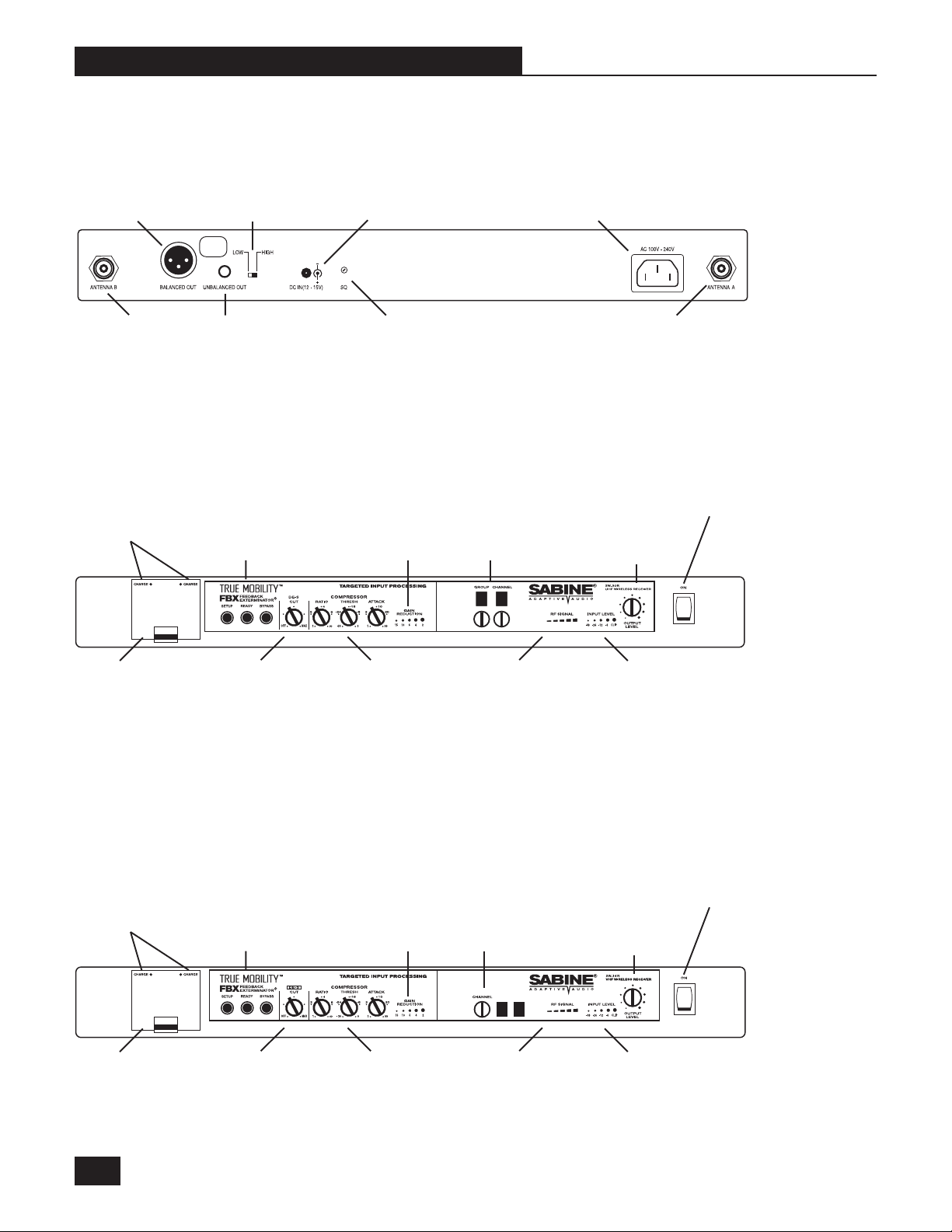
2.1 Back Panel View
Balanced Out
Antenna B
Unbalanced
Output Level Switch
MIC
LEVEL
ONLY
Unbalanced Out
2.2 UHF Front Panel View
Charge
Indicator LEDs
FBX Feedback
Exterminator Control
DC Power IN
Squelch adjustment
Gain Reduction
Indicator Lights
Group & Channel
Selectors
AC Power IN
Antenna A
Power &
Power LED
Output Level
Control
Dual-Battery
Charger
Compartment
WARNING:
Do not attempt to recharge alkaline or other
non-rechargeable batteries. Non-rechargeable
batteries will explode if placed in a battery
charger. For best results, use Sabine 7.2-volt
rechargeable batteries (SWABAT).
De-Esser Compressor
2.3 VHF Front Panel View
Charge
Indicator LEDs
Dual-Battery
Charger
Compartment
FBX Feedback
Exterminator Control
De-Esser Compressor
Gain Reduction
Indicator Lights
RF Signal
Indicator
Lights
Channel
Selector
RF Signal
Indicator
Lights
Input Level
Indicator
Lights
Power &
Power LED
Output Level
Control
Input Level
Indicator
Lights
8
Page 9
Section Three : System Components
SECTION THREE : SYSTEM COMPONENTS
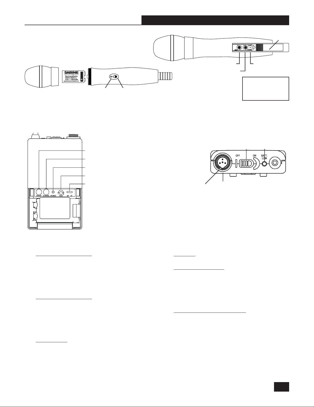
3.1 Handheld Microphone
NOTE: Use only Sabine 7.2-volt
Rechargeable or 9-volt Alkaline battery
3.2 Beltpack Transmitter
LED
Group Selector*
Channel Selector
Indicates unused frequency
Gain
Power SwitchPower/Battery
Antenna
Group Selector
Channel Selector
SlotGuitar/Mic Switch
Mini XLR
Connector
Sliding Door
Indicates
frequency not
available
NOTE: SWM1600 VHF
microphones and transmitters do not have a
GROUP selector.
Low
Power
Switch
Battery
Indicator
*NOTE: SWM1600 VHF micro-
phones and transmitters do not
have a Group selector.
3.3 Model Numbers and Accessory Part Numbers
SWM3000 UHF System
SWM3000-H UHF Handheld Package (SW30-R, SW30-H)
SWM3000-LX UHF Lavalier Package (SW30-R, SW30-TX, SWT42L-4PX)
SWM3000-DX UHF Headset Package (SW30-R, SW30-TX, SWT25W-4PX)
SW30-R 30-Ch Diversity Receiver with Battery Charger
& NiMH rechargeable battery
SW30-H Condenser PLL Hand Held Microphone
SW30-TX PLL Belt Pack Transmitter, 4-pin Mini XLR
SWM1600 VHF System
SWM1600-H VHF Handheld Package (SW16-R, SW16-H)
SWM1600-LX VHF Lavalier Package (SW16-R, SW16-TX, SWT42L-4PX)
SWM1600-DX VHF Headset Package (SW16-R, SW16-TX, SWT25W-4PX)
SW16-R 16-Ch Diversity Receiver with Battery Charger
& NiMH rechargeable battery
SW16-H Condenser PLL Hand Held Microphone
SW16-TX PLL Belt Pack Transmitter, 4-pin Mini XLR
Microphones
SWT42L-4PX Unidirectional Lavalier Microphone, 4-pin Mini XLR
SWT25W-4PX Unidirectional Headset Microphone, 4-pin Mini XLR
SWT30G-4PX Guitar Plug and Cable, 4-pin Mini XLR
Batteries
SWBBAT Rechargeable 7.2-volt NiMH Battery for transmitters
Antenna Accessories
SWA100 TNC Rear to Front Antenna Converter Kit
SWA4V VHF 4-Channel Antenna Divider System
SWAVEXT VHF Extension Antenna (1 set of 2)
SWA4U UHF 4-Channel Antenna Divider System
SWAUEXT UHF Extension Antenna (1 set of 2)
SWAUB UHF Extension Antenna Booster *
SWAEXTM Mounting Bracket for Extension Antenna (1 set of 2)
Mic & Transmitter Accessories
SWC200 Condenser Microphone Capsule Module
SWCCLIP-H Handheld Microphone Holder
SWCTRI Desktop microphone tripod
SWC4P 4-pin connector
SWCCLIP-L Mic clip for SWT42L-4PX Lav Mic
SWCSCR2 Windscreen for Lav Microphones
Extension Antenna Booster requires use of Antenna
*
Divider.
B1-SWM-Op-Guide-v4.pmd 030108-hto
9
Page 10

Section Four: Quick Setup
SECTION FOUR : QUICK SETUP
4.1 Receiver & Transmitter Quick Setup
Please read Section Five Receiver & Transmitter
Setup for a complete understanding of how to set up your
True Mobility Receiver.
1. Place the receiver in an open area within visual range
of the intended microphone locations. Note that the
range of your microphones is about 100 meters, but
that structural objects can lessen that range.
2. Turn the Output Level of the receiver and mixer in use
to the minimum setting.
3. Connect the unbalanced output (1/4 inch jack) of your
True Mobility receiver to the unbalanced input of your
mixer or amplifier; or the balanced output (XLR connector) of your receiver to the balanced mic input of
your mixer or amplifier.
NOTE: when putting the unbalanced output of the receiver into the Line In input jack of a mixer or amplifier,
switch the receiver’s Level Switch to the High position
(see p.10, Fig. 5d). If you connect the unbalanced output of a receiver into the Mic-In input jack of a mixer or
amplifier; switch the receiver’s Level Switch to the Low
position.
4. Turn on Receiver. Set receiver and transmitter to
same Group and Channel. Make sure your transmitter is turned off.
5. Check that the RF Signal LEDs are not lighting up.
If RF Signal LEDs light up before transmitter is turned
on, choose another frequency.
6. Turn on wireless microphone or transmitter. Check that
the REF Signal LEDs are lit.
7. Adjust volume.
a. Speak into the microphone. Adjust the transmitter
Gain until Input Level LEDs (on receiver) light without clipping. NOTE: Step 7.a is for beltpack transmitters only—the Transmitter Gain is not adjustable on handheld microphones.
4.2 FBX Quick Setup
Please read Section 6.6 How to Set Up the FBX Section of your True Mobility System for a complete un-
derstanding of the FBX function and control.
1. Patch the Sabine receiver into your mixer or amp and
position the speakers; then turn on the receiver, transmitter, and microphone. Look for strong RF signal on
the front panel meter; check microphone and adjust
Output Level for strong input level on the mixer or
receiver’s amp.
2. Position the microphone in the primary area of use;
press and hold the Setup button on the receiver until
the Setup indicator flashes 4 times, then release. Do
not use microphone for performance in this mode.
Do not talk into microphone until setup is complete.
3. Slowly raise the gain on the mixer or amp channel
until FBX eliminates the first few feedback tones. Stop
raising gain.
4. Move the microphone to another area of use and slowly
raise gain until FBX eliminates a few more feedback
tones.
5. Repeat step 4 until the Setup indicator automatically
goes off and the Ready indicator comes on.
You may quit Setup mode at any time prior to its
automatic exit by simply pressing the Ready button.
NOTE : The Bypass button bypasses only the FBX filters, and not the additional signal processing (de-essing
and compression) available in the Targeted Input Processing section of the Sabine True Mobility
ceiver.
TM
Wireless Re-
b. Adjust the receiver Output Level to approximately
the 12 o’clock position (or loud enough to supply a
strong input level to the mixer or amplifier).
c. Adjust the volume control of the amplifier and/or
mixer to an appropriate sound level.
10
Page 11
Section Five: Receiver & Transmitter Setup
SECTION FIVE : RECEIVER & TRANSMITTER SETUP
Each Sabine Wireless System consists of a transmitter and a receiver. Sabine’s True Mobility Wireless
receivers are True Diversity receivers—that means they have two fully redundant receivers listening for your
transmitter and trading off automatically to whichever receives the best signal.
5.1 Multiple Units
5.1.1 Number of Simultaneous Systems
UHF receivers/transmitters have 30 frequencies to choose from, but there is a maximum number that can
be used in one location (see Section Ten: Multiple Frequency & Use Charts for more information and
setup). VHF receivers/transmitters have 16 frequencies to choose from. These also have a maximum
number that can be used on one location. UHF and VHF systems can be used together to increase the
number of units. Refer to your receiver Frequency Code and the corresponding information in Section Ten:
Multiple Frequency & Use Charts for how to set up multiple receivers and transmitters.
5.1.2 Antenna Dividers & Extension Antennas
When multiple UHF or VHF systems are in use, a Sabine antenna divider (UHF systems: SWA- 4U; VHF
systems: SWA- 4V) can be used to minimize the number of antennas. Extension antennas can be added to
maintain good reception even when receivers are far from transmitters.
5.2 Receiver Placement and Connections
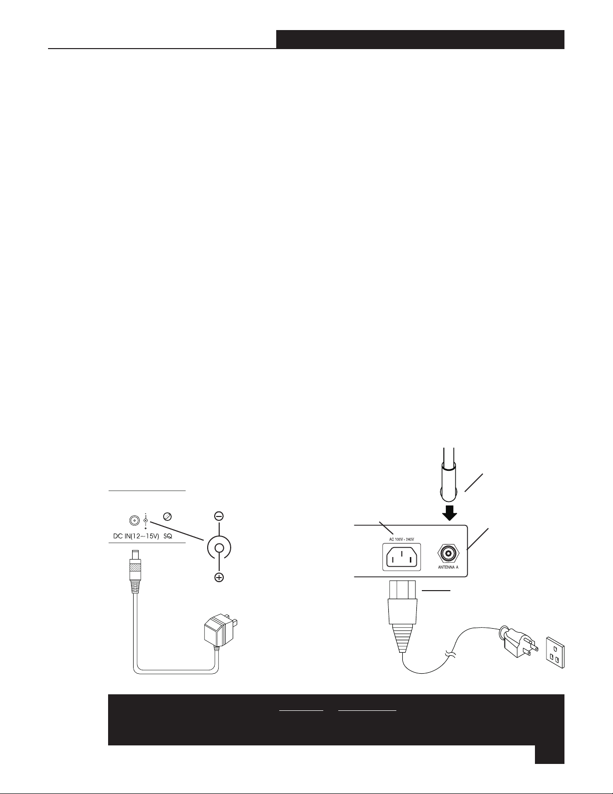
5.2.1 Power Cords & Antennas
Attach the power cord to the AC Power IN on the back panel and to a 120 - 240-volt AC power source
(alternatively, you may use a 12-15 VDC, 0.6A, 10W power adapter as in Figure 5b). Attach antennas or
antenna connectors to the antenna A & B TNCs on the True Mobility back panel.
5.2.2. Receiver Placement
The receiver should be placed in an open area within visual range of the intended microphone location. Note
that the range of your transmitter is about 100 meters, but that structural objects can lessen that range.
Extension antennas can be added to maintain good reception even when the receiver is located far from the
transmitter.
Antenna A
Figure 5b - DC Power Connections
AC Power IN
Figure 5a - AC Power and Antenna Connections
Antenna A TNC
Receiver-side AC
Power cord
CAUTION: Do not use third party receivers or transmitters as part of, or in conjunction with
your Sabine Wireless system. Some third party microphone and pickups can be configured
to work with the Sabine True Mobility. See Appendix 11.2 for wiring diagrams.
B1-SWM-Op-Guide-v4.pmd 030108-hto
11
Page 12
Section Five: Receiver & Transmitter Setup
CAUTIONS
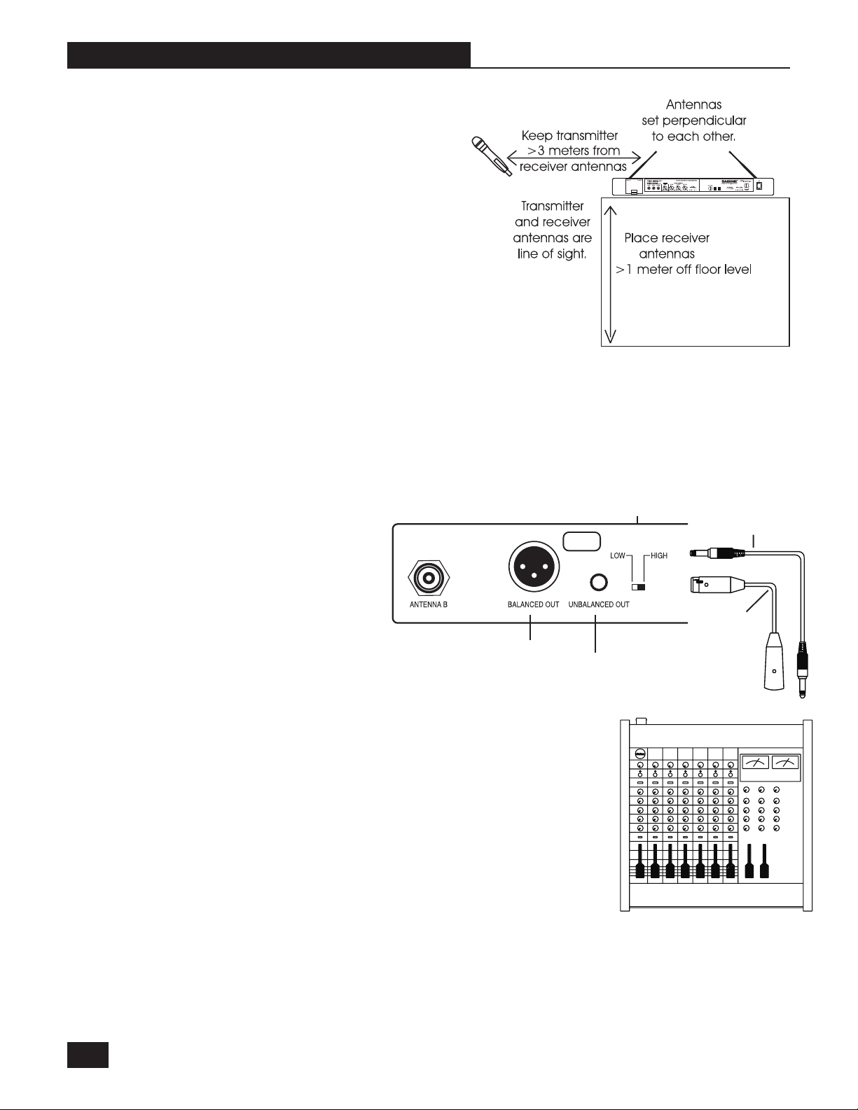
- Since the installation of the antennas influences the operating efficiency of the receiver,
the most important rule is to minimize the distance between receiving antenna and transmitter for better reception and performance.
- Keep the system away from electrical-noise
sources (electric motors, refrigerators, arc
welders, etc.). Place the receiver at least one
meter above floor level. Keep all transmitters
at least 3 meters away from a receiver antenna.
Your True Mobility receiver can be installed into an EIA standard rack-mount case using the rack-mount
brackets provided. A Rear-to-Front Antenna Converter Kit (SWA100) is available to improve reception on
rack-mounted receivers.
5.2.3 Audio Output Connection
Connect the unbalanced output (1/4 inch jack) of your True Mobility receiver to the unbalanced mic input
of your mixer or amplifier; or the balanced output (XLR connector) of your receiver to the balanced mic
input of your mixer or amplifier.
NOTE 1 : The Level Switch affects only the Unbalanced Output on the receiver. In the “Low”
position, the output is the same
as the Balanced (XLR) output.
In the “High” position, the output
is 10 dB higher than the XLR output.
*
See Section Ten for allowable
*
Figure 5c - Receiver &
Antenna Placement
MIC LEVEL
ONLY
Balanced Output (XLR)
Unbalanced Output (¼-inch)
Figure 5d - Audio Output Connection (mic level only)
distance between transmitter
and receiver.
Level Switch
Unbalanced Output
Cord (¼-inch)
Balanced
Output Cord
(XLR)
12
NOTE 2 : Guitar Output: Using ¼-inch jack cable, plug one end into
the receiver’s unbalanced output and the other end to the input of a
guitar amplifier. Switch the Level Switch to the High position.
Mixer or Amplifier
Page 13

Section Five: Receiver & Transmitter Setup
5.2.4 Beltpack Headset/Lavalier Microphone connection
Plug the Headset or Lavalier connector into the 4-pin threaded connector located on top of the UHF of
VHF beltpack transmitter. Be careful to align the notch on the inside of the cord connector with the slot on
the inside of the beltpack connector.
Low
1. Hold cord-side of the connector
here with index finger and thumb,
and place on top of beltpack receptacles.
2. While gently pushing to connect, rotate entire connector
until notches & slots
align, and connector
slides into place.
Slot
Power
Switch
Mini XLR
Connector
Battery
Indicator
3. Lock in place with
screw-on sleeve.
Tighten finger-tight.
Screw-on Sleeve
Figure 5f - Connector Placement
NOTE: See Section 11.2 Beltpack Transmitter
Connector Wiring Diagrams for Sabine True Mobility connector wiring information.
5.3 Transmitter & Receiver Operating Procedures
5.3.1. Start-up Procedures
1. Power up the True Mobility receiver. The red LED on the power switch will indicate power is on.
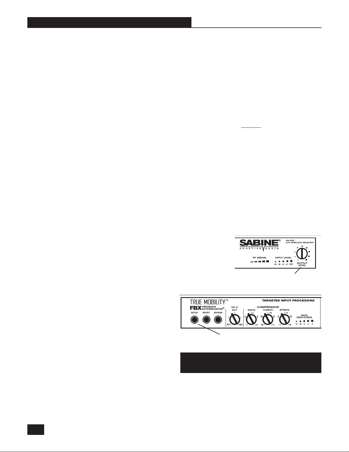
2. Check RF Signal indicator
LEDs. Other signal sources,
including other wireless communication devices and transmitters, can interfere with the
operation of your receiver. Before turning on your microphone or beltpack transmitter,
check to see if any of the RF
Figure 5g - Receiver Controls & LEDs
RF Signal LEDs Audio Input LEDs
Signal LEDs on the receiver
are lit. The number of LEDs that light up will indicate the strength of the interference.
NOTE: Some interference can be dealt with using Sabine’s two-stage squelch. Adjust the Squelch
control knob (“SQ” on rear panel of unit) clockwise until all RF Signal LEDs go out.
Power On
Indicator light
CAUTION: Increasing the squelch threshold will
shorten the operating distance possible between
microphone and receiver. A much better solution
is to use the Group and Channel selectors to locate a frequency without interference or with minimal interference.
3. Power up your mixer and or amplifier. Turn volume
controls to the minimum setting.
MIC LEVEL
ONLY
Squelch
Figure 5h - Receiver Back Panel Squelch Control
B1-SWM-Op-Guide-v4.pmd 030108-hto
13
Page 14

Section Five: Receiver & Transmitter Setup
4. Turn on your Sabine Wireless microphone or beltpack transmitter.
Select the same Group/Channel as the receiver (see Section 5.4 Group & Channel Selection).
Under normal circumstances, the RF Signal indicator on the receiver will light up when a transmitter
is turned on within operating range of that receiver.
NOTE: The Sabine Wireless receiver has a two-stage squelch system that allows you to turn on or
off your transmitter while the receiver and sound system are on—without causing pops or clicks
from the Sabine Wireless system.
5. Speak into the microphone. When audio program is added to that RF signal, the Input Level indica-
tors will light up in accordance with the strength of the audio signal. Adjust transmitter Gain to
maximum signal without clipping (NOTE: Handheld microphones do not have gain control).
6. Adjust mixer and amplifier levels.
5.3.2. Transmitter LED Indicators
Sabine True Mobility transmitters incorporate multifunction LED indicators. These LEDs signify a
variety of information depending on when and for
how long they are lit.
Power/Battery LED
The handheld microphone has an LED next to the
Power Switch (Figure 5i), and one inside the Group/
Channel Selector compartment (Figure 5k). The
Figure 5i - Handheld Microphone Power/Battery LED
Beltpack Transmitter has both LEDs together on
the front control panel.
5.3.2.1 Power/Battery LED. The Power/Battery LED comes on when you first insert the battery
(Handheld Microphone only), and when you first turn the microphone/transmitter on. It stays on for
about two seconds and signifies that the microphone/transmitter is in mute mode during that time. The
LED will then go off automatically, signifying that the microphone/transmitter is
Unused Group/Channel LED
now in active mode. If, after turning on
the microphone/transmitter, the LED
comes on and stays on, this signifies
that the battery is weak and should be
replaced with a Sabine rechargeable battery from inside the built-in battery compartment.
Figure 5k - Handheld Microphone Channel LED
5.3.2.2 Unused Group/Channel LED.
This LED comes on for about two seconds whenever you change a Group/
Channel setting. If the LED stays on,
then the setting you have selected is
not available, and you need to select
another. Please refer to the Group/Channel chart for your system in Section
Ten.
Group Selector*
Channel Selector
Indicates unused frequency
Gain
Guitar/Mic Switch
14
*NOTE: SWM1600 VHF micro-
phones and transmitters do not
have a Group selector.
Figure 5j - Beltpack
Transmitter LEDs
Page 15

Section Five: Receiver & Transmitter Setup
5.4 Group & Channel Selection
Sabine True Mobility UHF Wireless transmitters are
preprogrammed with 30 switchable combinations of
Groups/Channels; True Mobility VHF Wireless transmitters are preprogrammed with 16 switchable Channels. Both systems allow easy change of transmitter settings.
Change Group/Channel when:
- RF Signal indicator lights flash when you do not have a microphone or transmitter turned on.
- You have several True Mobility Wireless systems operating at once. Each system must operate
at a unique Group and/or Channel setting (see Section Ten).
5.4.1 Selecting Transmitter/Receiver Groups/Channels
1. Turn on the True Mobility receiver — leave transmitter in off position.
2. Check for RF interference. If the RF Signal LEDs are
lighting up, set Group and/or Channel selectors to a
different setting. Repeat this until a clear channel is
located (no RF signal).
Group & Channel
Selectors
Figure 5l - Receiver Group/Channel
RF Signal
LEDs
Sliding Door
To open: press down firmly
on ridged area with thumb
and slide toward antenna.
Input
Level
LEDs
Output
Level
Control
3. Using your fingernail or small screwdriver, carefully
set the Group and/or Channel knobs on the transmitter
to the same setting as the receiver (handheld microphone Group and Channel selectors are located inside
Figure 5m - Handheld Group/Channel Selectors
Channel SelectorGroup Selector
the sliding-door compartment above the antenna).
NOTE: SWM1600 VHF systems do not have a Group selector
4. Turn on the transmitter and check to see if the RF Signal LEDs light up.
5.4.2 Group/Channel Selection (Multiple Receivers/Transmitters)
SWM3000 UHF transmitters and receivers have both Group and Channel selector knobs. The channels
within each group have been arranged
so that you can use multiple wireless
units at a single location, without having
the units interfere with each other. Refer
to Section Ten Multiple Use & Fre-
quency Charts for how to use multiple
True Mobility Wireless Systems together.
NOTE : If you are using only one
Sabine True Mobility Wireless trans-
Group Selector*
Channel Selector
Indicates unused frequency
Gain
Guitar/Mic Switch
mitter/receiver, simply select a
group/channel that does not indicate
interference. See Section 5.3, #2 to
determine if there is RF interference
present at your location.
*NOTE: SWM1600 VHF micro-
phones and transmitters do not
have a Group selector.
Figure 5n - Beltpack Group/Channel Selectors
B1-SWM-Op-Guide-v4.pmd 030108-hto
15
Page 16

Section Five : Receiver & Transmitter Setup
5.5 Audio Output Settings
5.5.1 Unbalanced Audio Output
Follow these steps to adjust Unbalanced
Audio Output from your True Mobility receiver (refer to Section 5.2.3. Audio Out-
put Connection for information on balanced/unbalanced audio connection).
1. Switch the Level Switch on the receiver rear panel to the “Low” position
If you are plugging into a microphone
input on a mixer or amplifier. See Note 1 on page 12 for Level Switch information.
2. Adjust the receiver Output Level knob to the 12 o’clock position (straight up).
3. Adjust the volume control of the amplifier or mixer to an appropriate sound level.
NOTE : The Output Level control on the receiver is used for fine tuning the wireless microphone
output. At the 12 o’clock position, the output level of the wireless microphone is the same as that
of most standard dynamic microphones.
5.5.2 Balanced Audio Output
1. Adjust the receiver Output Level knob to the 12 o’clock position (straight up).
2. Adjust the volume control of the amplifier or mixer to an appropriate sound level.
NOTE: Balanced Output is not affected by the Level Switch setting
CAUTION: If the receiver Output Level is set too high, it will cause your sound to be
distorted. Conversely, signal to noise ratio (S/N) will worsen if the receiver Output
Level is adjusted too low.
For more information on getting the most out of your True Mobility system, refer to
Section Nine Tips & Troubleshooting
Figure 5o - Audio Output
Output Level
16
5.6 Transmitter Battery Installation
5.6.1 Battery Usage
Sabine True Mobility Wireless handheld microphones and UHF/VHF beltpack transmitters are designed to use common 9-volt transistor batteries. An alkaline 9-volt battery (IEC 6LR61, or equivalent
ANSI and NEDA 1604A) will typically provide 8 hours or more of operation.
Your True Mobility Wireless System comes with a Sabine rechargeable 9-volt size) Nickel Metal
Hydride (NiMH) battery. This battery can be recharged using the built-in battery charger on your
receiver. With a full charge, the typical life of a rechargeable battery is approximately 3 hours or more.
NOTE: Make sure to turn off the microphone/transmitter after use to extend the battery life. Remove the battery from the battery compartment if the microphone or transmitter will not be used for
an extended period of time. Rechargeable batteries can be stored in the built-in battery charger on
the receiver, however, the overall battery life (number of times the battery can be recharged) will be
reduced somewhat.
CAUTION
DO NOT BURN OR PUNCTURE BATTERY.
DOING SO COULD RELEASE TOXIC MATERIALS WHICH COULD CAUSE INJURY.
BATTERIES MUST BE RECYCLED OR DISPOSED
OF PROPERLY
NOTICE
DO NOT SHORT CIRCUIT
Page 17

Section Five : Receiver & Transmitter Setup
5.6.2 Handheld Microphone (SW30-H, SW16-H)
1. Grip the microphone capsule as shown in Figure 5p. Unscrew the top of the microphone (counterclockwise direction).
2. Insert a 9-volt battery into the
battery compartment according to the correct polarity as
shown in Figure 5p. Note that
inside the microphone body,
and at the bottom of the battery cavity, the hole for the
positive contact is larger than
the hole for the negative contact. The moment the battery
touches the terminals inside
Figure 5p - Handheld Microphone Battery Replacement
the battery compartment, the
On/Battery Indicator will flash briefly. This means the polarity is correct. However, if no flash occurs,
this indicates incorrect insertion, or the battery is dead. Please read Section 5.3.2. Transmitter
LED Indicators for a complete understanding of Sabine multifunction LEDs.
3. Replace cap so that the three contact prongs inside the capsule align with the three silver contact
squares inside the mic body. Tighten capsule finger tight.
IMPORTANT
Grip here & turn
counterclockwise
Power/Battery LED
Power Switch
CAUTION : Do not force. If the alignment is not correct or the battery is not placed correctly, the
capsule will not close.
5.6.2 Beltpack Transmitters (SW30-TX, SW16-TX)
1. Press in on ribbed areas with thumb and index finger and pull up to open hinged battery door.
2. Note the positive and negative markings on the inside of the battery compartment. Place a 9-volt
battery connector-side first into the battery compartment, making sure the polarity is correct.
3. Push in at ribbed areas and close
door.
Note battery
polarity
indicators and
place battery
accordingly. Do
Push in with
thumb and index
fingers.
not force.
Figure 5q - Beltpack Transmitter Battery Replacement
NOTE when changing batteries during performance: The Sabine Wireless receiver has a two-
stage squelch system that allows you to turn on or off your transmitter while the receiver and sound
system are on—without causing pops or clicks from the Sabine Wireless system.
B1-SWM-Op-Guide-v4.pmd 030108-hto
17
Page 18

Section Five : Receiver & Mic Set Up
5.7 Dual Battery Charger
The battery charging system incorporates a proprietary built-in intelligent battery charger system on
the receiver. It accommodates either one or two 7.2 volt rechargeable batteries. A red indicator light
means that the charger is in a rapid-charge state. A green light means that the batteries have achieved
at least the minimum charge necessary for use, and the charger is in a trickle-charge state. The
green indicator light does not mean that the batteries are fully charged. For full charge, we recom-
mend that batteries be charged overnight.
NOTE 1: Sabine NiMH batteries are shipped in a minimum charge state. We recommend that you
charge your Sabine NiMH battery overnight before using it in a performance.
NOTE 2: As long as your True Mobility receiver is plugged in, batteries inside the charger will be
charged. The receiver power switch does not affect the battery charger.
Tabs
Squeeze tabs together
and pull out to open.
Figure 5r - Built-in Battery Charger
CAUTION: DO NOT INSERT NON-RECHARGEABLE BATTERIES, DAMAGED BATTERIES OR FOREIGN OBJECTS INTO THE BATTERY CHARGER.
Sabine recommends using high-quality Sabine Rechargeable NiMH Batteries (SWBBAT). These batteries are available from your Sabine dealer.
Rechargeable
NiMH Battery
7.2v / 160mAh
WARNING: MAY EXPLODE IF DISPOSED OF IN FIRE
Sabine NiMH Rechargeable Battery
SWBBAT
++
++
+
18
Standard 9-volt batteries also can be used in Sabine Wireless Systems—but do not insert them into
the battery charger!
Page 19
Section SIX : FBX Feedback Exterminator
SECTION SIX : FBX FEEDBACK EXTERMINATOR
6.1 Introduction to FBX
WHY FBX? Feedback is certainly the most embarrassing, most pervasive challenge to the audio
industry. The potential appearance of sudden, loud, out-of-control feedback is every sound engineer’s
and musician’s nightmare. It disturbs the performer, the audience, and the technician; and can damage
equipment and just generally ruin your day.
A typical wireless microphone adds a new level of unpredictability to feedback potential. Feedback
involves a relationship between a speaker and a microphone, and the physical distance between the two
is the principal determinant of feedback. A mic that can move anywhere results in an ever changing
potential for feedback. A step in the wrong direction may change a clear, loud sound to a piercing shriek
in less than a second. The potential for feedback with a wireless system is increased further if lavalier
microphones are used. Lavalier microphones are placed farther from the mouth than handheld or head
set microphones, and often require more gain. Lavalier microphones are also frequently omnidirectional,
meaning they pick up sound equally from all directions, increasing the chance of feedback due to
increased sensitivity to the sound emanating from the speakers.
The Sabine True Mobility
TM
solves this problem
by attenuating very narrow bands of feedbackprone frequencies. The process is automatic,
simple to use, adaptable to changing acousti-
cal conditions and relationships, powerful in its
application, and has minimal consequences to
the audio fidelity of the signal. We call this
automatic filter an FBX Feedback Extermina-
tor® filter, or FBX filter for short.
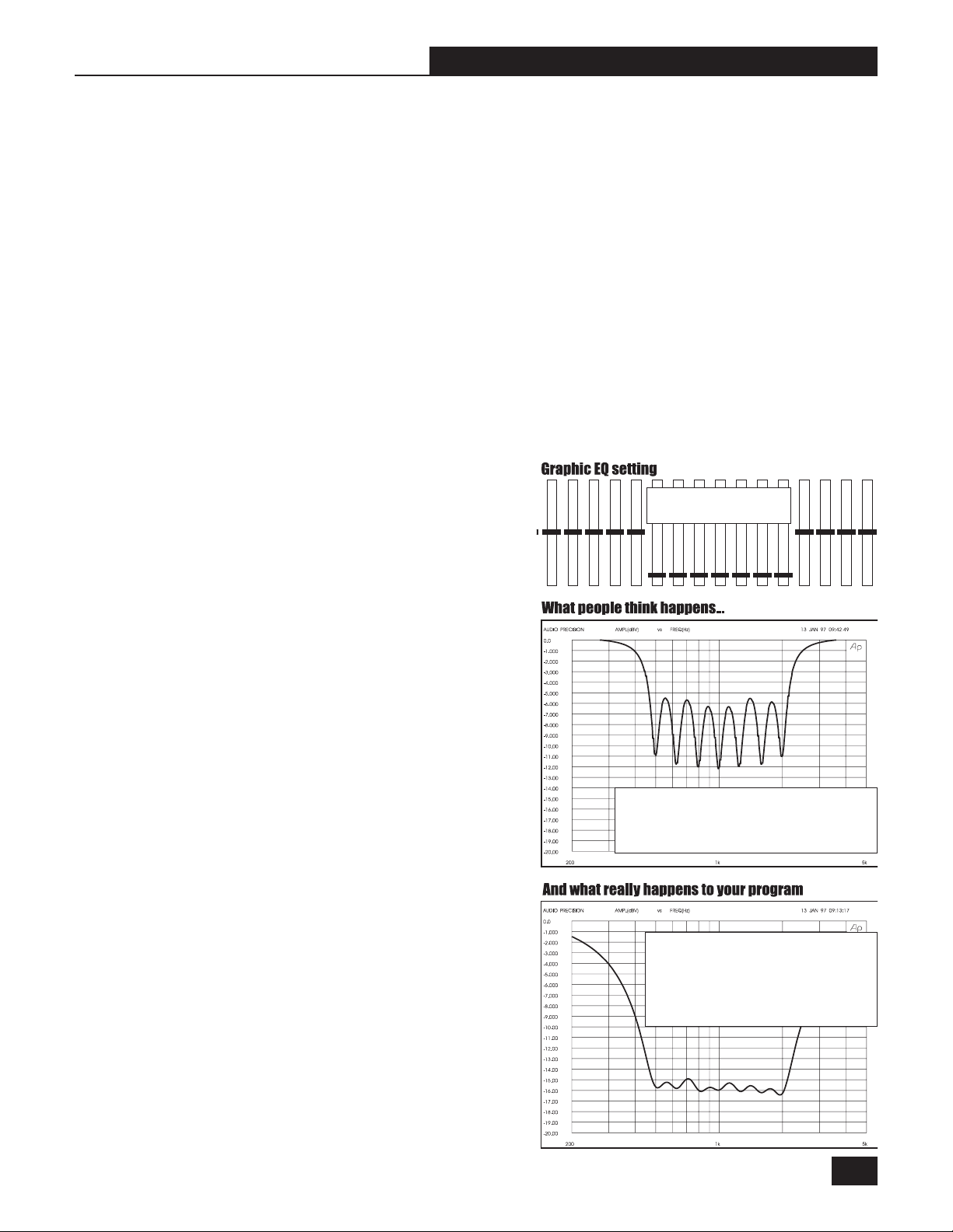
Before the invention of FBX, the most common
device for controlling feedback was the 31-band
graphic EQ. However, FBX has three distinct
advantages. The most obvious is that FBX functions automatically, even during the program.
Another is that FBX micro-filters are precisely
placed anywhere feedback occurs, while EQ
filters are limited to 31 fixed centerpoints. The
difference: FBX filters do not have to be as deep,
so there is more system gain. But the most
important advantage is that FBX micro-filters are
ten times narrower than 31-band EQ filters.
Using FBX micro-filters will return up to 90
percent of the power removed by EQ filters.
-10 dB cut at 500, 630,
1K, 1.25K, 1.6K &2K Hz
If the graphic EQ really had 1/3 octave filter
widths, the frequency response curve would
vary 6 dB between sliders. This would ruin
the sound.
An EQ would need more than 10,000 sliders to
be equivalent to your FBX. With FBX technology,
your microphone will finally sound loud enough,
everyone in the audience will understand each
word, and feedback will be far less likely to make
an unwelcome and unexpected visit.
Figure 6a - Graphic-EQ effect on program
Graphic EQs usually use one-octavewide overlapping filters that provide
much smoother frequency response
curves. Notice that the overlapping filters add together to cut -16 dB when
the sliders are only pulled down -10 dB.
B1-SWM-Op-Guide-v4.pmd 030108-hto
19
Page 20

Section SIX : FBX Feedback Exterminator
6.2 Two FBX Advantages
There are two reasons why the True Mobility
TM
system from Sabine is able to eliminate
feedback while maintaining a high quality
audio signal.
You get back this
much sound & power
with the FBX!
6.2.1 Advantage #1
First, an FBX filter represents a direct hit
on feedback! The FBX targets feedback
without taking a big chunk out of your sound.
1/3-octave
EQ filter
Tests prove that a single 1/3-octave EQ
slider pulled down 12 dB removes almost
half the power going to the speakers over a
two-octave range. Furthermore, you can’t
place a graphic EQ filter precisely on the
ringing frequency. If you pull down multiple
Figure 6b - FBX Filters a Direct Hit on Feedback
sliders in a normal setup, you end up with giant frequency holes in your music (see Figure 6b). On the
other hand, FBX micro-filters are 10 times narrower—you get back up to 90% of the power you lose with
a graphic EQ! That means more gain before feedback and no loss in sound quality.
EXAMPLE: In Figure 6c, a PA system was set up using a microphone,
mixer, FBX Feedback Exterminator®, power amp and two speakers.
The system’s gain was raised until
the FBX removed nine feedback
points. Next, the FBX was replaced
with a graphic EQ. The EQ was
adjusted while the system gain was
raised to the same level achieved
with the FBX. The frequency response curves of each device were
then plotted.
Figure 6c - FBX Filters vs Graphic EQ Filters
Note how much more of the program
is eliminated using an EQ—whereas only feedback is eliminated using FBX filters.
Direct Hit on Feedback!
FBX filter
Feedback
The grey area
shows you how
much of your
program you
would lose using a
1/3-octave filter to
control feedback
20
6.2.2. Advantage #2
The second reason True Mobility
TM
systems are able to remove feedback while maintaining high quality
audio signal is due to the placement of the signal processing in the input chain of the microphone signal.
Many times signal processing (compression and equalization) is placed after the output stage of a
mixer, meaning it is applied to a combination of inputs mixed together into one output and passed through
the processor. Particularly in the case of equalization and feedback control, one consequence of such
a signal path is that filtering applicable to just one microphone is applied to others in the same mix bus.
In other words, unnecessary filtering (albeit very narrow filtering in the case of an FBX filter) may be
applied to microphones that have different feedback frequencies than some of the filters set.
Placing the filtering and other signal processing in the input signal path is a concept called Targeted
Input Processing. It means each microphone so equipped will have customized, unique signal
processing applied—and no unneeded processing.
Sabine True Mobility Wireless Systems give you
- Targeted processing for each microphone
- Increased mobility
- Quiet, fast and easy setup of FBX filters (Our Fastest FBX setup mode!)
Page 21

Section Six : FBX Feedback Exterminator
Constant Q vs Proportional Q Filters
Constant Q Proportional Q
It is common to describe a filter’s quality factor, or “Q,” as the center frequency of the filter divided by the filter width (in Hertz)
measured at the -3dB point. Filters that have the same Q, or width, at the -3dB point regardless of the filter’s cut or boost are called
Constant Q filters (see p.14, Figure 6a). Filters that get wider as the filter gets deeper are called Proportional Q filters (see p.14,
Figure 6b). Lately, however, the definition of Constant Q is becoming less distinct. Many equalizer manufacturers claim their
equalizers have Constant Q filters, when in fact they get substantially wider as they get deeper. The only way to know for sure
if the filters are truly Constant Q is to inspect their frequency response curves. Sabine FBX Filters are true Constant Q filters.
6.3 Who Needs The FBX?
Virtually every sound system will be improved with the Sabine True Mobility
speakers who do not have sound technicians can now increase their monitor or house system volume so they
can hear themselves clearly and with full fidelity, without worrying if their microphone will suddenly squeal if they
move to the wrong place.
Auditoriums and churches of all sizes will enjoy reliable feedback control. Hotels and conference centers around
the world can offer meeting rooms with microphones that won’t howl during programs. The Sabine True Mobility
Wireless System can be installed in theaters, schools, sports arenas, courtrooms, teleconferencing, intercoms
or interactive remote classrooms—anywhere one or multiple microphones are used.
TM
Wireless System. Singers and
TM
6.4 FBX Setup & Ready Mode
The FBX Section has two modes: Setup and Ready. In Setup, the FBX filters automatically zero in on the
most predominant feedback. Because this is a wireless system, you need to move the microphone to several
areas of use during setup—this will provide maximum gain before feedback before the performance begins.
In Ready mode you are ready for the performance. Use the True Mobility as you would any wireless micro-
phone system. The FBX section will work automatically to kill any additional feedback that happens to arise.
6.4.1 FBX Fixed & Dynamic filters
Here’s how it’s done. FBX filters come in two flavors, fixed and dynamic. Both operate automatically.
Fixed FBX filters: these filters will not change frequency or depth once they are placed during Setup and the
receiver indicates Ready mode. These filters will eliminate the “first-to-feedback” frequencies encountered
during normal system operation.
Dynamic FBX filters: these filters automatically set just like Fixed filters, except they can change frequency
and depth as the need arises. Dynamic Filters stand guard if frequencies not attenuated during Setup begin
to feedback during performance.
If all filters, both Dynamic and Fixed, are in place and new feedback occurs, the Dynamic filters will move to
eliminate the new feedback. You never run out of filters!
B1-SWM-Op-Guide-v4.pmd 030108-hto
21
Page 22
Section Six : FBX Feedback Exterminator
6.4.2 Default FBX filter settings
The Sabine True Mobility
TM
Wireless System provides a total of ten filters for feedback control. The
default setting makes seven of these Fixed and three Dynamic. This can be changed to eight Fixed and
two Dynamic by changing an internal DIP switch position (see Appendix 11.1 FBX Configuration DIP
Switch).
6.4.3 FBX filter width
A default setting of .10 octave has been calculated to eliminate feedback without affecting music
program. If, with all filters properly set, feedback is still occurs, the FBX filters may be set to .20-octave
width. This wider filter setting will help to eliminate feedback trouble areas, but may also affect music
program slightly. The wider setting is generally considered to be appropriate where speech is the primary
usage of the Sabine Wireless. This is to say it will not audibly affect desired program, only feedback.
If the Sabine Wireless is used for music program, we recommend using the default setting of .10 octave
be used. You can change FBX filter width by repositioning an internal DIP switch (see Appendix 11.1
FBX Configuration DIP Switch).
6.5 How To Set Up The FBX Section Of Your True MobilityTM System
Follow these steps to obtain the maximum gain and protection from feedback.
1. Place the speakers in the positions where they will be used during the program.
2. If there is any equipment with a noise gate in the signal path, you MUST DISENGAGE the noise
gate(s) prior to the setup procedure. You may reengage these noise gates upon conclusion of your
FBX setup.
3. Patch your Sabine receiver into the mixer or amp channel. Set the amp master output gain to a
normal operating position.
NOTE: The level of your power amplifier should be set to a
level that allows a healthy gain structure prior to the ampli-
fier. If your amplifier is turned up fully, and your mixer meters
show little movement when signal passes through, you will
improve the performance of your sound system and lower
system noise by reducing the gain on your power amp and
increasing your mixer gain.
Figure 6d - Receiver Output Level
Output Level
4. Turn on your wireless transmitter or
handheld microphone, then the wireless receiver, then the mixer, then any
other accessories, and finally the
power amp. If you are using a graphic
EQ, adjust only for the desired tonal
qualities, but DO NOT NOTCH FOR
FEEDBACK.
Figure 6e - FBX Setup Button
Setup Button
CAUTION: Do not use Sabine wireless receiver for
performance while in Setup mode!
22
Page 23
Section Six : FBX Feedback Exterminator
5. Now you are ready to set FBX filters. Press and hold Setup (far left button) on the wireless receiver,
until the LEDs flash four times, then release it (the Setup LED will come on). This will clear any
FBX filters already in place. You should do this each time you move your sound system,
change a sound system component, or relocate your microphone. Your Sabine True Mobility
Wireless System will remember its settings from the last time you turned the unit off.
6. When the Setup light comes on, your receiver is ready to set FBX filters. With the microphone
turned on, raise the Output Level of the receiver slowly until a strong input signal at the mixer is
apparent (for starters, try the 12:00 position). The microphone should now be audible.
7. During Setup mode, do not talk into the microphone or pass audio program through a transmitter.
This may cause the Sabine True Mobility™ system to set inappropriate filters. The only appropri-
ate use of the setup mode is to create and filter feedback.
8. Slowly raise the mixer channel gain to the point of feedback—and then slowly beyond until you
hear the chirping tones of feedback quickly being eliminated by FBX filters setting. Stop raising gain
after 2 or 3 feedback tones have chirped and corresponding FBX filters have set. Rest assured that
any feedback that occurs will be at a quiet volume, and very short in duration.
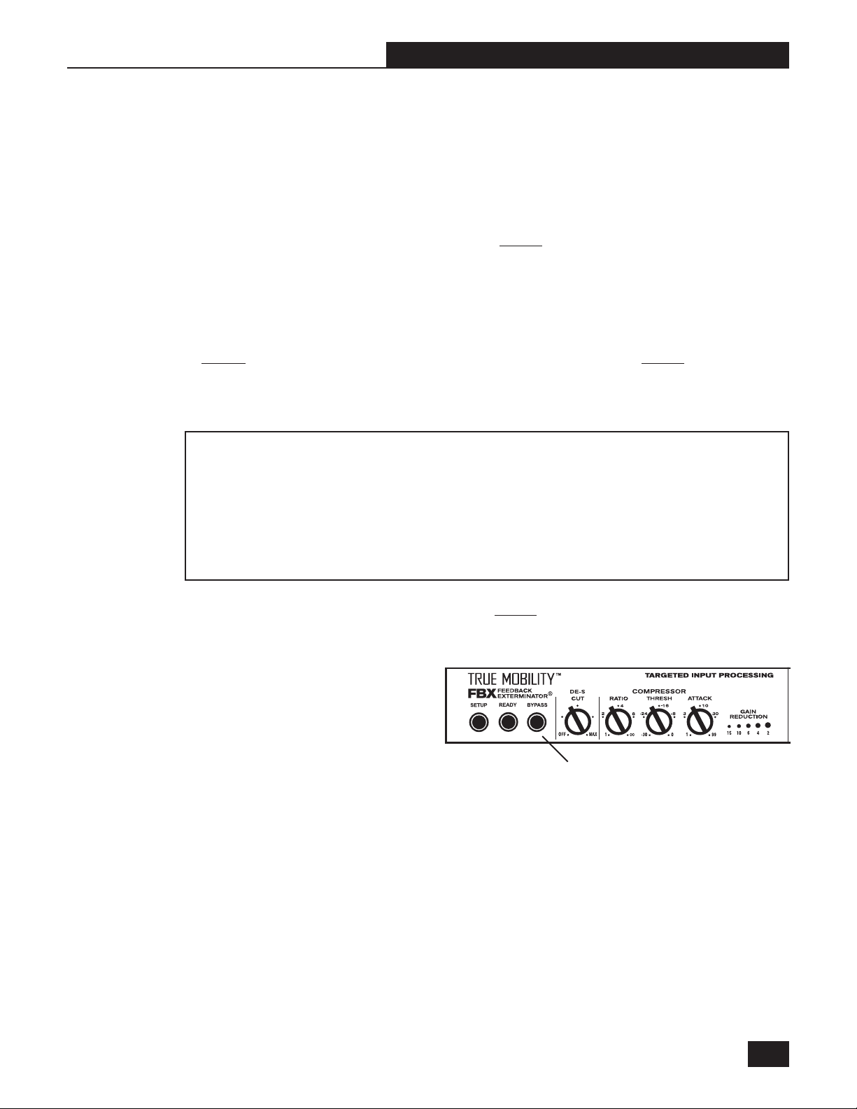
You may quit Setup mode at any time prior to its automatic exit by simply pressing the Ready
button. This will lock all fixed FBX filters, including those not set at the time of your manual
exit—in other words, only the filters set at the time you pushed Ready will be engaged. Dynamic
FBX filters will still work in the event of feedback during performance.
TM
If you quit Setup prior to the FBX Section’s automatic exit (i.e.., after all fixed FBX filters are set),
and later decide you need more gain before feedback (i.e., more fixed filters), you must begin the
Setup process again. See Step 5 above.
9. Move the microphone to another area of use and slowly raise gain until FBX eliminates a few more
feedback tones (2 or 3). Repeat this step until the Setup indicator automatically goes off and the
Ready indicator comes on.
Any feedback that occurs after setup
will be eliminated by Dynamic filters. In
most instances you will experience an
additional gain of 6-9 dB before feedback when using the Sabine True
MobilityTM System. Precise results will
depend on system and acoustical con-
Figure 6f - FBX Section Bypass Button
Bypass Button
siderations.
All fixed filters in place will remain set until the Setup button is pushed and held as described in step
5. All dynamic filters will remain in place until new feedback occurs (wherein they will move to the new
frequency), or until the Setup button is pushed and held.
6.6 Bypass Button
The Bypass button bypasses only the FBX Section, and not the additional signal processing (deessing and compression) available in the Targeted Input Processing section of the Sabine True Mobility
Wireless Receiver.
TM
B1-SWM-Op-Guide-v4.pmd 030108-hto
23
Page 24
Section Seven : De-Esser Set Up
SECTION SEVEN : DE-ESSER SET UP
7.1 The Essence of De-essing
Certain consonant sounds produced by
the human voice have the potential to
overload a microphone capsule, and to
end up as disproportionately harsh and
loud when amplified through a sound
system, and/or recorded to analog or
digital storage media. The most common and obvious of these sounds is the “ssss” sound, associated with pronunciation of both “s” and soft
“c” consonants in many languages, and also the consonants “t,” “f,” and sometimes “d.” The technical
term for this particular vocal sound is “sibilance,” and the devices which control such sounds are typically
called “de-essers” (or sometimes sibilance controllers). The frequency range of sibilance will vary
depending on the singer/speaker, the consonant involved, the orientation to the microphone, the
microphone itself, and the normal variations in human vocalization. The range of frequencies affected
by sibilance starts above 2.5 KHz, and generally tapers off above 10 KHz.
7.1.1 The True Mobility De-esser
The Sabine De-Esser is a type of compressor that operates at frequencies between 2.5 KHz and 12 KHz.
The De-Esser reduces the amplitude of vocal sibilant sounds which may become apparent when a singer
or speaker gets too close to the microphone. When the energy level of high-frequency sounds exceeds
a preset threshold, the de-esser reduces the high frequency response for the length of time the threshold
is exceeded. High frequency energy below the threshold will not be affected by the de-esser. Low energy
level, high frequency sounds also are not affected.
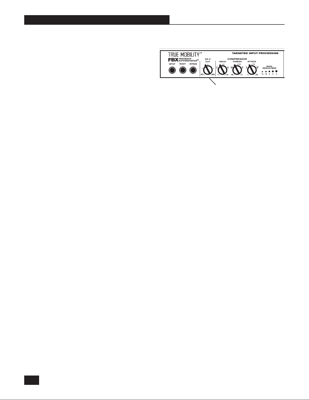
De-esser Control Knob
Figure 7a - De-esser Control Knob
7.2 Using the De-esser
The Sabine De-Esser is simple to use. The fully counterclockwise position is OFF. From that point,
the more you turn the knob clockwise, the more sibilance is reduced from your program.
Sabine De-Esser can be used to compensate for varying sibilance levels due to placement of lavalier
microphones (the closer the lavalier microphone is to the user’s mouth, the greater is the potential for
audible sibilance).
24
Page 25
Section Eight : Compressor Set Up
SECTION EIGHT : COMPRESSOR SET UP
8.1 Basics of Compression
The dynamic range (how loud we can hear to how quiet a sound we can detect) of the human ear is far
greater than the capacity of sound systems to reproduce. Although some of this equipment limitation is
at the upper extreme of the dynamic range (where too loud a signal will produce distortion), much of the
restriction occurs at the low level end, where the signal disappears below the “noise floor” of the circuitry.
A compressor (or in its most powerful form, a limiter) is the most widely used tool for controlling dynamic
range. In the simplest terms, a compressor is designed to squeeze the dynamic range of an audio
program; i.e., to make quiet signals louder, and loud signals quieter. A compressor becomes a limiter
when the compression ratio (the ratio of the input gain change to the output gain change) is so high that
the output level won’t rise above a “brick wall” ceiling regardless of how loud the input gets (typically 10:1
and greater).
A compressor acts like an “automatic mix engineer” with a hand on the fader and an inhumanly fast
reaction time. When the input level increases, the engineer drops the fader; when the level decreases,
the fader is raised. When the amount of fader compensation equals the variation in signal level, the
output level of the audio program will sound consistent.
The practical benefits of compression and limiting include:
1. Speaker protection. A compressor will control sudden level peaks and prevent your speakers from
damage.
2. Perceived increase in loudness. Because peak levels are kept from rising as high as uncompressed
signals, you gain headroom for your audio program and can raise its overall average gain. Compression is often added to the entire audio mix, both in live sound and recording, to increase its perceived
loudness.
3. Consistent Level. For expressive instruments or vocals, which may have a large dynamic range,
compression can help maintain consistent mix levels. So a speaker who varies from a whisper to a
shout will not disappear or stand out in the mix, relative to other less dynamic instruments.
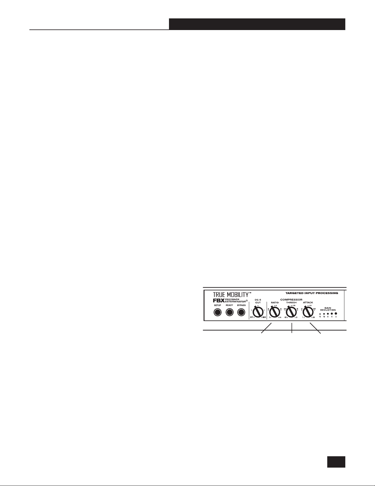
8.2 Using the Compressor
Compressor controls are located immediately
to the right of the FBX and De-esser panels. The
controls consist of standard Ratio, Thresh
(threshold), and Attack knobs, and a horizontal
LED ladder showing compressor gain reduction.
Ratio
Control
Knob
Ratio: Compression ratio is the ratio of
the input gain change to the out-
Figure 8a - Compressor Section
put gain change. The compression ratio on your Sabine Wireless ranges from 1:1 to infinity:1 (limiting).
Thresh: Compression threshold is the level at which the compressor/limiter begins to act on the
signal. The input level threshold at which compression is engaged can be adjusted from
-30 dBV to 0 dBV.
Attack: Compressor attack time is the time it takes to compress after a strong signal reaches the
threshold level.
NOTE 1 : Use the mixer channel or amp gain for gain make-up after compression.
NOTE 2 : Default Release Time for the True Mobility Compressor is 400 mSec with the Knee set to
Soft.
B2-SWM-Op-Guide-v4.pmd 030108-hto
Threshold
Control
Knob
Attack
Control
Knob
25
Page 26

Section Eight : Compressor Set Up
8.3 Suggested Compressor Settings
8.3.1 Vocal Compression
The renowned expressiveness of the human voice
is due in large part to its dynamics. A vocal that
varies from a whisper to a scream has a strong
emotional impact, but those same dynamics
present a challenge to the sound engineer. Ideal
vocal compression maintains some dynamic range
while keeping the vocal the focal point of the mix.
Ratio: A soft voice might require a ratio of 2:1,
whereas a loud voice might require a ratio setting
of 6:1.
Thresh: The higher the threshold setting, the
more signal required to initiate compression.
Attack: Short attack.
8.3.2 Guitar Compression
A high compression (with gain makeup) will add
sustain to held notes and chords. Moving the
threshold will change the audible thick/thinness of
the guitar tone, but generally you want to compress all the notes played. Be wary of too quick
an attack, which may reduce the percussive
attack of the guitar notes. In general, use a longer
attack for instruments. Be wary of too high a
compression ratio, which may make a noisy
guitar amplifier more objectionable.
Figure 8b
(Ratio set to from 2 to 6:1; threshold set so vocal peaks
are compressed about 4-6 dB, attack should be fairly
quick).
Figure 8c
(Ratio set from 6 to 20:1, threshold variable, slower
attack.)
8.3.2 Additional Settings
For your own recall, draw in any settings and
their use that you have discovered.
26
Page 27

Section Nine : Compressor Setup
8.4 Possible Compression Trouble Areas
Like any signal processing, compression can be misused, and cause undesirable problems in the
audio signal. Some of these problems include:
1. Noise. If the threshold for compression is set too low, and the output gain is raised substantially to
make up for the gain loss of compression, the resulting output signal can be noisy. This is because
the input signal must be raised significantly to produce the same output level, and the noise floor of
your equipment will be amplified unnecessarily. This problem will be exaggerated if the input signal
level to the compressor is very low (which will already degrade the signal-to-noise ratio).
2. Breathing. In situations where the compression ratio is high, the threshold is low, and the release
time of the compressor is short, the noise floor will modulate up and down as the audio signal stops
and starts.
3. Over-compression. Applying too much compression to a mix can sometimes result in such
evened-out dynamics that the “life” of the music has been removed or curtailed. Dynamic variation
in music is a major component of its excitement and interest; don’t remove them, just control them.
This may be particularly true for percussive sounds such as drums.
B2-SWM-Op-Guide-v4.pmd 030108-hto
27
Page 28

Section Nine : Tips and Troubleshooting
SECTION NINE : TIPS AND TROUBLESHOOTING
9.1 Tips for Maximum Performance of your True Mobility Wireless System
· Keep a clear and unobstructed path between transmitter and receiver.
· Position receiver antennas at least one meter off the performance floor level.
· Avoid placing receiver antennas near large metallic or other dense materials.
· Keep receiver antennas away from RF signal generating equipment (computers, high-voltage equip-
ment, etc.).
· If the receiver is rack mounted, you can use the Sabine SWA100 Rear to Front Antenna Converter
Kit or one of the Extension Antenna kits ( UHF systems: SWAUEXT; VHF systems: SWAVEXT)
to improve RF performance.
· Position antennas perpendicular to each other.
· Use a Sabine Antenna Divider System (SWA4U, SWA4V) for multiple system installation.
NOTE: It is highly recommended that SWAUB Antenna Boosters be used with the Antenna Divider System. The Antenna Boosters will boost the signal +13dB. Placement of the Divider more
than 10 meters from the receiver positively requires the use of Antenna Boosters.
· Keep two extra Sabine Rechargeable 9-volt NiMH batteries charging in the on-board, dual battery
charger.
9.2 Troubleshooting
Problem: True Mobility receiver and transmitter power are on, receiver RF Signal LEDs and
Input Level LEDs are lighting up, but no sound from system.
Solution: Check connection between receiver and mixer/amp. Adjust receiver Output Level
control.
Problem: True Mobility receiver and transmitter power are on, but receiver RF Signal LEDs
and Input Level LEDs are not lighting up.
Solution: Check transmitter On/Battery Indicator. Replace weak battery with fresh battery
from charger unit if necessary. Check transmitter and receiver frequency Group/
Channel settings (make sure they match). Check receiver squelch setting. Check
receiver antenna connections. Check distance between transmitter and receiver
antennas and possible obstructions in path.
Problem: Transmitter is on, but sound is noisy.
Solution: Check transmitter On/Battery Indicator. Replace weak battery with fresh battery
from charger unit if necessary. Check for other sources of RF interference (high
voltage equipment, lighting equipment, etc.). If using multiple units, make sure that
all units are set to different frequencies within their allotted group. Do not mix groups
unless so stated in Section Ten. Check distance between transmitters and receiver
antennas.
28
Problem: Transmitter is off, but noise still coming from receiver.
Solution: Adjust receiver squelch control. Check for other sources of RF interference (high
voltage equipment, lighting equipment, trolley cars, etc.). Select another frequency.
Check connection and position of the receiver antennas. Utilize a Sabine Extension
Antenna and/or Extension Antenna Booster (Extension Antenna Booster requires
the use of a Sabine Antenna Divider).
Page 29

SECTION TEN : Multiple Frequency & Use Charts
SECTION TEN : MULTIPLE FREQUENCY & USE CHARTS
10.1 UHF Frequency Code U3 [USA]
SWM-3000 UHF transmitters and receivers have both Group and Channel selector knobs. The channels
within each group have been arranged so that you can use up to 14 wireless units at a single location
without having the units interfere with each other.
In general, use channels from within the same group to avoid interference. For maximum
number of units, see Example #2 below.
EXAMPLE: The 8 channels within group 1 are all compatible. To use 8 UHF units at a single location,
set the receivers and transmitters as follows:
Transmitter/Receiver GROUP CHANNEL
unit #1 1 1
unit #2 1 2
unit #3 1 3
unit #4 1 4
unit #5 1 5
unit #6 1 6
unit #7 1 7
unit #8 1 8
EXAMPLE: To use the maximum number of 14 units together, use all 7 channels of GROUP 3,
plus all 7 channels of GROUP 4.
NOTE : To avoid intermodulation distortion (IMD) interference, all transmitters must be kept at
least 5 meters from any True Mobility UHF receiver antenna.
Frequencies in USA 900 MHz UHF Systems
CHANNEL (MHZ)
12 3 45 6 78
1 914.275 914.900 916.375 916.725 920.200 921.200 926.800 929.875 3m
2 915.150 916.125 917.925 922.650 924.075 924.775 928.125 928.500
3 914.250 915.475 918.275 919.450 925.575 926.650 929.150 5m
GROUP
4 915.075 917.875 919.050 925.225 926.300 928.750 929.925
Minimum
distance to
receiver
Guide to new/old Frequency Code designations
UU
U
UU
U1 = U794A (786.275 - 801.925) U3 = U922A (904.275 - 928.5)
HH
H
HH
U2 = U808C (802.675 - 815.95)
FF
F
FF
VV
V
VV
V1 = VND1 (200.35 - 202.6) V3 = VPD2 (202.25 - 204.5) V5 = VPH5 (247.05 - 249.3)
HH
H
HH
V2 = VND2 (201.75 - 204.0) V4 = VPE4 (215.2 - 217.45) V6 = VPH4 (245.8 - 248.05)
FF
F
FF
B2-SWM-Op-Guide-v4.pmd 030108-hto
29
Page 30

Section Ten : Multiple Frequency & Use Charts
10.2 UHF Frequency Code U2 [Export]
SWM-3000 UHF transmitters and receivers have both Group and Channel selector knobs. The channels within each
group have been arranged so that you can use up to 10 wireless units at a single location without having the units
interfere with each other.
In general, use channels from within the same group to avoid interference (Group 6 is an exception,
see NOTE 2 below). For the maximum number of units, refer to EXAMPLE #2 below.
EXAMPLE 1: The 6 channels within Group 1 are all compatible with each other. To use six UHF units at a single
location, set the receiver and transmitter as follows:
Transmitter/Receiver GROUP CHANNEL
unit #1 1 1
unit #2 1 2
unit #3 1 3
unit #4 1 4
unit #5 1 5
unit #6 1 6
EXAMPLE 2: To use the maximum number of 10 units together, use all six channels of U2 Group 4, plus
the following 4 additional channels from U2 Groups 1-5 :
Transmitter/Receiver GROUP CHANNEL
unit #7 1 5
unit #8 3 1
unit #9 5 1
unit #10 6 3
NOTE 1: To avoid intermodulation distortion (IMD) interference, all transmitters must be kept at least 6
meters from any True Mobility UHF receiver antenna.
NOTE 2: The three channels in U2 Group 6 are not compatible with each other and may cause interfer-
ence. Do not use these frequencies together as a group.
UHF Frequency Code U2: 802.675 - 815.950 MHz
CHANNEL (MHZ)
123456
1 802.675 804.250 806.175 808.450 811.075 814.675 5m
2 802.325 803.900 805.825 808.100 810.725 814.325
3 801.000 802.875 805.175 807.900 811.050 815.600 3m
GROUP
4 800.600 802.475 804.775 807.500 810.650 815.200
5 803.250 809.250 813.250 1m
6 800.250 808.450 815.950
Minimum
distance to
receiver
10.3 UHF Frequency Code U1 [Export]
SWM-3000 UHF transmitters and receivers have both Group and Channel selector knobs. The channels within
each group have been arranged so that you can use up to 10 wireless units at a single location without having the
units interfere with each other.
In general, use channels from within the same group to avoid interference. For maximum number of
units, see Example #2 on page 29.
30
Page 31

Section Ten : Multiple Frequency & Use Charts
EXAMPLE 1: The 8 channels within group 1 are all compatible with each other. To use 8 UHF units at a single
location, set the receivers and transmitters as follows:
Transmitter/Receiver GROUP CHANNEL
unit #1 1 1
unit #2 1 2
unit #3 1 3
unit #4 1 4
unit #5 1 5
unit #6 1 6
unit #7 1 7
unit #8 1 8
EXAMPLE 2: To use the maximum number of 14 units together, use all 7 channels of Group 3, plus all 7
channels of Group 4.
NOTE : To avoid intermodulation distortion (IMD) interference, all transmitters must be kept at least 5
meters from any True Mobility UHF receiver antenna.
UHF Frequency Code U1: 786.275 - 801.925 MHz
CHANNEL (MHZ)
12345678
1 786.275 786.900 788.375 788.725 792.200 793.200 798.800 801.875 3m
2 787.150 788.125 789.925 794.650 796.075 796.775 800.125 800.500
3 786.250 787.475 790.275 791.450 797.575 798.650 801.150 5m
GROUP
4 787.075 789.875 791.050 797.225 798.300 800.750 801.925
10.4 VHF Frequencies [USA]
The following frequencies are offered for the USA market. Refer to the Frequency Group
Code on your Sabine SWM-1600 VHF receiver.
V1 200.350~202.600 MHz (TV Channel 11 - 198~204MHz)
Ch.1 Ch.2 Ch.3 Ch.4 Ch.5 Ch.6 Ch.7 Ch.8
200.35 200.65 200.95 201.25 200.5 200.8 201.1 201.4
Ch.9 Ch.10 Ch.11 Ch.12 Ch.13 Ch.14 Ch.15 Ch.16
201.7 202 202.3 202.6 201.55 201.85 202.15 202.45
V2 201.750 - 204.000 MHz (TV Channel 11 - 198~204MHz)
Ch.1 Ch.2 Ch.3 Ch.4 Ch.5 Ch.6 Ch.7 Ch.8
201.75 202.05 202.35 202.65 201.9 202.2 202.5 202.8
Ch.9 Ch.10 Ch.11 Ch.12 Ch.13 Ch.14 Ch.15 Ch.16
203.1 203.4 203.7 204 202.95 203.25 203.55 203.85
Minimum
distance to
receiver
NOTE 1: Up to 3 VHF systems can be used simultaneously for each group of 16 frequencies. For use of
up to six systems, use 3 systems from one group and 3 from the other group. For best
results, use consecutive channels starting from channel 1.
NOTE 2: If TV channel 11 is used for broadcast in your area, we do not recommend using the VHF chan-
nels — use UHF instead.
Guide to new/old Frequency Code designations
UU
U
UU
U1 = U794A (786.275 - 801.925) U3 = U922A (904.275 - 928.5)
HH
H
HH
U2 = U808C (802.675 - 815.95)
FF
F
FF
VV
V
VV
V1 = VND1 (200.35 - 202.6) V3 = VPD2 (202.25 - 204.5) V5 = VPH5 (247.05 - 249.3)
HH
H
HH
V2 = VND2 (201.75 - 204.0) V4 = VPE4 (215.2 - 217.45) V6 = VPH4 (245.8 - 248.05)
FF
F
FF
B2-SWM-Op-Guide-v4.pmd 030108-hto
31
Page 32

Section Ten : Multiple Frequency & Use Charts
10.5 VHF Frequencies [Export]
The following frequencies are offered for the export market. NOTE: Frequencies offered are subject to
change. Please consult the back of your VHF receiver for the frequency group number and frequency
chart.
V3 202.250 - 204.500 MHz *
Ch.1 Ch.2 Ch.3 Ch.4 Ch.5 Ch.6 Ch.7 Ch.8
202.25 202.55 202.85 203.15 202.4 202.7 203 203.3
Ch.9 Ch.10 Ch.11 Ch.12 Ch.13 Ch.14 Ch.15 Ch.16
203.6 203.9 204.2 204.5 203.45 203.75 204.05 204.35
V4 215.200 - 217.450 MHz *
Ch.1 Ch.2 Ch.3 Ch.4 Ch.5 Ch.6 Ch.7 Ch.8
215.2 215.5 215.8 216.1 215.35 215.65 215.95 216.25
Ch.9 Ch.10 Ch.11 Ch.12 Ch.13 Ch.14 Ch.15 Ch.16
216.55 216.85 217.15 217.45 216.4 216.7 217 217.3
V6 245.800 - 248.050 MHz *
Ch.1 Ch.2 Ch.3 Ch.4 Ch.5 Ch.6 Ch.7 Ch.8
245.8 246.1 246.4 246.7 245.95 246.25 246.55 246.85
Ch.9 Ch.10 Ch.11 Ch.12 Ch.13 Ch.14 Ch.15 Ch.16
247.15 247.45 247.75 248.05 247 247.3 247.6 247.9
V5 247.050 - 249.300 MHz *
Ch.1 Ch.2 Ch.3 Ch.4 Ch.5 Ch.6 Ch.7 Ch.8
247.05 247.35 247.65 247.95 247.2 247.5 247.8 248.1
Ch.9 Ch.10 Ch.11 Ch.12 Ch.13 Ch.14 Ch.15 Ch.16
248.4 248.7 249 249.3 248.25 248.55 248.85 249.15
* NOTE: Up to 3 VHF systems can be used simultaneously for each group of 16 frequencies.
For use up to six systems, use 3 systems from one group and 3 from another group.
For best results, use consecutive channels starting from channel 1.
Guide to new/old Frequency Code designations
UU
U
UU
U1 = U794A (786.275 - 801.925) U3 = U922A (904.275 - 928.5)
HH
H
HH
U2 = U808C (802.675 - 815.95)
FF
F
FF
VV
V
VV
V1 = VND1 (200.35 - 202.6) V3 = VPD2 (202.25 - 204.5) V5 = VPH5 (247.05 - 249.3)
HH
H
HH
V2 = VND2 (201.75 - 204.0) V4 = VPE4 (215.2 - 217.45) V6 = VPH4 (245.8 - 248.05)
FF
F
FF
32
Page 33
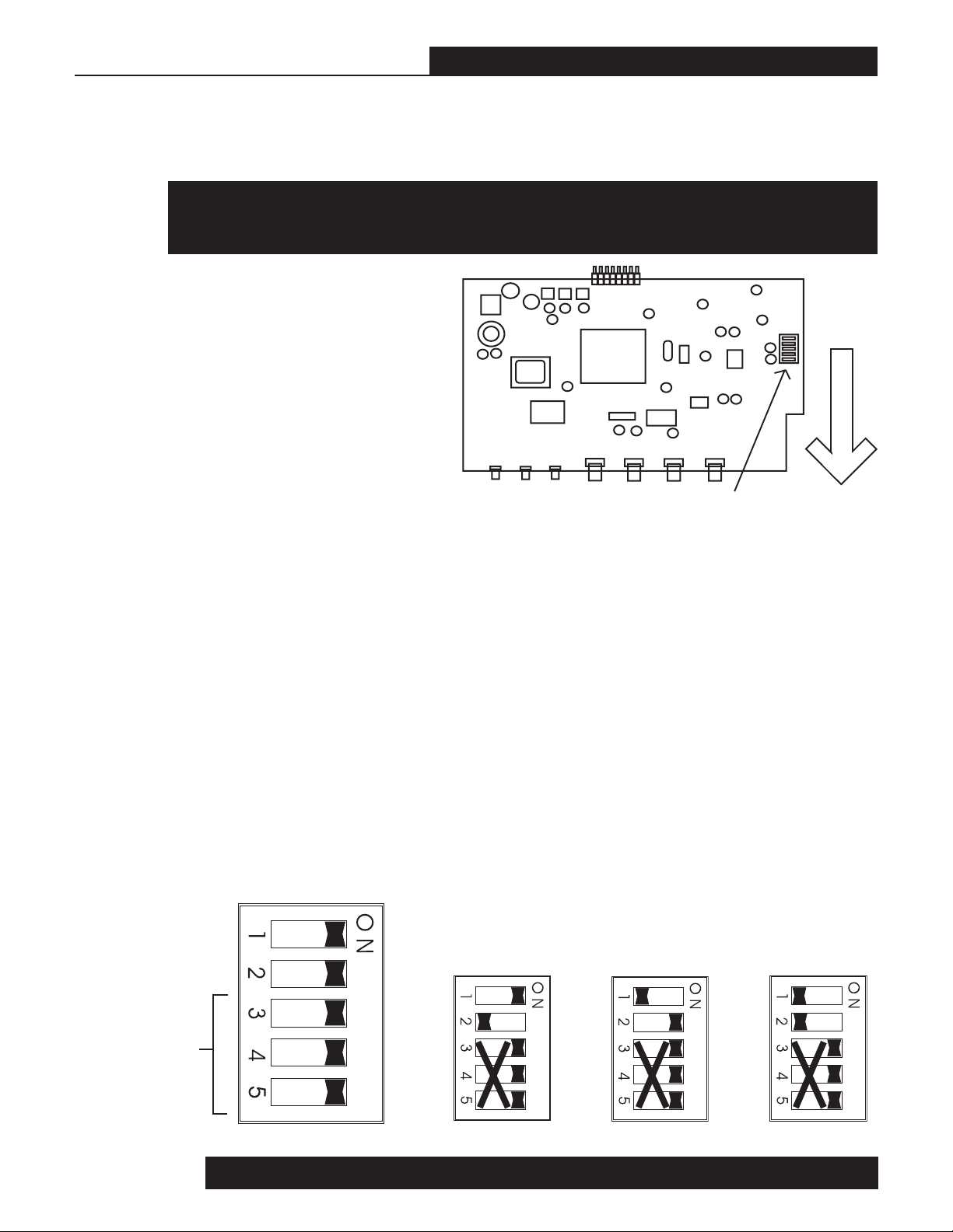
Section Eleven : Appendices
SECTION ELEVEN : APPENDICES
11.1 FBX Configuration DIP Switch
WARNING: ELECTRIC SHOCK HAZARD! UNPLUG receiver BEFORE taking off top cover! Serious injury or death may result if unit is opened/worked on while plugged in. These procedures are to be performed by qualified personnel only.
Refer to Section 6.5 How to Set Up the
FBX Section of Your True Mobility System for a description of Fixed versus Dy-
namic FBX Filters.
1. Remove receiver top cover
Take out four screws on each side and
two from the top of the back panel. Sort
and save all screws. Lift the back of
the top cover, and then pull until the
edge of the top cover (and three tabs)
emerge from under the front panel plastic rim.
Figure 11a - FBX Configuration DIP Switch
2. Change DIP switch settings
There are two PC boards inside the receiver. With the front of the unit facing you, the left and smaller
board (Figure 11a) has a DIP switch in the middle of the right hand side. The DIP switch is covered with
a translucent piece of yellow plastic wrap. Pull off the wrap (it cannot be reused). Note that there are five
switches. One side of the DIP switch is clearly marked ON. The factory default setting is with all switches
set to ON (see Figure 11b).
DIP Switch
Front of box
Refer to Figure 11c to set the number of Fixed and Dynamic filters to 8 Fixed and 2 Dynamic and Figure
11d to widen the filter width to .20 (1/5) octave. These options can be combined to produce 8 Fixed and
2 Dynamic 1/5-octave filters by pushing switch numbers 1 and 2 to the OFF position (Figure 11e). Refer
to Section 6.5 for a complete understanding of these options.
3. Replace top cover
Align and insert the three front tabs under the front panel plastic rim, then lower the back of the cover.
Replace all screws. DO NOT FORCE screws. If they do not go in easily, adjust cover alignment and try
again.
Default setting
7 Fixed, 3 Dynamic
One-tenth Octave
Number of Fixed/
Dynamic filters
FBX filter width
DO NOT
CHANGE
More Fixed filters
8 Fixed, 2 Dynamic,
One-tenth Octave
Wider FBX filters
7 Fixed, 3 Dynamic
One-fifth Octave,
Both
8 Fixed, 2 Dynamic,
One-fifth Octave
Figure 11b
Figure 11c
WARNING: Do not change switch 3, 4 or 5 from the default ON setting!
Figure 11d
Figure 11e
B2-SWM-Op-Guide-v4.pmd 030108-hto
33
Page 34

Section Eleven : Appendices
11.2 Beltpack Transmitter Connector Wiring Diagrams
Two-wire electret condenser microphone capsule
Three-wire electret condenser microphone capsule
Dynamic microphone
Electric guitar
Line-in (impedance 8K ohm ATT. 10 dB)
34
Page 35
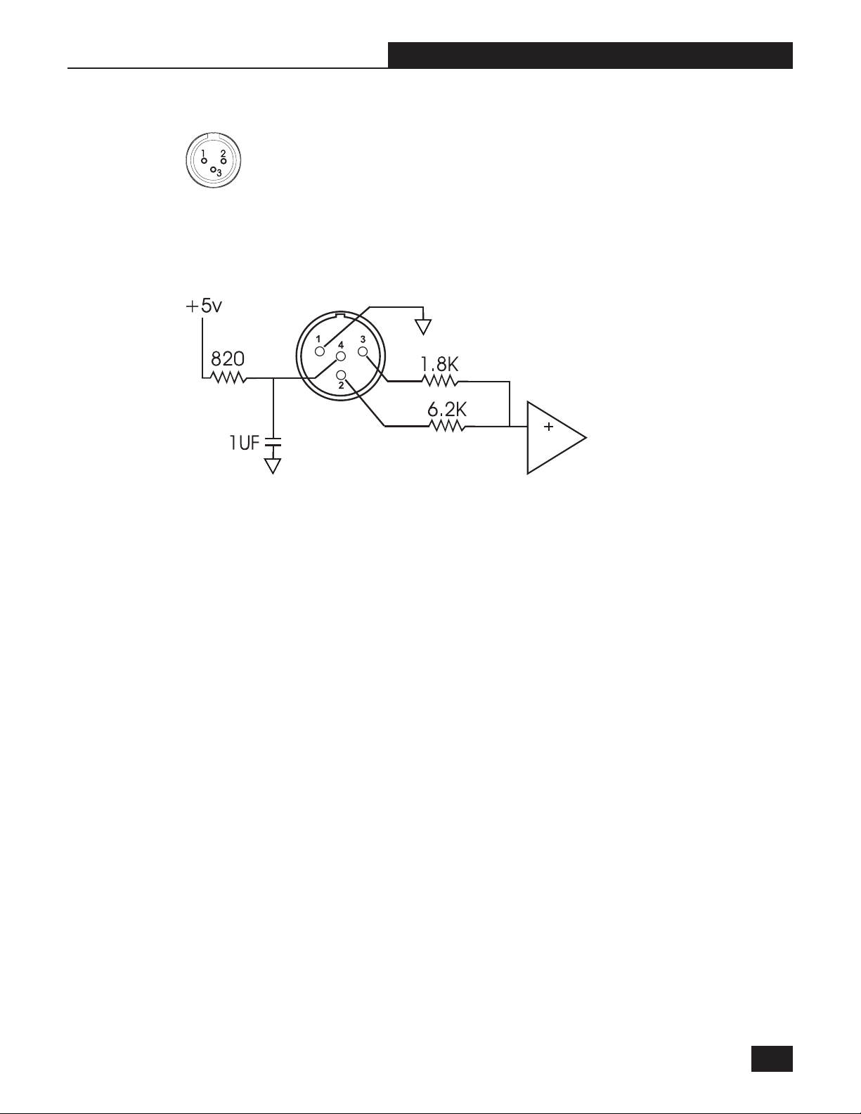
11.3 XLR Connector
1. Shield
2. Positive
3. Negative
11.4 Beltpack Transmitter Schematic
Section Eleven : Appendices
B2-SWM-Op-Guide-v4.pmd 030108-hto
35
Page 36

Section Eleven : Appendices
11.5 Engineering Specifications
SW30-R UHF Receiver
Carrier Frequency Range: UHF Band 794-930 MHz
Frequencies: 30 pre-programmed
Oscillation Mode: PLL synthesized
Receiving Mode: True diversity
Sensitivity: 6 dBV at S/N over 70 dB
Image Rejection: >63 dB
Spurious Rejection: >76 dB
Stability: +/- 0.005%
Maximum Deviation: +/- 40 KHz
Dynamic Range: >100 dB
S/N Ratio: 95 dB (Typical)
THD: <0.3%
Squelch: Sabine two-stage
Squelch Quieting: 6-30 dB
Frequency Response: 50 Hz-18 KHz +/- 3 dB
Output Configuration (mic level):
1/4 inch connector, unbalanced
XLR connector, balanced
Nominal Audio Output Level:1 dBV, with 20 dB headroom
Battery Charger: Built-in dual slot
Antennas: 2, 3/4λ
Power Supply: 12-15 VDC/100-240 VAC 50-60 Hz
Rack-Mountable case, (1U with rack mount ears)
Working Range: 100 meters
1
SW16-R VHF Receiver
Carrier Frequency Range: VHF Band 160-250 MHz
Frequencies: 16 pre-programmed
Oscillation Mode: PLL synthesized
Receiving Mode: True diversity
Stability: +/- 0.005%
Sensitivity: 10 dBV at S/N over 80 dB
Image Rejection: >63 dB
Spurious Rejection: >76 dB
Maximum Deviation: +/- 30 KHz
Dynamic Range: >100 dB
S/N Ratio: >95 dB (Typical)
THD: <0.3%
Squelch: Sabine two-stage
Squelch Quieting: 12-40 dB
Frequency Response: 50 Hz-18 KHz +/- 3 dB
Output Configuration (mic level):
1/4 inch connector, unbalanced
XLR connector, balanced
Nominal Audio Output Level: 0.5 dBV, with 20 dB headroom
Battery Charger: Built-in dual slot
Antennas: 2, 1/4λ
Power Supply: 12-15 VDC/100-240 VAC 50-60 Hz
Rack-Mountable case, 1U (with rack mount ears)
Working Range: 100 meters
1
2
Handheld Microphone
Element: Condenser
Antenna: Built-in
FM Deviation: 30 KHz for VHF, 40 KHz for UHF
RF Frequency Stability: +/- 0.005%
RF Output: 2 mW ERP maximum
Spurious output: < 4 nW
Dimensions: 9.6875 in. x (1.95 in to 1.49 in)
Battery: One 9V (or Sabine Rechargeable)
Battery Life: 500 charge cycles
Lavalier Microphone
Transducer type: Electret condenser
Frequency Response: 50 Hz to 19,000Hz
Directional Characteristic: Uni-Directional
Sensitivity: -46 dB +3 dB at 1KHz ( 0db = 1V/Pa)
Maximum Sound Pressure: 140 dB SPL
Output Impedance: 2KΩ
Equivalent Acoustic Noise: 27 dB SPL A-Weighted
Power Requirements: Regulated nominal +5Vdc (@ 220uA)
source provided at microphone connector pin #4 relative to pin
#1 of a Sabine True Mobility wireless beltpack transmitter.
Weight: 18 g
Dimensions: 11 x 26.8 mm
UHF BeltPack Transmitter
FM Deviation: 40 KHz
RF Frequency Stability: +/- 0.005%
Spurious output: < 4 nW
RF Output: 10 mW ERP maximum
Audio gain: 0-30 dB
Mic input impedance: 470 K Ohms
Mic bias: 5V
Mic connector: 4-pin
Antenna type: 1/4λ, (3.42 in., rigid wire type)
Dimensions: 4.02 in. x 1.24 in x 2.49 in.
Battery: One 9V (or Sabine Rechargeable)
Battery Life: 500 charge cycles
VHF BeltPack Transmitte
FM Deviation: 30 KHz
RF Frequency Stability: +/- 0.005%
Spurious output: < 4 nW
RF Output: 10 mW ERP maximum
Audio gain: 0-30 dB
3
Mic bias: 5V
Mic input impedance: 470 K Ohms
Mic connector: 4-pin
Antenna type: self contained
Dimensions: 4.02 in. x 1.24 in x 2.49 in.
Battery: One 9V (or Sabine Rechargeable)
Battery Life: 500 charge cycles
r
36
Page 37

Section Eleven : Appendices
SWA4U UHF Antenna Divider
Filter Bandwidth: 750~960 MHz +/- 3 dB
3rd Order Interception: (+) 22 dBm
Noise Figure: < 3.7 dB (Center Band)
Input/Output Gain: (+)1.6dB (Center Band)
Output Port Isolation: 32 dB minimum
Connector: TNC type
Power Supply: DC 12~18 V
Current Drain: < 176 mA
SWA4V VHF Antenna Divider
Filter Bandwidth: 165-250 MHz +/- 3 dB
3rd Order Interception: (+) 35.5 dBm
Noise Figure: < 6dB (Center Band)
Input/Output Gain: (+) 1dB (Center Band)
Output Port Isolation: 16 dB minimum
Connector: TNC type
Power Supply: DC 12-18 V
Current Drain: < 148 mA
FBX Filters
Ten independent digital filters per channel,
controlled automatically from 20 Hz to 20 KHz
Filter depth: 3 dB steps from 0 dB to -40 dB
Filter width: .1 or .2 octave
Resolution: 1 Hz from 20 Hz to 20 KHz
Time required to find and eliminate feedback:
typically 0.3 seconds @ 1 KHz
4
Digital Compressor
Threshold: -30 dB to 0 dB
Ratio: 1:1 through infinity
Knee: soft
Attack: 1-99 mSec
Release: 400 mSec
Automatic De-Esser
Cut range: 0 to -30 dB
Mechanical
Dimensions: 1U rack mount, 19 x 1.75 x 9 in. (48.3 x 4.5 x
21.6 cm)
Weight: 5.3 lb. (2.4 kg.)
1
Signal-to-noise ratio is the ratio of the maximum undistorted signal by
specification (26 dBV RMS sinewave) to the noise floor.
2
See page 12, NOTE 1 for Level Switch affect on 1/4 inch unbalanced
output.
3
Nominal Audio Output Level plus headroom equals clip level.
4
Below approximately 200 Hz the feedback filters become slightly
wider to increase the feedback and rumble capture speed at these
low frequencies.
(SPECIFICATIONS SUBJECT TO CHANGE WITHOUT
NOTICE)
One-year limited warranty
Patented
Compliance Statement for European RTTE Directive 1999/5/EC
In accordance with RTTE Directive 1999/5/EC, which took effect on April 8, 2000, for most countries in Europe, Sabine Inc.
hereby certifies the following to apply for all models of the Sabine True Mobility™ Wireless Microphone systems and
components:
1. All systems and components conform to the directives outlined in RTTE Directive 1999/5/EC, and to standards ETS
300 445, ETS 300 422, EN 50081-1, and EN 50082-1, as applicable.
2. As of April 8, 2000, these products have been or will be placed on the market in the following European countries:
Germany, Norway, Spain, Italy, Switzerland, Belgium, Czech Republic, Russia, Greece, Denmark, and Iceland.
3. All Sabine True Mobility™ equipment bears the CE mark. In addition to Sabine’s manufacturer’s statement of conformity, compliance and conformity testing has been performed and certified by Electronic Technology Systems (ETS) of
Germany, DAR registration number BPT-ZE-026/96-00.
4. Because radio frequency allocations have not yet been fully harmonized within the European Union, or across Europe
as a whole, all Sabine True Mobility™ transmitters display a “warning sign” to indicate these products are considered
“Class 2” products under the terms of RTTE Directive 1999/5/EC.
CAUTION - Implanted cardiac pacemakers or AICD devices:
Any source of RF (radio frequency) energy may interfere with
normal functioning of the implanted device. All wireless microphones have Iow-power transmitters (less than 0.05 watts output) that are unlikely to cause difficulty, especially if they are at
least a few inches away. However, since a beltpack transmitter typically is placed against the body, Sabine suggests at-
taching it at the belt, rather than in a shirt pocket where it may be
immediately adjacent to an implanted medical device. Note
also that any medical-device disruption will cease when the RF
transmitting source is turned off. Please contact your physician
or medical-device provider if you have any questions, or experience any problems with the use of this or any other RF equipment.
B2-SWM-Op-Guide-v4.pmd 030108-hto
37
Page 38
Section Twelve: Cautions and Warranties
SECTION TWELVE : CAUTIONS & WARRANTY
Warning! This equipment must be earthed.
Caution! Risk of electric shock. Do not open.
Caution! Shock hazard. Do not remove covers. No user serviceable parts
inside. Refer servicing to qualified service personnel.
Warning! To reduce the risk of fire or electric shock, do not expose this product
to rain or moisture.
Attention! Cet appareil doit être relié à la terre.
Attention! Risque de choc électrique; ne pas ouvrir.
Attention! Risque de choc; ne pas oter les capots. Aucune pièce accessible à
l'intérieur. S'addresser à un technicien qualifié.
Attention! Pour réduire le risque d'incendie ou de choc électrique, ne pas laisser
l'appareil sous la plouie ou à l'humidité.
Achtung! Dieses Gerät muss schutzgeerdet sein.
Achtung! Gefar eines elektrischen Stormschlags. Gehause nicht öffnen.
Achtung! Gefar eines elektrischen Stormschlags. Gehäuse nicht öffnen. Keine
con Benutzer zu bedienenden Teile im Geräteinneren.
Überlassen Sie das Gerät zu Servicezwecken nur geschultem Fachpersonal.
Um Brandgefar oder das Risiko eines elektrischen Schlags auszuschließen,
das Gerät vor Nässe und Feuchtigkeit schützen.
Advertencia! Este equipo debe estar conectado a tierra.
Precaución! Reisgo de descarga eléctrica. No abrir.
Precaución! Riesgo de descarga eléctrica. No desmontar las tapas. Piezas
interiores no reparables por el usuario. Reparable sólo por personal cualificado.
Advertencia! Para reducir el riesgo de incendio o de descarga eléctrica no
exponga este producto a la lluvia o humedad.
FCC Statement:
This device complies with Part 15, Class B, of the FCC Rules. Operation is
subject to the following conditions: (1) This device may not cause harmful
interference; and (2) This device must accept any interference received, including interference that may cause undesired operation.
or modifications to this unit not expressly approved by the party responsible for
compliance could void the user's authority to operate the equipment.
NOTE: This equipment has been tested and found to comply with the limits for a
Class B digital device, pursuant to Part 15 of the FCC Rules. These limits are
designed to provide reasonable protection against harmful interference in a
residential installation. This equipment generates, uses, and can radiate radio
frequency energy and, if not installed and used in accordance with the instructions, may cause harmful interference to radio communications. However,
there is no guarantee that interference will not occur in a particular installation.
If this equipment does cause harmful interference to radio or television reception, which can be determined by turning the equipment off and on, the user is
encouraged to try to correct the interference by one or more of the following
measures:
• Reorient or relocate the receiving antenna.
• Increase the separation between the equipment and receiver.
• Connect the equipment into an outlet on a circuit different from that to
which the receiver is connected.
• Consult the dealer or an experienced radio TV technician for help.
Canadian Compliance Statement
This digital apparatus does not exceed the Class B limits for radio noise emissions from digital apparatus set out in the Radio Interference Regulations of the
Canadian Department of Communications.
Le present appareil numerique n'emet pas de bruits radioelectriques depassant
les limites applicables aux appareils numeriques de la class B prescrites dans
le Reglement sur le brouillage radioelectrique edicte par le ministere des Communications du Canada.
Japanese EMI Compliance Statement
Warning:
Changes
Warning!
The True Mobility is designed to operate from standard AC
power. Please be sure the power in your area is compatible
with the power requirements marked on the rear of the unit.
Using the wrong input voltage may cause permanent damage to
the unit and will void the warranty.
The True Mobility Wireless Microphone system is supplied
with one of the following AC power cords:
Japan 100 VAC
U.S./North America 120 VAC
Continental Europe 230 VAC
United Kingdom 240 VAC
Australia 240 VAC
Battery Caution!
DO NOT BURN OR PUNCTURE BATTERY.
DOING SO COULD RELEASE TOXIC MATERIALS WHICH COULD CAUSE INJURY. DO
NOT SHORT CIRCUIT
1. Read all safety and operating instructions before using this
product.
2. All safety and operating instructions should be retained for
future reference.
3. Obey all cautions in the operating instructions and on the
unit.
4. All operating instructions should be followed.
5. Use only shielded audio and data cables.
6. This product should not be used in the presence of moisture
or rain, or near any water, i.e., a bathtub, sink, swimming pool, wet
basement, etc.
7. This product should be located so that its position does not
interfere with proper ventilation. Do not use in direct
sunlight. Do not place flat against a wall or in a built-in enclosure
that will impede the flow of cooling air.
8. This product should not be placed near a source of heat such as
a stove or radiator.
9. Connect only to a power supply of the type marked on the unit
adjacent to the power entry module.
10.Never break off the ground pin on the power supply cord.
11.Power supply cords should always be handled carefully.
Never walk or place equipment on power supply cords.
Periodically check cords for cuts or signs of stress, especially at
the plug and the point where the cord exits the unit.
12.The power supply cord should be unplugged when the unit
is to be unused for long periods of time.
13.Care should be taken so that objects do not fall and liquids
are not spilled into the unit through the ventilation holes or
any other openings.
14.This unit should be checked by a qualified service technician if:
15.The user should not attempt to service this equipment. All
A. The power supply cord or plug has been damaged.
B. Anything has fallen or been spilled into the unit.
C. The unit does not operate correctly.
D. The unit has been dropped or the enclosure damaged.
service work should be done by a qualified service technician.
MUST BE RECYCLED OR
DISPOSED OF PROPERLY
38
Page 39

Section Twelve : Cautions and Warranties
CAUTION
EXPOSURE TO EXTREMELY HIGH NOISE LEVELS MAY CAUSE A PERMANENT HEARING
LOSS. INDIVIDUALS VARY CONSIDERABLY IN SUSCEPTIBILITY TO NOISE INDUCED
HEARING LOSS, BUT NEARLY EVERYONE WILL LOSE SOME HEARING IF EXPOSED TO
SUFFICIENTLY INTENSE NOISE FOR A SUFFICIENT TIME. THE U.S. GOVERNMENT’S
OCCUPATIONAL SAFETY AND HEALTH ADMINISTRATION (OSHA) HAS SPECIFIED THE
FOLLOWING PERMISSIBLE NOISE LEVEL EXPOSURES:
DURATION/DAY IN HOURS SOUND LEVEL IN dBA, SLOW RESPONSE
ACCORDING TO OSHA, ANY EXPOSURE IN EXCESS OF THE ABOVE PERMISSIBLE LIMITS
COULD RESULT IN HEARING LOSS. EAR PLUGS OR PROTECTORS IN THE EAR CANALS
OR OVER THE EARS MUST BE WORN WHEN OPERATING THIS DEVICE IN ORDER TO
PREVENT A PERMANENT HEARING LOSS, IF EXPOSURE IS IN EXCESS OF THE LIMITS AS
SET FORTH ABOVE. TO ENSURE AGAINST POTENTIALLY DANGEROUS EXPOSURE TO
HIGH SOUND PRESSURE LEVELS, IT IS RECOMMENDED THAT ALL PERSONS EXPOSED
TO EQUIPMENT CAPABLE OF PRODUCING HIGH SOUND PRESSURE LEVELS SUCH AS
THIS DEVICE BE PROTECTED BY HEARING PROTECTORS WHILE THIS UNIT IS IN
OPERATION.
8 90
6 92
4 95
3 97
2 100
1-1/2 102
1 105
1/2 110
1/4 or less 115
Limited Warranty
THIS LIMITED WARRANTY VALID ONLY WHEN PURCHASED AND REGISTERED IN THE
UNITED STATES OR CANADA. ALL EXPORTED PRODUCTS ARE SUBJECT TO
WARRANTY AND SERVICES TO BE SPECIFIED AND PROVIDED BY THE AUTHORIZED
DISTRIBUTOR FOR EACH COUNTRY.
Ces clauses de garantie ne sont vaiables qu’aux Etats-Unis et au Canada. Dans tous les
autres pays, les clauses de garantie et de maintenance sont fixees par le distributeur national
et assuree par lui selon la legislation en vigueur.
Diese Garantie ist nur in den USA and Kanada gultig. Alle Export-Produkte sind der Garantie
und dem Service des Importeurs des jewelligen Landes untervorfen.
Esta garantia es valida solamente cuando el producto es comprado en E.U. continentales o en
Canada. Todos los productos que sean comprados en el extranjero, estan sujetos a las
garantias y servicio que cada distribuidor autorizado determine y otrezca en los diferentes
paises.
ONE-YEAR LIMITED WARRANTY/REMEDY
SABINE, INC. (“SABINE”) warrants this product to be free from defects in material and
workmanship for a period of one (1) year from date of purchase PROVIDED, however, that this
limited warranty is extended only to the original retail purchaser and is subject to the
conditions, exclusions and limitations hereinafter set forth:
CONDITIONS, EXCLUSIONS AND LIMITATIONS OF LIMITED WARRANTIES
These limited warranties shall be void and of no effect if:
a. The first purchase of the product is for the purpose of resale; or
b. The original retail purchase is not made from an AUTHORIZED SABINE DEALER; or
c. The product has been damaged by accident or unreasonable use, neglect, improper service
or maintenance, or other causes not arising out of defects in material or workmanship; or
d. The serial number affixed to the product is altered, defaced or removed; or
e. The power supply grounding pin is removed or otherwise defeated. In the event of a defect
in material and/or workmanship covered by this limited warranty, Sabine will repair the defect in
material or workmanship or replace the product, at Sabine’s option; and provided, however,
that, in any case, all costs of shipping, if necessary, are paid by you, the purchaser.
THE WARRANTY REGISTRATION CARD SHOULD BE ACCURATELY COMPLETED,
MAILED TO AND RECEIVED BY SABINE WITHIN FOURTEEN (14) DAYS FROM THE DATE
OF YOUR PURCHASE.
In order to obtain service under these warranties, you must:
a. Bring the defective item to any Authorized SABINE DEALER and present therewith the
ORIGINAL PROOF OF PURCHASE supplied to you by the AUTHORIZED SABINE DEALER in
connection with your purchase from him of this product. If the DEALER is unable to provide the
necessary warranty service, you will be directed to the nearest other SABINE AUTHORIZED
DEALER which can provide such service.
OR
b. Ship the defective item, prepaid, to:
SABINE, INC.
13301 HIGHWAY 441
ALACHUA, FL 32615-8544
including therewith a complete, detailed description of the problem, together with a legible copy
of the original PROOF OF PURCHASE and a complete return address. Upon Sabine’s receipt
of these items:
If the defect is remedial under the limited warranties and the other terms and conditions
expressed have been complied with, Sabine will provide the necessary warranty service to
repair or replace the product and will return it, FREIGHT COLLECT, to you, the purchaser.
Sabine’s liability to the purchaser for damages from any cause whatsoever and regardless of
the form of action, including negligence, is limited to the actual damages up to the greater of
$500.00 or an amount equal to the purchase price of the product that caused the damage or
that is the subject of or is directly related to the cause of action. Such purchase price will be
that in effect for the specific product when the cause of action arose. This limitation of liability
MADE IN TAIWAN and USA
Manufactured by: Sabine, Inc.
13301 Highway 441
Alachua, Florida 32615-8544 USA
Phone: (386) 418-2000 • Fax: (386) 418-2001
www.Sabine.com
FBX and FBX Feedback Exterminator are registered trademarks of Sabine, Inc., and are the brand names of its line of
automatic feedback controllers. Covered by U.S. Patent No.
5,245,665, Australian Patent No. 653,736, Canadian Patent
No. 2,066,624-2, German Patent No. 69118486.0, and U.K.
Patent No. 0486679. Other patents pending.
True Mobility, Graphi-Q, Power-Q, Real-Q, and Real-Q2 are
trademarks of Sabine, Inc.
Copyright 2002. All rights reserved.
will not apply to claims for personal injury or damage to real property or tangible personal property
allegedly caused by Sabine’s negligence. Sabine does not assume liability for personal injury or
property damage arising out of or caused by a non-Sabine alteration or attachment, nor does Sabine
assume any responsibility for damage to interconnected non-Sabine equipment that may result from
the normal functioning and maintenance of the Sabine equipment.
UNDER NO CIRCUMSTANCES WILL SABINE BE LIABLE FOR ANY LOST PROFITS, LOST
SAVINGS, ANY INCIDENTAL DAMAGES OR ANY CONSEQUENTIAL DAMAGES ARISING
OUT OF THE USE OR INABILITY TO USE THE PRODUCT, EVEN IF SABINE HAS BEEN
ADVISED OF THE POSSIBILITY OF SUCH DAMAGES.
THESE LIMITED WARRANTIES ARE IN LIEU OF ANY AND ALL WARRANTIES,
EXPRESS OR IMPLIED, INCLUDING BUT NOT LIMITED TO, THE IMPLIED WARRANTIES
OF MERCHANTABILITY AND FITNESS FOR A PARTICULAR USE; PROVIDED,
HOWEVER, THAT IF THE OTHER TERMS AND CONDITIONS NECESSARY TO THE
EXISTENCE OF THE EXPRESS LIMITED WARRANTIES, AS HEREINABOVE STATED,
HAVE BEEN COMPLIED WITH, IMPLIED WARRANTIES ARE NOT DISCLAIMED DURING
THE APPLICABLE ONE-YEAR PERIOD FROM DATE OF PURCHASE OF THIS PRODUCT.
SOME STATES DO NOT ALLOW LIMITATION ON HOW LONG AN IMPLIED
WARRANTY LASTS, OR THE EXCLUSION OR LIMITATION OF INCIDENTAL OR
CONSEQUENTIAL DAMAGES, SO THE ABOVE LIMITATIONS OR EXCLUSIONS MAY NOT
APPLY TO YOU. THESE LIMITED WARRANTIES GIVE YOU SPECIFIC LEGAL RIGHTS,
AND YOU MAY ALSO HAVE OTHER RIGHTS WHICH MAY VARY FROM STATE TO
STATE.
THESE LIMITED WARRANTIES ARE THE ONLY EXPRESS WARRANTIES ON THIS
PRODUCT, AND NO OTHER STATEMENT, REPRESENTATION, WARRANTY OR
AGREEMENT BY ANY PERSON SHALL BE VALID OR BINDING UPON SABINE.
In the event of any modification or disclaimer of express or implied warranties, or any
limitation of remedies, contained herein conflicts with applicable law, then such modification,
disclaimer or limitation, as the case may be, shall be deemed to be modified to the extent
necessary to comply with such law.
Your remedies for breach of these warranties are limited to those remedies provided
herein, and Sabine gives this limited warranty only with respect to equipment purchased in
the United States of America.
INSTRUCTIONS-WARRANTY REGISTRATION CARD
1. Mail the completed WARRANTY REGISTRATION CARD to:
SABINE, INC.
13301 HIGHWAY 441
ALACHUA, FL 32615-8544
a. Keep the PROOF OF PURCHASE. In the event warranty service is required during the
warranty period, you will need this document. There will be no identification card issued by
Sabine, Inc.
2. IMPORTANCE OF WARRANTY REGISTRATION CARDS AND NOTIFICATION OF
CHANGES OF ADDRESS:
a. Completion and mailing of WARRANTY REGISTRATION CARDS - Should notification
become necessary for any condition that may require correction, the REGISTRATION CARD
will help ensure that you are contacted and properly notified.
b. Notice of address changes - If you move from the address shown on the WARRANTY
REGISTRATION CARD, you should notify Sabine of the change of address so as to facilitate
your receipt of any bulletins or other forms of notification which may become necessary in
connection with any condition that may require dissemination of information or correction.
3. You may contact Sabine directly by telephoning (386) 418-2000.
4. Please have the Sabine product name and serial number available when communicating
with Sabine Customer Service.
© 2003 Sabine, Inc.
B2-SWM-Op-Guide-v4.pmd 030108-hto
39
Page 40

Index
Index
Symbols
1/10-octave Filter 32
1/3 octave Filter 19
1/3-octave Filter 20
1/4-inch Jack 10, 12
1/5-octave Filter 32, 33
A
Accessory 9
Amplifier 10, 22
Antenna 6, 7, 8, 9, 12, 28, 30
Antenna Accessories 9
Antenna Booster 7, 9
Antenna Boosters 28
Antenna Connections 11
Antenna Converter Kit 7, 12
Antenna Divider 7, 11, 37
Antenna Extension 11
Audio Output 16
Audio Output Connection 12
Audio signal meter 7
B
Balanced Out 8, 10
Battery Charger 7, 8, 16, 18, 28
Beltpack Transmitter 9, 10, 13, 16, 17
Beltpack Transmitter Schematic 35
Bypass 10, 23
C
Carrier Frequency Range 36
Clipping 14
Compressor 7
Compressor (Over Compression) 27
Compressor Attack 25, 26, 27, 37
Compressor Breathing 27
Compressor Knee 25, 37
Compressor Ratio 25
Compressor Release 27
Compressor Threshold 13, 25, 27, 37
Current Drain 37
D
De-Esser 6, 7, 8, 24, 37
De-Esser Cut Range 37
De-Esser Set Up 24
Declaration of Conformity 3
Dynamic FBX filter 21
Dynamic Microphone 35
Dynamic Range 36
E
Electret Condenser Microphone 35
Electric Guitar 35
European RTTE Directive 37
Extension Antenna 6, 7, 28
F
FBX Configuration DIP Switch 22, 33
FBX Dynamic Filter 23
FBX Feedback Exterminator 7
FBX Filter 6, 10
FBX Filter Width 22, 33, 37
FBX Fixed Filter 21, 23
Feedback 19
Filters (Constant Q) 21
Filters (Proportional Q) 21
FM Deviation 36
Frequency (Quick Setup) 10
Frequency (Unused Group) 14
Frequency Group 10, 28, 30, 31, 32
Frequency Group & Channel Selection 14
G
Graphic EQ 19, 20, 22
Guitar Compression 26
Guitar Output 12
H
Handheld Microphone 9, 10, 14, 17, 22
I
Image Rejection 36
Indicator LED 8
Interference 29
Intermodulation Distortion 29, 30, 31
L
Level Switch 10, 12, 37
M
Maximum Deviation 36
Mic Bias 36
Mic Connector 36
Mic Input Impedance 36
Microphone 10, 23
Microphone (Lavalier) 13, 19
Microphone Element 36
Microphone Location 10, 11
Microphone Transmitter 6
Multiple System Installation 28
N
NiCAD rechargeable battery 7
NiMH 9-Volt Battery 7, 16, 18, 28
Noise 27
Noise (Compressor) 27
Noise (from electrical sources) 12
Noise (overall system noise) 22
Noise (Troubleshooting) 28
Noise Figure 37
Noise Floor 25, 27
Noise Gate 22
Noise Rejection 6
Noise Squelch 7
Nominal Audio Output Level 36
O
Oscillation Mode 36
Output Impedanc 36
Output (Amplifier) 22
Output (Balanced) 12, 16
Output (Mixer) 20
Output (Unbalanced) 8, 10, 12, 16, 37
Output Configuration 36
Output Gain 27
Output Level 8, 10, 22, 23, 28
Output Port Isolation 37
P
Phase Locked Loop 6
Power Supply 37
Q
Quick Setup 6, 10
R
Release 37
RF Frequency Stability 36
RF Meter 7
RF Output 36
RF Signal 7, 8, 10, 13, 28
S
S/N Ratio 16, 27, 36, 37
Sensitivity 36
Setup Button 23
Setup Process 23
Software Installation 38
Spurious Rejection 36
Squelch 7, 8, 13, 17, 28
Squelch Control 13
Squelch Quieting 36
T
Targeted Input Processing 6
THD 36
Thresh (Compressor Threshold) 25
Transducer type 36
Transmitter Frequency 29, 30
Transmitter Frequency (Export) 30
Transmitter Gain 10
Transmitter Operating Procedures 13
Transmitter Operation 28
Transmitter Setup 10, 11, 23
Transmitter/Receiver Path 28
Transmitters (Multiple) 15
True Diversity 7
V
Vocal Compression 26
W
Warranty 38
Wiring Diagram 34
X
XLR connector 12
40
 Loading...