

Page 1
SWM7000 2.4 GHz Wireless Microphone Systems
Application and Troubleshooting Guide
Table of Contents
1. DROPOUTS 2
2. RF INTERFERENCE 5
3. SOUND QUALITY 7
4. BATTERY CHARGING SYSTEM 8
5. RECEIVERS 8
6. TRANSMITTERS 9
7. SABINE REMOTE SOFTWARE 9
8. UPGRADING RECEIVER FIRMWARE AND REMOTE CONTROL SOFTWARE 11
9. DIP SWITCHES 12
10. CUSTOMER SERVICE 12
Sabine Wireless: Application and Troubleshooting Guide 080404 1 of 12
Page 2

1. Dropouts
1.1. What causes dropouts? Wireless microphone systems are vulnerable to dropouts,
(momentary loss of audio) and it is often difficult to pinpoint the exact cause of the
problem. Dropouts can be caused by improper antenna positioning, defective antenna
cabling, a problem with the transmitter, a problem with the receiver, a problem with the
sound system. Interference with other RF sources almost never causes dropouts but it
can cause sputtering and ticking in the audio. If you are experiencing dropouts,
consider interference as a last resort. We recommend the following steps to quickly
zero in on the problem.
1.2. Upgrade your receiver firmware. The first step is always to be certain that you have
installed the latest versions of the SWM7000 receiver firmware and Remote software.
See the Sabine Remote Software section below.
1.3. Is the problem with the sound system? Plug a wired mic into the audio cable
plugged into the back of the receiver. If there are still dropouts, you know the problem
is downstream of your wireless mic. If dropouts stop, you know the problem is with your
wireless mic.
1.4. Problem with the antennas. Improper antenna positioning is probably the most
common cause of dropouts. The output power of wireless microphones is limited by
governmental agencies to reduce the chances that transmitters in a neighborhood will
interfere with each other. The downside is that your antennas must be carefully placed
in order to pick up relatively weak signals.
1.4.1. True Diversity The SWM7000 system comes with two dipole antennas
(sometimes called “rubber duckies” or “rabbit ears”) that mount on the back of the
receiver. Two SWA700 Front-To-Rear cables are also included so that you can
mount the dipole antennas on the receiver’s rack ears.
Dipole antennas have a polar pattern of sensitivity that forms a donut shape
(toroid) with the antenna sticking through the donut hole. The receiver’s reception
is weakest along the axis of its antenna. The transmitter’s antenna also has a
donut-shaped polar pattern with the transmitter sticking through the hole. The
transmitter’s signal strength is weakest if you point the end of mic antenna directly
at the receiver’s antenna.
If there was only one receiver antenna and you held the transmitter in a particular
orientation, the signal strength would drop dramatically possibly causing dropouts.
Another common problem occurs when a signal that propagates directly from the
transmitter to the receiver is mixed with the same signal after it reflects off an object
back to the antenna. Both signals are identical except the reflected signal is slightly
out of phase. Mixing these signals can cause a dramatic drop in signal strength.
This problem is common to all wireless microphone systems.
1.4.2. The SWM7000 receiver overcomes this problem by using a true diversity system
that features two independent receiver circuits per RF channel. The receiver
constantly monitors the signal strength from both antennas and automatically
switches to the antenna with the strongest signal.
Sabine Wireless: Application and Troubleshooting Guide 2 of 12
Page 3

1.4.3. Antenna placement It is imperative that you orient the receiver antennas so that
if one has a weak signal, the other will likely have a strong signal. Here is one way
to do it. Orient the left antenna so that it points to 10:00 and the right antenna
so that it points to 2:00. Placing the dipole antennas parallel to each other (for
example, both sticking straight up) defeats diversity and causes dropouts.
1.4.4. Line of Sight RF signals will not go through metal objects and thick walls. Do not
let the antennas be shielded by the equipment rack or the receiver’s case. Both
receiver antennas should be completely visible (in the line of sight) to the
performer. There should be no obstructions. Use the SWA7000 front to rear
extension cables (shipped with the receiver) if you wish to mount the antennas on
the front of the receiver. Placing one or both antennas out of the line of sight of the
transmitter defeats diversity and causes dropouts.
1.4.5. Range The SWM7000 with dipole antennas has a 300 foot range line-of-sight (no
objects between the transmitter and receiver antenna, including hands and bodies).
The range may be shorter if you stand between the transmitter and the receiver.
1.4.6. Grabbing the antenna of any hand-held or belt-pack transmitter dramatically
reduces the radiated power and increase the chance of a dropout. Keep hands off
of the antennas.
1.4.7. Antenna Distribution Amp Receiver antennas in a rack can interfere with each
other. Don’t let them touch each other. If you have more than three adjacent
receivers in the rack, it is recommended that you consolidate the antennas by using
Sabine’s SWA6SS Antenna Distribution Amp (ADA). The ADA will allow you
connect up to six 2-channel receivers to a single pair of antennas. You can daisychain several SWA6SS ADAs together to connect up to 70 receiver channels to
one pair of antennas. If you do not have an ADA, separate the receivers in the
rack. Terminator caps are included in the distribution amp for unused
connectors. You will probably have dropouts if you do not have terminator
caps, especially if the plastic sleeves on the antenna connectors are black.
Terminators are not as critical if the plastic sleeve on the insulation antenna
connectors is white, but they are still recommended. (Antennas cannot be
substituted for caps).
1.4.8. Extension Antennas We recommend using the SWASS-EXT-2 extension
antennas to maximize reception and minimize the potential for dropouts, especially
if the receivers are out of the line of sight, if you are using multiple receivers, or if
the range is more than 100 feet or so. SWASS-EXT-2 increases gain either +22 or
+44 dB. The +44 dB high gain setting should only be used for long cable runs –
cable runs greater than 80 feet. Use the Low Gain setting for shorter runs. Using
the high gain setting on short runs can over-modulate the RF and cause dropouts.
See the operating guide for the SWASS-EXT-2 for more details. Remove the
plastic cover to see the High/Low gain switch, and to see the LED that indicates the
presence of phantom power from either a Sabine receiver or antenna distribution
amplifier.
1.4.9. Placing Extension Antennas Extension antennas are sold in pairs. You can use
either one for the left or right antenna. In order for the system to be effective, both
Sabine Wireless: Application and Troubleshooting Guide 3 of 12
Page 4
extension antennas should be in a good pickup position at all times but
separated by about ten or fifteen feet if the antennas are within 100 or so feet.
If you put the antennas too far apart, i.e., at opposite ends of the room, or in
separate rooms, to improve coverage, diversity is defeated and you will get
dropouts. In other words, diversity is more important than coverage.
1.4.10. If you mount the extension antennas in the ceiling, the antennas metallic
backplane must be orientated parallel to the floor and the antennas must not be
blocked by pillars, lights or similar obstructions. Aim the hole in the plastic cover
toward the performance area.
1.4.11. Extension Antenna Cables Use 50 Ohm coax cable to connect the
extension antennas to the receiver or to the distribution amp. If the cable is about
50 feet or less, use Belden RG58 or equivalent cable. These cables use a TNC
connector, and are compatible with Sabine’s receivers and antennas. Sabine
offers this cable in 15 or 30 foot lengths (SWACA15-TNC or SWACA30-TNC). Use
Belden RG8, or equivalent, for longer cable runs to reduce signal loss. These
cables require an N- connector. Use the Sabine SWATNC-N adaptor cable to
connect the RG8 cables to the extension antenna. Check your connections
carefully – poorly installed connectors are a major cause of dropouts!
1.4.12. The left and right antenna cables should be the same length. Different
lengths could defeat diversity and cause dropouts.
1.4.13. The extension antennas pick up pattern is limited to the front side with the
plastic cover. There is very little sensitivity on the metallic backside.
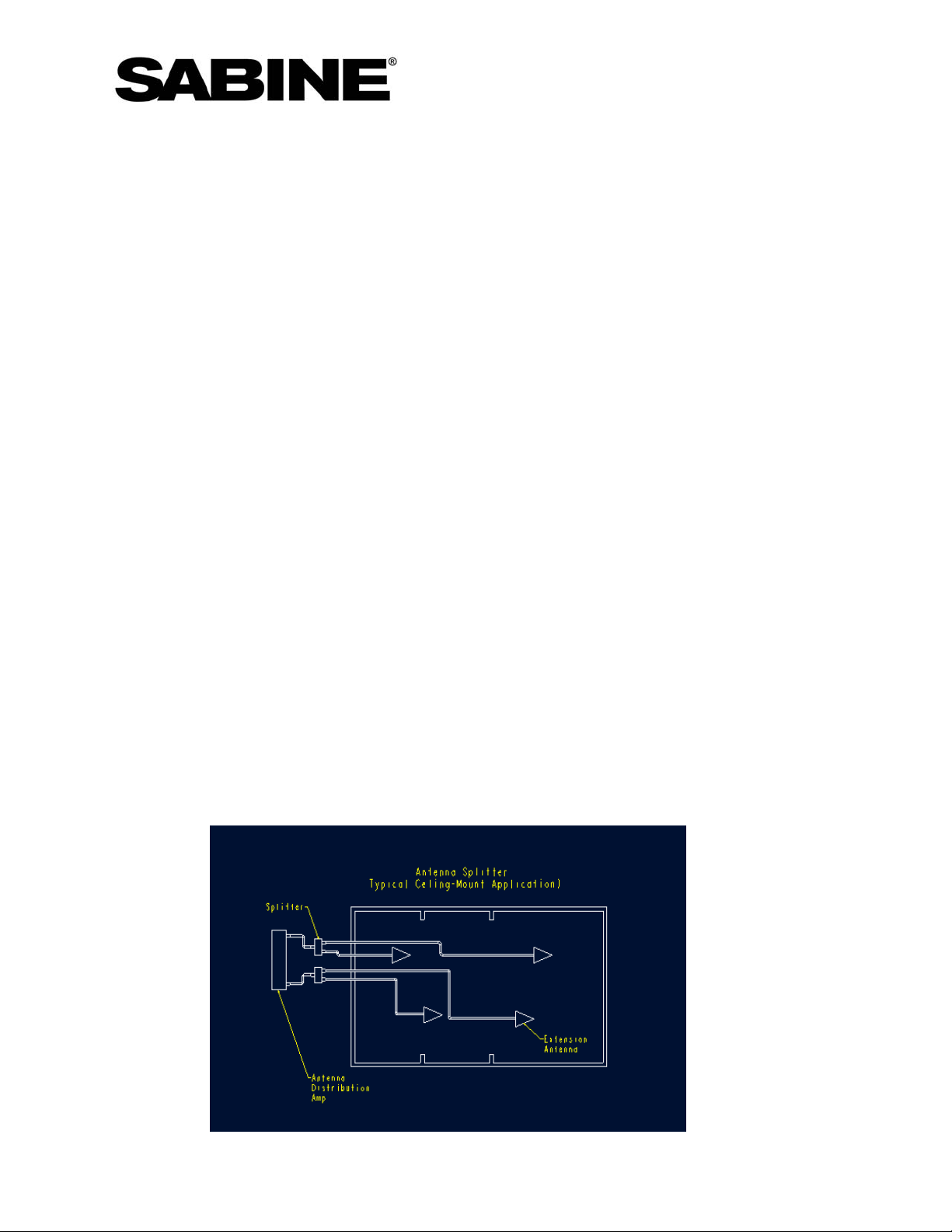
1.4.14. Antenna Splitter A number of articles have been published warning against
stringing antennas in series in an attempt to extend the operating range of a
wireless microphone system. They warn about dropouts resulting from comb-filter
interference. What these articles forget is that microphone systems have diversity.
The chance of both sets of antennas will experience a filter at the same location
and time is extremely low, especially if the antennas are offset as per the following
diagram:
Sabine Wireless: Application and Troubleshooting Guide 4 of 12
Page 5

1.4.15. We have successfully solved dropout problems using this technique in a very
large hall using 77 meter cable runs. Please note that high-gain extension
antennas are required to overcome the loss of the splitter and please note that you
must preserve diversity. The splitter we recommend can be found here:
http://www.hyperlinktech.com/web/signal_splitters_2400_2way.php
1.4.16. You can also daisy-chain two antennas on one cable length by moving the
splitter from the ADA to the first antenna.
1.4.17. Testing Your Antenna System. It only takes a few minutes to test your
extension antennas, antenna cabling, and antenna distribution amp. Eliminate
them from the system by simply placing a receiver on the stage with the dipole
antennas. Check your RF performance (Use powered speakers patched directly to
the receiver if you cannot connect to your sound system. If your dropouts go away,
you know the problem is with the antenna system.
2. RF Interference.
2.1. Outside sources of RF in the 2.4 GHz band can interfere with your wireless
microphone system if the outside source is strong compared to the transmitter’s signal.
Interference can cause dropouts or ticking and sputtering sounds in the audio. Possible
sources of 2.4 GHz interference include wireless LANs, some cordless phone,
microwave ovens, cordless security systems, wireless system control panels, such as,
Crestron and AMX, etc.
If you use the wireless systems in a room with a WiFi device close to the receiver, the
systems will work perfectly when the transmitters are close to the receiver. But as they
walk away, the transmitter signal level may eventually drop below the WiFi signal level
causing the system to squelch. The easiest way to overcome this problem is to
reallocate the WiFi to higher frequencies and leave the lower channels for the Sabine
system. Alternatively move the WiFi and the receiver away from each other. If these
solutions are not practical, we will soon offer directional antennas that reject off axis
WiFi signals.
2.2. 2.4 GHz transmitters signal strengths are limited by governmental regulations. If the
source of the interference is 50 feet or so farther from the antenna than the microphone,
you will rarely hear interference.
2.3. The best way to locate clear channels and avoid outside interference is to turn off the
Sabine mics and then run the scan function in Sabine Remote. Turn on all known
possible sources of RF interference in your area. Is there a microwave oven nearby? If
so, put a cup of water in it and run it while you scan. The scanner lets you block out
channels that have interference.
2.4. The next best way to locate clear channels If you cannot run a scan but you hear
interference, change to different RF channels. Move at least ten channels up or down
to avoid a single spread-spectrum source.
2.5. Generally it is best to clump the system’s channels close together at the low or
high end of the spectrum, i.e. channels 1, 2,3,4,5 or channels 65, 66, 67, 68. If there
Sabine Wireless: Application and Troubleshooting Guide 5 of 12
Page 6

is another 2.4 GHz source in the room, clumping the channels reduces the chances of
an overlap.
2.6. Many hotels, i.e., Hilton & Hampton Inn are now providing WLAN throughout their
facilities so that customers can log on to the internet from anywhere in the hotel.
These LANs, at least in the US, are restricted above our channel 10 and below our
channel 53. This is just one more reason that our customers should clump the
channels together at channels 70, 69, 68... on down to 54 and from Channels 1,
2,.3, up to 9.
2.7. Some Crestron system controllers with RF interfaces are set at the factory to spread
signal throughout the entire 2.4GHz band. Not only will this interfere with the
SWM7000, it will interfere with your LAN, Bluetooth, etc devices. Crestron gives
instructions explaining how the reconfigure their controller so that it only uses 1/7 of the
spectrum (www.crestron.com
). This leaves plenty of room for your SWM7000 system
and Crestron to work together without interference. Many other spread-spectrum
devices also allow you to reconfigure their transmission bands.
2.8. Procedure for Shifting the RF band: Sometimes it is difficult to determine if a wireless
microphone is experiencing 2.4GHz interference or if there is some other problem. We
have added a feature that allows a technician to temporarily shift the frequency of the
system partially out of the standard 2.4GHz band. If the interference goes away after
shifting, then you are experiencing interference with your wireless LAN or other 2.4GHz
equipment. If the interference does not go away, then the problem may be with cellphone interference or the system may require servicing. In general, down-shifting
works better than up-shifting.
Shifting Transmitters
(Requires handheld firmware version 2.08 or higher, or beltpack firmware version 1.27 or
higher).
• To change the frequency groups, open the transmitter door and hold down the
UP button while powering on the transmitter. Let go of the UP button after four
seconds and use the UP or DOWN buttons to scroll through the three choices
shown below in “Display in Setup.” These vary depending on your transmitter, as
shown. Allow the unit to finish powering up and it will be set for your selected
band. To confirm each one you should see the values shown in “Display in Use”
on the transmitter LCD:
Display in Setup Display in Use
DOWNSHIFTED FL
STANDARD F Channel number is shown F1 Channel number is left justified
UPSHIFTED FH
SW75-T SW70-H and SW70-T
Display in
Setup Display in Use
Channel number shown with
"L" to the left
Channel number shown with
"H" to the left
F0
F2 Channel number is right justified
justified with small minus sign to the left
Channel number is right
Sabine Wireless: Application and Troubleshooting Guide 6 of 12
Page 7

Shifting Receivers
(Requires firmware version 2.88 or higher, and software version 2.23 or higher)
• Use the software to make the change in the receivers. With the receiver
connected to your computer and the SWM7000 Remote Software running, hit AltC and then type the following when asked for a password:
o For F0 (down-shifted) type: chanlo
o For F1 (standard) type : channormal
o For F2: (up-shifted) type: chanhi
• A minus sign (-) will precede the channel number on the receiver and the
software if the frequency is shifted down (F0), and a plus sign (+) will show if the
frequency is shifted up.
Important note: Both the transmitters and receivers must be shifted together. Downshifted channel 44 corresponds to normal channel 1. Anything below channel 44 is out
of the license-free zone. Channel 44 and above are still inside the license-free zone. It
is important to note that some receivers will not operate reliably below channel 15. We
recommend channels 20 through 40 for testing.
Up-shifted channel 42 corresponds to normal channel 70. Selecting any channel above
42 takes you out of the license-free band. Channel 42 and below are still in the licensefree zone. We recommend temporarily using channels 50 through 65 for testing.
Note: When shifting a receiver, start by choose a channel within the area you are
shifting to.
3. Sound Quality
3.1. If your SWM7000 system does not sound as good as a wired mic, something is out
of adjustment. The first thing to try is to plug a wired mic into the receiver’s audio-out
cord. If the system still sounds bad, your problem is downstream of the receiver.
Check your other equipment. Try bypassing your EQ first, then the compressor, etc.
3.2. If the problem is definitely with the SMW7000, bypass all functions to identify the
cause. Bypass the FBX, set the compressor ratio to 1:1, set the de-esser to 0, set the
mic model to NONE, set the output level to -10dB, or simply load the System Default
program. If the system sounds better, first try resetting the FBX. Then add the other
functions in one at a time until you find the function that is out of adjustment.
3.3. The default PAD setting on the transmitter may be too high for loud programs or very
hot belt-pack mics. This will cause clipping and distortion. If so, open the case,
press select until the pad blinks and use the down arrow to set a deeper pad setting.
Pad settings range from 0 (no pad) to -40 dB (recommended for high-output mics such
as the Voice Technologies SVT70 series available from Sabine).
3.4. Two mics on the same channel If you turn on a mic and it screeches and sounds
grossly distorted, there is probably another mic on that some channel within 100
meters. Turn off the other mic or change channels.
Sabine Wireless: Application and Troubleshooting Guide 7 of 12
Page 8

3.5. RF is Strong But There Is No Audio Output
3.5.1. If there is no output with several transmitters, the problem is mostly with the
receiver. If your receiver is showing audio input in the LCD window, check your
output level on the front panel. Current versions of the receiver show the maximum
output level as +10 and mute as ---. Older versions show mute as -00.
3.6. If the system still does not sound good with all of the functions turned off, call Sabine at
386 418 2000.
4. Battery Charging System
4.1. Rechargeable batteries do not obtain their full performance until after about five full
charging cycles. Sabine performs this cycling on batteries before shipping. Your
batteries should deliver about eight hours of continuous service. The manufacturer
states that they are good for about 250 cycles. Replace them when their performance
starts to degrade. Alkaline batteries last on average 10 hours.
4.2. My batteries will not charge. The transmitter display shows only one square flashing
after the power supply is connected. That display indicates the pre-charge testing
of the battery. We do this to make sure we do not attempt to charge a nonrechargeable battery. This may take a while, so check back after about 25 minutes. If
charging does not begin (indicated by a scrolling battery display on the transmitter),
then call Sabine for technical support.
4.3. My batteries do not last long. Install new batteries. If they are new it will take 4
charging cycles before they reach their full potential. If the batteries get very hot turn off
the unit and immediately take out the batteries. This indicates there is a short in the
transmitter. Call Sabine customer service for assistance.
5. Receiver
5.1. Front Panel Controls do not work. Check to see if the word LOCKED appears in the
LCD Function Display message when you turn a knob or push a button. If so then the
front panel has been locked out. Raise DIP switch 5 and 6 to defeat front panel locks.
See the manual for more details.
Some receivers have a front panel that occasionally locks up when they get hot. The
audio will not be disturbed, but you will not be able to change the settings until after
turning the receiver off and back on. The receiver can still be controlled by a computer
when the front panel is locked. Try spacing the receivers apart or other cooling
methods or return the receiver to Sabine for a free upgrade. Call customer service.
5.2. Hard Reset: Use this only after consulting Sabine customer service. Press the A
channel SELECT (the blue button) and FBX Bypass while powering up the unit.
Warning: This also clears all user-saved presets.
Sabine Wireless: Application and Troubleshooting Guide 8 of 12
Page 9

6. Transmitter
6.1. The switch is programmable to guard against users with nervous fingers. Refer to the
Internal Control of External Switch on page 14 of the manual to see how this switch may
be set to “On/Off,” On/Mute,” or “On/On.”
6.2. Why does the Front Panel Display on the Receiver and the Software Interface
display different a microphone element from actual one on transmitter? The
handheld transmitters have a setting that tells the receiver which microphone capsule is
connected to the handheld transmitter so that mic modeling works correctly. You can
check and see if this is correct by holding down the Select button on the transmitter
while turning on the power switch. The capsule type is displayed (for example: H13).
Use the Up/Down buttons to select the capsule that matches the label on your capsule.
In order to record this change in memory, you must set another parameter before
turning off the mic. We suggest briefly changing the RF channel, then changing it back.
Now your new capsule setting is saved to memory.
6.3. Some mics have outputs that are so hot the belt-pack transmitter mutes. Increase
the PAD to solve this problem.
7. Sabine Remote Software
7.1. Upgrade your software if you have problems connecting. See the Upgrade section
below.
7.2. Each receiver can be controlled by Sabine Remote software on a PC computer, even if
it is not an ND series. Apple computers are not supported, although some customers
report good results with PC emulation programs.
7.3. Connecting more than one receiver to a network: You can control of up to 35 NDseries receivers with a single computer. Connect the computer to any receiver in the
rack with either an RS232 or USB connector. Set its DIP switch #7 down to
designate it as the master in the network. Connect all of the other receivers with the
RS485 connectors provided with the ND receivers. Set all of the rest of the receivers
DIP switch #7 up to designate they are slaves. Please note, the receiver only reads
the dip switches when the receiver is turned on. If you move a switch, you must turn
the receiver off and on before the switch setting goes into effect.
7.4. Dip Switch #1 must be down. Otherwise automatic squelch will be turned off and you
will hear a lot of noise. See the manual for other dip switch settings.
7.5. The ends of your RS232 cable should have pins 2, 3 and 7 wired together. Check
continuity.
7.6. DELL Computers seem to have special problems: Some RS232 to USB cables don’t
work. We have found that the GoldX RS232 to USB converter cable model GXMU1200
works with no problems.
Sabine Wireless: Application and Troubleshooting Guide 9 of 12
Page 10

7.7. If you are using the USB cable make sure you choose USB Connection as you are
clicking through the software prompts.
7.8. Here is how to check to see if the USB is connected properly::
• Connect the receiver to the PC with a USB cable; make sure the receiver is on.
• In Windows, go to Control Panel, Systems, Hardware, Device Manager, and click
on ‘Universal Serial Bus controllers’.
• If the receiver is connected properly, ‘Sabine SWM7000-USB is Ready’ will be
listed. If this is not there, then the receiver is not connected to the PC correctly.
7.9. If you still have a problem connecting your computer to the receiver, write down the
make and model of your computer, the operating system (Windows 2000, XP, etc.), and
call Sabine.
7.10. Some Dell laptops have conflicts with the serial port that cause it to shutdown after a
while. Try altering settings on the serial port, disable any other serial devices (cell
phones, Palm Pilots, etc.), or disabling the infrared connection, which can be sharing
the same serial port as the receiver.
7.11. Additionally make sure you disable the sleep mode on your computer.
7.12. Lost connection message? This may appear momentarily -- the receiver will usually
reconnect on its own right away. This message will appear if the receiver is turned off
or a cable is disconnected.
7.13. Initial software window opens, but software crashes when you select Demo Mode?
Your computer may not have enough memory to load all 35 receivers displayed in
Demo Mode. Run the software, but pull down the Help Menu before you select Demo
Mode. Select “Demo Mode Options” and choose a smaller number of receivers. For
example, try 10. This should fix the problem.
7.14. Graphics look wrong and elements overlapping? This may occur on Windows XP
computers. Check the Properties of the video (right click on the desktop), click to
Settings, Advanced, and check the DPI setting for the screen. It must be at 96 DPI, not
120, which can cause the problem.
7.15. RF channel appears to change after RF scan? If the RF scan function is interrupted
in some way or if you exit the scan without first selecting STOP, the receiver may not
return to its original channel. Check the RF channel knob and re-select the correct RF
channel. You can avoid this problem by always using the STOP button before you exit
the RF Scan section of the software.
7.16. Difficulty connecting to receivers? First use the instructions below to upgrade
your Sabine Remote software. Try cycling the power on your receivers. Check your
serial or USB cables for faults. Make certain you have selected the correct serial port or
USB connection from the opening Sabine Remote menu before you attempt to make a
connection to the receiver(s).
You may need to manually show your computer the location of the USB driver for your
SWM7000 receiver. This should happen automatically, but occasionally you will have
Sabine Wireless: Application and Troubleshooting Guide 10 of 12
Page 11

to do the following: Connect your receiver to your computer using the USB connection.
You should see a Windows display indicating a USB device has been found. Click on
the display and you should get a Windows Wizard asking to install this new device.
Follow the on-screen instructions. When you are prompted to choose the location of
the driver, choose browse. Your driver will be in the Windows/System32 directory on
your computer. Choose that directory. This should successfully install the driver. Due
to a quirk in Windows you may need to repeat the process again in order for your
receiver to connect.
8. Upgrading receiver firmware and remote control software
8.1. The first step to solving problems is to be certain that you have installed the latest
versions of the SWM7000 receiver firmware and Sabine Remote computer control
software. The receiver’s firmware version flashes in its LCD window a few seconds the
power is turned on. If the version is less than V2.68, you may experience occasional
dropouts!! Using a PC connected to the internet, download the Sabine Upgrade
Wizard from the following link and follow the instructions carefully. Always follow the
Wizard’s suggestions. http://www.sabine.com/resources/downloads-software.htm
Use the Wizard to upgrade Sabine Remote computer control software.
8.2. Any receivers with serial numbers below 12000 will only upgrade the DSP processor.
Contact Sabine for specifics.
8.3. After upgrading older receivers, the LCD display sometimes shows strange characters.
This is because some old firmware versions did not assign names to channels, but the
newer upgraded versions do. The easiest way to fix this is to do a hard reset (hold in
the channel “A” Contrast and “Bypass” buttons at the same time as you power on the
unit). This will assign names to channel A and B of “CHAN A” and “CHAN B”.
8.4. Digital Audio The SWM7000 provides for digital audio output and complies with the
following AES/EBU conventions:
Audio sample word = 16 to 24bit, SWM7000 = 24bit. Signal Amplitude = 2 to
7Vpp, SWM7000 = 5Vpp. The signal amplitude should be measured across a
110 ohm load without any interconnecting cables. See AES3 documentation.
The digital sync input is classified as a Digital Audio Reference Signal (DARS)
which follows conformity with AES11. The IC being used on the SWM7000 is a
Crystal CS8420.
The SWM7000 does not support Wordclock. The BNC connector on the receiver
is an AES synchronization input. Typically, this input is an XLR connector, so
Sabine provides a BNC to XLR adaptor (part number: SWC-BNC-XLR).
There is one known bug on some receivers. Each digital frame includes the
clock bit rate. The SWM7000 incorrectly sends the rate as 44.1KHz when it is
actually 48KHz. The user must override this by setting the correct bit rate to
48KHz on the receiving device. Receiver codes V2.88 and higher have fixed this
issue.
Sabine Wireless: Application and Troubleshooting Guide 11 of 12
Page 12

9. Dip Switches
Default positions are down. Conditions below engage when the switches are up.
DIP1 = Squelch Defeat
DIP2 = Channel A phase invert
DIP3 = MIC/GUI Level Change Defeat
DIP4 = Digital Output Clock Source (up = external)
DIP5 = Lock 1 (locks all front panel functions)
DIP6 = Lock 2 (locks functions selected in software)
DIP7 = Networking Master/Slave Select (up = slave)
DIP8 = Channel B phase invert
10. Customer Service.
For all other questions contact Sabine Service Department:
Phone (USA) 386 418 2000
E-Mail Sabine@Sabine.com
Sabine, Inc.
13301 Highway 441
Alachua, FL 32605 USA
www.Sabine.com
Sabine Wireless: Application and Troubleshooting Guide 080404 12 of 12
 Loading...