

SABINE SWM7000, SWM6000 Operating Manual

Operating Guide
SWM6000 915 MHz Systems
SWM7000 2.4 GHz Systems
WIRELESS MICROPHONES
the sound of innovation™
WIRELESS SYSTEMS


3
Sabine Smart Spectrum® Wireless
LIT-SWM6-7000-OG-EN-110203.indd
© 2011 Sabine, Inc.
Declaration of Conformity
EC - DECLARATION OF CONFORMITY
CE Ma r k i n g
We, the Manufacturer
SABINE, INC.
13301 NW US HIGHWAY 441
ALACHUA, FLORIDA USA
declare that the products
Receiver: SABINE MODEL SWM7000
Is in conformity with
Council Directive: 73/23/EEC and 89/336/EEC (EMC Directives)
Standards to which conformity is declared:
EN 60065: 2001
EN 55022: 1998 Class B
EN 50082-1: 1998
Transmitters: SABINE MODEL SW70-H and SW75-T
Is in conformity with
Council Directive: 73/23/EEC and 89/336/EEC (EMC Directives)
Standards to which conformity is declared:
EN 300422-1, 2
EN 300440-1
EN 301489-9
Manufacturer Signature: __________________________
Date: __________ Name: __________________________
Doran Oster, President
28 April, 2003

4
Sabine Smart Spectrum® Wireless
© 2011 Sabine, Inc.
Table of Contents
This operating guide written for receivers using Sabine SWM Remote Control
Software version 2.0 and above.
9. DE-ESSER 33
9.1. De-mystifying De-essers 33
9.2. The Sabine De-esser 33
9.3. Using the De-esser 33
10. PROGRAM SAVE & RECALL 34
10.1. Saving a Preset 34
10.2. Loading a Preset 34
10.3. Naming a Preset 34
10.4. Power Off Memory 34
11. MULTIPLE SYSTEMS OPERATION 35
11.1. Overview 35
11.1.1. Multiple System Interference 35
11.1.2. Setup Complexity 35
11.2. Antenna Distribution Amplier 36
11.3. Antenna Distribution Amplier Connection 36
12. EXTENSION ANTENNAS 38
12.1. Overview 38
12.2. Antenna Cabling & Cable Loss 38
13. REMOTE CONTROL OPERATION 40
13.1. Overview 40
13.1.1. Single vs. Multiple Receiver Control 40
13.1.2 Features & Controls Added Software 40
13.1.3. Software Multiple Unit Control 42
13.2. Software Installation 42
13.2.1. Requirements & Recommendations 42
13.2.2. Connections 42
13.2.3. Installing the Software 43
13.3. Launching the software 43
13.3.1. Off-Line Edit/Demo 43
13.3.2. Connecting Receivers. 43
13.4. Remote Control Operation 44
13.4.1. Two Views, Two Sets of Controls 44
13.4.2. Menus, Icons & Hot Keys 44
14. TIPS & TROUBLESHOOTING 48
14.1. Tips for Maximum Performance 48
14.2. Troubleshooting 48
14.3. Common Sources of RF Interference 49
14.3.1 RF Sources 49
15. FBX THEORY & PRACTICE 51
15.1. Introduction to FBX® 51
15.2. The Advantages of FBX Filters 51
15.3. Parametric Filters and FBX 52
15.3.1. The FBX & True Mobility® Advantage 53
14.3.2. FBX Fixed & Dynamic Filters 53
14.3.3. FBX Filter Width 54
14.3.4. Who Benefits from FBX? 54
15. APPENDICES 55
Appendix A: Beltpack Connector Wiring Diagrams 55
Appendix B: Antenna System Diagrams 55
Appendix C: Specications 56
Appendix D: Dip Switch Settings 58
Appendix E: Frequency Chart 59
Appendix F: Battery Endurance Tests (Typical) 60
Appendix G: Changing Audix Mic Capsules (SW70-H) 60
16. CAUTIONS & WARRANTY 61
INDEX 63
1. INTRODUCTION 5
1.1. Section Contents 5
2. PRODUCT VIEWS 6
2.1. Receivers 6
2.1.1. Front panel views 6
2.1.2. Back panel Views 6
2.2. Transmitters 7
2.2.1. Handheld 7
2.2.2. Beltpack 7
2.3. Components 7
3. QUICK SETUPS 8
3.1. Receiver & Transmitter Quick Setup 8
3.2. FBX Quick Setup 8
3.3. Tips for Good RF Performance 12
3.4. Common Sources of RF Interference 12
4. TRANSMITTER OPERATION 14
4.1. First step
14
4.2. Displays and Settings
14
4.2.1. LCD Display
14
4.2.2. Accessing Transmitter Controls 15
4.2.3. Adjusting Transmitter Settings 16
4.2.4. Transmitter Battery Management 17
5. RECEIVER OPERATION 20
5.1. LCD Display. 20
5.2. Parameter Control & LCD Display 22
5.2.1. One set of Controls for 1 or 2 Channels 22
5.2.2. Channel Select / Contrast Button. 22
5.2.3. Special LCD Display Messages. 23
5.3. RF Channel Select 23
5.4. Output Level 23
5.5. Channel Mixing 23
5.5.1. How to toggle channel mixing mode 23
5.5.2. Controlling the reciever in channel mixing mode 24
5.6. Guitar Cord Simulating 24
5.7. Receiver Antenna Placement 24
5.7.1. Multi-path Interference 24
5.7.2. Receiver & Antenna Placement Tips 24
6. MIC SUPERMODELING™ 26
6.1. Introduction 26
6.2. Emulation Choices 26
6.3. Mic Modeling Front Panel Control 26
6.4. Future Microphone Modeling Choices 27
6.4.1. Mic Model Upgrade Instructions 27
7. FBX FEEDBACK EXTERMINATOR® 28
7.1. FBX Introduction 28
7.1.1. FBX Fixed Filters 28
7.1.2. FBX Dynamic Filters 28
7.1.3. Balancing Fixed & Dynamic Filters 28
7.1.4. FBX Filter Width 28
7.2. FBX Set Up 28
7.2. FBX Bypass Button 29
8. COMPRESSOR/LIMITER OPERATION 30
8.1. Basics of Compression 30
8.2. Using the Compressor 30
8.3. Suggested Compression Settings 31
8.3.1. Vocal Settings 31
8.3.2. Guitar Settings 31

5
Sabine Smart Spectrum® Wireless
LIT-SWM6-7000-OG-EN-110203.indd
© 2011 Sabine, Inc.
1. INTRODUCTION
Congratulations on purchasing your Sabine Smart Spectrum True Mobility™ Wireless System. True Mobility™ Wireless Systems give you all the built-in processing you need on every microphone, and offer unique and powerful features unavailable
with any other wireless microphone.
1.1. Section Contents
Section 2 Product Views — illustrates system components (front & back panel views, transmitters, accessory lists and
part numbers).
Section 3 Quick Setup — gives the Quick Setup procedures for Receiver & Transmitter Operation and using the FBX
Feedback Exterminator®. Note that there is also a quick-start label on top of your True Mobility receiver for
the Sabine FBX Feedback Exterminator®, Compressor/Limiter and De-Esser functions.
Section 4 Transmitter Operation — details transmitter setup and operation.
Section 5 Receiver Operation — details receiver installation and setup.
Section 6 Mic SuperModeling™ — explains the use of the Sabine Mic SuperModeling™ and lists the microphones
modeled.
Section 7 FBX Feedback Exterminator® — explains how to set up your FBX filters.
Section 8 Compressor/Limiter — explains the use of the Compressor.
Section 9 De-Esser — details operation of the adaptive De-Esser.
Section 10 Program Save & Recall — explains how to save and recall individual program settings.
Section 11 Multiple Systems — how multiple systems interface, computer control of multiple systems, suggestions for
maximizing the number of collocated systems.
Section 12 Extension Antennas — how to get maximum performance using a Sabine Extension Antennas (Antenna
Distribution Amplifier also available for multi-receiver installations).
Section 13 Sabine Remote Control Software — how to control up to 70 channels from one PC.
Section 14 Tips & Troubleshooting — gives tips on how to get the best performance from your Sabine Wireless, and
describes some possible operating problems and their solutions.
Section 15 Appendices — wiring diagrams, frequency charts, specifications, typical system diagrams and dip switch
settings for Sabine Wireless systems.
Section 16 Cautions & Warranties — states caution and warranty information for your True Mobility™ Wireless sys-
tem.
Index
Introduction
Important note about using this Operating Guide
This guide covers the operation of both the SWM6000 and SWM7000 Wireless Systems.
The basic operating procedures for these two series are the same. The crucial differences
are the frequency bands each of these series uses, and the number of available channels.
SWM6000: Offers 34 channels, and uses the 915 MHz band. All transmitters and receiv-
ers include the number “6” or the designation “M9” in the part number to denote this series.
SWM7000: Offers 70 channels, and uses the 2.4 GHz band. All transmitters and receivers
include the number “7” or the designation “M1” in the part number to denote this series.
These products may be used together in the same location, but remember that transmitters
and receivers must always work together. For example, in order for an SWM6000 Series
system to work, the transmitters and receivers must both be from that series.
Other components in your system can be mixed between these two series. These include
lavalier and headworn mics, mic clips and chargers, cables and adaptors, and anything that is
not involved in the transmission or reception of the wireless signal.
6
Sabine Smart Spectrum® Wireless
© 2011 Sabine, Inc.
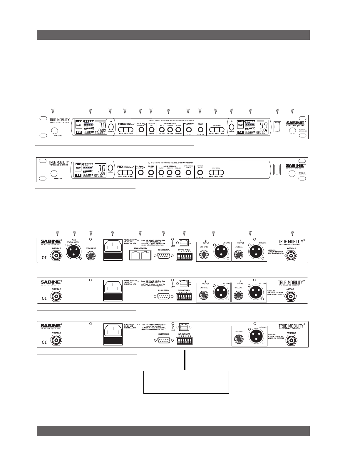
Product Views
Ch. A
Channel
Select,
Contrast
Ch. B
Channel
Select,
Contrast
Fig. 2b - SW71-R (SW62-R) One-channel Receiver
Fig. 2a - SW72-NDR & SW72-R (SW62-NDR & SW62-R) Two-channel Receivers
Antenna 1
Front Mount
Ch. A
Display
Antenna 2
Front Mount
PowerCh. B
Display
ProgramOutput
Level
RF Ch.
Select
Compressor
Limiter
De-
esser
Mic
Model
FBX
Fig. 2e - SW71-R (SW61-R) One-channel Receiver
Fig. 2d - SW72-R (SW62-R) Two-channel Receiver
Fig. 2c - SW72-NDR (SW62-NDR) Two-channel Receiver w/Network & Digital Interface
Antenna 2
AES3
Digital Output
Sync
Input
AC Power
& Fuses
RS485 Net-
work
RS232
Serial
USB Port,
Dip Switches
Mic/Line Balanced
Output B
Mic/Line Balanced
Output A
Antenna 1
2. PRODUCT VIEWS
2.1. Receivers
2.1.1. Front panel views
2.1.2. Back panel Views
See Page 55 for the chart
of DIP Switch Settings
7
Sabine Smart Spectrum® Wireless
LIT-SWM6-7000-OG-EN-110203.indd
© 2011 Sabine, Inc.
Product Views
Product Views
Fig. 2h - SWC70CL - SW70-H13 (SW60-H13), SW70-H15 (SW60-H15) & SW70-H19 (SW60-H19) Mic Clip with Built-in Charger
Fig. 2i - SW65 and 75-T Beltpack Transmitter
2.3. Components
(for a complete list see the Sabine Catalog)
Receivers
SW62 and 72-NDR: 2-Ch. Receiver w/Network & Digital Interface
SW62 and 72-R: 2-Ch. Receiver
SW61 and 71-R: 1-Ch. Receiver
Microphones
SWT31L-TA4: Cardioid Lavalier Mic
SWT56W-TA4: Headworn Mic
SVT70BW-TA4: Voice Technologies Omni Headworn Mic (Black)
SVT70LW-TA4: Voice Technologies Omni Headworn Mic (Tan)
SVT80BW-TA4: Voice Technologies Cardioid Headworn Mic (Black)
SWTVT50-TA4: Voice Technologies Miniature Omni Lavalier
SVT40L-TA4: Voice Technologies Sub-Mini Omni Lavalier
SWT70G-TA4: Instrument Input w/cable
Transmitters
SW65 and 75-T: Beltpack Transmitter
SW60 and 70-H13: Handheld Mic w/Dynamic Element (Audix OM3)
SW60 and 70-H15: Handheld Mic w/Dynamic Element (Audix OM5)
SW60 and 70-H19: Handheld Mic w/Condenser Element (VT)
Antennas
SWA700: TNC Front to Rear Converter Kit (Set of 2)
SWA6SS: Antenna Distribution Amp for 6 systems
SWASS-EXT: Extension Antenna Kit (Set of 2)
SWAANT: Dipole Antennas (2)
SWATNC-N: RF Adaptor cable, Set of 4, TNC to NB
SWATNC-MCA: TN C Male Crimp Connector 2.4 GHz
SWACA15(or 30)-TNC: RF Cables, RG58, TNC, One Pair
Batteries
SWBAA2: Rechargeable NiMH AA set for SW75-T & H1
Mic & Transmitter Accessories
SWCRJ45: RS485 Serial Cable for ND Receivers
SWC70CL-1: SW60/70-H Mic Holder w/Built-in Charger
SWC70CL-12: Stage clip for SW70-H
SWCPOWR-EXT: Charger extension cable (3 meters)
SWCPOWR: Plug-in charger for SW60/70 Series Transmitters
SWC4P-TA4: Standard Mini-XLR Connector
ALKALINE BATTERY CAUTION Alkaline batteries must be one of following types:
NEDA: 14A ANSI: 14A IEC: LR14
!!
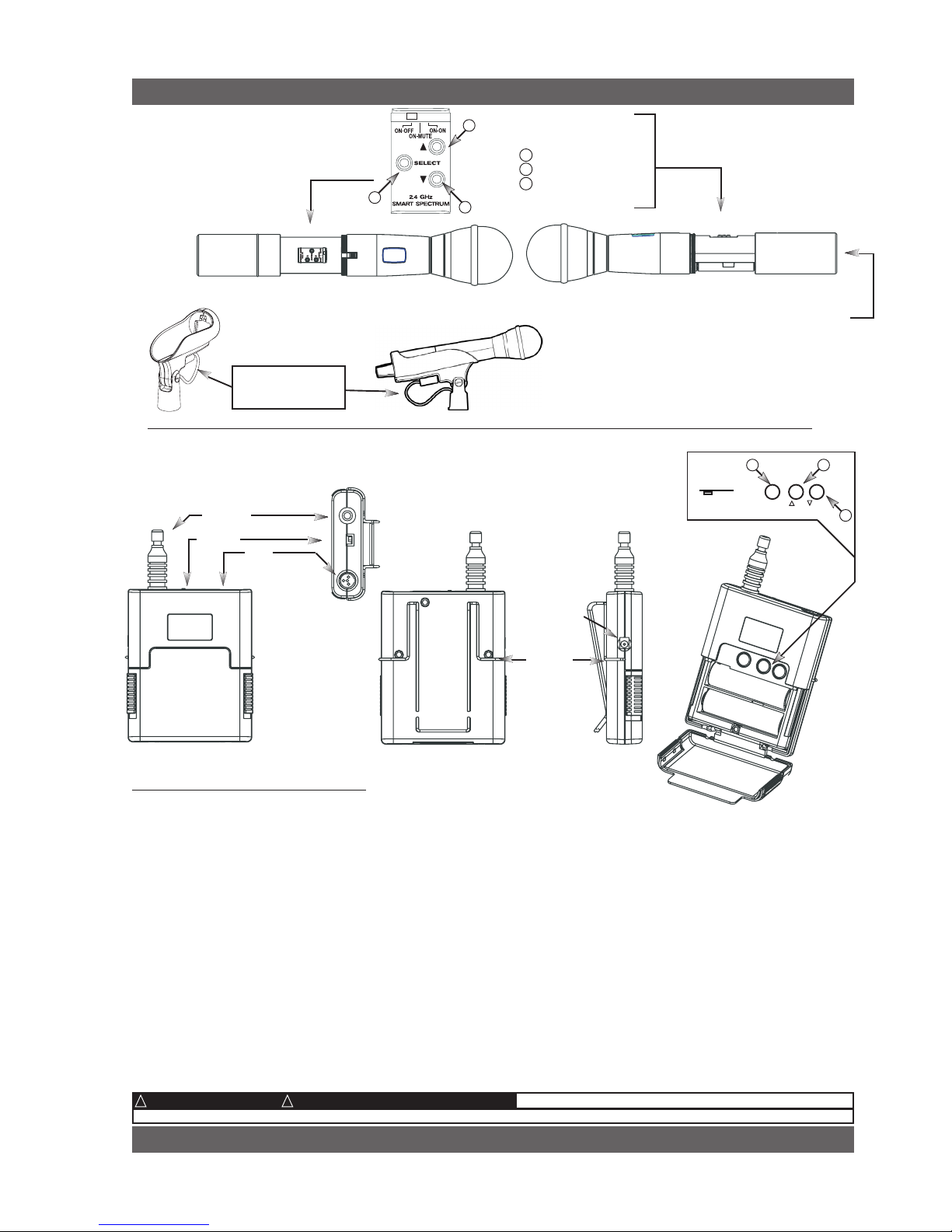
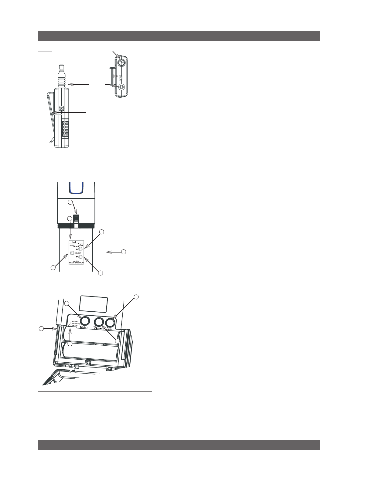
Antenna
Switch
TA4
Mini-XLR
Connector
Top view
Belt clip
SWC-POWR
plug-in charger jack
s el e c t
o n o n o n
o f f m ut e o n
2.4 GHz SMART SPECTRUM
1
2
Battery
SWC-POWR
plug-in charger jack
Shown with cable
attached. Requires
assembly.
Switch
Battery
LCD
Transmitter Controls
1 Select Button
2 Up Button
3 Down Button
2.2. Transmitters
2.2.1. Handheld
— DO NOT USE RECHARGEABLE ALKALINE BATTERIES —
2.2.2. Beltpack
1
2
3
u p
d o w n
3
(for a complete list see the Sabine Catalog)
8
Sabine Smart Spectrum® Wireless
© 2011 Sabine, Inc.
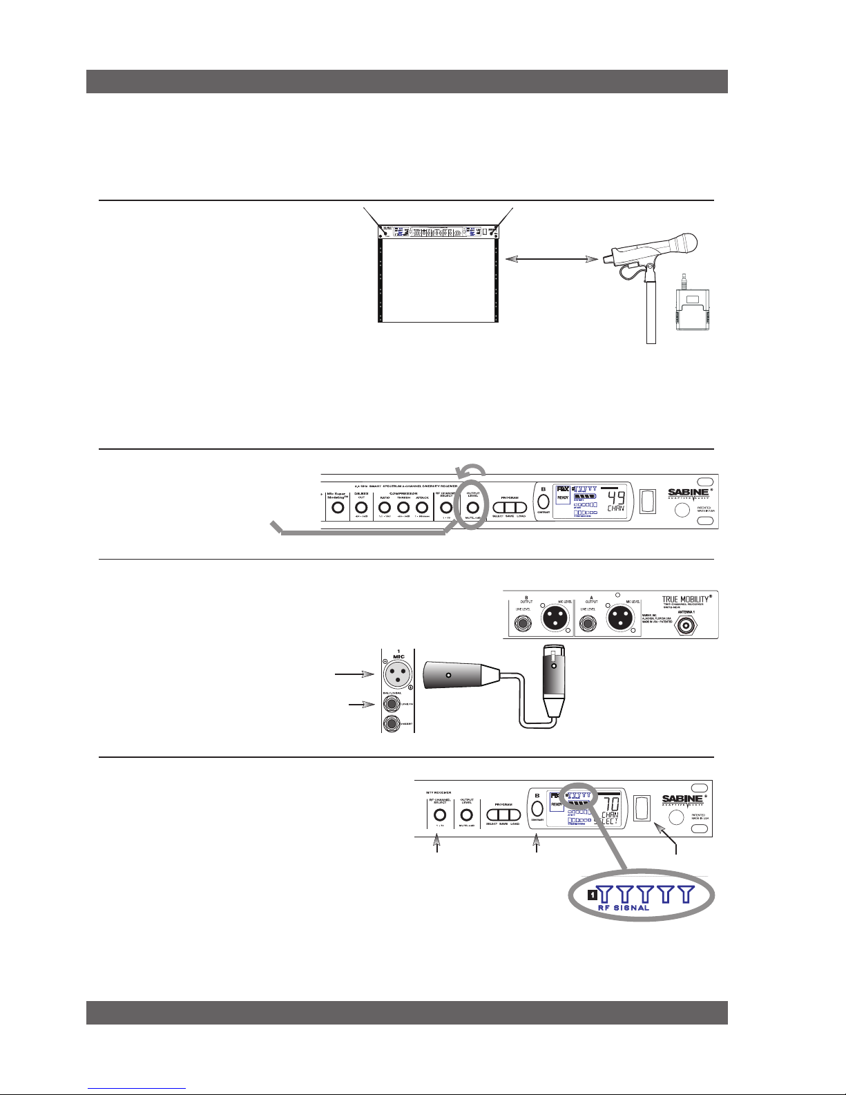
3. QUICK SETUPS
3.1. Receiver & Transmitter Quick Setup
Please read Section Four Transmitter Operation and Section Five Receiver Operation for a complete understanding of how to set up
your Sabine Smart Spectrum True MobilityTM System.
Quick Setups
Turn the OUTPUT LEVEL of the
receiver and mixer gain to the minimum settings.
2
Connect the output (¼-inch or XLR jack) of your receiver to the
mic or line input of your mixer or amplifier (the receiver output
gain can be adjusted to match the mixer input).
3
Mixer Balanced Input
(XLR)
Mixer Unbalanced Input
(TRS)
1. Turn on the receiver.
2. Tap the Channel Select/Contrast button to edit
a receiver channel. (Not necessary on 1-channel
SW71-R & SW61-R receivers).
3. Turn the RF Channel Selector knob to the desired channel.
NOTE: Dual channel receivers will not allow you to select
the same RF channel for both channels.
4
Power SwitchRF Channel
Selector
Channel Select/
Contrast button
(selects receiver
channel to edit)
Transmitter range is 100
meters line-of-sight
Be sure that all transmitters are off. Position receiver so that the antennas are within visual range of the intended
transmitter locations. Transmitter range is about 100 meters, but structural objects in the transmission path can reduce
that range. For best results, maintain a line-of-sight path between receiver antennas and transmitters (see Section
12). Use the TNC Rear-to-Front Kit (SWA700) included with the receiver to move antennas to front if necessary.
See Appendix B for more information on multiple-system connection.
Use Sabine’s SWASS-EXT
Extension Antenna Kit when
line-of-sight path is not possible
from receiver location.
1
NOTE: Front panel RF Signal display will only register Sabine transmitters. It will not show RF interference. Use the RF
Scan function in the software to scan for potential RF interference.
Selecting RF Channels: It is best to keep
the system’s channels close together at
the low or high end of the spectrum, i.e.
channels 1, 2, 3, 4, 5 or channels 65, 66, 67,
68 (31, 32, 33, 34 on SWM6000 series). If
there is another 915 MHz or 2.4 GHz source
in the room, grouping the channels reduces
the chances of an overlap. Do not start by
spreading your channels throughout the full
channel range of the system – you are more
likely to encounter interference this way.
9
Sabine Smart Spectrum® Wireless
LIT-SWM6-7000-OG-EN-110203.indd
© 2011 Sabine, Inc.
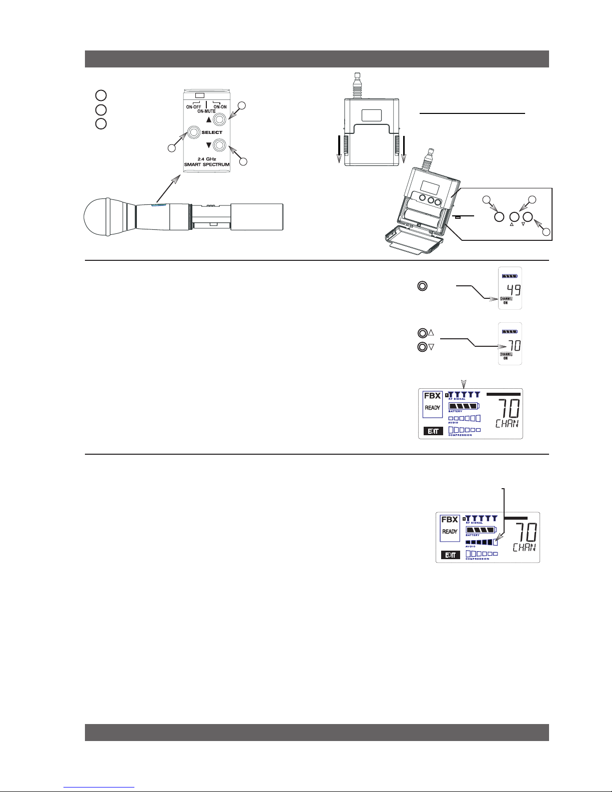
6
Gain Adjustment Settings
1. Transmitter (PAD Adjustment). Adjust the Transmitter PAD setting if
last segment of the Transmitter or Receiver Audio Level Meter lights up
often, or remains on when mic or beltpack is used.
1. Use the Transmitter Select button to scroll through functions
until PAD flashes in the Transmitter LCD.
2. Use the Up or Down buttons to select the desired setting. Selec-
tion is stored after 3 seconds of inactivity.
3. Check to see if Audio Level Meter stays out of Clipping Zone
1. Turn on the transmitter.
2. Use the SELECT button until CHANNEL appears in the LED. NOTE:
the transmitter is muted during editing.
3. Use the UP or DOWN button until the desired channel appears above
CHANNEL.
4. Check that the receiver’s RF SIGNAL display now indicates a strong
signal (at least 3 bars).
5
Quick Setups
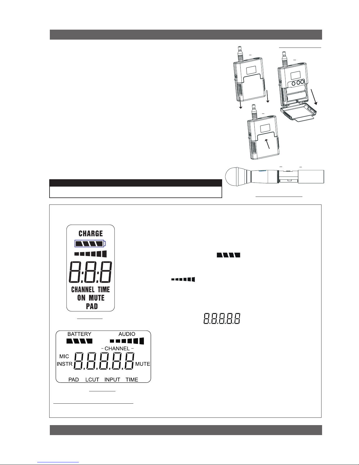
To Close: Push door up and snap
closed.
To Open: Pull down on both battery door
releases and then pull door open.
2. Receiver. Adjust the receiver Output Level to supply a strong input level to the mixer, amplifier or active loudspeaker. If your receiver output is connected to a microphone level input on the mixer, keep the receiver output gain
lower than when connecting to a line level mixer input. NOTE: -10 is a good place to start.
3. Mixer. Adjust the output gain of the mixer so that the mixer output meters approach clipping when all the inputs
to the mixer are active, and the audio program reaches its peak level.
4. Amplifier/active loudspeaker/crossover. Finally, adjust the amplifier gain control (and/or crossover gain, if one
is used) to provide the desired level of sound pressure in the auditorium or listening area.
Adjust PAD setting so that
Receiver Audio Level Meter
stays out of the clipping
zone (last segment)
SELECT
See Section 4.2.3 Adjusting Transmitter Settings for more information.
Transmitter Controls
1 Select Button
2 Up Button
3 Down Button
1
2
3
To Close: Turn the
ho usin g and push
up until it meets the
threads, then screw
on.
To Open: Unscrew
lower portion of microphone. Pull down
as you continue to
turn the housing.
s el e c t
o n o n o n
o f f m ut e o n
2.4 GHz SMART SPECTRUM
1
2
u p
d o w n
3
Beltpack Opening/Closing Instructions
10
Sabine Smart Spectrum® Wireless
© 2011 Sabine, Inc.
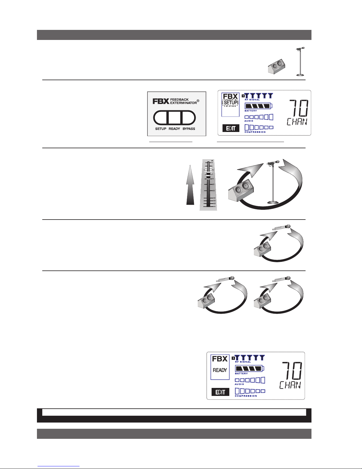
Fig. 3d - FBX: SETUP
Fig. 3e - SETUP indicator flashing
Quick Setups
3.2. FBX Quick Setup
Place microphone and speakers in primary position.
1
2
Press and hold the SETUP button (Fig.
3d) on the receiver until the LCD SETUP
indicator (Fig. 3e) flashes 4 times and
SETUP stays lit — then release it.
NOTE: DO NOT TALK INTO YOUR SYSTEM while in
Setup Mode.
Slowly raise the gain on the mixer or amp until FBX
eliminates the first few feedback tones. With each new
feedback frequency, you will hear a short, quiet burst of
feedback that will disappear immediately as a filter is
set.
Pause raising the gain, and move the microphone to another area where it will be used.
Resume slowly raising the mixer gain, until FBX eliminates a few more feedback tones.
NOTE: When choosing microphone setup locations, try to anticipate likely areas where
the microphone will be positioned or moved to, or areas that may be especially prone to
feedback problems (e.g., under an overhead speaker).
Location #1
Location #2
Location #3
Repeat until the SETUP indicator automatically turns off and
the READY indicator comes on.
NOTE: You may quit SETUP mode at any time prior to its auto-
matic exit by simply pressing the READY button. This will enable
ready-to-operate status, but with fewer fixed FBX filters in place.
In the default factory setting, dynamic FBX filters will still be held
in reserve to catch and eliminate new feedback, regardless of
how or when SETUP mode is exited. (See Section 14.3.2 for
details on the differences between fixed and dynamic FBX filters
and Section 13.4.2.1 for instructions on changing the balance
5
4
3
FBX BYPASS CAUTION
Bypassing FBX filters may allow suppressed feedback to be released!
Location #4
(if necessary)
Mixer Channel
of fixed versus dynamic FBX filters using the Remote Control Software or Appendix D for using the Dip Switches on
the back of the receiver).
3.2.2. FBX Bypass
The BYPASS button (Fig. 3d) bypasses only the FBX filters, and not
the additional signal processing (de-essing, compression and Mic
SuperModelingTM) available on the True MobilityTM Wireless Receiver.
This is a useful button that allows comparison of the sound quality
when FBX filters are in place, to the sound with no filters (the quality should be very similar). Before pressing BYPASS, take care
to reduce your overall system gain so that you do not release
suppressed feedback!
11
Sabine Smart Spectrum® Wireless
LIT-SWM6-7000-OG-EN-110203.indd
© 2011 Sabine, Inc.
Quick Setups
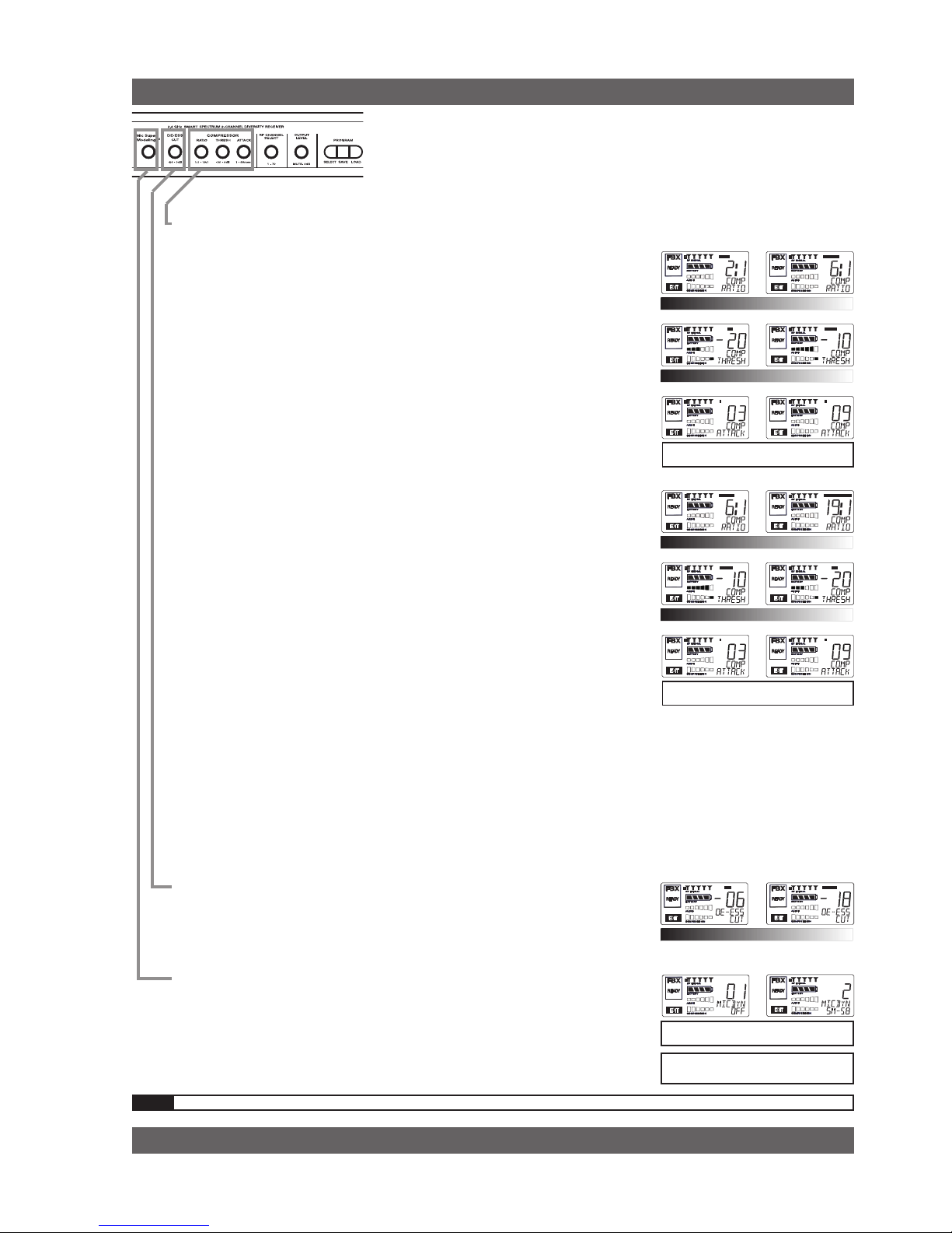
Vocal Settings
r a t i o A soft voice could be set to 2:1, whereas a loud voice might require
a ratio setting of 6:1.
t h r e s h The higher the threshold setting, the more signal is required to
initiate compression. Ideally this should be set to reign in peak
levels, and allow signals of lower gain to pass uncompressed.
Threshold settings will depend on the nature and variety of the
signal source.
a t t a c k Short attack times usually work well for voice. However, too strong
a compression ratio, too low a threshold, and too fast an attack
may attenuate speech consonants, which provide important intelligibility cues to the audience, thus compromising clarity.
Guitar Settings
r a t i o A high compression ratio (with gain makeup) will add sustain to
held notes and chords.
t h r e s h Moving the threshold will change the audible thick/thinness of
the guitar tone, but generally you want to compress all the notes
played.
a t t a c k Be wary of too quick an attack, which may reduce the percussive
attack of the guitar notes.
In general, be wary of too much gain makeup, and too high a compression
ratio, which may make a noisy guitar amplifier more objectionable. Ratio
settings might range from 6 to 19:1, threshold variable, slower attack, soft
knee, output gain boosted slightly to significantly depending on amount
of compression.
Bass Guitar Settings
r a t i o Set to 4:1
t h r e s h Set to compress peaks only.
a t t a c k Quick attack, medium release, hard knee; (try various release
settings, depending on the speed of notes played).
g a i n Output boosted slightly.
MIC SUPERMODELING
TM
DE-ESSER
r a t i o
t h r E s h
a t t a C k
r a t i o
t h r E s h
a t t a C k
NOTE: Use these settings as a place from which to start, then adjust to your own satisfaction.
Vocals
Short attack is better for vocals. Be careful not
to over attenuate speech consonants.
Soft voice Loud voice
Soft voice Loud voice
Guitar
Less Sustain More Sustain
Thinner sound Thicker sound
Be wary of too quick an attack, which may reduce the percussive attack of the guitar notes.
NOTE: Mic SuperModeling
t m
is not avail-
able using beltpack transmitters.
COMPRESSOR/LIMITER
M i C s u p E r M o d E l i n g
Scroll through available microphone settings. See
website for additional downloadable microphones.
Less reduction More reduction
d E -E s s E r

12
Sabine Smart Spectrum® Wireless
© 2011 Sabine, Inc.
Quick Setups
3.3. Tips for Good RF Performance
• Itisbestto keep the system’s channels close together at the low or high
end of the spectrum, i.e. channels 1, 2, 3, 4, 5 or channels 65, 66, 67, 68 (31,
32, 33, 34 on the SWM6000 series). If there are other 2.4 GHz or 915 MHz
sources in the room, grouping the channels reduces the chances of overlap.
Do not start by spreading your channels throughout the full channel range of
the system -- you are more likely to encounter interference this way.
• AvoidpotentialsourcesofRF interference by performing a scan using Sabine’s
Remote Control Software., which will reveal the ambient RF level in your
area on each channel of your system. Please refer to Section 13.4.2.5. for
information on the RF Scan function, which will automatically determine the
best RF channels to use.
• Ifyoucannotperformascan thenproceed touseyoursystem, beginning
with Channel 1. If you hear any RF “hits” or dropouts, then move to another
of the available channels. If you have multiple mics keep all your channels
grouped together.
• Forbestresults,maintainline-of-sightfromtransmittertoreceiver.Useeither
front or rear panel antenna mounting to maintain line-of-sight.
• Mountreceiverantennasat90degreestooneanother,leaningawayat45
degree angles, in the same plane.
• Whenusingmultiplereceivers,trytomaintainatleast1foot(30cm)distance
between antennas from different units. When such antenna spacing proves
difficult or impossible, we recommend using Sabine’s SWA6SS Antenna
Distribution Amplifier. The SWA6SS works with up to six receivers, or 12
channels.
• Maximizethedistancebetweenthereceiverandlightsources,suchasuorescent bulbs or neon signs, which may emit very short-range, broadband
interference.
• Maximize the distance betweentransmitters andreceivers and potential
sources of RF interference.
• Maintainaminimumdistanceofatleast3meters(10feet)betweentransmitters and receivers or extension antennas. This can solve many anomalies.
• Turnonyoursystemonecomponentatatime,beginningwiththerst receiver.
• Becarefulnottosetmorethanonetransmittertothesamechannel;each
paired transmitter and receiver should be set to unique corresponding channels, until all channels are receiving clearly and cleanly.
3.4. Common Sources of RF Interference
• Microwave ovens: In the vast majority of situations, interference from mi-
crowave ovens will not affect performance of your SWM series microphone
systems. Since barriers such as walls work to block interference, a microwave
oven will likely present a problem only when located in fairly close proximity
within the same room as the wireless receiver (or reception antenna). See
caution at left.
• Wireless Local Area Networks (WLANS): These computer network devices
allow computers to connect via wireless devices that act as both receivers and
transmitters. These low-powered transceivers often have selectable channels
and can utilize the entire 2.4 GHz band. In general, Sabine microphones
should not be affected by these WLANS because their spread spectrum
technology does not present a problem for the Sabine Smart SpectrumTM
system. The Sabine wireless system will not interfere with the WLAN. See
caution at left.
As a general precaution, keep 2.4 GHz or
900 MHz cordless telephones, microwave
ovens, WLAN antennas and 2.4 GHz
wireless video camera transmitters twice
the distance from your Sabine wireless
microphone system antennas as that of
your Sabine transmitters.
Antenna Placement Caution

13
Sabine Smart Spectrum® Wireless
LIT-SWM6-7000-OG-EN-110203.indd
© 2011 Sabine, Inc.
• 2.4 GHz or 900 MHz Cordless phones: These home telephones broadcast at very low
power and should not present interference problems for your Sabine wireless. This is
especially true if the telephone uses spread spectrum technology. See caution at left.
• Wireless Video Cameras: Certain wireless video cameras (X10, for example) use
the 2.4 GHz band. These devices are also very low power and, in general, should not
present a problem when using the SWM system. See Section 5 Receiver Operation for
methods of optimizing clear reception and minimizing interference. See caution at left.
In the event problems still arise, see Section 5 Receiver Operation for methods of optimizing
clear reception and minimizing interference.
Quick Setups
14
Sabine Smart Spectrum® Wireless
© 2011 Sabine, Inc.
4. TRANSMITTER OPERATION
4.1. First step
Before you begin, let’s look at a few basics regarding your transmitters. The
handheld mic is ready to go — the microphone and transmitter are combined
in one unit. To use the belt pack transmitter, however, you will have to connect a lavalier or headworn microphone (or instrument pickup) to its input.
Sabine lavalier and headworn mics, and Sabine’s guitar/instrument connector (SW70G-TA4) come equipped with the proper TA4F connector, and are
ready to plug right in. Be sure to line up the pins properly — do not force the
connector into the belt pack.
If you are using a different microphone with the Sabine belt pack, please refer
to the Appendix A for the required wiring plan. Failure to use the proper wiring
scheme may damage your mic or the belt pack, and void your warranty.
Use the clip on the back of the belt pack transmitter to attach it to your belt
or clothing. The spring clip can be removed and reversed, to allow the transmitter and antenna to point either up or down in its clipped-on position. You
can also remove the clip if you choose to keep the transmitter in your pocket.
NOTE: it is essential that transmitters retain a line-of-sight relationship with
the receiver antennas.
4.2. Displays and Settings
Your Sabine Smart Spectrum handheld microphone and belt pack transmitter have many powerful features, all of which are easily monitored (using the
transmitter LCD display) and adjusted. The controls and displays for both
handheld and belt pack transmitters are almost identical in function, though
positioning differs (compare figures 4b & 4c). The LCD display and one control
switch are located on the exterior of the transmitters. A more powerful set
of recessed controls is located under the hinged access panel, to prevent
accidental or inappropriate alteration of settings.
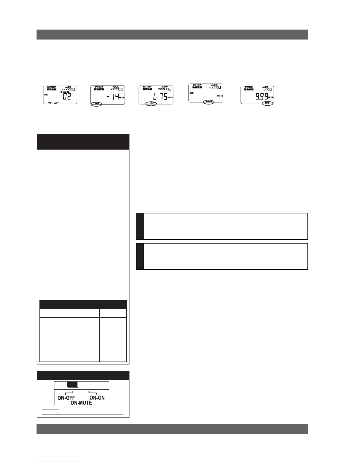
4.2.1. LCD Display
When the transmitter is first turned on, it shows an initial test screen (Fig. 4f),
followed by the default screen (Fig. 4g). The LCD also reverts to this default
display within a few seconds after any programming changes are made with
the recessed controls. The default LCD display always shows transmission
channel, audio level, and battery voltage level; additional information will
appear to indicate important changes caused either by user adjustments,
or automatically as transmitter status changes.
Fig. 4a
External
Switch
Fixed
Antenna
TA4F connector
Belt clip
1. Select Button
2. Up Button
3. Down Button
4. Programmable Control of External Switch
5. External Switch
6. Recessed control and battery compartments
Fig. 4c SW65 & 75-T Transmitter Control Setting Buttons
6
Fig. 4b SW-H series Handheld Control Setting
Buttons
2
4
5
1
3
Transmitter Operation
1
2
3
4
6
15
Sabine Smart Spectrum® Wireless
LIT-SWM6-7000-OG-EN-110203.indd
© 2011 Sabine, Inc.
4.2.2. Accessing Transmitter Controls
Control of all your transmitter functions is made using the Select button and
the Up/Down buttons. These control buttons are located inside the access
compartment on the beltpack or handheld transmitters.
Opening the Beltpack Transmitter Access Compartment:
1. Using your thumb and forefinger, grab both tabs and simultaneously pull
down toward the bottom of the beltpack. This releases the locks.
2. Gently pull the door open.
Closing the Beltpack Transmitter Access Compartment:
3. Swing the door back up and close it by firmly pushing the top part of the
door in until you hear the locks click.
Opening the Handheld Transmitter Access Compartment:
1. Unscrew lower portion of the case. Continue turning as you pull down.
Closing the Handheld Transmitter Access Compartment:
2. Begin by turning the lower portion of the case as you push up. When
threads meet screw on until snug.
NOTE: Do NOT attempt to unscrew the mic capsule from the body. This will
void your warranty!
CHARGE: Illuminates when the transmitter battery is being charged (i.e.,
when the charger is connected, either by direct plug-in or by placing the
handheld mic in the Sabine charging clip).
BATTERY VOLTAGE LEVEL METER: Indicates measured battery voltage;
the more segments illuminated, the higher the voltage, and the greater the
remaining battery life.
AUDIO LEVEL METER: Shows the audio output level of the transmitter
(affected by the pad setting).The last and largest segment indicates clipping.
PARAMETER VALUE: In default mode this indicates the RF TRANSMISSION CHANNEL chosen for the transmitter. In conjunction with the Select
button (see figures 4b & 4c), this field will also display battery run-time
hours, or when a low frequency roll-off filter or an attenuation (pad) is active (see Fig. 4g).
“TIME”: Displays when battery run-time hours are being displayed.
“MUTE”: Indicates output is currently muted.
“PAD”: Illuminates when the microphone pad is turned on. Use this if the
audio meter shows clipping.
“MIC” INSTR”: Indicates SW65 & 75-T beltpack (only) is set to accept
either mic or intrument input.
“ON”: Illuminates when either the audio and RF transmission, or the RF
transmission only, are turned on. (SW-H Series only)
“CHANNEL”: Illuminates in default mode to display transmission channel.
Fig. 4f: Start up Transmitter LCD displays
Transmitter LCD Display Indicators
Fig. 4d: SW65 & 75-T
Fig. 4e: SW60 and 70-H
Turn off transmitter before changing battery(s).
BEFORE CHANGING BATTERY
Transmitter Operation
1
2
3
1
2
SW-H Series
SW65 & 75-T
16
Sabine Smart Spectrum® Wireless
© 2011 Sabine, Inc.
4.2.3. Adjusting Transmitter Settings
DEFAULT/CHANNEL: Press the Select button to enter Edit Mode, and repeat
until the CHANNEL indicator flashes. In this mode, the Up/Down buttons will
adjust Transmission Channel.
INPUT: (SW65 & 75-T Beltpack Transmitter only) Either “MIC” or “INSTR” for
microphone or instrument. You are required to choose the input in order to
program both the transmitter and the receiver to optimize the input settings.
Choosing MIC automatically selects the 75 Hz roll-off filter. You can choose to
remove that but the extended low frequency response of the SW65 & 75-T may
reproduce too much low energy for your system, so beware. Choosing INSTR
automatically removes the 75 Hz roll off filter for that added bottom end in your
instruments. NOTE: You can manually change that filter setting as needed.
Electric Guitar/Bass & FBX: For best results, when using the SW65 &
75-T Beltpack Transmitter for electric guitar or bass, put your receiver’s
FBX Feedback Exterminator into BYPASS mode. FBX BYPASS is acces-
sible via the receiver front panel or Remote Software control.
PAD: Transmitter PAD setting. Press the Select button until the PAD indicator
flashes. The Up/Down buttons will adjust attenuation (SW-H Series) 0, -6, -14,
-20 dB; SW65 & 75-T: 0, -3, -6, -10, -14, -17, -20, -23, -26, -30, -34, -37, -40 dB).
When any level of attenuation is programmed, the default screen will illuminate
PAD. See margin notes on this page and p.15 for settings instructions.
TIME: Battery Run-Time Hours. Selecting this option changes the display to
indicate the length of power-on time (hours and minutes) since the last battery
change or recharge.
NOTE: Battery run-time hours will reset when the transmitter (with battery in
place) is connected to a charger. In the case of the charger, run-time hours
will not start again until the charger is disconnected. You can manually reset
the run-time hours by pressing both the up and down arrows. Use this to count
hours when you use alkaline batteries.
LOW FREQUENCY ROLL-OFF: Selecting this option adds a 12 dB/octave low
frequency roll-off filter, starting at 75 Hz, to the audio output of the transmitter.
A roll-off filter may help reduce microphone handling noise, or other unwanted
low frequency content. Pressing the Up or Down button toggles between the
conditions of no filter (indicated in the display as L 0) or low roll-off (indicated
by L 75).
INTERNAL CONTROL OF EXTERNAL SWITCH: The recessed controls
include a 3-position switch, which in turn determines how the transmitter’s
external two-position switch behaves (see figures 4a, 4b & 4h). From left-toright, the 3 positions of the internal switch correspond to the following external
switch operations:
Transmitter Operation
Transmitter LCD Display Cycle
Pressing the Parameter Select button cycles the LCD through each of the editable functions on the
transmitter. Individual screens appear for approximately 4 seconds, during which the function is editable.
The LCD for the SW65 & 75-T is shown. The LCD for the SW-H Series displays the same information
in a different layout. See the previous page for a comparative look at both LCDs.
Fig. 4g
Channel
Select
Battery RunTime Display
PAD
Select
Low
Cut
Fig. 4h Programmable Control of External Switch
Programmable External Switch
Handheld Microphone
PAD Settings
Your new Sabine wireless handheld microphone is designed to accept a wide range of
input levels, from spoken word all the way up
to screaming vocals. In order to accommodate
this broad range of inputs, the transmitter has
a PAD setting. Handheld mics are set to a
factory default of -14 dB, which is the preferred
setting for concert vocal performance.
If you need more output out of a microphone
(the receiver LCD audio meter shows the mic
output level) then change the PAD settings as
described below. When any level of attenuation is programmed, the default screen will
illuminate PAD.
Transmitter PAD Adjustment
(See Fig. 4b, 4f & 4g)
1. Use the Transmitter Select button to scroll
through functions until PAD flashes in the
Transmitter LCD.
2. Use the Up or Down buttons to select the
desired setting. Selection is stored after 3
seconds of inactivity.
3. Check to see if the receiver’s Audio Level
Meter stays out of the Clipping Zone.
Input
Select
Suggested PAD Settings
PAD
Venue
Speech 0 dB
Loud speech
& vocal performance -6 dB
Strong vocal
performance (default) -14 dB
Very strong vocal
performance -20 dB
NOTENOTE
Guitar Cord Simulator (Beltpack Transmitter Only)
This feature allows you to fine tune the sound of your instrument while
it is patched into your Sabine wireless beltpack. For instructions please
refer to page 22.
(SW75-T only)
17
Sabine Smart Spectrum® Wireless
LIT-SWM6-7000-OG-EN-110203.indd
© 2011 Sabine, Inc.
1. ON/OFF. In internal position #1, the external switch acts as a typical
on/off switch. Use this setting if you trust the microphone user to switch
the microphone on and off as needed, and/or wish to conserve transmitter
battery life during down times. In the ON position the transmitter LCD
will display ON. Both audio and RF are on. In the OFF position the LCD
ON is no longer illuminated. Both RF and audio are off, and the battery
run-time hours meter is off. Note that Sabine’s squelch system prevents
any “popping” when switching the transmitter on and off. However, this
protection causes a very short “power-on” delay in the reactivation of the
audio when the external switch is turned from OFF to ON.
2. ON/MUTE. In internal position #2, the external switch acts as a typical
mute switch. Use this setting if you trust the microphone user to switch
the microphone audio output on and off as needed; it will not conserve
battery life in MUTE condition, but will allow the receiver to monitor and
display the RF signal strength in either switch position. In the on position
the default LCD will display ON. Both audio and RF are on. In the off
position the word MUTE is displayed in the LCD. The audio is muted but
the transmitter is still transmitting the RF signal, and the battery run-time
meter is running. There are no audible pops when switching the transmitter
between MUTE and ON. Switching from MUTE to ON will instantaneously
pass audio signal (there will be NO delay as with internal position #1).
3. ON/ON. In internal position #3, the external switch is disabled. The
transmitter (both RF and audio) is always on, and the word ON is always
displayed in the transmitter LCD screen. Use this setting if you do not
want to allow the speaker or performer to turn off the transmitter, or are
worried that a transmitter may be accidentally turned off. Caution: When
your program is over we suggest you move this switch to another setting
so you can turn off the transmitter and save your battery. You may also
elect to remove the battery (though replacing the same one will restart
the run-time meter and affect its accuracy accordingly).
Once you have completed the transmitter setup, you are ready to work with your
receiver (see Section 5). First, however, let’s talk about the issues and solutions
concerning the source of transmitter power: the battery.
4.2.4. Transmitter Battery Management
4.2.4.1. Battery problems and Sabine solutions
Rechargeable Battery memory. Batteries that are repeatedly recharged
prior to a complete discharge may fail more quickly in subsequent uses.
This problem is usually referred to as “battery memory.” Fortunately,
Sabine’s innovative Tireless Wireless™ Charger takes steps to avoid this
problem, by automatically reconditioning the battery whenever its intelligent
diagnostics determine this is appropriate. Sabine’s Tireless Wireless™
Charger will insure maximum life per battery charge, and also prolong the
useful multiple-charge life span of rechargeable batteries.
Battery life. Both handheld and beltpack transmitters can work with
disposable alkaline, disposable heavy-duty (manganese dioxide-carbon
zinc), or rechargeable Nickel Metal Hydride (NiMH) batteries. We specifically caution against using NiCad rechargeables due to well-known battery
memory problems, and specifically recommend using the Sabine-supplied
SWBAA2 (AA for the H1 Series handhelds and beltpack) batteries. The
rechargeable SWBAA2 batteries will last about 8 hours per recharge
(typically, alkaline AA batteries will last about 10 hours). NOTE: Heavyduty batteries will fall somewhere in the middle, between rechargeables
and alkalines.
Transmitter Operation
Beltpack Transmitter
PAD Settings
The SW65 & 75-T beltpack transmitter has a
broad range of PAD settings, which allow you
to use it with almost any microphone or instrument. As in all audio equipment, the setting of
the input level is crucial to achieving the best
sound quality. Setting minimal PAD levels (-3,
-6, or -10 dB) may produce a distorted sound if
you are using a high output microphone or instrument. Conversely, setting a more extreme
PAD level (-40, -37, or -34 dB) may require
you to raise your system gain unnecessarily,
resulting in a noisier output. Watch the input
meter on either the transmitter or the receiver
(see illustrations) and set your level so there
are at least three indicators illuminated for
normal program level, with an occasional move
to the fourth indicator. The fifth and biggest
indicator denotes clipping – watch out! If you
see clipping, choose a lower pad setting (for
example, from -10 to -14 dB).
Transmitter PAD Adjustment
(See Fig. 4c, 4f & 4g)
1. Use the Transmitter Select button to scroll
through functions until PAD flashes in the
Transmitter LCD.
2. Use the Up or Down buttons to select the
desired setting. Selection is stored after 3
seconds of inactivity.
3. Check to see if the receiver’s Audio Level
Meter stays out of the Clipping Zone.
Suggested PAD Settings
PAD
Venue
Low output microphones -10 dB
Standard mics; acoustic
instruments with low-gain
pickups -17 dB
Electric guitars with lowgain pickups & mics with
higher gain -23 dB
Most standard electric
guitars -26 to -34 dB
Instruments with highgain pre-amps -37 dB
See the Transmitter Quick Guide
that came with your transmitter
for a complete look at the sug-
gested pad settings. Default pad
setting is -30 for SW65 & 75-T.
18
Sabine Smart Spectrum® Wireless
© 2011 Sabine, Inc.
Sabine rechargeable battery advantages. Here are several more good
reasons why you can feel more confident about using rechargeable batteries:
1. All transmitters report two types of battery status information. The first
report is the all-important voltage the battery is supplying. Second,
you’ll know how long the battery has been in use (battery run time
hours). Each receiver channel also receives telemetry information
from its associated transmitter, regarding the battery voltage, and
displays the information in the receiver LCD (see figure 5b). When
the voltage reaches a level indicating an estimated 30 remaining
minutes of useful battery life, both transmitter and receiver automatically flash warnings in their LCD displays. As an alternative means
of anticipating battery depletion, you can check the number of hours
of use, by checking the transmitter LCD display (see Section 4.2.2
and figure 4g), or the Remote Control Software.
2. The handheld microphone clip that we provide with each handheld
transmitter not only holds the microphone — it also can double as
an unobtrusive charger housing. Anytime the mic is parked in the
clip (and the clip is connected to the charger power supply), the mic
is being charged. As an additional safety margin against battery
failure, the mic placed in the powered clip gets its power from the
charger, not the battery, so it will work perfectly even if the battery is
completely dead.
3. Sabine’s intelligent charger circuitry detects the type of battery in
place within the battery compartment, and automatically turns off
the charger if the battery is not compatible with the charger.
4. The Tireless Wireless™ Charger detects when a battery is fully
charged, and turns off the charging cycle.
5. The Tireless Wireless™ Charger prevents futile attempts to resuscitate dead batteries — if the battery is unresponsive, the charging
cycle is stopped.
6. Beltpack and handheld batteries can be recharged without removing
them from the transmitters. Just connect charger plug to the transmitter jack (see Fig. 4l).
NOTE: In the “most discharged” battery condition, a full recharge may take
up 8 to 12 hours depending on the mA value of the AA batteries used with
the handheld and beltpack transmitter. The charging system will charge a
batteries with a mA value of up to 2500. When in doubt, charge the batteries overnight. Sabine’s battery-protection circuit will shut the charger
down when charging is completed.
Transmitter Operation
Turn off transmitter before
changing battery(s).
BEFORE CHANGING BATTERY
Your Sabine True Mobility® transmitter
comes with one or more rechargeable
NiMH batteries. For best results, charge
the battery for at least 8 hours before
using it for the first time. Please note
that the full charging potential of the battery will be achieved after the first 5 charging cycles have been completed.
NiMH rechargeable batteries are highly
resistant to “memory effect,” which affects
some other rechargeable batteries. The
included NiMH batteries will provide more
lifetime charges and longer battery life for
each charge than many other rechargeable batteries.
FIRST-TIME BATTERY CHARGING
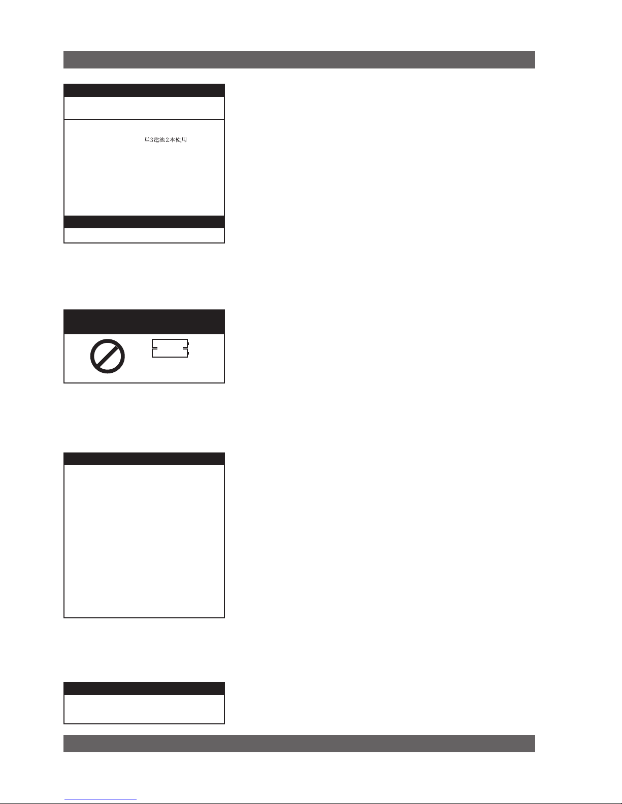
NEDA: 14A ANSI: 14A IEC: LR14
Alkaline batteries must be one of following types:
SW70-H1, SW65- & 75-T Transmitters
2 “AA” size (14.5x50.5mm,
• NiMH Rechargeable (Sabine part #: SWBAA2)
• Alkaline: NEDA 14A - ANSI 14A - IEC LR14
• Heavy Duty batteries (NOT recommended)
)
Acceptable Batteries for use with
Handheld & Beltpack Transmitters
IMPORTANT BATTERY INFORMATION
WARNING! DO NOT USE
Alkaline Rechargeable Batteries
Alkaline “AA”
Rechargeable
Batteries
Alkaline
Rechargeable
19
Sabine Smart Spectrum® Wireless
LIT-SWM6-7000-OG-EN-110203.indd
© 2011 Sabine, Inc.
4.2.4.2. Charging Your Batteries
Equipment Connections. Each SW65- & 75-T or SW-H Series transmitter comes equipped with an SWC-POWR Tireless Wireless™ plug-in
charger (see Fig. 4l). In addition, each SW-H comes with its own batterycharging mic clip (SWC70-CL). The SWC-POWR charger can be plugged
directly into either the transmitter or into the clip. A Sabine rechargeable
battery (SWBC1) will charge whenever the mic clip is connected to the
Sabine SWC-POWR charger and the handheld is properly placed within
the mic clip.
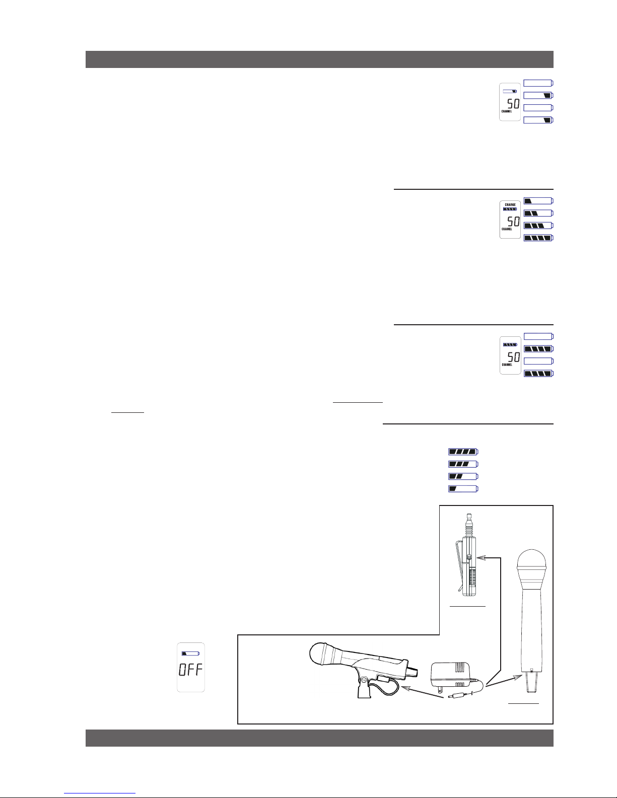
Charging Indicators. Much like your cell phone, the transmitters will let
you know the charging status of the battery. When the battery is charging, the battery meter will flash to indicate the relative level of the charge
— one, two, three or four elements will flash (see Fig. 4i).
Once the battery is fully charged, all four elements in the battery meter
will flash. This indicates that the charging circuit is no longer on (see Fig.
4j).
NOTE: The right-side indicator segment will flash for several minutes
when charging is first attempted (see Fig. 4h). The lower the battery
level, the longer this initial “testing/not charging” flashing sequence will
continue. During this time, the Tireless Wireless battery circuit is evaluating the suitability and charge status of the battery in place. When it has
completed its evaluation, it will either commence the progressive flashing
depicted in figure 4i (CHARGING), or continue to flash (TESTING/NOT
CHARGING). All segments flashing in unison signifies that the battery is
fully charged (see Fig. 4j).
These same indications will also be displayed on the receiver LCD, and
on the Remote Control Software screen.
NOTE: The Tireless Wireless battery charger will only charge NiMH
rechargeable batteries. If you place any other kind of battery in the
transmitter, and then attempt to charge it by connecting the charger, the
Tireless Wireless circuit will detect the type of battery and will not begin
charging. Again, the battery indicator on the transmitter will flash the
right-side element indicating testing/no charging (see Fig. 4h).
Battery Warnings. When the transmitter battery voltage drops below a
critical threshold, the battery icon (which normally displays the voltage
level) will begin to flash. This will occur on the transmitter and receiver
and is an indication that you need to replace the battery, or charge it by
placing the handheld mic in the charger clip. NOTE: Microphone will still
transmit audio when placed in clip. Alternatively, you can connect the
charger directly to the transmitter using the built-in charger jack located on
the side of the beltpack transmitter and near the antenna on the handheld
transmitter (see Fig. 4l). If the battery is not changed or recharged, the
transmitter will eventually turn off (see Fig. 4k).
Transmitter Operation
Fig. 4l: SWC-POWR plug-in charger for SW70 Series Transmitters & SWC70CL Mic Clip
Fig. 4h: T ES TI NG/NOT
CHARGING
Right-side battery indicator
segment will flash to indicate
that the battery is being
teste d. This occurs prior
to charging a NiMH battery and whenever a
non-rechargeable battery is placed on charge.
Charging is not occuring when indicator lights
in this fashion.
Fig. 4j: FULL CHARGE
Battery indicator segments
will flash in unison to indicate that the battery is fully
charged.
NOTE: Battery can be left
connected to the charger and will receive periodic maintenance charging.
Fig. 4i: CHARGING
Battery indicator segments
will flash progressively starting from the relative charge
state of the batter y. This
example depicts a fully discharged battery being charged. As the charge
progresses, left-side segments will remain visible as right side segments continue to flash,
until all segments are visible. At that point, all
segments will flash on and off in unison (see
Fig. 4j).
Fig. 4k: Battery CHARGE LEVEL displays
NOTE: When the battery has reached a
specific discharge level, the transmitter
will automatically tur n
off, and the transmitter LCD will display the
message at right.
Very Low (Flashing)
Very Used
Partially Used
Fully Charged
SW65/75T
SW70H1
SWC70CL
(Mic Clip for SW70H1)
20
Sabine Smart Spectrum® Wireless
© 2011 Sabine, Inc.
5. RECEIVER OPERATION
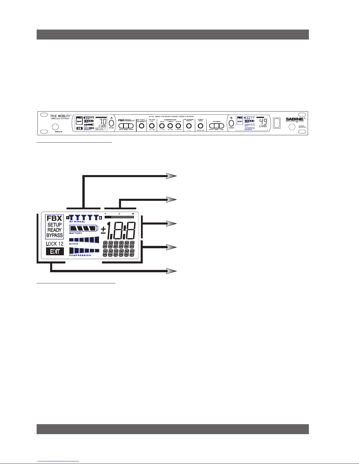
5.1. LCD Display.
The receiver LCD display is shown below (Fig. 5b). Two-channel receivers feature
two LCDs, one for each channel. The display provides a snapshot report of the
condition of your wireless channel, including battery status information sent from
the transmitter by telemetry.
The right two-thirds of the display primarily shows status information regarding
the condition of your receiver channel, as follows:
Receiver Operation
Fig. 5a: SW72-R (SW62-R) front panel
Fig. 5b: Receiver LCD Compete Display
Receiver LCD Status Bars
Relative Position Indicator
Function Value Display
Function Display Messages
FBX, Lock and Edit Status Indicators
 Loading...