

SABINE SWM4000 Series, Smart Spectrum SWM4000 Series Operating Manual

Operating Guide
SWM4000 Series


Quick Start Guide ........................................................................................................... 2
Components .................................................................................................................. 3
Receiver ......................................................................................................................... 4-5
Handheld Transmitter .................................................................................................... 6
Beltpack Transmitter ....................................................................................................... 7
Operating Instructions ................................................................................................... 8
Setting up your System .................................................................................................. 9
Appendix A Manual Programming ................................................................................. 10
Appendix B Frequencies and Groups ............................................................................ 11
Appendix C Rack-Mounting Receivers ........................................................................... 11
Appendix D Tips for Improving System Performance .................................................... 12
Appendix D Troubleshooting .......................................................................................... 12
Appendix E Specications .............................................................................................. 13
© 2010 Sabine, Inc.
1
Sabine SWM4000 Smart Spectrum® Wireless
LIT-SWM4000-OG-EN-100205.indd
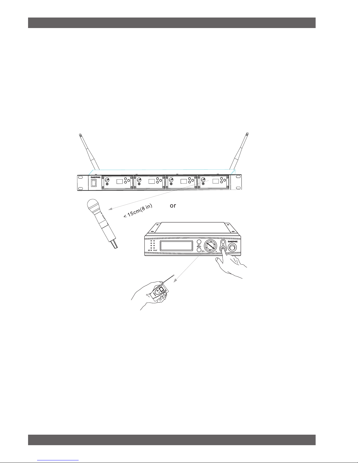
Quick Start Guide for SWM4000 WIRELESS SYSTEMS
Setting up the SWM4000 Receivers.
1. Plug the PSU power supply into the wall socket and receiver and power on the unit.
2. Push the MENU button until the words “Auto Select” appear in the LCD (SW40-RH). Or, the word “SCAN” for the SW40-RF
3. Push the SET button. The SW40-RH or SW40-RF will set itself to a clear channel and display the channel on the receiver LCD.
4. Turn on a transmitter (leave the other transmitters turned off). Aim the transmitter’s IR sensor about 8 inches from the receiver’s IR
scanner and press the receiver’s S.O. (SYNC) button for several seconds while the receiver programs the transmitter. When the group
and channel numbers on the transmitter matches the receiver, the system is ready to operate. The RF LED should be fully lit when you
are standing close.
Expose the IR port to the receiver, press S.O. (SYNC)
SW40-RF
SW40-RH
SW40-T
5. Speak, sing or play into the transmitter to adjust the volume control so that the A.F. LEDs generally light under normal performance
conditions. The volume should be adjusted so that the top A.F. LED only lights momentarily with the loudest inputs. You will hear a
harsh clipping sound if the top LED stays lit under normal levels.
6. Adjusting the squelch. The squelch controls the maximum distance between the transmitter and receiver. It is set to maximum range
at the factory and should be kept there in most cases.
For Multiple Systems
• Repeat steps 1 – 6 if you wish to add more systems. IMPORTANT: Make sure to keep the transmitters that have been set up
turned on so that new receivers will know those channels are busy.
• See Appendix A for manually selecting the frequencies of your system.
• Be sure that only one transmitter’s IR port is exposed when setting up a system.
Sabine SWM4000 Smart Spectrum® Wireless
© 2010 Sabine, Inc.
2
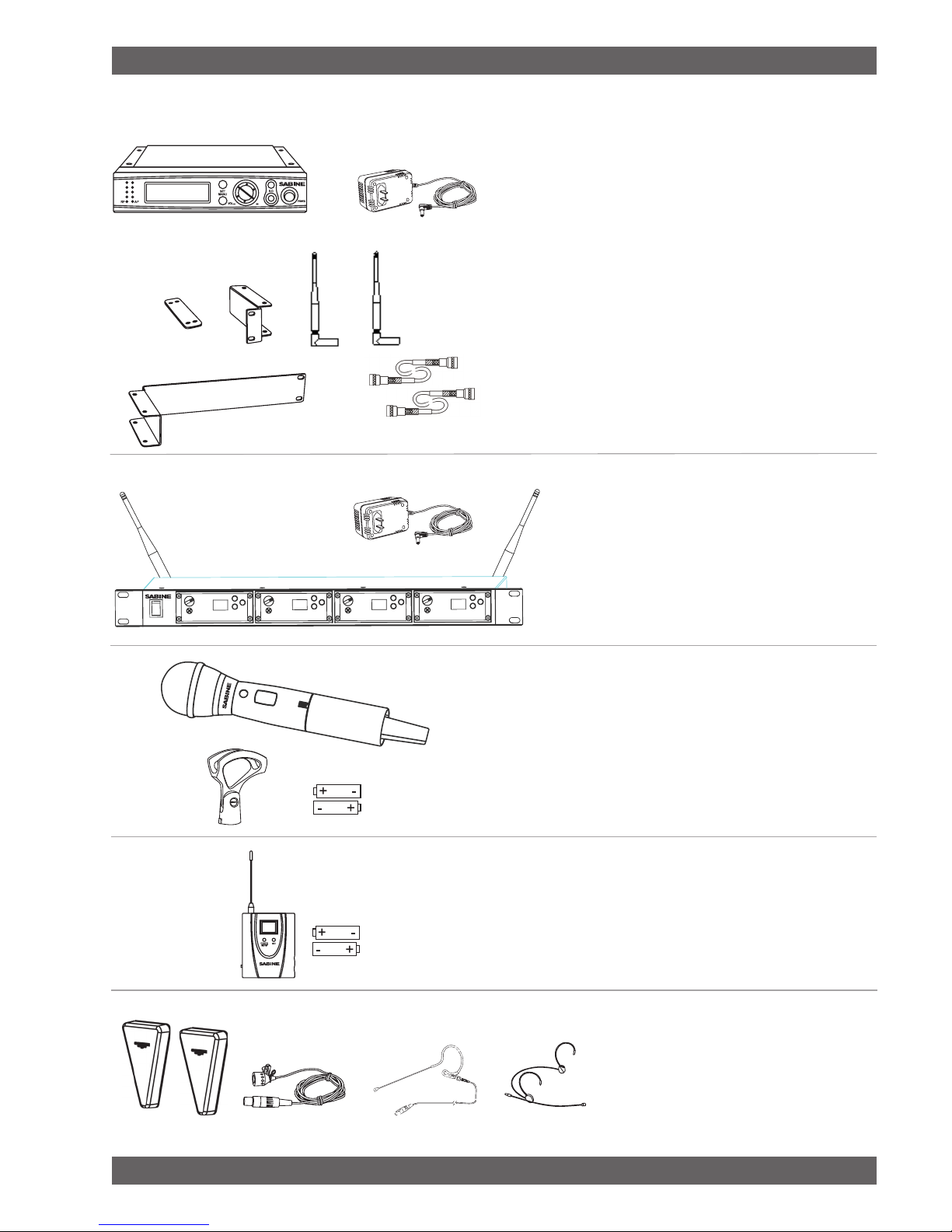
Components
SW40-RH Half-Rack receivers include:
Power Supply•
Dipole antennas (1 pair)•
Rack Mount kit:•
Short rack ear
Long rack ear
Link bar to mount a second SW40-RH receiver
8 rack screws
4 rack mount screws
Extension cables and connectors for front-mounting antennas•
1/4 inch patch cable (not shown)•
operating guide•
SW40-R modular receivers include:
Module Frame with 1, 2, 3 or 4 modules•
Dipole antennas (1 pair)•
Power Supply •
Operating guide•
SWASS-EXT 3
SW40-T
SWT31L-TA4
SWT74W-OSB-TA4 SWT74W-ODB-TA4
SW40-H Handheld transmitters include:
• Microphone and transmitter
• Mic holder
• AA batteries (1 pair)
SW40-T Beltpack transmitters include:
• Beltpack transmitter
• AA batteries (1 pair)
Optional:
• Extention antennas.
• lavalier microphone
• single-ear microphone
• double-ear microphone
See www.Sabine.com for details.
© 2010 Sabine, Inc.
3
Sabine SWM4000 Smart Spectrum® Wireless
LIT-SWM4000-OG-EN-100205.indd
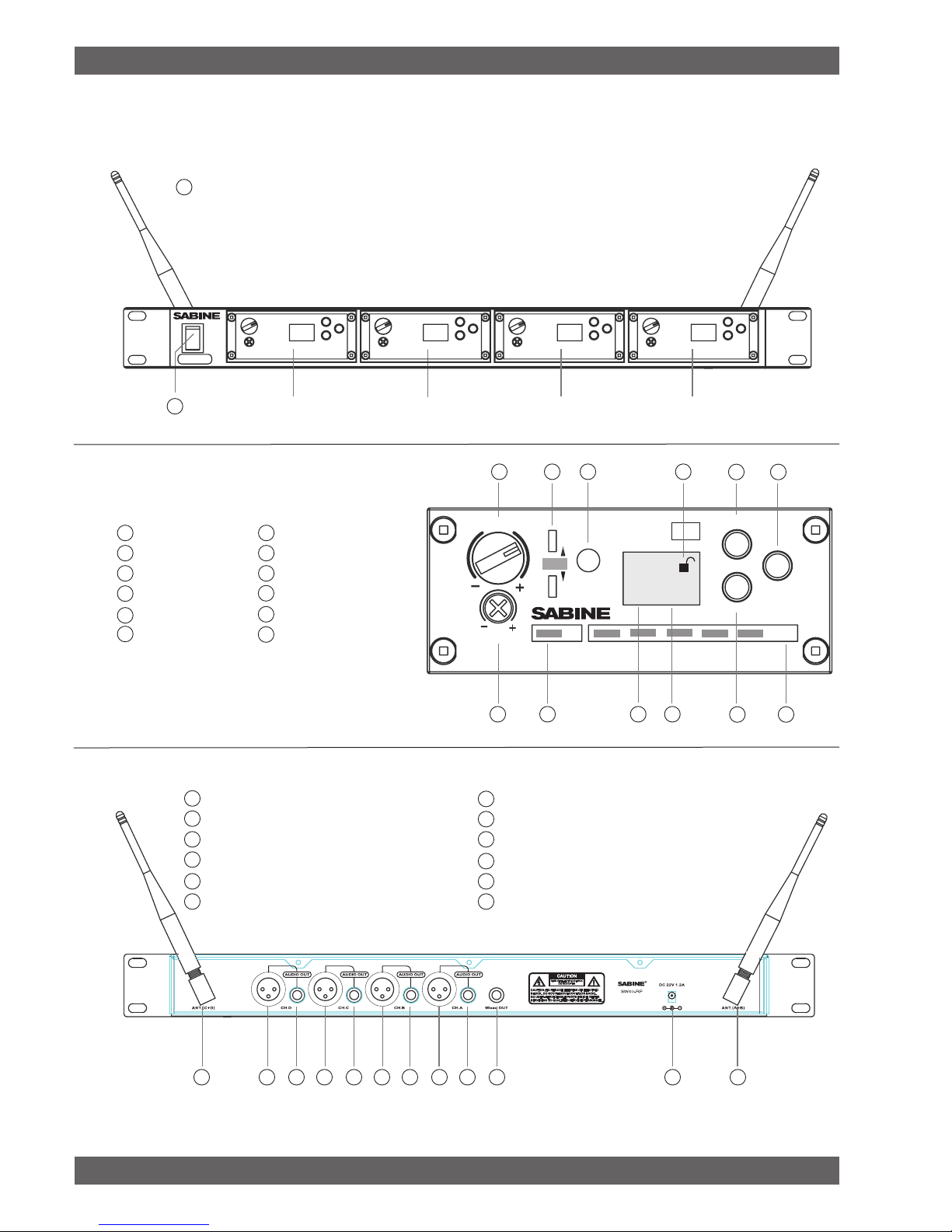
SW40-RF-Module Receiver Details
SW40-RM
VOL
A
B
ANT
S.Q.
I.R.
RF
AF
MENU
SYNC
SET
TRUE DIVERSITY
RECEIVER
UHF
GROUPCHANNEL
02 04
POWER
SW40-RF
Front Panel
R1
Power on/off
R1
Module Front
R2
Volume (Gain)
R3
Squelch
R4
RF signal
R5
Active antenna
R6
I.R. sensor
R7
Group selection
Back Panel
Module A
R8
Channel number
R9
Lock all controls
R10
Set
R11
Menu
R12
Sync
R13
Audio signal
R14
Antenna B
R15
XLR output jack for module D (balanced)
R16
1/4” jack output for module D (unbalanced)
R15
XLR output jack for module C (balanced)
R16
1/4” jack output for module C (unbalanced)
R15
XLR output jack for module B (balanced)
Module B Module C
R2
R3
R16
1/4” jack output for module B (unbalanced)
R15
XLR output jack for module A (balanced)
R16
1/4” jack output for module A (unbalanced)
R17
Mixed output for all modules (unbalanced)
R18
PSU power jack
R19
Antenna A
R5 R6
R4
R7 R8
Module D
R9
R10 R12
R11 R13
© 2010 Sabine, Inc.
Sabine SWM4000 Smart Spectrum® Wireless
R14 R15 R16 R16 R16 R16R15 R15 R15 R17 R18 R19
4
 Loading...