

Page 1
The two-channel POWER-Q gives you
two full racks of gear -- all in one!
CURVE
TURB -
Automatic Room Flattening EQ
Program Shaping EQ
FBX Feedback Exterminator
Parametric EQ
Real-Time Analyzer
Compressor/Limiter
Downward Expander/Gate
Digital Delay
Digital Delay
Program Memory
Automatic Room Flattening EQ
Program Shaping EQ
FBX Feedback Exterminator
Parametric EQ
Real-Time Analyzer
Compressor/Limiter
Downward Expander/Gate
Digital Delay
Digital Delay
Program Memory
Page 2
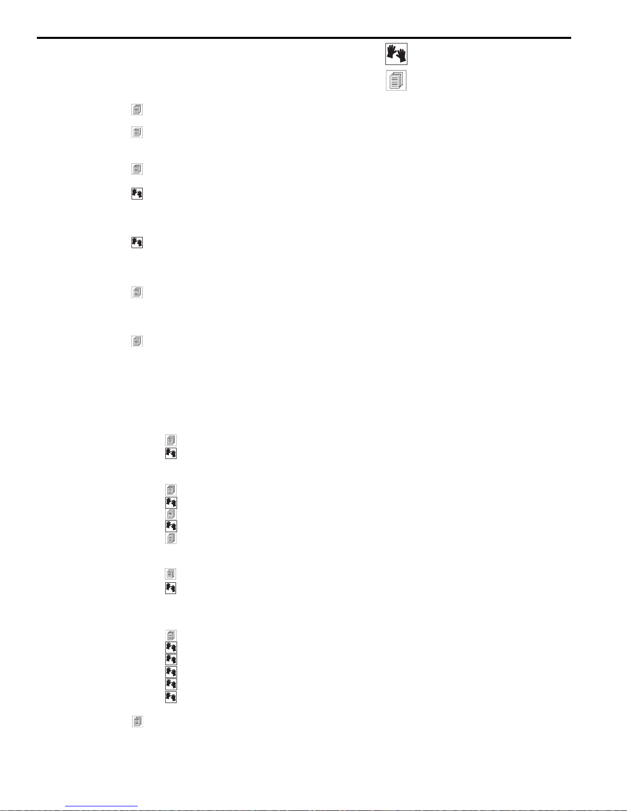
Table of Contents
1.0 Introduction..................................................................................................................4
2.0 Front and Back Panel Views and Controls...................................................................5
3.0 Block Diagram/Internal Signal Path .............................................................................6
4.0 Installation ...................................................................................................................7
5.0 Quick Start-up Reference ............................................................................................9
6.0 Overview and Philosophy ...........................................................................................10
7.0 Optimizing the Sound System and the Room with the POWER-Q: Five Steps ...........12
POWER-Q operating information
Background information
2.1 Main Menu windows (quick reference)
4.1 Where to install your POWER-Q in the sound system
4.2 Bypassing the POWER-Q
5.1 EQing an acoustic environment: Quick Instructions
5.2 Exterminating feedback: Quick instructions
6.1 Quest for loudness
6.2 Quest for clarity
7.1 Step One: The physical space
7.2 Step Two: Time alignment of speakers
7.3 Step Three: Setting the system and room to a “flat” response curve
7.4 Step Four: Tweaking the EQ
7.5 Step Five: FBX filters
8.0 Using the POWER-Q Digital Delay .............................................................................14
8.1 Digital delay applications and use
8.2 POWER-Q digital delay adjustments: Manual and automatic
9.0 Using the POWER-Q Automatic Room EQ ................................................................23
9.1 What is Automatic Room EQ?
9.2 How Automatic Room EQ works
9.3 Reference microphone choice
9.4 Reference microphone placement
9.5 POWER-Q controls for Automatic Room EQ
10.0 Using the POWER-Q Graphic Equalizer...................................................................29
10.1 Graphic equalizer applications
10.2 POWER-Q graphic EQ screens and options: Graphic EQ, Curve
Display , Reset Filters
1 1.0 Using the POWER-Q FBX/Parametric Equalizer ......................................................32
1 1.1 Types of filters: Fixed FBX, Dynamic FBX, and Parametric
1 1.2 FBX TURBO/Auto TURBO setup modes mode
11.3 POWER-Q FBX/parametric filter adjustments
1 1.4 Filter control menu: List Mode and Curve Mode
1 1.5 The “MORE” button for the FBX/parametric window
1 1.6 Preventing feedback in the event of equipment failure
12.0 Using the POWER-Q High and Low Pass Filters......................................................38
Page 3
13.0 Using the POWER-Q Real-Time Analyzer................................................................39
13.1 Using a real-time analyzer
13.2 POWER-Q RTA adjustments
13.3 Using the POWER-Q RTA and digital delay settings to minimize comb filters
13.4 Using the POWER-Q RTA during performance
14.0 Using the POWER-Q Compressor/Limiter................................................................42
14.1 Compressor/limiter applications and use
14.2 POWER-Q compressor/limiter adjustments
15.0 Using the POWER-Q Expander/Noise Gate.............................................................44
15.1 Expander/noise gate applications and use
15.2 POWER-Q expander/noise gate adjustments
16.0 Saving and Loading Stored Configurations...............................................................46
16.1 Recall and storage options and use
16.2 Saving EQ Settings: Room EQ and Program EQ
16.3 Using the POWER-Q stored configuration window
17.0 Global Parameters: Configuring Internal Default V alues..........................................48
18.0 Password.................................................................................................................50
19.0 POWER-Q Options ..................................................................................................51
20.0 Remote Control of the POWER-Q ............................................................................51
20.1 Computer Requirements
20.2 Installing SABINE POWER-Q Remote Software
20.3 Using SABINE POWER-Q Remote Software
20.4 POWER-Q Remote Software Guide
21.0 POWER-Q Digital I/O Option.......................................................................................60
22.0 Bypass Options
23.0 Using the ADF: A Pro’s Guide, with Ken Newman ....................................................62
24.0 Troubleshooting T ips ................................................................................................64
25.0 Engineering Specifications........................................................................................65
26.0 Cautions and Warranty .............................................................................................66
Operating Guide Version 8 -- for POWER-Q firmware v2.40
Special thanks to Hans Drobilitsch of Hans Drobilitsch Audio GmbH. (Austria) and
Andreas Schneider (Chief Sound Engineer, Austria Center V ienna) for their valuable
contributions to the design and implementation of the POWER-Q
.
Page 4
Section 1: Introduction
Section 1: Introduction
Congratulations and welcome to the new digital equalization and signal processing power of
the Sabine POWER-Q ADF-4000, two whole racks' worth of power in a single 2-U unit. Patch
the POWER-Q between the output of your mixer and the input to your crossover or power
amp, and you’re ready to harness the power of an arsenal of digital signal processing. (Note:
You can also use the POWER-Q in other configurations. See Section 4.1.)
The POWER-Q is truly remarkable because of its multi-tasking ability and ease of operation.
It's the latest breakthrough in the Sabine ADF Adaptive Digital Filter Workstation product line
and offers many of the features of the Sabine REAL-Q2 Real-Time Adaptive Equalizer - all in
one package.
The POWER-Q encompasses the following functions, all of which operate concurrently:
• Two separate, 2-channel, 31-band digital graphic equalizers
• Up to 12 additional filters per channel, configurable as any combination of:
• High and low-pass filters for each channel
• 2 channel fully adjustable compressor/limiter
• Full featured, filter-based RT A
• 2 channel digital delay for programmable time alignment of speakers by up to 83.2
mSec.
• 99 memory settings. Instant recall of all or selected parameters.
• Automatic Room EQ. Calibrate a system in any acoustic space to a flat response
curve automatically in just a few seconds.
• ClipGuard™ Adaptive Clip Level Control. This patented Sabine function
automatically prevents digital clipping and expands dynamic range to over 1 10dB.
• Optional remote control via RS-232 interface (for Windows™ computers)
• Optional Digital I/O: Allows user-selectable sample rate and input source.
• fully parametric filters
• fixed or dynamic automatic feedback control filters with Sabine’s patented
FBX Automatic Feedback Control technology
Y ou may quickly refer to the sections you need by scanning for the appropriate icons:
This manual is written to provide background information for implementing the POWER-Q’s
features in appropriate situations. These sections of the manual are denoted with the “BACKGROUND” icon.
Sections of the manual pertaining to operating the POWER-Q are indicated by the “HANDS
ON” icon.
Any information we think is essential is highlighted with an “IMPORTANT! READ THIS!” icon.
If you really can’t wait to get started using your POWER-Q immediately , refer to our “quick
start” section (Section 5). We do recommend you read the manual for a fuller understanding
and more complete utilization of the POWER-Q's features.
4
Page 5
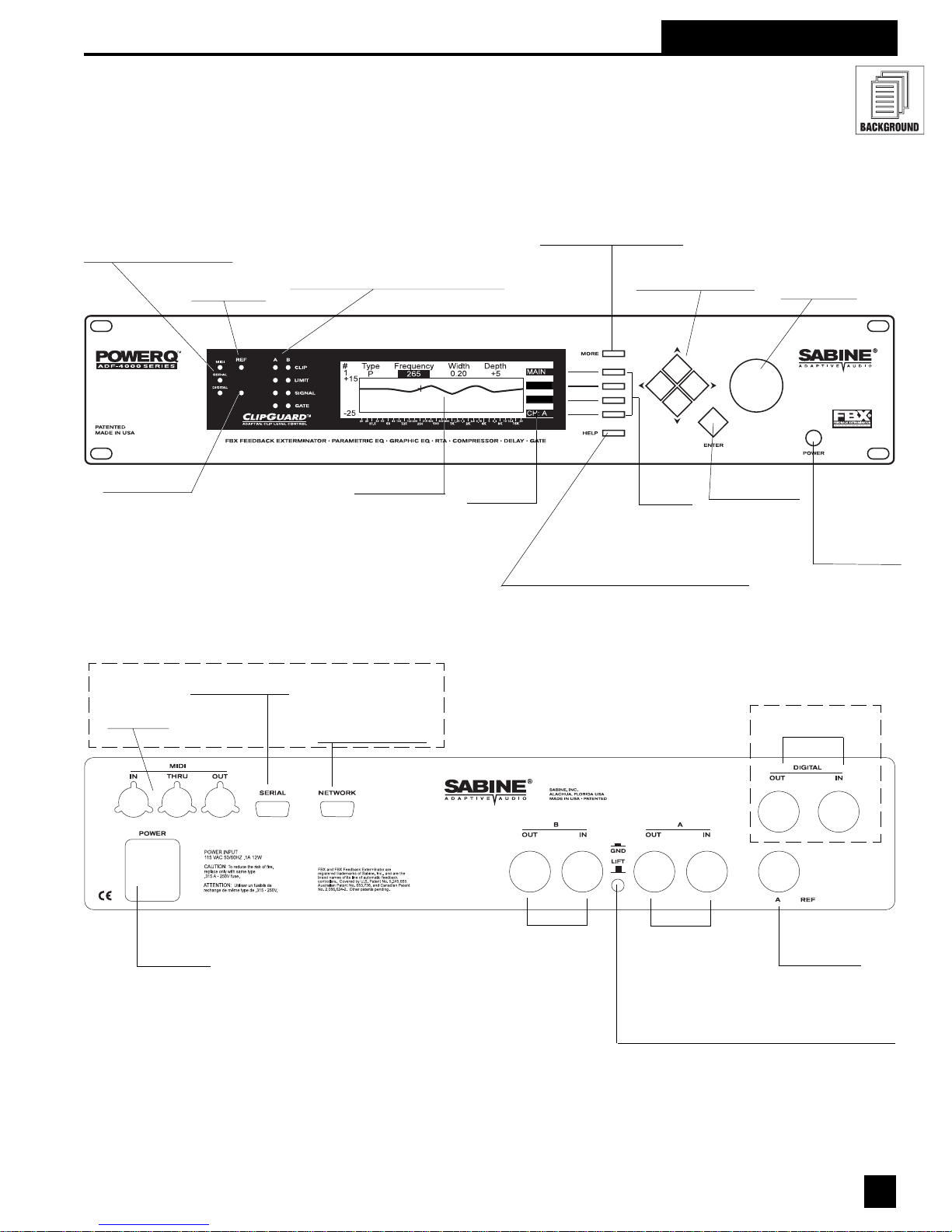
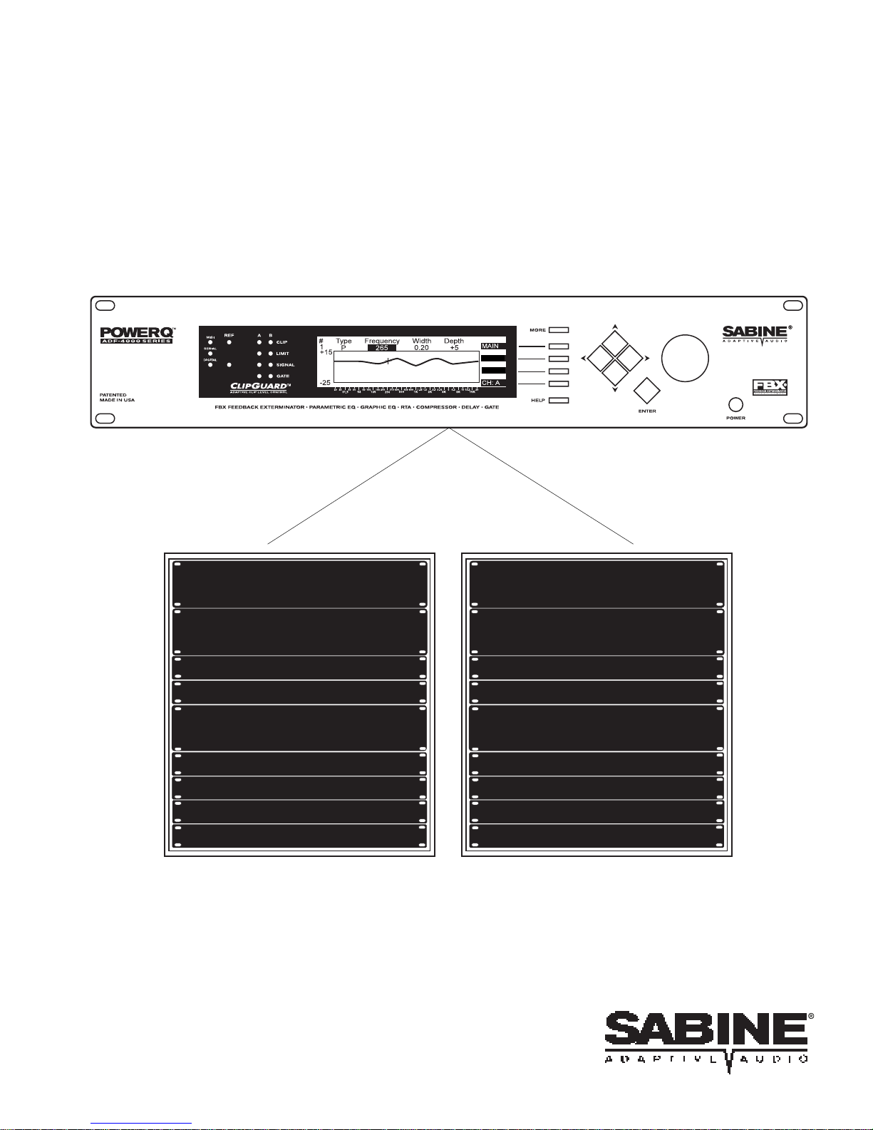
Section 2: Front & Back Panel Views & Controls
Fig. 1: POWER-Q Front Panel
Function Indicators for each channel
CLIP: CLIP LEVEL indicator lights when the input
Remote Control Indicators
MIDI: MIDI data
SERIAL: RS232 serial port data
DIGITAL: AES/EBU digital interface
*
Reference Mic
Clip Indicator
level is 3 dB below clipping level.
LIMIT: Indicates signal above limit or compressor
threshold.
SIGNAL:Lights when signal level is above -30 dBV
peak.
GATE: Indicates signal below gate or expander
threshold.
MORE Button chooses
additional POWER-Q menus
or soft key selections
CURVE
TURB -
Section 2: Controls
Up, Down, Left, Right
Cursor Movement Keys
Data Wheel
selects values
Reference Mic
Signal Indicator
Fig. 2: POWER-Q Back Panel
RS232 Remote
Control Connector
MIDI I/O
*
Connectors
Display Window
SERIAL REMOTE OPTION
RS232 POWER-Q
Network Connector
(for multiple POWER-Qs)
Soft Key
Menu Items
Soft Key
Selectors
Online Context-Sensitive HELP button
(When HELP screen is activated, "HELP" will
appear in lower right of display window. To escape
HELP screen, press HELP button again.)
ENTER Key
initiates action
Power On/Off
The POWER-Q will
automatically pass
signal through a
hard wire bypass
when the unit is
switched off.
DA-I/O OPTION
Digital Audio I/O
Connectors (XLR-3)
IEC-320/C14
AC Power
Connector
as of this publication, MIDI control of the POWER-Q is not yet implemented.
*
Channel B Input
and Output
(XLR-3)
Channel A Input
and Output (XLR-3)
Ground Lift Switch
(Differing ground potentials between or among interconnected
equipment racks may introduce hum or noise into the sound
system. The POWER-Q ground lift switch isolates the AC
ground from the chassis when in the extended position.)
Reference Mic
Input (XLR-3)
5
Page 6
Sections 2 & 3: Menus & Diagrams
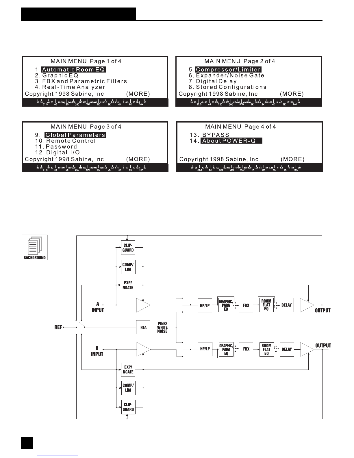
2.1 MAIN MENU WINDOWS (QUICK REFERENCE)
Fig. 3: Main Menu Items
Section 3: Block Diagram/Internal Signal Path
Fig. 4: POWER-Q
Internal Signal
Path
6
Page 7
Section 4: Installation
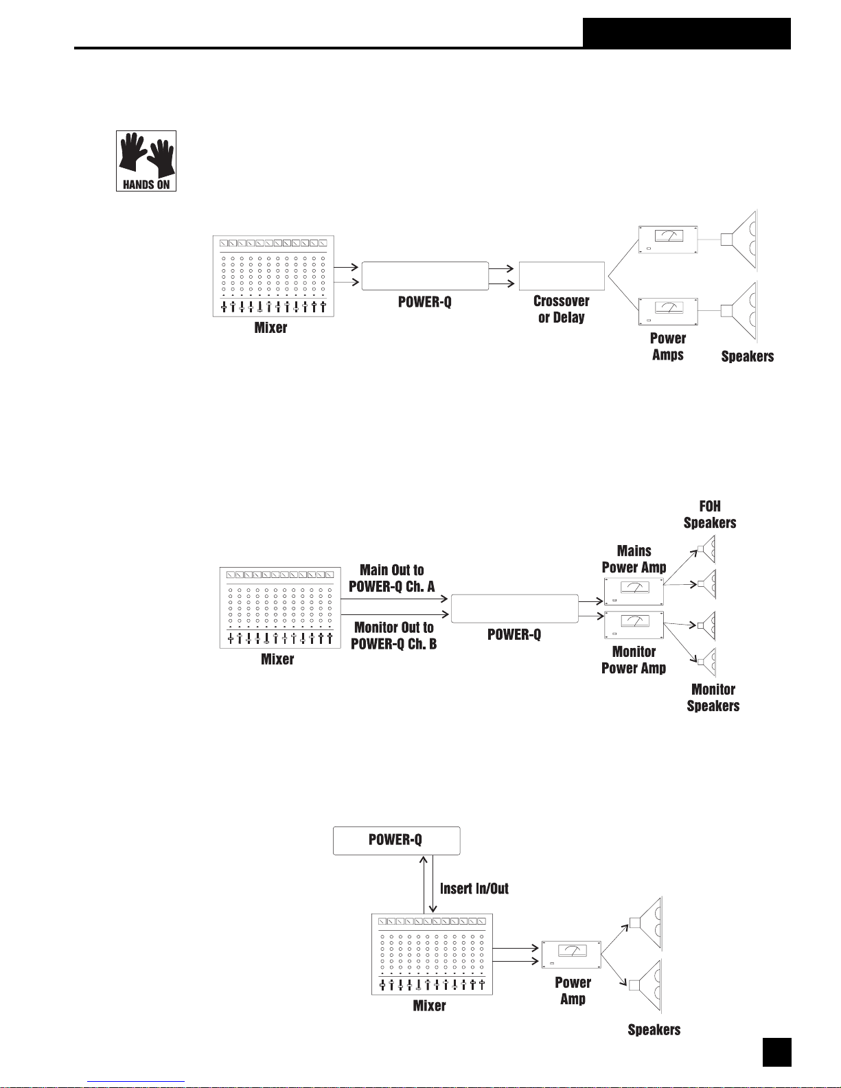
4.1 WHERE TO INSTALL YOUR POWER-Q IN THE SOUND SYSTEM. The most common placement of the
POWER-Q is between the output of a mixing console and the input to a power amplifier. If your
system requires a crossover or additional delays (such as the Sabine DQX-206), put the POWER-Q
in line after the mixer, but before those units. The configuration looks like this:
Fig. 5: Most common
setup
A variation of this setup might involve using the POWER-Q as a “dual mono” unit. Patch the main
output of your mixer into Channel A of the POWER-Q, and the monitor output into Channel B.
Then plug Channel A POWER-Q output into your main power amp, and Channel B POWER-Q
output into your monitor power amp. This will allow use of the POWER-Q as if it were two separate mono units. The configuration looks like this:
Section 4: Installation
Fig. 6: Using the
POWER-Q as a "dual
mono" unit
Fig. 7: Using the
POWER-Q at a mixer
insert point
The POWER-Q may also be used at a mixer insert point, either for a single input channel, or for a
group or bus insert point. This will dedicate all of the features of the POWER-Q to a pair of single
channel inputs on your mixer or to a subgroup of inputs (for example, all the drums in your mix).
The patching will look like this:
7
Page 8

Section 4: Installation
The reference microphone for the POWER-Q plugs in the back of the unit, into the jack labeled
“Ref A.” The “Ref B” jack is blank.
THE POWER-Q SHOULD NOT BE USED IN THE FOLLOWING CONFIGURATIONS:
·Do not plug a microphone directly into the channel A or B XLR input connections on the back
of the POWER-Q. These plugs are for balanced line level inputs, not microphones.
·Do not use the POWER-Q in an effects or auxiliary loop. Since such a patch is designed for
mixing processed (wet) and unprocessed (dry) signals together in a variable proportion, the
processing of the POWER-Q will be mixed with the unprocessed signal.
·Do not patch the output of any amplifier into any POWER-Q input. This will VOID your
warranty .
4.2 BYPASSING THE POWER-Q. The POWER-Q allows flexible options for bypassing all or part of its
internal processing. For more details please refer to Section 22.
A “quick bypass” can be accomplished simply by turning the unit off, which routes the input jack
directly to the output. However, please note two cautions when turning the POWER-Q on and/or
off:
1. If you turn the unit off, any suppressed feedback may suddenly reappear . As a precaution,
turn down the gain on your power amplifier.
2. When you turn the unit on, the unit will briefly be in bypass (for a few seconds) until the
processing is engaged. Suppressed feedback may occur during these few seconds. As a
precaution, keep your mixer and/or power amp turned down until the POWER-Q processing
engages.
8
Page 9

Section 5: Quick Start-Up Reference
If you want to get going in a hurry , first make sure your POWER-Q is correctly patched into your
system. There are two main tasks the POWER-Q will perform: equalizing the tonal balance of the
system and eliminating feedback.
5.1 EQing AN ACOUSTIC ENVIRONMENT: QUICK INSTRUCTIONS. There are three basic methods of equalizing a sound system with the POWER-Q: Automatic Room EQ, Real-Time Analysis, or by ear .
Automatic Room EQ. Make sure you have a reference mic positioned correctly and plugged
into “Ref A” on the back of the POWER-Q (very important for optimal results). Select #1 (“AUTOMA TIC ROOM EQ”) from the MAIN MENU. Follow the on-screen instructions. Your system will be
analyzed and the EQ adjustments in the POWER-Q will be made in 10 seconds per channel.
Real-Time Analysis. Alternatively, you may elect to play pink noise through your speakers and adjust the Graphic EQ to balance the frequency response. To do this, first make sure you
have a reference mic positioned correctly and plugged into “Ref A” on the back of the POWER-Q.
Then select #4 (“REAL-TIME ANAL YSIS”) from the MAIN MENU, press the “MORE” button and
turn on the pink noise independently for Channel A. Use the superimposed Graphic EQ sliders to
make additional adjustments. Repeat the procedure for Channel B.
Section 5: Start-Up
Equalizing By Ear. You won’t need to plug in a reference mic to EQ your system by ear.
Select soft key #2 (“GRAPHIC EQ”) from the MAIN MENU. This will display the graphic EQ
screen, one channel at a time (you may select which channel with a soft key). You may adjust
individual filters using a combination of left/right arrow keys and the data wheel.
In addition to or instead of the Graphic EQ, you may affect system equalization with the POWER-Q
parametric EQ. This is accessed by selecting MAIN MENU option #3, “FBX AND PARAMETRIC
FILTERS,” and playing an audio source through your sound system and the POWER-Q. Twelve
filters and a high and low pass filter are available for each channel. These filters are accessed using
the up/down arrow keys and can be set to parametric (“PARAM”) using the data wheel. The data
wheel and left/right arrows set the frequencies, filter widths, and filter depths of all filters. Any changes
made to the parametric filters will add to the overall EQ of the system, including graphic EQ settings.
5.2 EXTERMINATING FEEDBACK: QUICK INSTRUCTIONS.
1. Once your room is equalized to your liking (or you may elect not to equalize and proceed
directly to feedback control, though we don’t recommend this), set up your microphones and
acoustic instruments in the positions where they will be used.
2. If you are using your POWER-Q in a 2 channel system, turn the power amp to zero gain for one
channel. This will allow you to set FBX Filters for the other channel.
3. Set all other controls for your sound system at the settings that will be used for performance.
Select soft key #3 (“FBX AND P ARAMETRIC FILTERS”) from the MAIN MENU. The POWERQ defaults to seven fixed FBX, three dynamic FBX and two parametric filters, and has up to 12
total filters available for each channel. (This means that using parametric filters for room
equalization by changing these defaults reduces the number of FBX filters available for feedback control.)
4. Press the MORE button until you see “TURB-” on the screen. Press the adjacent soft key .
5. Highlight “Automatic Setup” with the arrow keys.
6. Raise the master gain of your mixer until feedback is just starting, then press ENTER on the
POWER-Q front panel.
7. The POWER-Q will automatically raise its output gain and set filters, until either all available
FBX filters are set, or until the first dynamic FBX filter is set. Then the POWER-Q will reduce
its output gain to its original level.
8. Repeat this procedure for the second channel, turning down the power amp for the channel just
filtered, and turning up the gain for the second channel.
(This is just one scenario for setting FBX filters. Please refer to Section 1 1 for additional details.)
9
Page 10

Section 6: Overview
Section 6: Overview & Philosophy
Live sound reinforcement can be a challenging business. Look what we have to deal with: The
guitar player turns up to 1 1 and still complains that she can’t hear herself. The podium speaker
points the mic at his sternum and mumbles, drowned out by the chatter of people eating dinner, in
a boxy hotel convention room. The rock singer asks for - no, DEMANDS - a monitor level loud
enough to hear over a drag race in a hurricane. The minister clips on the lavalier mic and wanders around while preaching, sometimes right past the speaker cabinet...
As an antidote to premature aging and undue stress, we at Sabine have dedicated ourselves to
simplifying the demands of live sound amplification by creating adaptive equipment that handles
some of the tedious (but important) mixing chores automatically . This allows sound engineers to
concentrate on making a mix sound good instead of dealing with acoustical problems!
The POWER-Q’s features are designed to help you achieve two important goals in sound reinforcement:
risk of sounding like a drill sergeant, let’s call this the desire to be LOUD and CLEAR.
6.1 QUEST FOR LOUDNESS. At least two bad things happen in the pursuit of loudness (putting aside
the deafness potential): feedback and lack of headroom.
getting more gain before feedback
, and
more clarity and definition in the sound
. At the
Let’s consider headroom first. The dynamic range of DSP is limited by the word length of an
individual datum: The more bits in a word, the greater the dynamic range. The POWER-Q offers
24 bit resolution and a dynamic range spec of >1 10 dB (with ClipGuard™). Plus, our ClipGuard™
Adaptive Clip Level Control system is designed to make it all but impossible for our units to clip
digitally; so if you’re hearing distortion in your system, it’s not likely coming from your POWER-Q,
because we’ve taken steps to prevent that. (Note: Make sure the FBX TURBO setup mode is off
before your program begins; see section 1 1.2.) Likewise, the compressor/limiter built into the
POWER-Q will raise the average gain level of your mix while protecting your speakers from hot
shot sound engineers whose goal in life is to explore the extremes of speaker cone flexion. All of
these functions are designed to maximize your gain without distortion.
Maximizing gain would be a far simpler matter if it weren’t for the problem created by adding gain
to a microphone in the presence of a speaker, which in turn reproduces the mic’ s sound, with the
mic in turn amplifying its own input, and so on. At some point, at least one frequency will regenerate. This is techno-speak for that dreadful ringing sound commonly known as feedback. The
nature and severity of the feedback will depend on the sound system and the acoustical environment, but feedback generally will occur before you reach the limits of your potential amplification.
This means that the most likely volume limitation of your sound system is not the power of your
amplifiers or the size of your speakers, but the threshold of feedback.
Enter the Sabine FBX. In the pre-FBX dark ages, feedback was often controlled by passing a mix
through a graphic equalizer and pulling out frequencies as close as possible to the ringing feedback. While this technique can reduce feedback, it also reduces the sound quality of the overall
mix. The one octave-wide filters of a third-octave equalizer (you read that right—the filters are
usually an octave wide, spaced on overlapping third-octave centers) are far too clumsy and
inaccurate to target feedback specifically . You don’t shoot a mosquito with a shotgun or do brain
surgery with hockey gloves. Shotguns, hockey gloves and graphic equalizers are valuable tools,
but only in the right applications. A graphic EQ is great to shape the overall sound of your mix
(and that’s why we’ve loaded your POWER-Q with two), but when you use it to control feedback
by pulling down EQ sliders, you’re also pulling out a big chunk of audio that is NOT feedback.
An FBX filter automatically detects feedback within a 1Hz resolution, places a tenth-octave wide
filter on it, and pulls down the level only as far as necessary to get rid of the feedback at a given
gain level. It is far more accurate in identifying and eliminating feedback and far less destructive
to your sound than even the best graphic equalizer. Plus it finds the feedback automatically in a
fraction of a second. You’d need to drink A LOT of coffee to react that quickly .
10
Page 11

Section 6: Overview
The POWER-Q provides up to 12 feedback filters per channel, thus allowing you to excel in your
quest for loudness without compromising your second, equally important goal: QUEST FOR
CLARITY.
6.2 QUEST FOR CLARITY. Clarity in the sound coming out of your speakers is a result of a myriad of
considerations: the quality of the components you’re using, the skill you and others demonstrate
in setting up and operating the system, and the all-important acoustic properties of the room in
which you’re operating your system.
Now, it’ s no secret that some architects skipped class the day of the 20 minute lecture on room
acoustics, which is why so many rock concerts take place in basketball arenas and live sound
people sport premature gray hair. Standing waves, flutter echoes, boominess...the list of problems is as big as a lead singer’s ego. (Our congratulations to those architects who DO pay
attention to room acoustics.)
The good news is that in addition to all the graphic, parametric, and FBX control in your POWER-Q,
you are also the proud possessor of a full-blown Real-Time Analyzer. Y ou can generate pink noise
to help determine the frequency response curve of the surrounding acoustic space and compensate
for its peaks and valleys with your EQ controls, while viewing a graphic display of the results in real
time.
If you’d rather use your time to set up mics, patch in the rest of your gear or take a break, the
POWER-Q Automatic Room EQ feature will analyze the room for you and optimize your system
EQ to the response curve you specify . At the next venue, you can do a quick room analysis (in
less than a minute), then you can recall the memory of all your other EQ settings and every other
parameter previously set on the POWER-Q. You’ll be done before the guitarist finishes tuning
(unless he uses a Sabine tuner, in which case it might be a tie).
You can also use the POWER-Q for clearer sound by time aligning speaker stacks with our built-in
digital delay . You can delay sound in one set of speakers by as much as 83.2 milliseconds (with
20 microsecond resolution) to allow sound to reach listeners’ ears at the same time. This improves the phase consistency of the program, greatly enhances intelligibility , and synchronizes the
perceived sound origination point so the directional cues from your ears match the visual cues
from your eyes.
In conclusion, the POWER-Q is your friendly rack of goodies conveniently condensed to a 2U box.
It will automatically align your speakers, tune your system to any room, automatically detect and
eliminate feedback before and DURING performance, compress your mix bus, and remember
your setup for a given artist or application. Sorry , it doesn’t make cof fee, but with everything the
POWER-Q does for you, you’ll have plenty of time to make it yourself.
11
Page 12

Section 7: Five Steps
Section 7: Optimizing The Sound System And The Room With
The POWER-Q: Five Steps
Remember, our quest is to amplify sound in a room to a desirable level without creating feedback
and distortion or sacrificing clarity. T o make the most of a sound system in a particular acoustical
environment, you will need to follow five simple steps:
1. Optimize the physical arrangement of your stage setup, speaker placement, and room
acoustics;
2. Time align your speaker stacks so that sound traveling from displaced speakers (and from
sound sources on stage) arrives at a designated reference position at the same time and/
or provides audio cues consistent with visuals;
3. “Flatten” the frequency response of your sound system in the acoustical environment so all
frequencies are heard in equal proportion at the reference position;
4. Adjust the equalization of the system to your personal preference or the requirements of a
particular application or performer (the POWER-Q will remember these settings and load
them from memory);
5. Apply FBX filters to live microphones to increase gain before feedback and insure maxi-
mum clarity , volume and microphone mobility.
The POWER-Q is amazingly useful for realizing steps 2 through 5 (see sections 8, 9, 10, 1 1, 12
and 13). Here are some suggestions for implementing all five steps.
7.1 STEP ONE: THE PHYSICAL SPACE. Unfortunately, the POWER-Q cannot physically rearrange your
stage setup or dampen reflective surfaces in your room. Y ou may not be able to build a bass trap
in a boomy room, find enough stage space to set the front-of-house speaker cabinets far enough
in front of the mic line to avoid howling feedback, or convince a night club owner to carpet the
dance floor. Ideally, a room with nonparallel, non-reflective surfaces that is large enough to
accommodate a full wave length (30 feet+) low bass frequency will provide you with fewer resonance points, a more evenly balanced room curve and less feedback. This acoustic ideal is
seldom found in the real world, so you should make the best of the situation with careful speaker
and microphone placement. To go beyond the limitations inherent in a less-than-desirable acoustical space, you’ll have to call in the artillery (electronics and equalization) to optimize your sound
system. This is why a device like the POWER-Q is worth every cent (and then some) of its very
reasonable price.
7.2 STEP TWO: TIME ALIGNMENT OF SPEAKERS. Compared to light or electronic signals, sound
travels very slowly . Sound traveling across a night club or concert hall, or from speakers at the
front of the stage to speakers half way to the back of the hall, is slow enough to often warrant
speaker time alignment with a digital delay . The sound emanating from a speaker farther away
from the listener is delayed relative to speakers close to the listener. The sound traveling to the
listeners’ ears from stage speakers takes longer to get there than the sound from the closer
speakers because most of the path for the latter is electrical. The correction is designed to allow
the sound from both sets of speakers to arrive at the listening position at the same time. (Obviously , in a situation where there is only a left and right front of house speaker stack, time alignment may be less of an issue. See Section 8 for a full discussion of these issues.)
The POWER-Q allows you to delay each output by up to 83.2 milliseconds. The delay time for each
channel can be set independently. For more details about setting the delay in your POWER-Q
output, refer to section 8.2. For more demanding delay applications involving up to six separate
outputs, automatic calculation of delay times and air temperature compensation, use the Sabine
DQX-206 delay/equalizer/limiter.
7.3 STEP THREE: SETTING THE SYSTEM AND THE ROOM TO A FLAT RESPONSE CURVE. Once the system
is in place and the speakers are time aligned, you are ready to even out (make equal, or “equalize”) the frequency response of the system in the room. This typically is done with broad filters,
such as the octave-wide filters of a 31-band graphic equalizer. Graphic EQ filters are spaced on
12
Page 13

Section 7: Five Steps
third-octave centers, but are typically an octave wide, overlapping across adjacent filter controls.
You can vary the width of the POWER-Q’s filters by accessing the “GLOBAL PARAMETERS”
option on the MAIN MENU (see Section 17).
The POWER-Q excels at the task of room equalization, offering both automatic and manual
frequency response adjustment. In the Automatic Room EQ mode (see section 9), a reference
microphone (with a reasonably flat frequency response) is placed at your choice of listening
positions in the acoustical environment. The POWER-Q automatically plays a short burst of pink
noise, and measures the energy across the audible spectrum as heard at the reference mic. The
POWER-Q then makes automatic adjustments to produce as flat a response as possible at the
reference position. Y ou can make additional EQ adjustments (parametric and/or graphic) after
Automatic Room EQ, to tweak your system response by ear. The entire Automatic Room EQ
process takes less than a minute for both channels of the POWER-Q.
Alternatively , you may choose to equalize your system by playing pink noise over the loudspeakers
and observing the REAL-TIME ANAL YSIS of the propagated energy across frequencies as heard
by the reference microphone (see Section 13). You must then manually adjust the equalization
faders of the POWER-Q’s graphic equalizer section to produce the desired frequency response.
Note that the POWER-Q allows you to see both your equalization faders and the RTA response
the same window,
while you make adjustments.
which spares you the cumbersome task of scrolling from one window to another
in
7.4 STEP FOUR: TWEAKING THE EQ. Once the room is flat, you may want to customize the room
equalization to meet your own personal tastes or to match the entertainers' performance style.
You may do this either by making further adjustments with a second graphic equalizer (see
Section 10) or by inserting up to 12 parametric filters per channel for very precise adjustment (see
Section 1 1). These filters can be added in list (tabular) form or drawn as a response curve using
the data wheel. Once you have room and system tweaked to your ideal, you can save and name
up to 99 settings for future quick recall (Section 16).
7.5 STEP FIVE: FBX FILTERS. In live sound reinforcement, the true limitation for system loudness is
not usually the wattage of the amplifiers, the headroom of the mixer or the power handling maximum of the speakers. Before the system clips, you will almost certainly encounter feedback. And
for eliminating feedback, there is no better system than the Sabine FBX Feedback Exterminator.
Once the sound system is properly equalized, the narrow filters of the FBX will go a long way
towards increasing loudness without feedback. Placing the FBX filters in line WITHOUT first
using a graphic equalizer to reduce broad resonant room frequencies may produce several narrow
FBX filters clustered together closely at a point. This means you will quickly exhaust available FBX
filters trying to do a job better suited to a wider filter (i.e., a graphic EQ fader), you’ll reduce the
amount of potential increased loudness, and you won't get the maximum benefit of FBX.
The POWER-Q is the most complete system on the market that allows this much control over the
steps to maximize clarity and gain in any acoustical environment, using any sound system.
13
Page 14

Section 8: Digital Delay
Section 8: Using the POWER-Q Digital Delay
8.1 DIGITAL DELAY APPLICATIONS AND USE. This section goes beyond the typical operating guide that
only explains the front and back panel adjustments of a piece of equipment. Instead, we discuss
the basic acoustical concepts needed to get the most out of the use of digital delay in sound
systems. If you are familiar with these principles, feel free to skip ahead. Some principles may
require additional delay channels and options available with the Sabine DQX-206.
Why Digital Delays? The most intelligible sound occurs when two people speak face to face.
The sound is loud and dry , and the direction of the sound aligns with the speaker. The most
intelligible sound systems are the ones that come closest to emulating face to face communication. If this is your goal, a digital delay is essential to your sound system.
There are three distinct applications for digital delays. The first and most important is synchroni-
zation of the loudspeakers to control excess reverberation and echo. Second, digital delays
help control comb filter distortion, and finally, digital delays are useful for aligning the acous-
tic image so the direction of the sound seems to be coming from the performer rather than from
the loudspeaker.
Loudspeaker Synchronization
Sound travels at about 1,130 feet per second in air, or about 1 foot per millisecond. On the other
hand, electronic signals travel almost one million times faster through your sound system to the
loudspeakers. The main task for digital delays is to synchronize multiple loudspeakers so the
sound traveling different distances arrives at the listener’s ears at about the same time. Synchronizing the loudspeakers reduces reverberation and echoes for improved intelligibility.
How to Synchronize Your Signals
There are several powerful tools available for precisely measuring the time a loudspeaker signal
takes to arrive at a certain point in the audience. Most of these tools are very sophisticated and
tend to be quite expensive. Fortunately, simpler tools are sufficient for most applications.
In the 1930’s, engineers synchronized the low and high frequency speakers in movie theaters by
feeding a sharp click through the system. They moved the speakers until they could only hear a
single sharp click coming from both speakers. You can use this same method with a common
child’s toy called a clicker. Pressing the thin metal strip makes a loud sharp click. A clicker is
especially useful when synchronizing the direct sound from the performer with the sound from the
loudspeakers.
Alternatively, you can use a phase checker especially for synchronizing the signals of two loudspeakers (either LF and HF or two full range systems) since most of the phase checkers include a
click generator and receiver. Phase checkers are quite affordable and have other uses besides
synchronization.
Processing (or Group) Delays
Converting signals back and forth from the analog to digital domain always delays the signal a
little. These conversion delays are often called processing (or group) delays, and usually range
between 0.9 and 5 milliseconds. You will notice that Sabine delays always display the processing
delay as the smallest possible delay value. For the POWER-Q, the processing delay is 1.38
milliseconds. You can bypass the unit for 0 seconds delay.
Not all manufacturers acknowledge processing delays in their specifications, but you
them into account when synchronizing your system. Make sure all digital equipment is on and not
bypassed when synchronizing. Also, be careful to make an appropriate adjustment in your delay
lines if you later add any type of digital equipment to the system.
14
must
take
Page 15
Section 8: Digital Delay
Center Cluster Speakers
Center cluster speakers offer several advantages over systems that have speakers mounted on
the sides. The most obvious advantage is that the distance to the closest and most distant
locations in the audience is often almost equal, so most listeners hear about the same level.
Center clusters also offer two other advantages regarding visual imaging.
Studies have shown that people can detect even small horizontal changes in the direction of a
sound source, but vertical shifts are much less noticeable. This suggests that the sound from
center-cluster speakers is more likely to be visually aligned with the performer than loudspeakers
placed on each side of the stage.
All those in the audience who are closer to the performer than the center cluster will hear the
direct sound from the performer before they hear the sound from the loudspeakers. This makes
the sound seem to come from the performer, not the loudspeakers. (See the Precedence Effect
below.)
Comb Filter Distortion
Many who took high school science may remember ripple tank experiments where waves are
generated from two separate point sources. The waves from each source combine to form visible
interference patterns. In some places the wave crests and troughs are in phase so they combined
to make a larger wave. In other places the crests are out of phase, so the crest of one wave
source is canceled by the trough of the other. Ripple tank experiments show the interference
patterns are strongest when the amplitudes of the waves from each source are equal.
A similar interference occurs in sound systems when a signal is delayed and mixed back into the
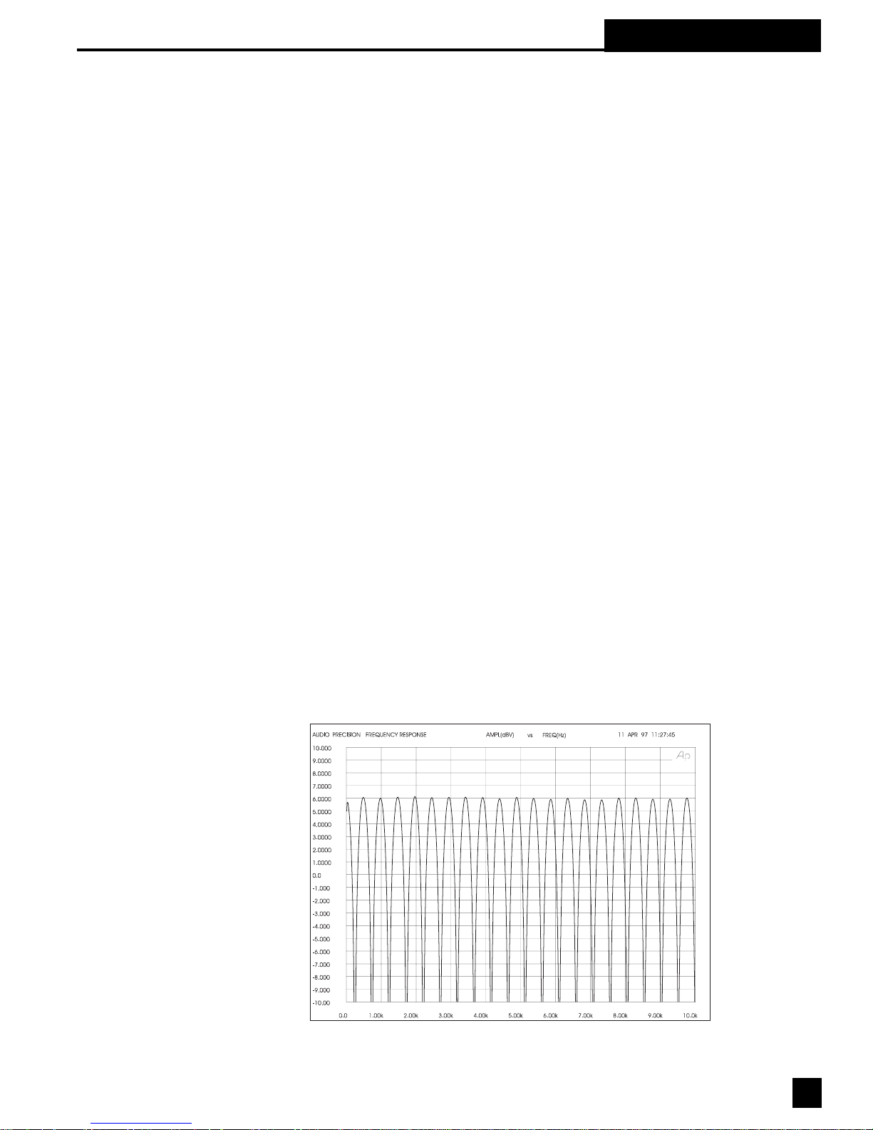
original signal. These interference patterns are called COMB FILTERS because their frequency
response plots look like the teeth of a comb (see Figs. 8 & 9). There are a number of common
situations that cause comb filters. For example, when the program is played through two loudspeakers, the loudspeaker that is farther away interferes with the closer loudspeaker. Comb
filters are also created when a performer is picked up by two microphones, one closer than the
other. You even introduce comb filters by mixing digital effects back into the “dry” signal at the
mixer’s effects loop.
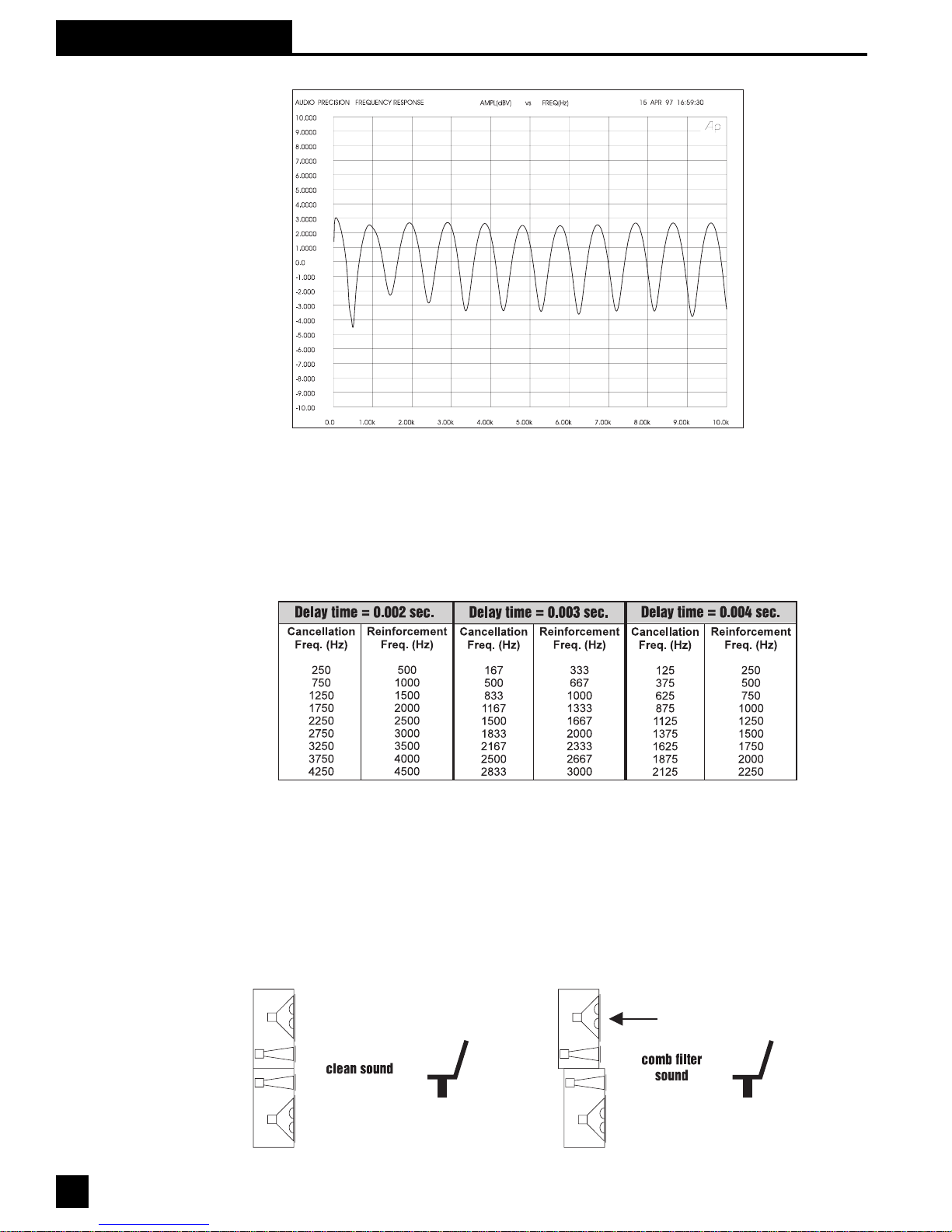
Fig. 8: COMB FILTERS. Input
signal mixed with a 2 msec.
delayed signal. (Both signals
have the same amplitude.
Max. filter gain is +6dB, and
max. depth is -4.)
15
Page 16
Section 8: Digital Delay
Fig. 9: COMB FILTERS. Input
signal mixed with a 2 msec.
delayed signal. (Delayed
signal has 10dB less amplitude. Max. filter gain is
+2.5dB, and max. depth is -3.)
Reducing the amplitude of the
delayed signal reduces the
comb filters' effect.
Calculating Comb Filter Frequencies
The frequencies of the reinforcements and cancellations depend on the delay time (the time
difference between the arrival time of the original signal and the delayed signal). The frequency of
the first cancellation occurs at 1/(2t) Hz, where t = the delay time in seconds. The cancellations
are separated by (1/ t) Hz. Fig. 11 shows how the comb filters change with the delay time.
Fig. 10: Comb filters get closer
as delay time increases.
Comb Filter Amplitude
If the original signal and the delayed signal are the same amplitude, the reinforced frequencies
increase in amplitude by 6 dB, while the out-of-phase frequencies cancel completely to -4 dB.
Comb filters cause a lot of problems. The frequencies that are reinforced are prone to excite
feedback, while the out-of-phase cancellations make the program sound thin and over equalized.
Try this simple experiment to hear what comb filters do to your sound.
Fig. 11: Comb filters noticeably affect your sound.
16
Page 17
Section 8: Digital Delay
Stack two identical full-range loudspeakers as shown in Fig. 12. Carefully align the HF horns and
wire the speakers in mono. Stand in front while listening to your favorite full-spectrum CD. Ask a
friend to move the top speaker slowly away from you. The degradation in sound quality you hear
is caused by comb filters. The experiment is most dramatic when you use good quality speakers.
Correcting Comb Filters
Comb filters are inevitable to some degree in every live sound system, and they cannot be
corrected with equalization. Fortunately, most comb filter problems can be reduced to a
minimum by synchronizing the signals and reducing the amplitude of the delayed signal. The
examples below show several practical applications.
The Precedence Effect: Aligning the Acoustic Image
Helmut Haas published a study in 1951 describing a series of experiments that demonstrated how
people perceive delayed signals and echoes. In his experiments, a listener was positioned
between two speakers placed 3 meters away; one was placed 45 degrees to the right and the
other was placed 45 degrees to the left. When the same program was played through both
speakers simultaneously, the listener perceived the acoustic image (the direction from which the
sound seemed to be coming) centered between the speakers.
When Haas delayed the signal going to one of the speakers by somewhere between 5 to 35
milliseconds, the listener perceived a shift in the acoustic image to the speaker heard first. While
the delayed speaker did not contribute to the apparent direction of the sound, it did make the
program seem louder and “fuller.”
Haas showed that you must increase the loudness of the delayed signal by about 8 to 10 dB
(twice the perceived loudness) in order for the acoustic image to move back to the original center
position. Increasing the loudness more than this, or increasing the delay somewhat more than 35
milliseconds, makes the delayed signal sound like an echo.
The phenomenon describing how the acoustic image follows the signal we hear first is called the
Precedence Effect. The phenomenon that makes two distinct sounds heard less than 35 msec.
apart seem like only one sound is call the Haas Effect. However, the terms are often used
interchangeably in the sound industry.
THREE APPLICATIONS FOR DIGITAL DELAYS
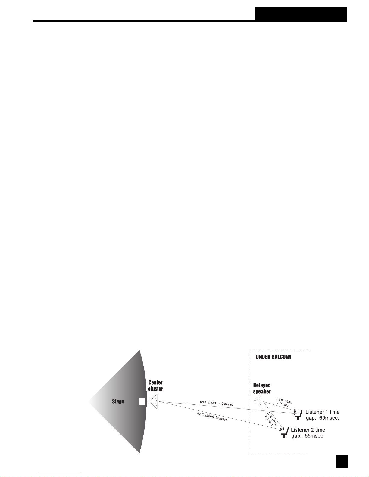
APPLICATION I: Under-The-Balcony Speakers
Fig. 12: Overhead view of
under-balcony application.
17
Page 18
Section 8: Digital Delay
Fig. 12 shows a typical situation where the performer is amplified by a center cluster hanging
above the stage. Almost everybody in the audience will enjoy good sound, except those seated in
the shadow of the balcony. So we add an under-balcony speaker to fill in the shadow.
Now we have sufficient volume under the balcony, but the sound from the two speakers arrives at
the listener’s ears some 55 to 69 milliseconds apart. The two signals, along with their echoes,
result in an unintelligible cacophony. We must delay the sound from the under-balcony speaker to
synchronize the signals. Do we set the POWER-Q delay to 55 or 69 milliseconds? Obviously, the
geometry will not allow us to exactly synchronize every location under the balcony; we have to
compromise.
First, consider the program type. For spoken word programs, you will produce the best intelligibility if the signals from the under-balcony speakers arrive within 10 msec. of the signals from the
center cluster. Therefore we should set the delay to 65-69 msec. You can allow a little more
reverberation for programs that are mostly music.
Next, we must eliminate comb filter distortion. Find the axis where the levels of the center cluster
and under-balcony speaker are equal. (See "Comb Filter Distortion," p.15.) You can use the
POWER-Q to precisely synchronize the speakers along this axis to eliminate the most severe
comb filters. Comb filters off the equal-level axis are much less of a problem since a louder signal
is not affected very much by a weaker signal.
Finally, you can experiment with adding 5 to 10 milliseconds delay to both sets of speakers to
enhance the Precedence Effect for the audience seated near the performer.
In the final analysis, every setting is a compromise, and your ear has to be the final judge. Check
the sound in several different locations throughout the auditorium and correct the most severe
irregularities.
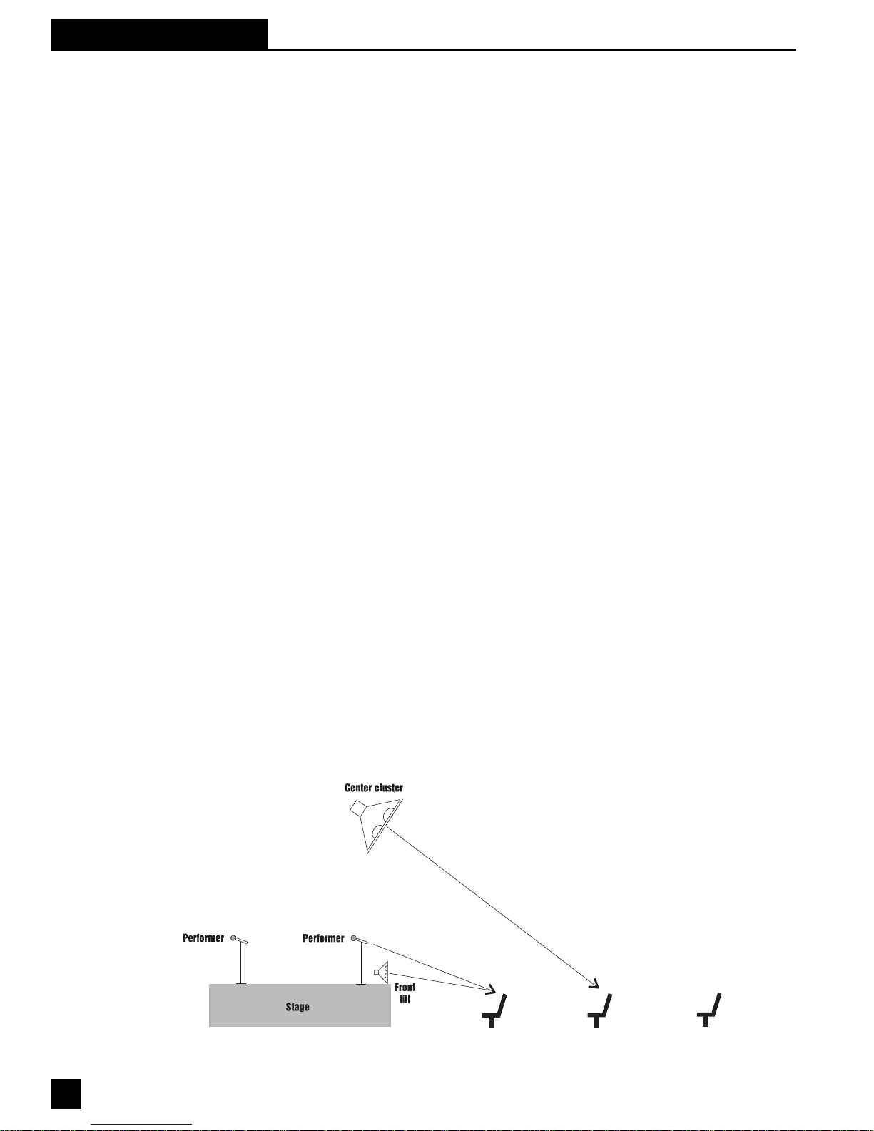
Application II: Center Cluster with Front Fills
Fig. 13 below describes a typical application that has a stage with a microphone, a center cluster
above the stage, and front fills in front of the stage. There must be thousands of installations
throughout the world like this that "get by" without digital delays. But with the POWER-Q, you can
improve the intelligibility and add a new quality without ringing up any significant costs. Use the
POWER-Q in this situation to align the visual image with the acoustic image. The program is
much more enjoyable when the amplified sound seems to be originating with the performer, not
the loudspeakers.
Fig. 13: Synchronizing center
clusters and front fills.
18
Page 19
Section 8: Digital Delay
Find a central place in the audience where the center cluster is 6 to 8 dB louder than the direct
sound from the performer. Delay them so that their sound arrives 5 to 8 milliseconds after the
direct sound from the performer. Experiment by bypassing the POWER-Q in and out to hear how
the source of the sound seems to move from the loudspeakers to the performer and back. Now
your ears have the same directional information as your eyes, so the performance will sound more
natural and exciting. The best seats in the house just got better.
What about the front fills? Their purpose is to add intelligibility and listening comfort to the first few
rows nearest the stage by filling in the areas missed by the center clusters. Add about 8 msec. to
the front fills to take advantage of the Precedence Effect.
The 8 msec. setting presumes the performer is standing on the front few feet of the stage. But
some stages are well over 30 feet deep. What if there is a second performer standing 25 feet
behind the first? The direct sound from his or her voice will reach the first few rows about 25
msec. after the first performer's. The audience will perceive the first performer directly and the
second performer through the loudspeakers.
We can add the advantage of the Precedence Effect to the second performer by placing the
POWER-Q in the mixer's channel insert point and adding a 25 msec. delay.
Certainly taking advantage of the Precedence Effect is not as obvious to the audience as eliminating feedback, but it is nice to know you did all that is possible to make the performance enjoyable.
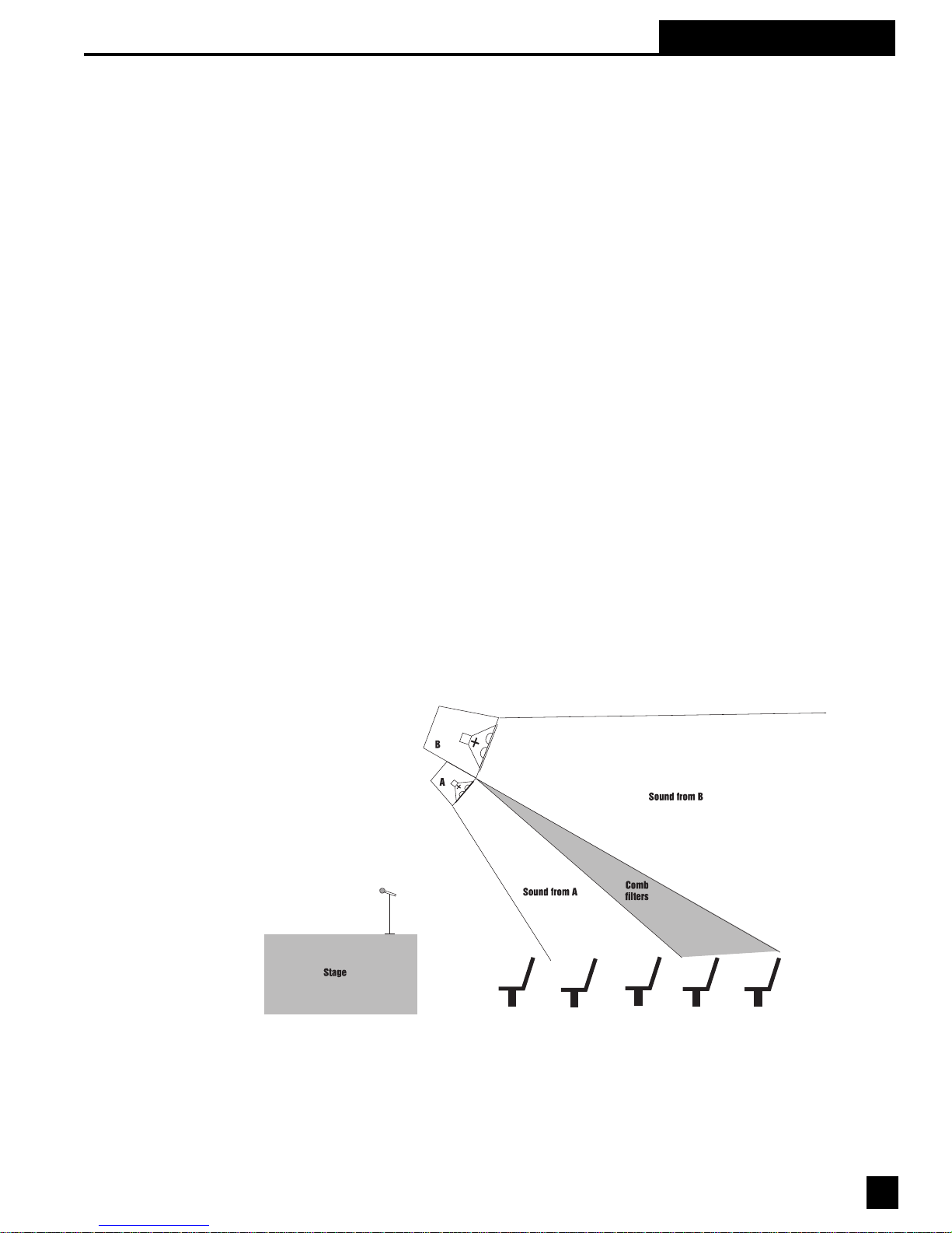
Application III: Synchronizing the signals of a far-throw and short-throw loudspeaker.
In order to reach the proper coverage in larger venues, we often stack two full range speakers - a
short-throw center cluster for the audience below and a far-throw speaker for the back of the
auditorium. It is almost impossible to perfectly align the stacked speakers mechanically, so comb
filter distortion becomes a problem in the area where the levels from both speakers are equal.
The same thing happens with speakers mounted on the right and left sides.
Fig. 14: Aligning far- and
short-throw speakers. (The
level from both speakers is
equal.)
It is impossible to remove comb filters with equalization, but the POWER-Q eliminates them in
short order without affecting the spectral balance for the rest of the audience. Find the axis where
the levels from the two speakers are equal. This is where the comb filters are most severe.
Carefully adjust the POWER-Q so that the signal from both speakers arrives at precisely the same
time. The POWER-Q provides 20 microsecond resolution for this purpose.
Use the same procedure to align speakers within a cluster when necessary .
19
Page 20
Section 8: Digital Delay
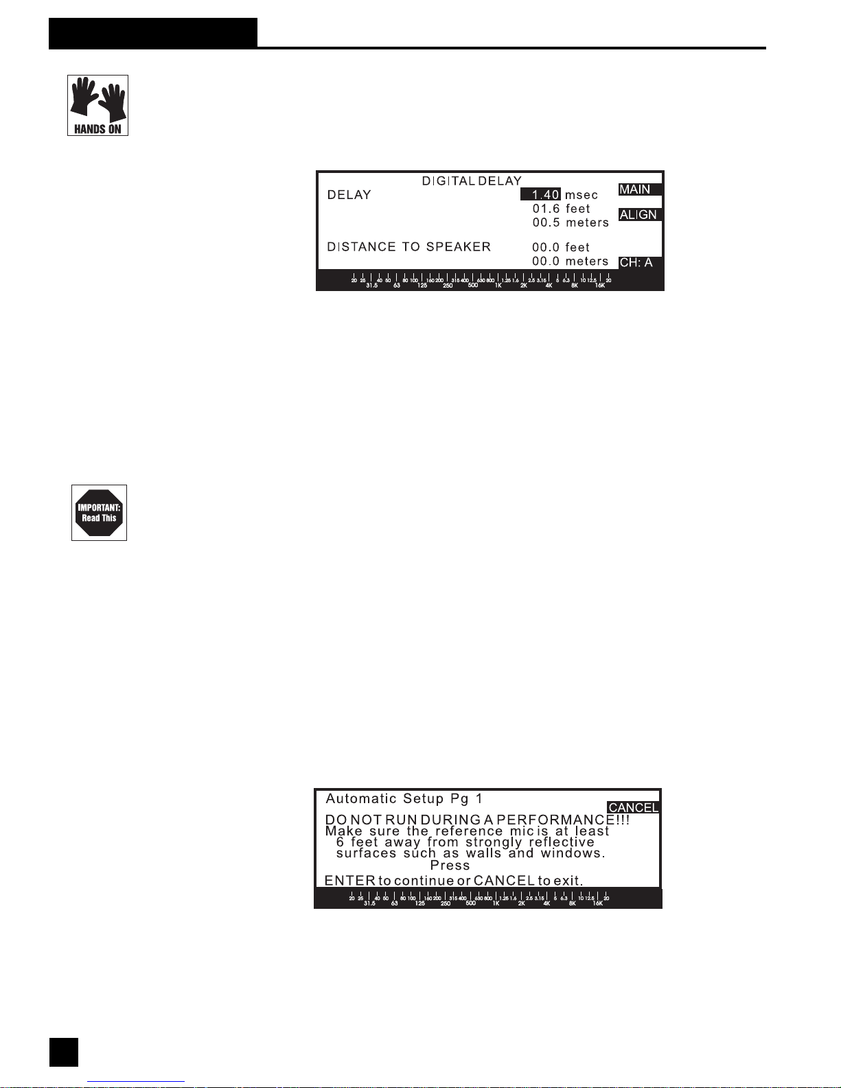
8.2 POWER-Q DIGITAL DELAY ADJUSTMENTS: Manual & Automatic. To access the POWER-Q digital
delay controls, choose #7 (“DIGIT AL DELAY” from the MAIN MENU. Use the up and down arrow
keys to scroll the MAIN MENU screen, and the soft key or ENTER key to select DIGITAL DELAY.
You will be presented with the following screen:
Fig. 15: Auto Delay page
You may set the delay time for channels A and B independently, either manually or automatically.
Manual adjustment. Delay time can be set in milliseconds, feet, or meters, with an adjustment
resolution of 20 microseconds (approximately 1 cm, or half an inch). Adjusting any one delay
parameter automatically changes the corresponding readout in the unselected measurement
units. The time unit display will always be the most accurate. (The distance displays are approximations based on the speed of sound at standard temperature and pressure conditions: 1 127 feet/
second at 20 degrees C and 760 mm Hg atmospheric pressure.) The minimum delay time
allowable is 1.38 milliseconds per channel; the maximum is 83.2 milliseconds.
Note that manually adjusting the digital delay during audio program may cause discontinuities
(popping sounds) while the adjustments are made. This is unavoidable and will cease when the
delay is set.
Delay times may also be set manually from inside the POWER-Q REAL-TIME ANAL YZER
window. Refer to Section 13.3 for more details.
Automatic Delay Alignment. If you have positioned a reference microphone for RTA analysis, or
Automatic Room EQ, the same microphone can be used by the POWER-Q to measure the
distance from the speaker to the microphone. (The qualities of the microphone are not an important consideration for delay alignment, although they are for EQ adjustments). The POWER-Q will
then set the delay times for its two channels to allow the sound from each speaker to reach the
microphone at the same time, compensating for the different distances from the mic to the two
speakers.
To execute Automatic Delay Alignment, press the ALIGN soft key in the DIGITAL DELA Y screen.
The following screen will appear:
Fig. 16: Auto Delay Setup page 1
20
Page 21
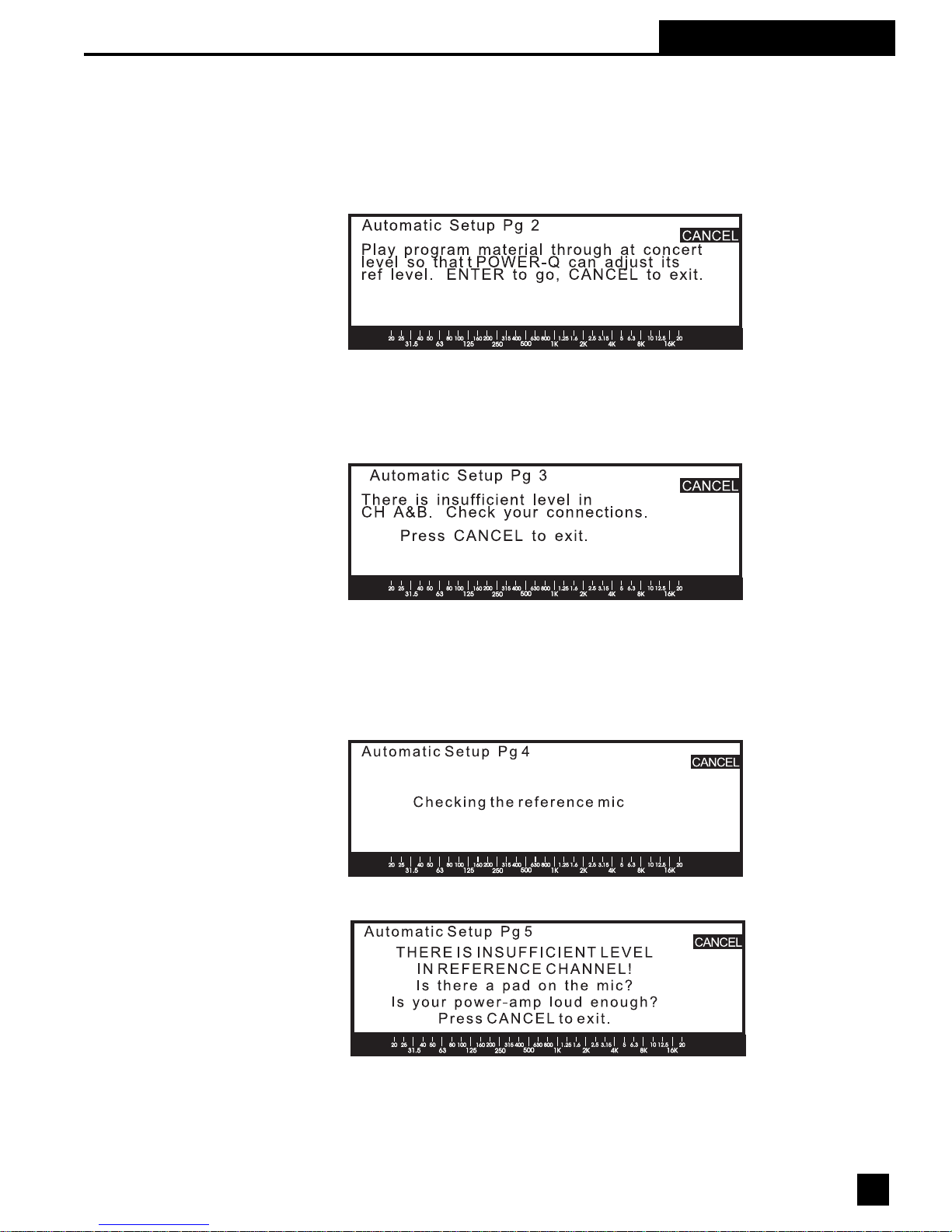
Section 8: Digital Delay
Your sound system must be set up and operational, and the gain of any equipment downstream in the signal path from
the POWER-Q must be turned up to operating level. You must also be able to play audio program (a prerecorded CD
will work fine) through the POWER-Q at concert levels. Finally , the reference microphone must be located in the
position you wish to use as your delay alignment reference.
When these conditions are met, press ENTER. The POWER-Q will display the following screen:
Fig. 17: Auto Delay Setup page 2
Play your audio program and press ENTER. The POWER-Q will verify that audio program is present at both inputs. If
there is no audio signal present in one or both channels, you will receive the following message. Note that there is no
reason to align speakers if you are only operating with one channel of the POWER-Q, and the unit will not allow you to
test only one channel when there is no signal present at one of its inputs.
Fig. 18: Auto Delay Setup page 3
Check your connections and signal path, and repeat the procedure.
If the POWER-Q detects the presence of a signal at its two inputs, it will automatically play a 1 Khz test signal, first to
calibrate the sensitivity of the reference microphone, and, second, to measure the time the signal takes to reach the
microphone after it is generated by the POWER-Q. This test will be repeated for the second channel. While the 1 Khz
signals are being tested, the POWER-Q will display page 4 as follows:
Fig. 19 : Auto Delay Setup page 4
In the event your microphone doesn’t hear a loud enough signal, you’ll see the following error message:
Fig.20: Auto Delay Setup page 5
21
Page 22

Section 8: Digital Delay
You may need to turn up your system gain downstream from the POWER-Q. Check your microphone and connections, and repeat the procedure as needed. Note that the POWER-Q will
automatically turn on or off the 20dB mic reference mic pad, as needed.
In rare instances, conditions may arise in which your microphone will not hear much energy from a
1KHz tone due to one of the following conditions:
· Crossover settings. If you are using a crossover that produces low frequency response at 1
KHz due to its settings, your system may not produce much sound in this frequency band, and
the reference mic may register insufficient level. Try changing your crossover frequencies.
· Room modes and phase cancellation. It’s unlikely but possible that the acoustics of the room
in which you’re set up may tend to de-emphasize 1KHz at particular locations, due to the outof-phase cancellation of direct and reflected sounds. Try moving your microphone position.
Once levels are sufficient, the screen below will appear:
Fig.21: Auto Delay Setup page 6
When the microphone hears the signal, the POWER-Q will time how long the signal takes to
reach the microphone from each channel’s output, and adjust the delay times to make the signals
arrive after the same length of time (subject to the 83.2 millisecond maximum value). The
POWER-Q will revert to displaying the DIGIT AL DELAY screen; however, each speaker’s output
delay , and the distance from each speaker to the reference microphone, will now be displayed,
and the speaker outputs will be aligned - as shown in the screen below:
Fig. 22: Auto Delay Report Screen
The entire procedure takes just a few seconds.
Note that the accuracy of the POWER-Q’s measurement of speaker distance will generally be
correct +/- approximately one foot. Higher frequencies than 1 KHz will produce greater accuracy ,
but may present other measurement problems for sound systems with roll offs in high end frequency response. In addition, in rare instances the reference microphone may confuse direct and
reflected sound, and err in its distance measurement by up to 5 feet. When in doubt, run the auto
setup several times and compare results.
22
Page 23

Section 9: Using The POWER-Q Automatic Room EQ
9.1 WHAT IS AUTOMATIC ROOM EQ? Sabine’s unique AUTOMATIC ROOM EQ feature is simply a
means of fast, automatic equalization, calculated by the POWER-Q on the basis of measurement
of acoustic energy heard at a reference microphone, and designed to provide a neutral, repeatable “starting point” for additional program equalization and signal processing. The EQ curve
calculated is designed to make the response curve heard at the microphone as flat as possible,
compensating for room acoustics and the frequency response of the sound system components.
9.2 HOW AUTOMATIC ROOM EQ WORKS. Sabine’s Automatic Room Equalization works in two steps:
1. Environmental Artifact Removal (EAR). First, the POWER-Q’s Environmental
Artifact Removal function measures the frequency response curve of ambient noise in the room,
as heard by the reference microphone placed in the optimal reference position. Most acoustical
environments exhibit some degree of unwanted sound artifacts (e.g., air conditioner rumble,
running fans). The POWER-Q measures this energy and calculates a temporary “noise curve.”
2. Room Analysis. Second, the POWER-Q measures the energy of pink noise played
through the sound system at the reference microphone. The POWER-Q will automatically boost
or cut frequencies to achieve as flat a room response as possible when the tones are played
through the sound system and heard at the reference microphone. This flat room response is
abbreviated “EQ RM” and is meant to serve as a consistent starting point for further adjustments.
Note that the frequencies heard and analyzed when the pink noise is played discount the “noise
curve” and represent only the interaction of audio played through the sound system and impacted
by the specific acoustics of the auditorium.
Section 9: Auto Room EQ
Note that the accuracy of measuring and compensating for ambient noise will improve when both
noise level and noise frequency are relatively constant. For best results, minimize or eliminate any
ambient noise sources when possible.
9.3. REFERENCE MICROPHONE CHOICE. Microphone placement, the type of microphone you
use, and the acoustics of the environment are important considerations for performing an
acoustic analysis such as the POWER-Q’s Automatic Room EQ. This is potentially quite a
complex subject and a complete discussion is beyond the scope of this manual. Any attempt to
equalize an acoustic environment will be subject to compromises and response variations from
one location to another. Nonetheless, it is possible to make adjustments that will improve the
system/room response for most if not all audience listening areas.
Ask 20 experts and you’re likely to get a variety of opinions and strategies about room equalization; suffice it to say that experience and your unique skill as an engineer will play a significant role
in your choice of mic type, model, and placement. For a more complete discussion on this
subject, please refer to John Murray's excellent article, "Doing the Right Thing" in the July/August
1997 issue of
For those of you who may want a relatively quick summary of what to consider about this topic,
read on.
Let’s first consider the type of microphone to be used.
LIVE SOUND! International.
First of all, the frequency response of the microphone should be as close to flat as possible, within
"1 dB from flat across the audible frequency range (20 Hz to 20khz), and should exhibit flat
response at both loud and quiet sound pressure levels. The greater the deviation from flat
response by the microphone, the greater the deviation from flat response your system may exhibit
when using the mic to set EQ.
23
Page 24

Section 9: Auto Room EQ
Most typically , either a cardioid, an omnidirectional, or a free-field microphone is used as a reference
microphone. A cardioid mic is directional in nature, that is, it is more sensitive to sound entering the front
of the capsule, in the same plane as the long dimension of the microphone, as shown below:
Cardiod mic
Fig. 23: Cardiod pick-up
pattern
rejects sound
from rear
An omnidirectional microphone is more equally sensitive to frequencies from all directions, also measured
in the plane of the microphone’s long dimension, as shown below:
Fig. 24: Omnidirectional pick-up pattern
A free-field microphone is a particular kind of omnidirectional microphone, designed to more closely
approximate the ideal free field (i.e., free from reflected sound) condition of a point-specific microphone
suspended in midair. Free-field mics are typically small diaphragm capsules (to minimize coloration from
sound reflections from the mic itself), and are generally pointed upward when used, to pick up sound in the
plane perpendicular to the plane of the length of the microphone, as shown below:
Sound Source
(facing mic)
Omnidirectional mics reveal no polar rejection of sound
Fig. 25: Free-field pick-up pattern
This orientation is more likely to produce accurate frequency response measurement in the same directional orientation as the ears of the listener, i.e., parallel to the floor and perpendicular to the apparent
direction of the microphone’s pointing.
In most circumstances a free-field microphone is the best choice for room analysis. However, in some
instances a cardioid mic may serve better. For example, in a small room, the direct sound field will be
much smaller in comparison to the reverberant field, and a cardioid ref mic aimed away from a close
reflective wall will minimize phase cancellation and coloration from reverberant sound.
The Sabine SQ-1000 is a free-field, exceptionally flat microphone, specially calibrated for use with the
Sabine POWER-Q and REAL-Q2. It is available from authorized Sabine dealers.
24
Free-Field Reference Mic in
Vertical Orientation
Page 25

Section 9: Auto Room EQ
9.4. REFERENCE MIC PLACEMENT It is an unfortunate reality of room acoustics that acoustic analysis may
vary quite a bit with differing reference microphone positions, depending on the size, shape and surface
reflections of the environment. For example, in very small rooms, or in the reverberant field of larger
spaces, the number of paths for sound reflection may produce less than optimal results due to the phase
interference patterns created by direct and reflected sound arriving at the reference microphone at different times. There are several rules of thumb you may follow to achieve the best, most accurate results of
room analysis:
· Position your reference mic where you think the audience will tend to congregate most, thus insuring
the best sound for the largest number of people.
· Keep the mic away from reflective surfaces (e.g., walls, corners, or large structures in the middle of a
room).
· Keep the mic relatively close to the front-of-house speakers (the direct sound field, where reflected
sounds are lower in magnitude relative to the sound coming directly from the speakers). The larger
the component of reflected sound in the sound heard by the reference mic, the greater the phase
cancellation and comb filtering.
· Bass frequency analysis is more prone to measurement anomalies than higher frequencies. The
smaller the room, the greater the problem. Use your ears and listen to bass response at different
room locations, in addition to considering the information and analysis of the POWER-Q.
· When running a mono sound source through two or more speaker stacks or enclosures, run Automatic Room EQ using only one speaker cabinet or stack, since sound arriving from multiple point
sources will arrive at the microphone at different times. When running a stereo source through a
stereo sound system, the POWER-Q will automatically analyze one channel at a time in sequence.
But again, multiple speakers in the sound path of either channel should be selectively disconnected so
only one speaker plays sound during the analysis.
NOTE: Make sure you plug only a microphone level signal into the POWER-Q reference microphone
input. Do not plug a microphone preamp into the reference input. This may cause the reference mic
board to overheat and damage the POWER-Q and will not be covered by the warranty .
9.5. POWER-Q CONTROLS FOR AUTOMATIC ROOM EQ. Select “AUTOMATIC ROOM EQ” from the display
window by pushing soft key #1 from the MAIN MENU.
Fig. 26: Automatic Room EQ, page 1.
Because pink noise is played at audible levels, do not run this procedure during a performance, or even
during rehearsal. Y ou should run the Automatic Room EQ procedure BEFORE the performers or audience arrive. To prevent accidental injection of pink noise through your sound system, the Automatic Room
EQ function requires you to deliberately choose the procedure by hitting the “ENTER” button when
prompted.
You may run the Automatic Room EQ analysis for either the A channel alone, the B channel alone, or both
channels in sequence depending on your application of the POWER-Q. Select “INIT A,” “INIT B,” or “INIT
A&B” using the left/right arrow keys before hitting the “ENTER” button to begin the analysis. NOTE: Any
time you run the Automatic Room EQ for a given channel, it will erase and replace the previous analysis
for the channel(s) chosen. In addition, the current program shaping curve will be erased from active
memory (though you may save the program curve and reload it from memory). For more information
about program shaping curves and memory options, see sections 10.2 and 16.0.
25
Page 26

Section 9: Auto Room EQ
Pressing ENTER displays Page 2 on the screen:
Fig. 27: Automatic Room EQ, page 2.
Make sure your POWER-Q is in place in the system (typically between the mixer output and the power
amp or crossover input), your system is turned on, your reference microphone is in the correct position,
oriented correctly , and plugged into the “Ref A” jack on the POWER-Q back panel, and you are ready to
play your audio program (a prerecorded CD will work fine) at performance levels.
High Frequency Roll-Off Compensation. The POWER-Q automatically calculates its room response curve to
either compensate or not for the high frequency roll-off detected by the reference mic as a function of
distance from the speaker playing the test signal. High frequencies are absorbed over distance to a
greater degree than low frequencies. If the reference mic detects attenuated high frequencies, the
POWER-Q will boost highs in the Room EQ curve to make up for this drop-off if “do not compensate” is
chosen. This may result in an overemphasis of high frequencies for audience members closer to the
speakers than the reference mic.
When the “Compensate” option is chosen, the POWER-Q inserts a high-frequency roll-off filter (12dB per
octave) to compensate for this overemphasis. The POWER-Q automatically measures the distance from the
speaker to the reference mic with a test tone, and calculates the appropriate roll-off, depending on the
speaker-to-mic distance. T o summarize, selecting COMPENSATE will cause the Automatic Room EQ
analysis to produce a response curve with more high frequency information at distances closer to the speakers.
In small rooms this compensation may not be necessary . To implement, simply highlight your choice to
compensate or not. Now play your test audio through the system. Set levels to concert volume, as the
POWER-Q will calibrate to the level you establish. Once the audio is playing, press “ENTER” again.
If the POWER-Q detects insufficient level at its inputs, this screen will notify you of the absence of signal in
either or both channels, as shown below:
Fig. 28: Auto Setup page 3
Note that this INSUFFICIENT LEVEL message refers to the INPUT audio signal present at either or both
inputs of the POWER-Q. You must play and audio signal (CD, tape or live music) long enough for the
POWER-Q to detect the signal and establish an operating level. This will typically take only a few seconds; then you can turn the audio signal. The input signal will be muted once the Automatic Room EQ
analysis begins.
If there is no signal in channel A or B, either your connections to the POWER-Q are bad, the POWER-Q may
be in bypass (“BP ASS” will flash in the upper right of your screen. Turn it off in the “GLOBAL P ARAMETERS”
menu.) or you are not providing an audio source to the POWER-Q. Check your connections, play your CD
and press "ENTER".
26
Page 27

Section 9: Auto Room EQ
When the POWER-Q detects an audio signal at its input(s), page 4 of the Automatic Room EQ menu will
indicate that the POWER-Q is testing the reference microphone for the presence of signal (a 1 KHz tone)
and calibrating the POWER-Q to the reference level heard by the microphone.
Fig. 29: Automatic Room EQ, page 4.
If a weak signal (or no signal) is detected at the reference microphone input, the POWER-Q will prompt
you with Page 5:
Fig. 30: Automatic Room EQ, page 5.
Note that this INSUFFICIENT LEVEL message refers to the audio detected by the reference microphone,
NOT the signal present at the channel inputs of the POWER-Q Make sure you are using a working
microphone plugged into the “REF A” input on the back of the POWER-Q with a correctly wired cable. If
you are using a reference mic that requires phantom power, turn on the phantom power in the “GLOBAL
P ARAMETERS” section, accessed from the MAIN MENU. If all else fails, try moving the microphone. It's
possible your position may not permit the microphone to "hear" the 1kHz tone due to phase cancellation.
In rare instances (e.g., extremely loud conditions) it’s possible that the signal heard at the reference mic
input might be too "hot", which will produce an alternative error message:
Fig. 31: Automatic Room EQ
Alternative page 5.
You may need to put a pad on the microphone or at the POWER-Q input (via Global Parameters). Alternatively , try placing the microphone a further distance from the speakers.
Once your reference microphone is plugged in, positioned correctly and working, the Automatic Room EQ
analysis will begin, as indicated by page 6 of the menu.
Fig. 32: Automatic Room EQ, page 6.
The POWER-Q plays a burst of pink noise for a few seconds, measures energy per octave as heard at the
reference mic input, and performs thousands of calculations to adjust its graphic EQ filters to make this
response as flat as possible. The entire process will take about 10 seconds per channel. Then page 6
screen will indicate the POWER-Q channel being analyzed.
27
Page 28

Section 9: Auto Room EQ
When the analysis is complete, the POWER-Q will display page 7:
Fig. 33: Automatic Room EQ, page 7.
The analysis shows the high and low frequency roll-offs inherent in your sound system, and this
screen allows the user the option of having the POWER-Q insert matching high pass and low
pass filters. Press ENTER to insert the HPF and LPF, or press CANCEL if you choose not to
insert roll-offs. Either ENTER or CANCEL will return you to the MAIN MENU. Note that if your
system response is quite flat from 20 Hz to 20 kHz, page 7 will not be displayed, and the
POWER-Q will return you to the MAIN MENU.
It is possible to interrupt the Automatic Room EQ function at any time by pressing the “CANCEL” soft key. This will return you to the MAIN MENU. If you do this after the procedure
begins, but prior to its conclusion, the ROOM EQ response will be reset to zero boost/cut.
Important: Note that the AUTOMATIC ROOM EQ function will NOT add more than 6 dB boost
to any EQ slider.
Also, note that the Graphic EQ screen on the POWER-Q will NOT show any boost or cut of
sliders after the Automatic Room EQ function is completed. The Auto Room EQ settings are
shown only as a superimposed response curve, leaving the EQ sliders free for you to make
additional changes to the EQ (what we call Program EQ). The total EQ and filtering added by
the POWER-Q will produce an EQ curve that can be displayed by pressing the third soft key
(CURVE/CU A/CU B/CUA&B), which selects the curve display you desire (either channel singly ,
both channels together, or no curve). Prior to adding (or when bypassing these features, using
the BYP ASS screen from the MAIN MENU) any additional filtering or program EQ, this curve
will display the adjustments calculated by the POWER-Q to make the room/system response
as flat as possible at the reference microphone position. Different curve display options thus
can show the results of separate POWER-Q EQ adjustments or all adjustments together. For
more information, see Section 10.
28
Page 29

Section 10: Using The POWER-Q Graphic Equalizer
10.1 GRAPHIC EQUALIZER APPLICATIONS. Automatic Room EQ or an RTA analysis will produce a
room EQ curve that may best be regarded as a starting point or baseline for further fine tuning with
the second level of POWER-Q graphic EQ controls, which are user adjustable. Experienced
graphic equalizer users employ a variety of methods to arrive at their preferred sound, and the
POWER-Q allows your personal touch in determining the way your system sounds.
A graphic equalizer is an engineer’s most common choice for compensating for less than ideal
acoustical reproduction. The quality of equipment used, the placement of speakers and the
acoustical properties of a room will rarely result in tonally balanced sound reproduction. Even the
best sound equipment will not produce sound to its optimal potential in most acoustical environments; for example, reflective parallel room surfaces (wall to wall, floor to ceiling) will create
standing waves and acoustic resonances that will vary as a function of room dimensions.
A multiband graphic equalizer can compensate for unequal acoustical energy across the frequency
bands of the audio spectrum. The POWER-Q graphic EQ provides you with a choice of measurement and calibration aids to perform automatic equalization, or it will allow you to rely on your own
experience and hearing acuity to equalize an acoustical space. Y ou can even combine methods. In
fact, the POWER-Q goes a step further, providing you with some very powerful advantages for making a sound system sound as good as it can. Y ou can arrive at a baseline “flat response” curve by one
of two methods: by performing the POWER-Q Automatic Room EQ function (see Section 9), or by
using the RTA to analyze pink or white noise played through your sound system into a reference
microphone (see Section 13). However, you may not want to stop there. Many sound engineers can
improve the sound of a flat response system and will tweak the sound of the EQ further, perhaps
changing the overall frequency balance to match the performers’ style or the requirements of a particular application. In such situations, the POWER-Q truly lives up to its name.
Section 10: Graphic EQ
To fully understand the powerful options made available with the POWER-Q, think of the unit as
containing two separate graphic EQs. The “first” EQ is automatically set by the POWER-Q using
the Automatic Room EQ function (see Section 9). Its function is to make the frequency response
of the acoustical environment as even as possible, or flat. We call this response curve the “Room
EQ.” Although the POWER-Q makes graphic EQ adjustments to produce the Room EQ, the
actual slider settings for these adjustments are NOT displayed; instead, the graphic EQ screen will
display a graphic EQ settings as flat. Think of this as the default starting point for you to sculpt
sound, adding EQ as needed for the various applications you may use for the POWER-Q, even in
the same auditorium.
In actual practice, many or most sound engineers will choose to adjust EQ settings differently for
various applications. For example, the system EQ desirable for a hip-hop artist would likely require
more low end boost than would be appropriate for an acoustic folk artist. This additional application-specific EQ is the “second” EQ added to the sound. Let’s call it the “Program EQ.”
The actual total EQ added to your program by the POWER-Q is the combination of Room EQ,
Program EQ, FBX filters, parametric filters, and high and low pass filters. The resultant total curve
reflecting all these changes can be viewed in both the graphic EQ and FBX/Parametric Filter
screens. This curve shows a combination of all EQ and filtering currently active in the POWER-Q;
bypassing Room or Program EQ (see Section 22) will change the curve display accordingly . A
Hardware bypass will simply bypass all the processing of the POWER-Q, and the curve display will
NOT change, though the EQ shown will not be in the signal path.
Only the Program EQ will be saved and recalled by the POWER-Q. The Room EQ will be stored
in memory (even after the unit is turned off) as the default Room EQ, and will remain in the signal
path unless it is bypassed (Section 22), reset (Section 10.2), or until another Automatic Room EQ
procedure is run. Then the results of the new analysis will become the Room EQ default. The
reasoning for this is quite simple: every room is different (even the same room will have differences from one performance to the next), and calibrating your system (with Automatic Room EQ,
which takes only seconds) insures optimal performance in the new space. We even encourage
you to re-Auto EQ the same room periodically . Once your Room EQ is set, you’ve established the
29
Page 30

Section 10: Graphic EQ
same “flat” starting point for further EQ changes, and now you can add (by programming, or from one
of the 99 POWER-Q memories) your favorite Program EQ.
The POWER-Q allows you to develop and save Program EQs and load them into the POWER-Q graphic
EQ with the touch of a button. An engineer who works with a variety of acts that each require a specific
program curve will be able to customize an EQ curve for each act and name, save, and recall each curve
quickly. In a new acoustical space, by performing the Automatic Room EQ procedure followed by the
recall of a Program EQ, a sound engineer will achieve these powerful advantages:
• Consistency of sound.
• Quick setup. You should be able to EQ the system in just a few minutes.
• Quick and reliable change of EQ from one performer to another.
• Predictable change of EQ in mid-performance.
• Quick loading of EQ templates to match the style of new or unfamiliar performers. Amaze them
with how quickly you catch on to their sound!
Please note that the total boost (including Room and Program EQ) for any EQ slider is limited to a total of
12 dB; the limit for any slider’s cut (Room and Program combined) is 15 dB. Automatic Room EQ alone
will not impose a boost greater than 6 dB, or a cut greater than 15 dB.
10.2 POWER-Q GRAPHIC EQ SCREENS AND OPTIONS: GRAPHIC EQ, CURVE DISPLAY, RESET FILTERS To access
the POWER-Q Graphic Equalizer controls, press soft key #2 (“GRAPHIC EQ”) from the MAIN MENU.
(The MAIN MENU options can be scrolled using the “MORE” button or up/down arrow keys.) Pushing
this key will display the image of a 31-band graphic equalizer on the screen. The frequency midpoints
of each band are displayed at the bottom of the equalizer window.
There are two pages to the GRAPHIC EQ controls, accessed by pressing the “MORE” button. Pressing “MORE” changes the bottom soft key function from Channel Selection to Curve Selection.
Channel Selection and Slider Adjustment. Press “MORE” until soft key #4 reads “A,” “B,” or “LINK.”
This key selects the POWER-Q audio channel controlled by the EQ sliders.
Selected Slider
Number
Fig. 34: Graphic EQ Screen
The “LINK” feature maintains the relative levels of the two channels while moving both. Use the left
and right arrow buttons to choose the filter you wish to adjust (as indicted by the cursor at the bottom
of the screen). The data wheel will move the sliders up or down. The “A” channel position indicator is
a hollow square; the “B” channel is indicated by a smaller, solid rectangle. When the two channels’
position indicators are at the same point, they will show as a large solid square.
Selected Slider
Frequency
Slider Select
Channel A
Slider Depth
Channel B
Slider Depth
Channel A
Position Indicator
Channel B
Position Indicator
Go To Main Menu
Allows you to reset all filters
for both channels, either
globally or individually.
CU A/CU B/CU A&B:
Allows you to see the total EQ
curve for channel A, B or A&B.
A/B/LINK:
Allows you to toggle between
channels or link them together.
30
Page 31

Curve Display . One powerful feature of the POWER-Q is its ability to display the total frequency
response curve at the output stage of the unit, integrating all its equalization (graphic, parametric,
FBX, and high and low pass filters).
Fig. 35: Curve display
This curve is superimposed on the graphic screen and is accessed by pushing the soft key labeled
“CURVE.” This key can be toggled to show the frequency response curve of channel A (“CU A”),
channel B (“CU B”), or both channels together (“CU A&B”). These curves represent the combination
of ALL (graphic, parametric, FBX, and HPF/LPF) EQ settings in the POWER-Q. The superimposition of the response curve on the slider screen allows you to see the overall EQ resulting from
graphic EQ adjustments with the front panel controls. The response curve is offset above the “flat”
(zero boost or cut) center position of the EQ sliders in order to facilitate the display . This does not
indicate any overall level boost from the POWER-Q.
Note that the Curve Display can be viewed in either the Graphic EQ screen, or in the FBX/Parametric EQ screen (see Section 1 1.3).
Section 10: Graphic EQ
Curve Display and Bypass. The curve displayed combines all the EQ and filtering active in the
POWER-Q signal path. If either the Program EQ or Room EQ is bypassed (or if both are bypassed,
as described in Section 22), the curve display will reflect the bypass.
Reset. The “RESET” button (soft key #2) opens up a screen that will allow global resetting of all
filters for both channels or separate resetting of FBX, parametric or program EQ or room EQ filters
for the A and B channels. It is possible to reset all FBX filters or just dynamic FBX filters.
Fig. 36: Reset filters screen
To execute an option, arrow to your choice and push the “ENTER” button. If you select any option
other than “ALL OF THE ABOVE...”, your reset command will be executed, but the screen menu will
remain until “CANCEL” is pushed, in order to allow you to reset more than one type of filter with a
minimum of commands and screen changes. Press CANCEL when you have reset all the filters you
want. Selecting and executing “ALL OF THE ABOVE...” will return you to the graphic EQ screen
without the CANCEL command being necessary . Please note that “ALL OF THE ABOVE...” will not
reset Room EQ, which must be reset individually .
31
Page 32

Section 11: FBX/PARAMETRIC EQs
Section 11: Using The POWER-Q FBX/Parametic EQ
11.1 TYPES OF FILTERS: Fixed FBX, Dynamic FBX and Parametric, FBX Feedback Exterminator Filters.
The POWER-Q is the most recent refinement of the patented Sabine FBX technology that allows
the unit to automatically sense and eliminate feedback. The POWER-Q offers two types of FBX
automatic feedback control filters: FIXED and DYNAMIC. FIXED filters provide gain before feedback. DYNAMIC filters eliminate transient feedback that comes and goes throughout the program.
Follow the procedures described on pages 9 & 33 to “teach” the FBX automatic feedback control
filters the frequencies and depths necessary to control feedback in your system.
BACKGROUND: The POWER-Q uses a sophisticated algorithm (patented) to monitor the input
signal and detect the onset of feedback. The FBX algorithm is fast, accurate and unique in its
ability to distinguish feedback even when audio signal is present. When feedback occurs, the
algorithm makes a precise determination of the feedback frequency and sets a filter of prescribed
width (typically 0.10 octave, but this can be modified in the GLOBAL P ARAMETERS menu) at that
frequency . Initially, the filter is only -3 dB deep, which is often sufficient to eliminate the feedback.
If the same feedback frequency persists, the filter is deepened progressively to a maximum depth
(which is also user-selectable) or until the feedback is eliminated.
FIXED FBX filters are used to eliminate feedback due to characteristics which are unlikely to
change, such as room acoustics and fixed microphone installations. Once a FIXED filter is set, its
center frequency remains fixed, but it may be deepened automatically , if necessary, to control
additional feedback at the same frequency . The POWER-Q gives you the option of locking the
fixed filters so they won’t go deeper than the original setting. This feature is especially useful in
unattended P A systems. The third soft key button (“LOCK+/-”) locks and unlocks the fixed FBX
filters. The "FBX F" (fixed) filters change to "FBX L" when locked.
DYNAMIC FBX filters are used to deal with transient feedback that comes and goes during a
program. Changes in room acoustics (due to temperature or audience size changes), changes in
gain (musicians almost always play louder during a performance than at sound check) and changes
in mic position (e.g., with a wireless mic) often result in new feedback frequencies arising during
performance. When a new feedback frequency occurs, a new DYNAMIC FBX filter is automatically
assigned to eliminate the feedback. When all of the DYNAMIC filters have been used, the filter that
was set earliest is reassigned to handle subsequent feedback, and so on.
One trait shared by both the FIXED and DYNAMIC FBX filters is their ability to track feedback. We
have already said that DYNAMIC FBX filters will set new filters or recycle old filters to eliminate
feedback and that FIXED FBX filters are not recycled. If, however, the feedback frequency is
detected to be very close to an existing feedback frequency , it is presumed that this new feedback
is the result of a “drift” in the resonating frequency of the original feedback. Drifting can be the
result of changes in air temperature or humidity . In this case, the closest filter will automatically
move slightly to the new frequency to track this feedback. Y ou can adjust the tracking values in the
GLOBAL P ARAMETERS menu.
If the P.A. system is moved from the original setup, the POWER-Q must be “retaught” where to
place filters to eliminate feedback. To reset, press the “MORE” button until the option “RESET”
appears next to the second soft key button. Press “RESET,” and you will be given the option of
resetting all filters or just the FBX, graphic, or parametric filters for one or both channels. (See the
section on GLOBAL P ARAMETERS for more information about controlling FBX automatic feedback
control filters.)
P ARAMETRIC FILTERS. If a filter type is set to “PARAM” (parametric), it is possible to edit its
frequency , width and depth by moving to the appropriate field with the arrow keys while in the LIST
mode (press the second soft key button, “LIST/CURVE,” until you see a table of filters). You can
set the center frequency of POWER-Q parametric filters anywhere between 20 Hz and 20 KHz with
1 Hz placement resolution. The filter’s WIDTH ranges from 9.99 octaves to 0.01 octave. The
DEPTH can be set anywhere from -84 dB cut to +12 dB gain in 1 dB increments. These parameters are set using the arrow keys to choose the correct parameter and the data wheel to change
the parameter value.
32
Page 33

Section 11: FBX/PARAMETRIC EQs
You can also edit the parametric filters in the CURVE mode, accessed by pressing the second soft
key button (“CURVE/LIST”) until you see a frequency-by-amplitude display . This gives you an EQcurve view of the filters edited in the LIST mode, plus allows “click and drag” graphic editing for
parametric filters using the arrow keys to choose a filter’s frequency , width, and depth, and the
data wheel to vary the parameter. The change will be displayed visually and audibly as the
parameters are varied.
Note that the curve displayed is a combination of all filters (parametric, FBX, HPF, LPF and
graphic) in the signal path for the selected channel. This is not only a powerful visual aid, showing
the combined effects of all the EQ and filter changes you’ve made, but also a handy “final tweak”
stage for your overall EQ. Assuming you have at least one unused parametric EQ filter, you can
add this to your overall EQ curve with “click and drag” editing, which is easily done on the fly in the
heat of live mixing.
If the filter frequency is set to "off," the width and depth cannot be entered. The POWER-Q
assumes the filter does not exist.
Unlike many conventional analog parametric filters, the POWER-Q’s digital filters do not drift with
temperature or cause phase-shifting outside of the filters.
A fixed or dynamic FBX filter that has been set by the POWER-Q can be “frozen” by moving to the
appropriate type field and changing it to “P ARAM.” At this point, the filter can be left as is or edited
further. You may also decide to "consolidate" two or more closely spaced FBX filters into a single,
slightly wider parrametric filter. Then reset your FBX filters and eliminate even more feedback
with a second set up. (See Section 23, A Pro’s Guide to Using the ADF Products, by Ken
Newman.)
11.2 FBX/TURBO/AUTO TURBO SETUP MODES. You are provided with three optional methods (use
these ONL Y for setup) of identifying and eliminating feedback frequencies. For any of the modes,
you must have your sound system set up, plugged in, and all your microphones in place and
turned on. The three methods of setup are:
· Normal (default) mode, which involves simply configuring your FBX filters as you desire (see
Section 1 1.1), then slowly raising the master mixer output (assuming the POWER-Q is inserted
between the mixer and the power amp) with all the mics that might create a feedback problem
open and turned on. As feedback occurs, the POWER-Q will automatically set filters until you’ve
achieved the additional gain you desire, or until you’ve engaged all the filters available.
· Turbo Setup mode maximizes the POWER-Q clip level and sets all FBX parameters to a
more sensitive-to-feedback condition then normal operation. It also places a “moving limiter”
that tracks gain changes as feedback occurs, but allows the feedback to occur at a quieter
level. Feedback is created by slowly raising the master mixer output with all the mics that
might create a feedback problem open and turned on.
· Automatic T urbo Setup mode is a form of Turbo Mode that lets the POWER-Q automatically
control the gain and automatically “ring out” feedback frequencies. Automatic Setup also
imposes a limiter on the feedback volume, thus allowing system setup with quiet feedback
levels. This is the greatest benefit for ears since Mike Tyson was banned from boxing!
Normal FBX setup mode notes. Here’s is a step-by-step guide to setting up the FBX function:
1. Place the microphones and speakers in the locations where they will be during the program,
and patch in the POWER-Q using one of the setups described on page 8. Set all controls for
your sound system at the settings that will be used during the performance, with this exception:
Y ou should set up one channel at a time by turning the other channel all the way down on your
mixer or power amp.
2. First, make sure the main sliders on the mixer are pulled down, then power up the sound
system, the POWER-Q and finally the power amp.
33
Page 34

Section 11: FBX/PARAMETRIC EQs
3. Select soft key #3 ("FBX and PARAMETRIC FILTERS") from the MAIN MENU, and make any
adjustments to the default configurations.
4. Slowly raise the gain (for one channel only). As feedback begins to occur, the FBX filters will
automatically detect the correct feedback frequency and apply a narrow filter to eliminate it.
Continue raising the gain until all FBX fixed filters are set. If you wish to lock the FBX fixed
filters to prevent them from notching more deeply , press the "LOCK+/-" soft key at the right of
the screen so it reads "LOCK+."
5. Repeat this procedure for the other channel.
T urbo Setup notes : Here is a step-by-step guide to using the Turbo function:
1-3.Follow steps 1-3 as above.
4. Press the “Turb+/-” soft key, to open up the Turbo screen, as shown:
Fig. 37: Turbo Warning Screen
5. Highlight “Turbo” using the arrow keys.
6. Slowly raise the gain (for one channel only). As feedback begins to occur, the FBX
filters will automatically detect the correct feedback frequency and apply a narrow filter to
eliminate it. Continue raising the gain until all FBX fixed filters are set. If you wish to lock
the FBX fixed filters to prevent them from notching more deeply , press the "LOCK+/-" soft
key at the right of the screen so it reads "LOCK+."
7. Repeat this procedure for the other channel.
Auto Turbo Setup notes: W ith Auto Turbo Setup follow these steps:
1-3.Follow steps 1-3 of normal FBX setup.
4. Press the “Turb+/-” soft key, to open up the Turbo screen.
5. Highlight “Auto Turbo setup” using the arrow keys.
6. Bringing your system’s gain to the point where feedback just begins (by turning up
your master mixer output), then execute the Auto Turbo setup command by pressing
the ENTER button.
7. At this point, the POWER-Q automatically takes over gain control. As the POWER-Q
slowly increases its output gain (in half dB increments) to create feedback, a window will
appear at the bottom of the screen to show the increase in gain before feedback.
8. Auto Turbo Setup stops when the POWER-Q has automatically raised gain and set filters
until either all the filters, or the first dynamic filter, have been engaged.
9. When Auto Turbo Setup concludes, the final level of the POWER-Q is returned to its
starting point, and the total amount of feedback-free gain you’ve added to your system is
displayed.
10. Repeat this procedure for the other channel.
34
Page 35

Section 11: FBX/PARAMETRIC EQs
When Turbo or Auto Turbo is engaged for either channel A or B, the corresponding Clip LED on
the front panel of the POWER-Q will blink, and the soft key will change to indicate "Turb+".
Auto Turbo setup will add gain to the POWER-Q’s output, to a maximum of 20 dB, or until the first
dynamic filter is set. If the 20 dB maximum is achieved, it’s likely that your sound system gain
structure should be reconfigured. You may need to add more gain at your mixer inputs or outputs,
or at your power amplifier.
We recommend using the Auto Turbo Setup to take advantage of all the POWER-Q’s processing
and ease of use. But regardless of the method chosen to eliminate feedback, the results will be
identical: increased gain without sacrificing clarity . In addition, once setup is complete, fixed filters
are set, and the performance begins, any new feedback problems (such as those caused by a
roving wireless mic) will be filtered by Sabine’s proprietary dynamic FBX filters.
TURBO mode should be turned off when the POWER-Q is in normal operating mode.
This
will usually happen automatically during setup. There are five ways to turn off Turbo mode::
1. By toggling the soft key to read "TURB-";
2. By hitting the "LOCK+/-" soft key (accessed by pressing the MORE button);
3. By setting at least one dynamic FBX filter (automatically takes the POWER-Q out of
TURBO mode; TURBO soft key selection disappears);
4. By loading any program curve from the POWER-Q memory; or
5. By turning the POWER-Q off and back on.
If the Turbo mode is somehow left on when the FBX setup procedure is completed (or ended
prematurely), you may experience distorted audio through the POWER-Q since the clip level will
be turned up fully , and easily overloaded by input level. This problem is easily remedied by turning
Turbo mode off. Turbo mode will NOT affect the output level of the POWER-Q.
NOTE: The “Turb+/-” soft key will be ghosted after setup is completed, and will remain unavailable until FBX filters are reset for the appropriate channel(s).
11.3 POWER-Q FBX/PARAMETRIC FILTER ADJUSTMENTS. There are two pages of soft key options
under "FBX and Parametric Filters" (MAIN MENU option #3). Press the “MORE” button to access
all the available options of this menu.
Selected Filter
Number
Selected Filter
Type
Selected Filter
Frequency
Selected Filter
Width (ranges from
.01 to 9.99 octaves)
Selected Filter
Depth (ranges from
+12 to -84 dB)
Fig. 38: Filter options screen
"Click and drag" crosshair cursor
to edit parametric filters.
The “MAIN” soft key returns you to the MAIN MENU.
The “CURVE/LIST” button toggles between the LIST mode, a tabular listing of filters and control
parameters, and a graphical representation of a frequency response curve (CURVE mode),
showing the total curve for either channel of the POWER-Q as it is affected by all of the EQ
adjustments you have made (including graphic, parametric, FBX, and high and low pass filters).
Both the Curve and List displays are available for either the A or B channel, selectable with the
fourth soft key button.
24
GOTO Main Menu
Toggles between CURVE view
and LIST view.
TURB+/TURB+ turns on TURBO setup
mode; TURB- turns it off.
Toggles between channels A
and B.
35
Page 36

Section 11: FBX/PARAMETRIC EQs
11.4 FILTER CONTROL MENU: LIST MODE AND CURVE MODE
Fig. 39: Filter menu control
LIST MODE: The POWER-Q provides up to 12 filters per channel for parametric equalization or
feedback control. Each of these 12 filters can be set to any of the three types of filters: parametric, FBX fixed or FBX dynamic. Only six of the filters are displayed at a time; the remaining six will
be displayed when the arrow keys are used to scroll “above” or “below” the screen currently
displayed. Arrowing down from the 12th filter accesses the controls for setting high pass (HPF)
and low pass (LPF) filters for each channel individually .
Use the arrow keys to move the cursor to the "Type" field of the filter you wish to change. Rotating
the data wheel will select among three filter options: parametric, FBX D (for dynamic) and FBX F
(for fixed). The third soft key button (“LOCK +/-”) locks the FBX F filters (they are locked when the
display reads “LOCK+”) and will cause relevant filter labels to read “FBX L.” This button should be
toggled to “LOCK-” until the FBX fixed filters are set.
Fig. 40: Curve Mode
CURVE MODE: Pressing the “CURVE/LIST” soft key switches the tabular LIST mode to a frequency
response plot representing the sum total of all EQ settings (graphic, parametric, FBX, HPF, LPF)
in channel A or B. Soft key #4 selects which channel’s curve is displayed.
The top line of the "Curve" mode display shows the filter number (1 through 12, high pass, low
pass), the type of filter that corresponds to that number, the frequency of the filter, and its width
and depth. These values will correspond to the settings in LIST mode. The filter chosen for this
top line can be changed using the up/down arrow keys. (NOTE: This is important, as all other
parameters are adjusted using the data wheel after selecting parameters with the left/right arrow
keys.) When the displayed filter is set to “P ARAM” using the data wheel, the frequency, width and
depth of the parametric filter can be changed by using the arrow keys and data wheel.
For example, let’s say we want to add a parametric notch at 60 Hz, 10dB deep, and 0.20 octaves
wide. While “P ARAM” or “FBX L/F/D” is highlighted, use the up/down keys to select the number
of the filter (1 through 12) you wish to use. Using the data wheel, select “P ARAM” as the type of
filter. Press the right arrow key to highlight "Frequency," and turn the data wheel to set “60.” (You
will see the position indicator on the screen move as you change this value. If you’re adding to an
existing EQ curve, the position indicator will follow the line of the curve.) Use the right arrow key
to move to “Width,” and set this to “.20.” Move to the right one more time to “Depth,” and use the
data wheel to set this value to “-10.”
Both the graphic display and the audio program will change in real time to reflect these changes.
The cursor traces the existing displayed curve until you change the “Depth” value up or down from
zero, and the actual curve display and audio will only change when a boost or cut is set. It is also
possible to preset a boost or cut with frequency set to “off,” and then sweep the boost/cut through
all the audio frequencies until you find the sound you like. (This makes for quite an interesting
36
Page 37

flanging sound if you use a wide filter while listening to audio through the POWER-Q!)
This is a very powerful feature that allows visualization of “on-the-fly” fine adjustments of EQ. Y o u
can refine your system EQ curve with a touch of parametric EQ added to the response curve
you’re already working with - and you can see and hear the results instantly .
11.5 THE MORE BUTTON FOR THE FBX/PARAMETRIC WINDOW. Pressing the “MORE” button in the
FBX/Parametric window accesses the “RESET” and "LOCK+/-" soft keys.
Fig. 41: Pressing "MORE"
gives you these options
The "RESET" key gives you the choice of resetting all filters or selected banks. These choices
are identical to the options for resetting filters in the Graphic EQ window (see section 10.2).
Section 11: FBX/PARAMETRIC EQs
Go To Main Menu
Allows you to reset all filters
for both channels, either
globally or selectively.
LOCK+/Locks (LOCK+) and unlocks
(LOCK -) fixed FBX filters.
Toggles between channels A
and B.
The "LOCK+/-" soft key locks (+) and unlocks (-) fixed FBX filters. A locked FBX filter will not
change or notch any deeper.
11.6 PREVENTING FEEDBACK IN THE EVENT OF EQUIPMENT FAILURE. If you’re concerned about the
potential feedback problems that may arise in the very unlikely event of a POWER-Q failure during
a performance, you can relieve your concerns by programming a 10dB boost into the output signal
path (see Section 17). If power to the unit is interrupted, system gain will be reduced by 10dB,
enough to prevent feedback from occurring.
37
Page 38

Section 12: High/Low Pass
Section 12: Using The POWER-Q High & Low Pass Filters
The HIGH and LOW P ASS FILTER controls are accessed via the “Parametric and FBX Filters”
menu selection (option #3). Pressing the down arrow key repeatedly (while in the LIST mode, or
under “TYPE” in CURVE mode) through all 12 filters ultimately shows the HIGH and LOW PASS
FIL TER menu.
Fig. 42: High and low
pass filters (list
mode)
Fig. 43: High and low
pass filters (curve
mode)
These are the high- and low-end roll-off filters that are used to custom-tailor the low- and high-end
frequency response. A “high pass filter” allows frequencies higher than a set value to pass; in
other words, it filters out low frequencies, and the opposite happens with a “low pass filter.” The
HIGH P ASS FILTER can be used to suppress phenomena such as low-frequency rumble, while
the LOW P ASS FILTER can be used for attenuating high-frequency hiss or for band limiting the
POWER-Q’s output signal for telecommunications.
This screen allows setting of the high and low pass filter points. The HIGH P ASS FILTER can be
inserted starting at any frequency up to 3,000 Hz. The LOW PASS FILTER can be inserted from
1,000 to 20,000 Hz.
Note that turning the data wheel to the extreme low range of the HPF and the extreme high range
of the LPF turns the filters off.
38
Page 39

Section 13: Using The POWER-Q RTA
13.1 USING A REAL-TIME ANALYZER. Although it is possible to achieve excellent results setting up
the EQ for a room using the POWER-Q’s Automatic Room EQ (see Section 9), many engineers
prefer to perform a REAL-TIME ANAL YSIS of a sound system and make equalization adjustments
based on the results. Y ou may elect to do this in lieu of, or in conjunction with, Automatic Room
EQ.
RTA analysis involves generating noise (usually pink noise) through a sound system and observing the energy across frequency bands as heard by a reference mic positioned in the acoustical
environment. Adjustments are made to an equalizer until the response curve of the system, as
heard by the reference mic, matches the specifications of the operator.
The RTA feature of the POWER-Q offers a no-compromise, filter-based RTA that will equal or
surpass the performance of other brands and models on the market that cost as much or more,
yet offer none of the POWER-Q’s other features.
13.2 POWER-Q RTA ADJUSTMENTS. An R TA analysis will require the POWER-Q’s built-in noise
generator (pink or white) and a reasonably flat response microphone (we recommend the Sabine
SQ-1000 ) plugged into the “REF A” jack on the back of the POWER-Q. You may select the
“REAL-TIME ANAL YZER” option by pressing the #4 soft key in the main menu. The screen will
look like this:
Graphic EQ Sliders
When either 30 or 15 dB scale is
chosen, arrows appear ; they
indicate you can scroll up or down
the scale in 5 dB increments using
the front panel up/down arrow
keys .
Fig. 44: RTA screen
The “MAIN” soft key returns you to the MAIN MENU.
Section 13: RTA
Go To Main Menu
60/30/15dB:
Allows you to adjust the vertical
scale to 60, 30 or 15dB.
Opens the noise generation options
window. Choose pink or white noise
for the output of channels A and/or B.
IN A/OUT A/IN B/OUT B/REF:
"IN A" displays the response of
channel A input; "OUT A" displays
the response of channel A output
(post EQ, FBX, parametric, HPF,
LPF); "IN B" displays the response of
channel B input; "OUT B" displays
the response of channel B output;
"REF" displays system response as
heard by the reference microphone.
The second soft key allows adjustment of the vertical scale of the RTA, giving you choices of 15
dB, 30 dB, or 60 dB. Note that when you switch from a 60 dB range to either 30 or 15 dB, the RTA
response may disappear from the screen because it is below the range being displayed. You may
move the range displayed on the screen with the up/down arrow keys to bring the RTA response
into optimal view. When the up/down arrow keys are enabled to perform this function, an up/down
arrow icon will appear at the left extreme of the screen display .
Pressing the third soft key ("NOISE") accesses the NOISE GENERA TION OPTIONS screen:
Fig. 45: Noise generation
option screen
These controls allow you to choose the type of noise generated at either or both channel outputs
of the POWER-Q, and to set the level of the noise with the data wheel. Make sure you set the
noise level before you press ENTER. The noise level defaults to -50 dBu. (The noise level can still
be adjusted after ENTER is pressed and noise operation begins.) When you have selected the
desired type of noise and output channel(s) with the arrow keys, press ENTER to begin noise
Adjusts output level of
POWER-Q noise generator
from -50 dBu to +24 dBu
39
Page 40

Section 13: RTA
Fig. 46: Pressing MORE
gives you these options
generation. The POWER-Q display will automatically switch to show the real-time analysis in
progress (displays the response you choose under soft key #4). Pressing the NOISE soft key
once more turns off the noise generator.
The fourth soft key chooses either the A or B channel input or output response of the POWER-Q,
or the frequency response of the program heard at the reference microphone (“REF”).
Press “MORE” to see the following screen:
P&H 0/1/4/4:
Adjusts the peak and hold reset time of the RTA, from
instantaneous (P&H 0), to 1 second, 4 seconds or the
highest peak (4).
WT NO/A/B/C:
Choose among A, B or C weighting, or none (WT NO).
NOISE:
Opens the noise generation options window. Choose pink
or white noise for the output of channels A and/or B.
CURVE:
Superimposes the EQ response curve for channel A (CU A),
channel B (CU B), or both (CU A&B).
The first soft key varies the peak and hold reset time of the RTA, from instantaneous (“P&H 0”),
where there is effectively no peak and hold; to 1 second (“P&H 1”); to 4 seconds (“P&H 4”); to
infinity (“P&H 4"), which will display and hold the highest peak until it is reset. Peaks will show in
addition to the RT A display.
The second soft key chooses the weighting for the RTA response: none ("WT NO"), A weighting
(“WT A”), B weighting (“WT B”), and C weighting (“WT C”). In normalized mode, the RTA display
is scaled so that the highest peak is at the same level as the input level.
The third soft key opens the noise generation option menu (see description on page 39).
The fourth soft key (“CURVE”) shows on the screen the EQ response curve of the sum of all the
graphic, parametric, HPF, LPF, and FBX filters placed in the signal path. This can be displayed for
channel A ("CU A"), channel B ("CU B"), or both ("CU A&B").
Press "MORE" again to see the following screen:
Fig. 47: Pressing "MORE"
gives you these options
"NOIS " and "NOIS " are "phantom" soft keys that only appear when you select an option in the
noise generation options window. Pressing "NOIS " increases noise level, and pressing "NOIS "
decreases noise level.
Press "MORE" again to see this screen:
Fig. 48: Pressing "MORE"
gives you these options
These keys only appear when you select
pink or white noise in the noise
generation options window. They allow
you to adjust the noise level up or down.
Displays noise level.
Opens the noise generation options
window. Choose pink or white noise for
the output of channels A and/or B.
FAST/SLOW:
Adjusts the response time of the RTA
from FAST to SLOW.
These keys allow you to adjust the delay
time up or down.
Delay time setting (in milliseconds).
Opens the noise generation options
window. Choose pink or white noise for
the output of channels A and/or B.
A/B/LINK:
Enables graphic EQ controls in the RTA
window for channel A, channel B, or
both (linked). Selecting "A" will also
enable digital delay adjustments for
channel A; selecting "B" enables delay
adjustments for channel B. Selecting
"LINK" defeats delay adjustments.
40
Page 41

Section 13: RTA
"DLY " and "DLY " enable adjustment of the digital delay time for channel A or B. Delay is
adjusted using soft key #1 to increase delay and soft key #2 to decrease. Channels A and B
delays can only be set independently of each other.
1
13.3 USING THE POWER-Q RTA AND DIGITAL DELAY SETTINGS TO MINIMIZE COMB FILTERS. Comb filters
arise in any acoustical setting where direct and reflected sounds (or two or more speakers playing
the same sound source) combine in equal, or near-equal, amplitude (i.e., are close to the same
volume). Slight delays in the arrival of sounds at a particular location in an acoustic environment
will cause a phase interference pattern. Some frequencies will be attenuated, while others will be
reinforced, producing a frequency response showing many “peaks and valleys” and also resembling the teeth of a comb (see Figure 8 on page 15). The specific frequencies that are boosted or
cut will depend on the physical layout of the acoustical space and the location of the speakers and
your reference listening position. The attenuated frequencies will be heard at a lower volume,
and the reinforced frequencies will be emphasized and are prone to feedback.
Unfortunately , equalization cannot cure comb filtering. However , digitally delaying the arrival of
some of the sound creating the phase interference pattern can minimize the comb filters. You can
experiment with the digital delays in the POWER-Q while analyzing pink noise as heard at the
reference microphone, and observe the results. Here’s a step by step guide to this comb-filter
minimization procedure:
• Make sure your system is set up correctly and passing audio signal properly . Make sure your
two speakers pass signal at equal volume. (NOTE: The steps described here will apply to a
system with two or more speakers or speaker stacks aimed at the audience.)
• Set your reference microphone up at an appropriate listening spot. To maximize the potential
for comb filtering, the microphone should be close to equidistant from the two speakers (to
hear the sound from the speakers at equal volume).
• From the MAIN MENU, select option #4 (“REAL-TIME ANALYZER”). Select “REF” at soft
key #4 (this will display the RT A response of the reference microphone). Then press the
“MORE” button 3 times to reveal the screen in Fig. 48 on page 40 of this manual.
• Press soft key #3 (“NOISE”). The NOISE GENERATION OPTIONS screen (Fig. 45, page 39)
will appear. Set the gain of the noise generator to the desired setting, then select “PINK in
A&B” and hit ENTER. This will play pink noise through both speaker stacks.
• While observing the RTA as heard by the reference microphone, experiment with delays in
both channels A and B until the comb filtering is minimized, i.e., the frequency response as
heard by the reference microphone shows minimal peaks and valleys.
• When you’re satisfied your comb filtering is minimized, proceed with equalization.
13.4 USING THE POWER-Q RTA DURING PERFORMANCE The POWER-Q RTA need not be used only as
a setup tool. It can also be employed as a visual aid when mixing live or recorded sound. If the
reference microphone is set up and feeding the RTA input during performance, you will see a
frequency map of the sound energy emanating from the speakers, as heard at the reference mic.
Superimposed on top of the RTA you will see the graphic EQ sliders in the positions you have set
them.
The RTA may prove useful in the following ways:
• During sound check, when it is possible to use the mixing console’s “Solo” function, or by
using an auxiliary bus during performance, it is possible to analyze the frequency map of an
individual voice or instrument with the POWER-Q RTA. This may show useful frequency
information for optimizing an input’s EQ using the console’s equalizer controls on the
appropriate channel.
• During performance, when the entire audio output of the console is routed through the
POWER-Q, you will see the audio program's frequency map. This may help you determine
a proper frequency balance of the overall mix using POWER-Q graphic EQ controls.
• If feedback arises during sound check or performance, the swelling frequency of the
feedback will be apparent on the RTA, thus indicating the frequency to attenuate in order to
remove the feedback. (The POWER-Q FBX feature will do this for you automatically .)
41
Page 42

Section 14: Compressor/Limiter
Section 14: Using The POWER-Q Compressor/Limiter
14.1 COMPRESSOR/LIMITER APPLICATIONS AND USE. The dynamic range (how loud to how quiet) of
the human ear is something on the order of a ratio of a billion to one; i.e., the loudness of a sound
like a close jet engine is a billion times louder than the level of air molecules striking the human
eardrum. Any sound reproduction that depends on electronics will fall far short of the dynamic
range of our hearing, limited at the quiet extreme by noise inherent in the system and at the loud
extreme by clipping (distortion).
Passing an audio signal through any electronic circuit will create noise (often a VERY tiny
amount), and much of the skill in operating sound equipment consists of the fine art of optimizing
the balance of clean signal and noise. A compressor (or, in its most powerful form, a limiter) is
probably the most widely used tool in the control of dynamic range. In simple terms, a compressor
is designed to restrict the dynamic range of an audio program; i.e., to make quiet signals louder,
and loud signals quieter. A compressor becomes a limiter when the compression ratio (the ratio
of the output gain change to the input gain change) is so high that the output level won’t rise above
a “brick wall” ceiling regardless of how loud the input gets.
The practical benefits of compression include: (1) speaker protection, as the compressor will
restrict the musical peaks from excessive amplitude; (2) a greater average volume and a “fatter”
sound, since turning down the peaks allows the rest of the program to be raised in volume; and (3)
more gain-consistent mix components. For example, a compressor will restrict the dynamic ups
and downs of a vocalist so the vocal won’t fall below the rest of the mix when the singer sings
quietly , or rise out of the mix when the vocals are loud.
The most common negative side effect of compression is a pumping or “breathing” sound that
sometimes accompanies constant gain modulation. This can be minimized by proper adjustment
of the “attack,” “release,” “thresh,” and “knee” controls.
14.2 POWER-Q COMPRESSOR/LIMITER ADJUSTMENTS. The POWER-Q compressor/limiter menu is
accessed from the MAIN MENU by pressing soft key #5 (“COMPRESSOR/LIMITER”).
Fig. 49: Compressor/limiter screen
“OUTPUT” allows you to vary the signal gain after it has been compressed. Without this control,
the output signal level would fall below the input, since the function of the compressor is to restrict
the increase in gain of signals louder than a user-defined threshold. “OUTPUT” allows you to
make up the gain (and then some) lost by compressing the signal. Note that the OUTPUT control
operates regardless of the other COMPRESSOR/LIMITER settings, so it can serve as an output
level control for the POWER-Q. Exercise caution when raising the output level of the POWER-Q,
as this may have consequences for the equipment downstream in the signal chain.
“THRESH” sets the threshold at which the compressor begins to affect the signal. Any signal
below this threshold will pass through the circuit with the gain unaltered (i.e., unity gain), assuming
the output gain is not changed from UNITY setting.
“RA TIO” is the compression ratio, designated by two numbers separated by a colon. The first
number represents a potential change in gain at the input stage of the compressor; the second
number represents the corresponding change that will be allowed at the output of the compressor.
In other words, a 3:1 compression ratio means that the output signal level (in dB) will rise 1/3 as
much as the gain change at the input level for signal levels that rise above the threshold. A
compression ratio of 4:1 is effectively a limiter; no matter how much louder the input rises above
the threshold, the output level remains unchanged.
42
Page 43

Fig. 50: Compressor
hard knee (left) and soft
knee (right)
Section 14: Compressor/Limiter
“KNEE” refers to a changing compression ratio as the compression threshold is approached and
exceeded. Most compressors allow a choice of either “hard knee,” which applies the full compression ratio dynamics control to the signal immediately as the input level crosses the threshold, or
“soft knee,” which varies the slope of the compression as the threshold is approached and
crossed. “Soft knee” smooths the onset of the compression.
The POWER-Q allows a variable, user adjustable knee. The degree of “softness” is adjusted with
the data wheel, and is variable from 1 to 40dB. This value refers to the range in dB of the input
signal (with the threshold as the midpoint) over which the slope of the compression will vary .
The lowest “knee” value (1) represents instant full compression when the input level crosses the
threshold; the highest value (40) represents a soft-knee compression that will begin to gently
compress the input signal 20dB below the threshold, and allow the full compression ratio 20dB
above, for a total “soft-knee” range of 40dB.
“LIMIT” sets an absolute output gain level. Peak input signals rising above the threshold value set
with this parameter will be compressed so extremely as to reflect no additional gain at the output
stage. Note that the “LIMIT” threshold and the compressor threshold (“THRESH”) can be set
independently , allowing both a mild degree of compression and brick wall peak limiting. All other
parameters besides “THRESH” and “RA TIO” are common for both the compressor and limiter.
“A TTACK” sets the speed with which the signal is compressed once the gain exceeds the threshold. “ATTACK” is generally set to a very quick response and can be varied from 1 to 99 msec.
“RELEASE” sets the speed with which the output signal returns to unity gain when the input signal
falls below the threshold. It can be varied from 50 milliseconds to 5 seconds.
The compressor window also displays metering of the input signal (both channels) and the
compression added to the signal (both channels). When compression is engaged, the meters will
work in opposite directions.
The compressor/limiter functions can be adjusted individually for channels A and B, using the
selector knob to toggle between them. The front panel of the POWER-Q has a yellow LED
(marked "LIMIT") for each channel that will illuminate when the compressor is engaged (when the
input threshold is crossed for a knee setting of “1,” or 20dB below the threshold for a knee setting
of “40”).
43
Page 44

Section 15: Noise Gate
Section 15: Using The POWER-Q Expander/Noise Gate
15.1 EXPANDER/NOISE GATE APPLICATIONS AND USE. Just as compression is designed to restrict the
extremes of the dynamic range of an audio program, an expander is designed to
namic range. In normal usage, the dynamic range is increased by downward expansion, i.e., by
turning down quiet signals to a lower level. The most common application is to reduce noise in a
program, as the noise will generally be quieter than the signal. Any audio that falls below a gain
threshold will be turned down; when it is turned down so far as to be turned off, the expansion
function is known as a gate. Since the turned off/turned down audio is generally undesirable noise
(tape hiss, component noise, guitar amplifier noise, leakage from an off-mic sound source, etc.),
any device that automatically turns off such noise has come to be called a “noise gate.”
The major problem when using expanders and gates occurs as the audio crosses the gain
threshold, engaging the expansion. An abrupt change from “on” to “off” or vice versa can produce
an audible pop or click and tends to be more of a problem as audio signals sustain and decay .
For audio with a slower attack (such as bowed string instruments), the gate may also abruptly
open in mid note. For human speech, a gate may cut off the beginnings of consonant sounds.
For this reason, you must exercise care in the setting of the gate’s threshold, knee, attack and
release parameters. If you are using the POWER-Q as an insert point of a mixer channel, the
settings may be less critical than for using the POWER-Q between a mixer and an amplifier,
where you run the risk of abruptly turning off low level portions of your mix via poor gate settings.
increase
dy-
15.2 POWER-Q EXPANDER/NOISE GATE ADJUSTMENTS. The POWER-Q expander/gate is accessed by
pressing soft key #6 from the MAIN MENU (“EXP ANDER/NOISE GATE”). The window looks like
this:
Fig. 51: Noise gate/
downward expander
screen
Many of the EXP ANDER/NOISE GATE parameters are essentially identical to COMPRESSOR/
LIMITER adjustments, only they act in reverse fashion.
“THRESH” sets the level at which the expander turns on and off. It is adjustable from -90 dBu
(off) to -20 dBu peak.
“RA TIO” is the expansion ratio. The first number represents a change in gain at the input stage of
the expander; the second number represents the corresponding decrease in gain for the output of
the expander when the input level falls below the threshold. In other words, a 1:3 expansion ratio
means that the output level of the expander will fall three times as quickly as the input level for
signals that fall below the threshold. An expansion ratio of 1:4 is a noise gate; signals that fall
below the threshold will be turned down completely .
“KNEE” refers to the slope of the gain reduction that occurs as the threshold of the expander is
approached. A value of 1 (the “hardest” knee) will simply turn on and off immediately as the
threshold is crossed. Higher values will “soften” the knee with an accelerating onset of expansion
as the input level approaches the gate threshold. This “softens” the turn-on and turn-off of the
gate. A setting of “40” will begin to gently expand the signal 20dB above the threshold and
achieve the full expansion ratio 20dB below the threshold.
44
Page 45

Fig. 52: Expander hard
knee (left) and soft
knee (right)
Section 15: Noise Gate
“NGA TE” allows an independent threshold (in addition to the threshold setting for expansion) to be
set for the onset of a noise gate, affording simultaneous operation of both gating and expansion.
“THRESH” and “RA TIO” values will dif fer for the gate and the expander; the settings of all other
parameters will be common to both.
“A TTACK” sets the length of time the program output level takes to return to unity gain when the
input level threshold is crossed. It is adjustable from 1 to 99 milliseconds, with 1 millisecond
resolution.
“RELEASE” sets the speed of the expansion onset and is adjustable from 50 milliseconds to 5
seconds.
The expander/gate functions are separately adjustable for channels A and B. When expansion or
gating is engaged (i.e., when the threshold is crossed for a low KNEE value or above the threshold
for softer KNEE settings), the red LED (“GATE”) on the POWER-Q front panel will illuminate.
45
Page 46

Section 16: Stored Configurations
Section 16: Saving & Loading Stored Configurations
16.1 RECALL AND STORAGE OPTIONS AND USE. The POWER-Q allows up to 99 memory locations for
storing parameter settings you’ve determined for a particular application, acoustic venue or
performer. These settings may be recalled later, saving you much time and effort.
The POWER-Q memory options are very flexible and powerful, allowing a variety of choices of
how you store your settings. Y ou may elect to save or load every POWER-Q parameter (program
EQ, FBX, parametric EQ, compression/limiting, noise gate and delay), the program EQ only , or all
parameters except the program EQ.
16.2. SAVING EQ SETTINGS: ROOM EQ AND PROGRAM EQ. Section 10.1 describes the POWER-Q
conceptualization of Room EQ and Program EQ. Please note that the POWER-Q will automatically store the most recent Room EQ calculated using the Automatic Room EQ analysis (see
Section 9.2). Only one Room EQ is stored in the POWER-Q memory at a time, and it can only be
changed (by performing a new Automatic Room EQ), bypassed or reset, but cannot be otherwise
stored and recalled. However, up to 99 separate Program EQ settings can be stored and recalled
by the user.
16.3 USING THE POWER-Q STORED CONFIGURATION WINDOW. Select option 8 (“STORED CONFIGURA TIONS”) from the MAIN MENU soft keys to access these controls.
Fig. 53: Stored configurations screen
There are 100 memory locations for loading and 99 for storing user presets, accessible by scrolling with the up and down arrow keys. These are numbered consecutively , followed by a memory
name (user definable) and a suffix. The suffix “CRV” indicates that the memory location holds
only the program curve; “PRM” indicates that all parameters EXCEPT the graphic EQ curve have
been stored; and “ALL” indicates that both the curve and parameters have been saved. Memory
location #1 (System Default) cannot be saved or cleared - only loaded. All other memory locations
are user definable.
To SA VE your settings, use the up/down arrow keys to select a memory location. Press the
“SA VE” soft key. The POWER-Q will display this window:
Fig. 54: Save options screen
"LOAD," "SAVE" and "CLEAR" are
"phantom" keys that only appear in
certain situations. "LOAD" appears only
when the cursor is on a named
configuration (including system default).
"SAVE" appears only when the cursor is
on an unnamed configuration (NOT
including the system default). "CLEAR"
appears only when the cur sor is on a
named configuration (NOT including the
system default).
46
Page 47

Section 16: Stored Configurations
NAME A CONFIGURA TION: Use the up/down arrow keys to select the parameters you wish to
save (all parameters, Program Curve only , all parameters except the Program Curve). Press the
“ENTER” button to save your selection. The POWER-Q will automatically return you to the
“STORED CONFIGURATIONS” window, with the first character in the name of the new memory
highlighted (the default name is “PROG”). Use the data wheel and the left/right arrow keys to
write a new name for the memory location.
To LOAD a configuration (see the screen below), use the up/down arrow keys to select the desired
curve. Press the “LOAD” soft key . You will be given a choice of parameters to load (all, Program
Shaping Curve only , or all parameters except Program Shaping Curve), assuming you saved all
the parameters when you originally created the memory . Otherwise your load options will be
limited to the parameters you saved. Hit “ENTER” to load your selection.
Note that loading new parameters (with or without the Program Curve) will briefly mute audio that
is playing through the POWER-Q when "LOAD" is executed. This will prevent popping if digital
delay settings change with the loading.
Fig. 55: Load options
screen
Any memory (except the system default) may be cleared by pressing the “CLEAR” soft key . There
is a built in fail-safe option to make sure you want to clear your memory .
The left margin of the “STORED CONFIGURATIONS” window will indicate the most recent
memory loaded and saved.
Note that when the POWER-Q is turned off, or if the electrical service is interrupted, the unit
will return to all its most recent settings upon power-up.
47
Page 48

Section 17: Global Parameters
Section 17: Global Parameters: Configuring Internal Default Values
Choose option 9 (“Global Parameters”) from the Main Menu to adjust the following:
Fig. 56: Global parameters screen, page 1
“SCREEN CONTRAST” changes the "tilt" of the front panel LCD, allowing the display to be
adjusted to optimal legibility .
“MANUAL OUTPUT LEVEL ADJUST” adjusts the signal level at the output stage of the POWERQ. It is adjustable in half dB increments from -32 dB to +32 dB, relative to unity gain.
“DIGIT AL CLIP LEVEL” allows you to adjust the analog input level to optimize the available
dynamic range of the A/D conversion. The output level of the D/A conversion is compensated
reciprocally to preserve unity gain from the input to the output. Too high an input level will cause
clipping, and too low a level will result in noise. This parameter is adjustable from -0.05 dBu to
+31 dBu, in half dB steps. When “CLIP ADJUST” is set to “AUTO,” this control is defeated.
“CLIP ADJUST” allows either manual control over the clip level (see above) or automatic control
(with Sabine’s patent pending ClipGuard™). ClipGuard™ works transparently to optimize the
dynamic range of the A/D converter, preserves unity gain and increases the effective dynamic
range of the POWER-Q to over 1 10 dB. We highly recommend leaving the CLIP ADJUST control
set to CLIPGUARD.
“EQ FIL TER WIDTH” sets the width of the graphic EQ filters as defined by the width of a filter
notch at the -3dB (half power) level. Note that the graphic EQ filters are constant-Q filters, meaning their width will not change as the filter depth increases. “EQ FIL TER WIDTH” is adjustable
from .5 to 1.0 octave, in .01 octave increments.
“FBX FIL TER WIDTH” globally adjusts the width of fixed and dynamic automatic FBX filters. It
does not affect parametric filters. Width is adjustable from .01 to 1.00 octave, in .01 octave
increments. Narrow filters are more transparent and affect audio content less; wide filters provide
more robust feedback control and allow greater microphone mobility before feedback occurs. A
0.10 octave setting is recommended for musical performances, and a setting of 0.20 octave is
recommended for voice applications.
“FBX MAX DEPTH” globally adjusts the maximum cut an FBX filter can make. The range varies
from -80dB to -6dB, adjustable in 1dB increments.
Access page 2 of “GLOBAL P ARAMETERS” using the downward arrow key or the "MORE" key.
Fig. 57: Global parameters screen, page 2
48
Page 49

Section 17: Global Parameters
“FBX FIL TER TRACKING” globally adjusts the range over which an automatic FBX filter can move
to accommodate feedback frequencies that may drift slightly as a result of humidity and temperature changes (see section 1 1.2). This parameter is adjustable to a width from .01 to .10 octave,
centered around the original frequency of the automatic FBX filter. If feedback occurs within your
specified window, the POWER-Q automatically “tracks” it with the existing filter.
“FBX FILTER PERSISTENCE” determines the relative length of time that a suspected feedback
tone or signal must be present before it is classified as feedback and automatically suppressed.
PERSISTENCE is used in conjunction with SENSITIVITY to determine the authenticity of feedback and to discriminate musical tones from real feedback. Higher values of PERSISTENCE
require more time for the POWER-Q to decide whether a given signal is feedback. For musical
styles that may feature long sustained notes or tones (e.g., classical), set the PERSISTENCE
value high (4 or 5, for example) to minimize the chance of mistaking the long sustain for real
feedback. Set PERSISTENCE to 2 for speech applications. Range of values: 1-5. Default: 3
“FBX FIL TER SENSITIVITY” adjusts the POWER-Q’ s sensitivity to the harmonic content of the
suspected feedback signal before it can be classified as feedback. Used in conjunction with
PERSISTENCE, SENSITIVITY discriminates between feedback, which tends to have low harmonic content, and music tones, which tend to have more harmonic content. Some musical
instruments and singers are capable of producing tones which have very low harmonic content
and can be easily mistaken for feedback by the POWER-Q. Higher values of SENSITIVITY will
allow feedback to grow larger in magnitude before it is detected and eliminated; too low a value
can result in mistaking certain musical tones for feedback. Use the DEFAULT setting of 5 for
most venues; use the value 2 for more classical venues and 4 for spoken word applications.
Range of values: 0 -10. Default: 5
For ultra fast feedback detection during setup, set PERSISTENCE and SENSITIVITY to their
lowest values. For performance, experiment until you find the best setting for your application.
“REF MIC PHANTOM POWER” makes +48v available at the reference microphone input for
microphones that require phantom power.
“REF MIC 20dB P AD” lowers the gain (by 20 dB) of the reference microphone preamp in the event
that the signal coming from the microphone is clipping the input level. NOTE: DO NOT use a
microphone preamp or balanced line transformer with this input. This may cause the reference
mic board to overheat.
COPY FUNCTION. The third soft key in the Global Parameters screen allows you to select a "COPY"
option with the up/down arrow keys and implement it by pressing ENTER. You may:
Fig. 58: COPY options screen
1. Copy parameters from A to B. This option will instantaneously copy all parameters currently
set for channel A to channel B. Any further adjustments made to either channel will be
independent until COPY is executed again.
2. Copy parameters from B to A. This option will instantaneously copy all parameters cur-
rently set for channel B to channel A. Any further adjustments made to either channel will
be independent until COPY is executed again.
Canceling the COPY function will allow the POWER-Q to operate as an independent, two channel,
"dual mono" unit.
49
Page 50

Section 18: Password
Section 18: Password Protection
To access the PASSWORD controls, press #11 (PASSWORD) from the POWER-Q MAIN MENU.
The following window will appear:
Fig. 59: Change password screen
Security password protection will prevent unauthorized (or well-intentioned but unsophisticated)
users from tampering with your POWER-Q setup.
To change your personal security password from its default value "off," turn the data wheel clockwise one click. A five-digit number code will appear, initially set to 10000. The left/right arrow keys
will move the cursor to any of the five digits, and the data wheel will change the value. Note that
the changing values above or below zero increments or decrements all digits to the left of the
cursor correspondingly . For example, moving the cursor to the far right digit of password 10000
and rotating the data wheel one click counterclockwise will change the password to 9999.
Once you have created the password you want, press ENTER, and the POWER-Q will remember
your password and return to MAIN MENU. You may then proceed with normal POWER-Q operation.
When the POWER-Q is switched off and turned back on, the following window will appear:
Fig. 60: Enter password screen
To enter your password, turn the data wheel clockwise. The five-digit code (10000) will appear,
and you must enter your password using the left/right arrow keys and data wheel. When you have
scrolled to the correct password, hit ENTER. The POWER-Q will display the main menu.
Until the correct password is given, the POWER-Q front panel buttons will remain inoperative (with
the exception of the HELP button). The POWER-Q will continue to operate and process audio
using the parameters that were programmed in when the POWER-Q was turned off. You will be
unable to change any of the settings until you enter the correct password.
If you forget your password, you may always gain access to the POWER-Q controls by entering
the secret user back-door password 13829.
decoder ring will also be delivered to your door by masked courier.)
(Information about the secret SABINE handshake and
50
Page 51

Section 19: POWER-Q Options
The POWER-Q is available in the following configurations:
• Standard model: Analog in/out.
• Transformer analog I/O. Analog connections with Jensen transformers.
• Blank front panel: For remote control via RS-232 serial port interface to Windows
software.
• Digital and analog I/O. Adds an AES/EBU digital interface in addition to the standard
analog connections.
Section 20: Sabine Remote Control for POWER-Q
POWER-Q units with the Serial remote control option, or blank front panel POWER-Qs (ADF4SLU), can be remote controlled by a Windows-equipped computer. If your POWER-Q has this
option, the back panel will have connectors labeled "Serial" and "Network". The Serial connector
is for connecting the first POWER-Q to your computer. Additional POWER-Qs are connected
together via the Network connector.
The Windows software necessary to operate the POWER-Q is included in your purchase of the
remote control option or the ADF-4SLU slave unit.
20.1 COMPUTER REQUIREMENTS. When you order a POWER-Q with the Remote Control option, or
you purchase an ADF-4SLU blank front panel version, you will receive two 3.5” POWER-Q for
Windows disks. In order to use the software you will need the following:
Section 20: Remote Control
Fig. 61: Pin Configuration
System Requirements
1. Computer equipped with Pentium processor 100 Mhz or faster.
2. Hard disc with at least 1.5 MB of available space for program files.
3. Windows 3.1 or Windows 95.
4. POWER-Q with firmware 2.4 or higher (for software v2.03. Firmware 2.3 or lower requires software v1.24).
5. SVGA or greater resolution graphic card and monitor.
6. One COMM port for a serial connection, with a 16550 or faster comm chip.
7. Cables & Connector If your computer has a 9-pin COMM port, use a standard 9-pin male to
9-pin female, RS232, standard computer-store connectors (for example, Radio Shack Cat No 261 17). Plug into the POWER-Q’ s back-panel RS232 male jack labeled SERIAL.
If you computer’s COMM port is has a 25-pin connector, use a standard RS232, 25-pin
female to 9-pin male standard computer-store connector. Alternatively, use a 25-pin female
to 9-pin male adapter (for example, Radio Shack Cat No 26-287) and a standard 9-pin to 9-pin
connector described above. Plug into the POWER-Q’s back-panel RS232 jack labeled SERIAL.
[Pin configurations below are provided for your knowledge and convenience. No action is required for connectivity]
Do not use any connectors that are wired for a null-modem.
DB9pin to DB9 pin DB9pin to DB25 pin
Male
DB9
Pin 1 Pin 1
22
33
44
55
66
77
88
99
Female
DB9
Male
DB9
Pin 1 Pin 8
23
32
420
57
64
75
822
99
Female
DB25
Function
DCD Data Carrier Detect
RD Receive Data
TD Transmit Data
DTR Data Terminal Ready
Signal Common
DSR Data Set Ready
RTS Request to Send
CTS Clear To Send
RI Ring Indicator
For connecting up to eight POWER-Qs, use standard 9-pin to 9-pin connectors described
above. POWER-Q input is labeled SERIAL and the output is labeled NETWORK. It is not necessary to connect the last unit in the chain back to the computer.
51
Page 52

Section 20: Remote Control
20.2 INSTALLING SABINE POWER-Q REMOTE SOFTWARE. Follow these instructions for installing the
Sabine Remote Control Software:
1. Start Windows 3.1 or Windows 95.
2. Insert Remote Control disc into your disc drive.
3. Select the Windows 3.1 Program Manager FILE then RUN, or the Windows 95 start button.
4. Type A:SETUP and press ENTER. (NOTE: If you are using the B drive, substitute B for A).
5. Follow the instructions on the screen. You need only choose the directory where you want to
install the POWER-Q program. The program suggests C:/ADF4000.
6. Now you have a Program group window called “ADF4000” and an icon called “ADF4000”.
20.3 USING SABINE POWER-Q REMOTE SOFTWARE:
1. Selecting option #10 from the POWER-Q MAIN MENU will display the Remote Control window.
This is only an informational screen and need not be selected to use the remote software.
2. Double-click on the ADF icon. Select the proper COMM port and then select
“CONNECT POWER-Qs”.
3. All the POWER-Qs in the chain will be automatically connected to your computer. Each unit in
the chain is represented by an icon at the top of the screen. The RTA/EQ screen of the first
POWER-Q in the chain is the default screen displayed and ready for programming units. Select
the icon of the POWER-Q you wish to monitor and edit.
4. Select Main Menu from the tool bar at the top of the screen for a list of all the features available
via remote control. You can also use the feature icons or the Function keys to select various
POWER-Q features.
5. You may regain front-panel control of any POWER-Q in the system by entering the password
with the data wheel and arrow keys. The remote software disconnects all units in the chain
whenever front-panel control is regained on any unit.
20.4 POWER-Q REMOTE SOFTWARE GUIDE. Once all the POWER-Qs you wish to control from your
computer are connected properly and you’ve loaded the POWER-Q Remote software, you are
now ready to begin operation of the POWER-Q remote. Operating the remote software is very
similar to operating the POWER-Q itself: the control screens are all identical in function, and differ
only slightly in form -- as the remote software allows multiple "pages" to be displayed together.
For details on operating the various functions of the POWER-Q remote, please refer to the
corresponding instructions for the POWER-Q itself.
Screen Updating and Execution: Due to the speed of serial communication, it may take a few
seconds for your computer display to update any changes you make. Note that
update is delayed;
program will be audible very quickly .
Some operating features
unique features follow.
the actual execution of your commands is much faster, and the change in audio
are specific
to the remote software, and instructions for operating these
only the screen
52
Page 53

Section 20: Remote Control
POWER-Q SETUP SCREEN. The SETUP SCREEN appears when the program is opened, and presents the
following four options:
Fig. 62: Remote control
Setup screen
Connect Power-Qs
Choose this option
when you wish to
control Power-Qs with
the remote software.
Exit
Quits the program
and returns you to
the desktop.
Copyright 1998, Sabine, Inc.
Test Drive Off Line
Demonstrates the software
functions without an actual
connection to a Power-Q
Select COMM Port
Permits selection of COMM
Ports available on your
system.
*
*Select COMM Port: In order for computer to “talk” to the Power-Q, it connects via the standard communications
port or “COMM PORT” of your PC. There is no additional hardware to install. Simply select which communication port your computer should use to communicate with your Power-Q. The POWER-Q Remote Control
Program is set to default to COMM PORT 1.
Because PC manufacturers assign COMM PORTS differently based on their designs, you are presented with
four options to accommodate differences among PC manufacturers. Should COMM PORT 1 already be in use
by another peripheral, simply choose among the four COMM PORT options available.
Network Chain Screen: Clicking “Connect POWER-Qs” will prompt the computer to search along its serial
network connection for any POWER-Qs. This will take several seconds (especially the first time you connect);
upon completion, the screen below (“NETWORK CHAIN”) will be displayed:
Fig. 63: Network
Chain screen
If all of your POWER-Qs are properly connected to your computer, and there are no communication problems,
the number of POWER-Qs shown on the screen should match the actual number connected.
If this is the case, click on “Accept.” If a different number of POWER-Qs is shown on the NETWORK CHAIN
screen than are actually being used, check your connections and then click “Retry .” “Cancel” will exit the
NETWORK CHAIN screen and return to the SETUP SCREEN.
53
Page 54

Section 20: Remote Control
Power-Q Remote MAIN SCREEN
Once you've identified all POWER-Qs in your serial network and successfully launched the program,
the screen below will appear. The "default" function screen is the Real-T ime Analyzer & EQ screen.
All other functions may be selected using 'pull-down' menus,
icons or function buttons (see
below). All remote adjustments
are
identical
to the operation of
the POWER-Q through its front
panel controls.
Fig. 64: Remote
Control
Main
Screen
NOTE ON RT A DISPLAY:
Because of the speed of serial com-
munication, the RT A display for the
Sabine remote software will not respond as quickly as the front panel
display on the POWER-Q unit itself.
Main RTA Screen (Upper Icon Bar)
The icons across the top of the screen represent the functions of the Power-Q. These functions
can be selected by one of three methods: a mouse click on the icon, click and release pull down
from the Main Menu or by pressing the Function keys of your computer keyboard. (As indicated
in the pull down menu, "F1" and "F10" are not control keys.)
Buttons appear only
when function is engaged.
Fig. 65: Remote
Control
Icon
Bar
F2
F3
54
Automatic
Room EQ
FBX/Parametric
High & Low Pass
Filters
Freq
Response
F4
Curve
F5
Graphic
EQ/RTA
Compressor/
Limiter
Noise Gate/
F6
Expander
F7
Digital
Delay
Stored
Configurations
F8
Front Panel
LEDs
Global
Parameters
F9
F12
F11
Page 55

Section 20: Remote Control
Main RTA Screen (Lower)
Below the EQ/RTA screen are a host of options which permit convenient
control of various POWER-Q functions from a single location on your
monitor. Their functions are identical to those on the front panel of the
POWER-Q. Figure 66 provides descriptions for each option:
Channel EQ
Control Options
Fig. 66: Lower
Main
RTA
Screen
Bypass Options
Curve
View
Selections
(channel)
Curve
View
Selections
(EQ types)
RTA Controls
Filter Reset
Options
Channel EQ control options. Selects control of Channel A alone, Channel B alone, or A-B linked. NOTE
THA T CHANNEL A CONTROLS AND FUNCTIONS ARE ALWAYS INDICA TED IN RED; CHANNEL B's ARE
INDICA TED IN BLUE.
Bypass options. Choose among bypassing all hardware, Program EQ only , Room EQ only , or both Program
and Room EQ. Bypass affects the audio signal and Program and/or Room EQ. Bypass will also affect the curve
display . When hardware bypass is engaged, the "Bypass Off" button will appear to the right of the top tool bar .
Click on this button to remove Bypass.
Noise Generator
Options
Delay
Adjustments
Curve view selections (channel). Choose among No Curve displayed, or the total EQ curve for channel A,
channel B, or both channels. The curve will be displayed with the proper channel color scheme at the top of the
graphic EQ screen.
Curve view selections (EQ type). This will control the EQ contributing to the total EQ curve displayed at the
top of the graphic EQ screen. Choose among Program EQ, Room EQ, or both. Note that the display of the
curve will NOT affect the EQ active in the box (unlike Bypass, which will affect the audio signal), and that the EQ
curve displayed also reflects high and low pass filters, parametric filters, and FBX filters, which cannot be
removed from the display curve without resetting.
RT A controls. You may select which audio signal the RTA is displaying (In A, Out A, In B, Out B, Ref A, or Ref
B), RT A decay speed (slow or fast), Peak-Hold (time in seconds: 0, 1, 4, or 4 ), and R T A weighting (None, A, B,
or C).
Noise generator. The noise generator turns on pink or white noise in either or both channels of the selected
POWER-Q only . You may generate noise from more than one POWER-Q simultaneously, however, multiple
noise sources may confuse a reference microphone that can hear sound from more than one POWER-Q.
Master Noise Off. The master noise off button appears to the right of the top tool bar anytime noise is being
generated in any POWER-Q (otherwise it is invisible) and will turn off noise in all POWER-Qs. The DELETE
button on your computer keyboard will do the same.
55
Page 56

Section 20: Remote Control
Delay adjustments. Use the arrow keys to adjust the delay
up or down, for one channel at a time.
Filter reset options. Clicking this button opens up the screen
at right:
You may reset all or selected filter varieties, in either or both
channels, for the POWER-Q you have selected to control.
Unlike the POWER-Q itself, the remote software allows multiple filter types to be reset with one command execution.
Serial Connections
If there is more than a single POWER-Q connected to the network,
these boxes represent the POWER-Qs connected in the serial
network. They may be identified by serial number, or by a userdefined name. The POWER-Q indicated by a white highlight is the
unit controlled by the remote software. The selected POWER-Q
may be changed with a mouse click, or by holding down the control
key and pressing the corresponding function key (control/F1 selects
POWER-Q #1, etc.), with the exception that F10 cannot be used to
select a POWER-Q
Fig. 67: Filter reset options
Fig. 68: Serial & Link
Functions
Link Controls
The LINK CONTROLS allow any combination of POWER-Qs to be linked
together and controlled with one adjustment from the POWER-Q REMOTE
SCREEN. LINK LIST allows selection of POWER-Qs to be linked together:
simply click on the POWER-Qs in the list that you wish to be linked. Linked
units will be indicated by a white highlight. LINK MODE allows two choices
of POWER-Q control linkage: Absolute and Relative. In Absolute Link
Mode, any adjustment made on the REMOTE SCREEN is instantly copied
to all the Linked POWER-Qs, i.e., all linked units will adjust to the exact
same parameter value. In Relative Link Mode, any adjustments made on
the REMOTE SCREEN will add or subtract from the existing parameter
value already set in each unit.
In other words, Relative Mode should only be put in place after individual adjustment of each POWER-Q unit
in the network, and will be used to adjust Linked units in equal increments from each unit's unique baseline.
Note that many, but not all, of the POWER-Q parameters are subject to LINKED control. These parameters
are as follows:
*Compressor: threshold, ratio, knee *Limiter: threshold, attack time, release time
*Expander: threshold, ratio, knee *Noise gate: threshold, attack time, release time,
*Output level *Graphic EQ: boost/cut, filter width
*Bypass *Phantom power
*High and low pass filters *FBX Filter: width, max depth, tracking, persistence, sensitivity
*Delay Settings *20 dB reference microphone roll-off
56
Page 57

Section 20: Remote Control
Pull Down Menus. Main Menu pull downs (Figure 69) allow selection of all POWER-Q functions via click and
release. “Cascade” allows function screens to be displayed without completely covering previous screen
displays.
SELECT pull down menu displays each POWER-Q in the serial network. Click
and release to connect controls on the main screen to your chosen POWER-Q
in the network you are currently controlling.
This is identical to clicking on your chosen POWER-Q in the upper left corner of
the main screen.
The Options menu (Figure 70) allows access to both the Copy Devices and the
Reference Name Edit screens as shown below. The screens these two options
reveal are shown in detail on the following page.
Fig. 69: Main Pull Down Menu
Fig. 70: Options Pull Down Menu
The Reference Name Edit screen below (Figure 71) allows you to customize your remote POWER-Q
network by assigning names (e.g., “MAINS” or “MONITORS”) or IDs (besides the default POWER-Q
serial numbers) to each POWER-Q in the network.
Fig. 71: Reference Name Screen
Simply click in the field below each POWER-Q icon displayed on the screen, and type in your chosen
name for each unit. Each name or ID may have up to 8 characters.
The Copy Device screen at right (Figure 72) allows instant parameter copying from a source POWER-Q to any or all of the other
POWER-Qs in the network. The currently selected POWER-Q
(chosen by highlighting the unit in the Main Screen) is displayed in
the left hand “Copy From” column, and all other POWER-Qs in the
network are shown in the right hand “Copy To” column. Simply
click on any POWER-Qs in the right column that you wish to have
copy some or all of the parameter values set in your selected
(source) POWER-Q. A single click “arms” the copy function for
each chosen POWER-Q destination, as indicated by a solid line
and arrow connecting the source and each selected POWER-Q; a
second click disarms copy and removes the connecting line.
“Select All Stations” will arm the copy function for all POWER-Qs in
the “Copy To” column.
Clicking any or all POWER-Qs in the right hand column prepares
the copy network.
Fig. 72: Copy Device Screen
57
Page 58

Section 20: Remote Control
Once your COPY network is setup, press “OK” to initiate copying. This will present the screen below
(Figure 70):
Select the parameters you desire. Depending on your selection, various parameters will be copied
from your source POWER-Q. The numbered clickable buttons in the screen below (Figure 73)
correspond to the numbered functions listed below:
COPY ALL PARAMETERS, 31 Band EQ, High/Low pass Filter and FBX Filters
1
When selected, the functions below are copied:
*Delay Settings
*Compressor: threshold, ratio, knee
*Limiter: threshold, attack time, release time
*Expander: threshold, ratio, knee
*Noise gate: threshold, attack time, release time
*Output level
*EQ: filter width
*FBX Filters: width, max depth, tracking, persistence, sensitivity
*Bypass
*Phantom power
*20 dB reference microphone roll-off
*High and low pass filters
*31 Band Graphic EQ: boost/cut
*12 FBX/Parametric filters: type, frequency, depth, width
COPY ALL P ARAMETERS, 31 Band EQ, High/Low pass Filter
2
When selected, the functions below are copied:
*Delay Settings
*Compressor: threshold, ratio, knee
*Limiter: threshold, attack time, release time
*Expander: threshold, ratio, knee
*Noise gate: threshold, attack time, release time
*Output level
*EQ: filter width
*FBX: width, max depth, tracking, persistence, sensitivity
*Bypass
*Phantom power
*20 dB reference microphone roll-off
*High and low pass filters
*31 Band Graphic EQ: boost/cut
1
2
3
4
COPY 31 BAND EQ
3
When selected, the functions below are copied:
*31 Band Graphic EQ: boost/cut
COPY ALL PARAMETERS (except filters)
4
When selected, the functions below are copied
*Delay Settings
*Compressor: threshold, ratio, knee
*Limiter: threshold, attack time, release time
*Expander: threshold, ration, knee
*Noise gate: threshold, attack time, release time
*Output level
*EQ: filter width
*FBX Filter: width, max depth, tracking, persistence, sensitivity
*Bypass
*Phantom power
*20 dB reference microphone roll-off
Fig. 73: Copy options screen
:
Note that all changes made after "COPY" is executed are NOT copied unless the copy procedure is
repeated, as described above.
58
Page 59

Section 20: Remote Control
POWER-Q Control Priorities
In order to avoid possible conflicts that could be created by attempted (intentional or accidental) simultaneous
control of a POWER-Q from both the unit’s front panel and the remote software, the following priority of control has
been established:
When the Sabine Remote Software is first launched, control of all connected POWER-Qs is given to the software.
When this condition occurs, the POWER-Qs under software control display the "ENTER PASSWORD” screen on
their front panels. Entering a user-defined password (or simply pressing ENTER if no password has been created)
on any POWER-Q remote will give control of that unit to the unit itself. When this happens, the remote software
will notify you with a message indicating loss of connection with the unit no longer under remote control as shown
(Figure 74 below).
Fig. 74: Logon Warning screen
Executing the "Reconnect” command will reestablish remote control over any and all individual POWER-Qs at any
time. All of these control priorities can be changed with no interruption in the audio signal through the POWER-Q.
All messages from your computer to or from network POWER-Qs will be ignored until you reconnect.
ADDITIONAL CONSIDERATIONS FOR MULTIPLE UNIT REMOTE CONTROL OPERATION
Aside from the controls for multiple unit remote operation described earlier in this section, here are some additional
considerations to be aware of when operating the following POWER-Q functions with multiple units:
AUTOMATIC ROOM EQ. T o insure quick and accurate communication between POWER-Q units and your
computer, make sure to turn off all audio signals feeding the inputs of POWER-Q units NOT performing Automatic
Room EQ analysis, until the analysis is complete. Perform Automatic Room EQ for single units only , in sequence.
FBX Setup. For similar reasons, turn off all audio inputs to POWER-Qs except the unit with which you are setting
up FBX filters prior to performance. Setup FBX filters for single units only , in sequence. FBX dynamic filters will
of course automatically engage on multiple units simultaneously (for feedback control during performance).
GRAPHIC EQ/RT A Filter Reset. Even if POWER-Q units are linked, filters cannot be reset on more than one unit
at a time. Therefore filters for multiple units must be reset on a unit by unit basis.
GRAPHIC EQ/RT A Noise Generation. You may generate noise on multiple POWER-Qs, but must turn the noise
on for each unit separately . However, clicking on the “NOISE OFF” button that appears to the right of the top tool
bar whenever noise is being generated by one or more POWER-Qs will turn off the noise for ALL POWER-Qs.
Pressing DELETE on your computer keyboard will also shut off all noise.
STORED CONFIGURA TIONS. There are two new options that appear with the Sabine POWER-Q Remote
Software for this function. SA VE ALL STATIONS will save all current settings for all POWER-Qs as a group save,
with the touch of one button. LOAD ALL ST ATIONS loads a grouping of presets (stored settings for each individual POWER-Q in your serial chain) with one command.
59
Page 60

Section 21: Digital I/O Options
Section 21: Digital I/O Option
To enable your POWER-Q Digital I/O option, your POWER-Q must have firmware 2.1 or higher,
and must be equipped with the optional D-I/O board. If your unit is so equipped the POWER-Q
back panel will feature AES/EBU digital in/out connectors. These are used to connect to other
digital equipment in your signal path.
To set up your digital options, select #12 (“DIGIT AL I/O”) from the POWER-Q MAIN MENU.
Fig. 75: Digital I/O screen
The POWER-Q will operate with either an analog or digital input source. Select the appropriate
source using the arrow keys and data wheel. NOTE: when choosing a digital input, the POWERQ’s ClipGuard function is automatically disabled, so only the output level of the unit will be adjustable when using the controls found in the GLOBAL P ARAMETERS screen.
Sample rate of the POWER-Q output is adjustable using the arrow keys and data wheel. Selectable samples rates include 32 KHz, 44.1 KHz, 48 KHz, or a match to the sample rate of the digital
input source.
Regardless of the input chosen, the POWER-Q will provide simultaneous digital and analog
outputs. However, please note one important consideration: when monitoring the digital output
from an analog source, change the Clip Adjust setting in the GLOBAL P ARAMETERS screen to
“Manual” and adjust the POWER-Q gain structure to suit your application (see Section 17 for
details about setting GLOBAL P ARAMETERS).
60
Page 61

Section 22: Bypass Options
To access the POWER-Q bypass functions, please press option #13, "BYPASS" on the MAIN
MENU screen. The following screen will appear:
Fig. 76: Bypass screen
Bypassing all or part of the POWER-Q’s processing can be a useful feature when comparing
“before” and “after” settings. Bypass options are selected using the up/down arrow keys and the
ENTER button. Options available include the following:
· HARDWARE. Choosing this option routes the input signal directly to the output jack,
completely bypassing the POWER-Q circuitry . This hardware bypass is also automatically
engaged if electrical power to the POWER-Q fails. Care must be taken in placing the unit in
HARDWARE bypass after setting FBX filters, as the feedback you’ve been eliminating may
pay you an instant unwelcome visit. For this reason, the POWER-Q will ask you to confirm
your request for a HARDWARE bypass. Note that when the POWER-Q is in HARDW ARE
bypass, “BP ASS” will flash in the upper right corner of the display in every screen.
· Program EQ and Room EQ. Choosing this option will bypass the two sets of graphic EQ
filters in the POWER-Q. Room EQ represents the changes imposed by the POWER-Q
during Automatic Room EQ; Program EQ represents the changes imposed by the user in
addition to the Room EQ.
· Program EQ only .
· Room EQ only .
· None. No function or EQ in the POWER-Q is bypassed; all are active.
Section 22: BYPASS
The placement of the “X” will indicate which bypass option is currently engaged. The option with
the “X” means the selected features are NOT in the audio signal path.
Make your choice by moving the “X” up and down with the arrow keys, and hit ENTER when
you’ve made your choice. The screen will not change when bypassing Program or Room EQ
options (or both together) to facilitate quick “before” and “after” comparisons of what you’re
accomplishing with your EQs. You may elect to exit the BYPASS screen and study the EQ curve
display in either the Graphic EQ or FBX/Parametric screens; the curve will reflect the EQ left
after subtracting the bypassed filters. In the graphic EQ screen, if the Program EQ is bypassed,
the sliders will not move, and the screen will read “BYP ASS: SLIDERS LOCKED!”’
If you’re concerned about the potential feedback problems that may arise in the very unlikely
event of a POWER-Q failure during a performance, you can relieve your concerns by programming a 10 dB boost into the output signal path (see Section 17). If power to the unit is interrupted, system gain will be reduced by 10 dB, enough to prevent feedback from occurring.
61
Page 62

Section 23: Pro's Guide
Section 23: Using The ADF -- A Pro's Guide, With Ken Newman
Ken Newman’s career as a sound engineer encompasses over 20 years of working for performers
such as Anita Baker, Barry Manilow, Chris Isaak, and many other artists who demand the best.
Like his clients, Ken demands the best from his equipment, and his years of experience using
Sabine ADF products have helped him earn ecstatic praise from performers and audience alike.
Barry Manilow calls Ken “the finest sound mixer I’ve ever worked with.” Here are Ken’s own
suggestions for using Sabine ADF equipment.
Ask concert-goers, “Was the sound good?” Chances are the average listener will base their
response on a couple of factors. If the system is free of feedback, and the vocals are audible,
most people regard this as “good sound,” with little or no consideration of the tonal balance or
perspective of the mix. On the other hand, you could have the most happening mix in the world
going, and if for some reason there are occasional bursts of feedback, the distraction and unpleasant nature of the squeals will earn your mix a very negative review. Likewise, if the audience
members can’t hear what the singer is saying between songs, or understand the lyrics because
you can’t get enough gain before feedback, then your mix will also be considered “bad sound.”
For many years, I used 1/3 octave graphic EQs to control feedback, but found this to be a compromise. Feedback is a result of peaks in the frequency response of the microphone, the
electronics, the speaker system, and the room acoustics. These peaks are rather narrow, at least
compared to the filters in a graphic EQ, which are based on 1/3 octave CENTERS, but actually
are much wider than 1/3 octave (most often an octave wide). A graphic EQ’s fixed-point, octavewide filters are too inexact and too global to carve out feedback without taking out a big chunk of
music in the same slice.
I was introduced to the Sabine line of “feedback eliminators” a few years ago when I was working
on Ann-Margret’s stage show with my friend John Reed. He had found that the FBX-900 afforded
him a good deal more gain before feedback on Ann-Margret’s mic than what he had been able to
attain manually in the past. And since she’s a quiet singer , this was an important breakthrough.
Since then, Sabine has continued to improve their whole line of FBX products, and with the
introduction of the Sabine ADF (Adaptive Digital Filter) Workstations, the process of feedback
control and gain maximization has become a great deal easier, more accurate, and more effective.
Here’s a step by step guide that I’ve developed for using the ADF units to help get the best mix
possible, full of clarity and free from feedback.
First, the ADF needs to have its system parameters set correctly . On the global parameters page,
I set “Threshold” to a high number, so that the unit is more sensitive to feedback because it
requires less harmonic content. Then I set “Persistence” to a low number, so that less time is
needed for the unit to detect feedback. I set “Bandwidth” to 1/10 octave (a good starting point)
and set “Maximum Cut” to 10 dB...so the most filtering that can occur is a very narrow 10dB cut.
Next, I begin the automatic “ringing out” of the P A (assuming the sound system is all setup and
tonally balanced), with the mic most likely to need the greatest gain positioned on stage. I set all
of the ADF filters to “P” (parametric) except one, which I set to “D” (dynamic FBX), so that it will
catch the first feedback. Then I boost the mic gain until it starts to actually feed back, and voila!
the ADF catches the feedback, and makes a cut (only as deep as necessary to eliminate feedback at that mic volume) at the EXACT frequency of the feedback with the filter I had set to “D.” I
then back off the mic gain, switch the “D” filter to “P,” and check the depth of the filter cut. If it’s
deeper than 3-5 dB, I usually change it to 3 dB for starters.
62
Page 63

Section 23: Pro's Guide
I then move on to the next ADF filter, setting it to “D,” and repeat the process until I’ve caught the
first 5 or 6 ringing frequencies (maybe more, in a tough situation). Then I examine the frequencies of the filters put in place automatically by the ADF. If it turns out that some of them are very
close together, I’ll pick an in-between frequency and widen a filter there, eliminating others close
by , in order to place fewer filters in the signal path. Also, since 1/10 of an octave is a very narrow
filter, I sometimes widen other filters as well, especially considering that I’ve made my tests with a
stationary mic. As soon as the mic is moved, the feedback frequencies will shift, and I want to
cover that situation as well. Besides experimenting with widening filters, I also set an unused ADF
filter to “D” for the show, to catch feedback that may occur under performance conditions. The
beauty of the Sabine FBX filters is how well they detect feedback even when music is playing!
After I’ve completed the ringing out process, I’ll try and use the ADF’s integral delay and gate to
further assist me in achieving the greatest gain before feedback. With the gate set at a very low
threshold, but above the room ambience, the sound of a podium mic or omnidirectional lavaliere
can often be improved. And by delaying the signal ever so slightly (perhaps 10 milliseconds),
another slight increase in gain before feedback (especially at low frequencies) can be realized.
The ADF has become an indispensable tool in my quest for the maximum gain before feedback,
and I’m sure you’ll find the same results.
63
Page 64

Section 24: Troubleshooting
Section 24: Troubleshooting Tips
In the unlikely
event you should
experience trouble
with the unit, here
are some suggestions about what
might be wrong.
Some of these are
pretty obvious, but
so sometimes are
the solutions! For
additional assistance, call the
Sabine Customer
Service Department at (904) 4182000, Monday
through Friday ,
9:30 a.m to 5:30
p.m. Eastern.
PROBLEM
NO AUDIO COMING FROM
POWER-Q OUTPUT
AUDIO CUTS ON AND OFF
AUDIO “PUMPS”
SPEAKER ST ACKS PLA Y
AUDIO OUT OF SYNC
FEEDBACK NOT BEING
REMOVED
AUTOMATIC ROOM EQ
DOES NOT WORK
POWER-Q APPEARS TO BE
CA TCHING FEEDBACK, BUT
FEEDBACK STILL PRESENT
SUGGESTION
Check connections. Are input and output reversed? Is
the POWER-Q LED showing signal? If no, make sure the
unit is not in BYP ASS mode, and that audio signal is
feeding POWER-Q input. If yes, check connections and
gain downstream from POWER-Q.
Check POWER-Q noise gate settings. Check connections for intermittence.
Check POWER-Q compression settings.
Check POWER-Q delay settings.
Check filter availability . Check “Persistence” and “Sensitivity” settings. Make sure unit is not in BYP ASS.
Check reference mic, mic cable, connections, and phantom power. Make sure audio signal is playing through the
POWER-Q.
See Section 7.2. If you have the POWER-Q patched in an
effects or auxiliary loop, you will only catch the feedback in
the effects loop, and not the mixer input channel. Or , you
may have used up all the available FBX filters, leaving no
additional filters for new feedback frequencies.
FEEDBACK FREQUENCIES
CLUSTERED TOGETHER
DISTORTED AUDIO
NOISY AUDIO
AUTOMATIC ROOM EQ
POOR RESULTS
YOU SPEND TOO MUCH
TIME READING MANUALS
Try using a graphic equalizer to “flatten” the room. There
may be a big frequency “bump” in a room with less than
ideal acoustics; this is better treated with a wider filter.
Most likely you are pushing a VERY HOT signal into the
box. It’s hard to make the POWER-Q clip. Check connections for intermittence, or check downstream from the
POWER-Q. Check the POWER-Q “Digital Clip Level” in
the “Global Parameters” window and turn it up, or adjust
“Clip Adjust” to “AUTO.” ALTERNA TIVELY: The POWERQ may still be in “TURBO” mode, which automatically
maximizes the Clip Level until the first dynamic FBX filter
is set. You may exit “TURBO” mode in several ways (see
section 1 1.2).
Bypass the POWER-Q. If noise is still there, it’s not the
POWER-Q. If noise goes away, check the POWER-Q
“Digital Clip Level” and turn it up, or adjust Clip Adjust to
“CLIPGUARD.”
Check the reference microphone you're using and make
sure it's flat. Consider the reference microphone position
and experiment.
Take up a useful hobby like stamp collecting. Get out more
often. Be glad you don’t have to write one....
layout.
or
do the page
64
Page 65

Section 25: Engineering Specifications
Section 25: Specifications
FBX/Parametric Filters
Twelve independent digital notch filters per channel, controlled
automatically or parametrically from 20 Hz to 20 KHz, each switchable
between FBX fixed filters, FBX dynamic filters and parametric filters
Filter depth: user-controllable in 1dB steps from +12 dB to -84 dB
(parametric mode), 3 dB steps from 0 dB to -80 dB (FBX mode); max.
automatic depth adjustable from -6 to -80dB
Filter width: user-controllable from 9.99 octave to .01 octave
(parametric), 1.0 to .01 octave (FBX)
High pass filter, user-controllable in 1 Hz steps between 20Hz and
3KHz; 12 dB/octave roll-off
Low pass filter, user-controllable in 1 Hz steps between 1 KHz and 20
KHz; 12 dB/octave roll-off
Resolution: 1 Hz from 20 Hz to 20 KHz in FBX and parametric mode
Time required to find and eliminate feedback: user-controllable from 0.2
seconds to 1 second (typically 0.3 seconds).
Total number of combined filters active per channel: user-selectable, 0
- 12; plus low and high pass shelving filters
Filters controllable via table or graphic interface
Graphic Equalizer
31 digital filters on ISO center frequencies, width selectable from .5 to 1
octave in .01 octave increments, +12 to -15 dB boost & cut
Independent display and control or A & B channels, LINK or COPY
Real-Time Analyzer
31 band, 20 Hz — 20 KHz on ISO center frequencies
A, B, C or flat weighting
Fast/slow, peak/hold
Source selectable: reference mic, channels A or B, input or output
Reference mic input: ISO phantom power, +48VDC @ 10mA, 6.8K
Ohm impedance
Compressor/Limiter
Threshold: +32dBu to -30dBu in 0.5dB steps
Ratio: 1:1, 1.4, 2, 3, 4, 5, 6, 7, 8, 9, 10, 16, 32, infinite
Knee: 1 (hardest) to 40 (softest)
Attack: 1.0 to 99 msec in 1 msec steps
Release: .05 to 5 sec in .05 sec steps
Expander/Noise Gate
Threshold: -20dBu to -90.0dBu in 0.5dB steps
Ratio: 1:1, 1.4, 2, 3, 4, 5, 6, 7, 8, 9, 10, 16, 32, infinite
Knee: 1 (hardest) to 40 (softest)
Attack: 1 to 99 msec in 1 msec steps
Release: .05 to 5 sec in .05 sec steps
Digital Delay
1.38 - 83.28 milliseconds/channel in 20 microsecond steps
Automatic or User Programmable in feet or meters.
Load & Recall Configurations & Response Curves
99 user defined
1 factory default
1 most recent configuration (power down save)
Front Panel
LCD Display
Clip, limit, signal and gate LEDs for channels A and B; clip and signal
LEDs for REF; MIDI, Serial & Digital LED indicators
Four menu/soft keys
More, Help & Enter keys
Data wheel and cursor keys
Input/Output
Input impedance: Balanced > 10K Ohms, PIN 2 high
Output impedance: Balanced 10 Ohms nominal, PIN 2 high
Input/Output maximum signal levels: Balanced +26 dBV peak
Max. output load: 600 Ohms balanced
Bypass: true power-off bypass
I/O connectors: XLR-3
Performance*
Frequency response: 10Hz to 20KHz, 0.2dB @ +22dBV
SNR**: > 105 dB (with ClipGuard)
THD: < 0.01% @ 22 dBV at 1 KHz
Dynamic range: > 110 dB (with ClipGuard)
Headroom: +22dB peak @ 4dBV nominal input
Power
50/60Hz available in 100V, 120V, 230V; 25W
Dimensions
2-U rack mount 19 x 3.5 x 9 in. (48.3 x 9 x 22.9 cm); 9 lb. (3.9 Kg)
Options
ADF-4SLU: Blank front panel two-channel slave unit for remote control
with your computer and POWER-Q for WIndows
DA-I/O: AES/EBU Digital I/O (add to standard analog)
Remote Control: Serial (RS232) remote control of POWER-Q for
Windows;
The POWER-Q ADF-4000 is compliant with all Year 2000 Y2K
standards.
Specifications subject to change without notice.
* Tests performed using an Audio Precision System One model 322 or
equal
** Signal-to-noise ratio is the ratio or the maximum undistorted signal
by specification (26dBV RMS sinewave) to the noise floor
One-year limited warranty
Password Configuration
5 numeric characters
65
Page 66

Section 26: Cautions/Warranty
Section 26: Cautions & Warranty
Warning! This equipment must be earthed.
Caution! Risk of electric shock. Do not open.
Caution! Shock hazard. Do not remove covers. No user serviceable parts
inside. Refer servicing to qualified service personnel.
Warning! To reduce the risk of fire or electric shock, do not expose this
product to rain or moisture.
Attention! Cet appareil doit être relié à la terre.
Attention! Risque de choc électrique; ne pas ouvrir.
Attention! Risque de choc; ne pas oter les capots. Aucune pièce accessible à l'intérieur. S'addresser à un technicien qualifié.
Attention! Pour réduire le risque d'incendie ou de choc électrique, ne
pas laisser l'appareil sous la plouie ou à l'humidité.
Achtung! Dieses Gerät muss schutzgeerdet sein.
Achtung! Gefar eines elektrischen Stormschlags. Gehause nicht öffnen.
Achtung! Gefar eines elektrischen Stormschlags. Gehäuse nicht öffnen.
Keine con Benutzer zu bedienenden Teile im Geräteinneren.
Überlassen Sie das Gerät zu Servicezwecken nur geschultem
Fachpersonal.
Um Brandgefar oder das Risiko eines elektrischen Schlags
auszuschließen, das Gerät vor Nässe und Feuchtigkeit schützen.
Advertencia! Este equipo debe estar conectado a tierra.
Precaución! Reisgo de descarga eléctrica. No abrir.
Precaución! Riesgo de descarga eléctrica. No desmontar las tapas.
Piezas interiores no reparables por el usuario. Reparable sólo por personal cualificado.
Advertencia! Para reducir el riesgo de incendio o de descarga eléctrica
no exponga este producto a la lluvia o humedad.
FCC Statement:
This device complies with Part 15, Class B, of the FCC Rules. Operation
is subject to the following conditions: (1) This device may not cause harmful interference; and (2) This device must accept any interference received,
including interference that may cause undesired operation.
Changes or modifications to this unit not expressly approved by the party
responsible for compliance could void the user's authority to operate the
equipment.
NOTE: This equipment has been tested and found to comply with the
limits for a Class B digital device, pursuant to Part 15 of the FCC Rules.
These limits are designed to provide reasonable protection against harmful interference in a residential installation. This equipment generates,
uses, and can radiate radio frequency energy and, if not installed and
used in accordance with the instructions, may cause harmful interference
to radio communications. However, there is no guarantee that interference will not occur in a particular installation. If this equipment does cause
harmful interference to radio or television reception, which can be determined by turning the equipment off and on, the user is encouraged to try
to correct the interference by one or more of the following measures:
•Reorient or relocate the receiving antenna.
•Increase the separation between the equipment and receiver.
•Connect the equipment into an outlet on a circuit different
from that to which the receiver is connected.
•Consult the dealer or an experienced radio TV technician for
help.
This digital apparatus does not exceed the Class B limits for radio noise
emissions from digital apparatus set out in the Radio Interference Regulations of the Canadian Department of Communications.
Le present appareil numerique n'emet pas de bruits radioelectriques
depassant les limites applicables aux appareils numeriques de la class B
prescrites dans le Reglement sur le brouillage radioelectrique edicte par
le ministere des Communications du Canada.
Warning:
Warning!
The POWER-Q is designed to operate from standard AC power.
Please be sure the power in your area is compatible with the
power module accompanying the unit. Using the wrong input
voltage may cause permanent damage to the unit and will void
the warranty.
The POWER-Q is supplied with one of the following AC power
cords:
Japan 100 VAC
U.S./North America 120 VAC
Continental Europe 230 VAC
United Kingdom 240 VAC
Australia 240 VAC
Caution!
Replace the fuse with a fuse of exactly the same rating
specified on the rear of the product.
1. Read all safety and operating instructions before using this
product.
2. All safety and operating instructions should be retained for
future reference.
3. Obey all cautions in the operating instructions and on the
unit.
4. All operating instructions should be followed.
5. This product should not be used in the presence of moisture
or rain, or near any water, i.e., a bathtub, sink, swimming
pool, wet basement, etc.
6. This product should be located so that its position does not
interfere with proper ventilation. Do not use in direct
sunlight. Do not place flat against a wall or in a built-in
enclosure that will impede the flow of cooling air.
7. This product should not be placed near a source of heat
such as a stove or radiator.
8. Connect only to a power supply of the type marked on the
unit adjacent to the power.
9. Never break off the ground pin on the power supply cord.
10. Power supply cords should always be handled carefully.
Never walk or place equipment on power supply cords.
Periodically check cords for cuts or signs of stress, especially at the plug and the point where the cord exits the unit.
11. The power supply cord should be unplugged when the unit
is to be unused for long periods of time.
12. Care should be taken so that objects do not fall and liquids
are not spilled into the unit through the ventilation holes or
any other openings.
13. This unit should be checked by a qualified service technician
if:
A. The power supply cord or plug has been damaged.
B. Anything has fallen or been spilled into the unit.
C. The unit does not operate correctly.
D. The unit has been dropped or the enclosure
damaged.
14. The user should not attempt to service this equipment. All
service work should be done by a qualified service technician.
OSHA 2201; 1995 revised.
66
Page 67

Section 26: Cautions/Warranty
EXPOSURE TO EXTREMELY HIGH NOISE LEVELS MAY CAUSE A PERMANENT HEARING
LOSS. INDIVIDUALS VARY CONSIDERABLY IN SUSCEPTIBILITY TO NOISE INDUCED
HEARING LOSS, BUT NEARLY EVERYONE WILL LOSE SOME HEARING IF EXPOSED TO
SUFFICIENTLY INTENSE NOISE FOR A SUFFICIENT TIME. THE U.S. GOVERNMENT'S
OCCUPATIONAL SAFETY AND HEALTH ADMINISTRATION (OSHA) HAS SPECIFIED THE
FOLLOWING PERMISSIBLE NOISE LEVEL EXPOSURES:
DURATION/DAY IN HOURS SOUND LEVEL IN dBA, SLOW RESPONSE
ACCORDING TO OSHA, ANY EXPOSURE IN EXCESS OF THE ABOVE PERMISSIBLE
LIMITS COULD RESULT IN HEARING LOSS. EAR PLUGS OR PROTECTORS IN THE EAR
CANALS OR OVER THE EARS MUST BE WORN WHEN OPERATING THIS DEVICE IN
ORDER TO PREVENT A PERMANENT HEARING LOSS, IF EXPOSURE IS IN EXCESS OF
THE LIMITS AS SET FORTH ABOVE. TO ENSURE AGAINST POTENTIALLY DANGEROUS
EXPOSURE TO HIGH SOUND PRESSURE LEVELS, IT IS RECOMMENDED THAT ALL
PERSONS EXPOSED TO EQUIPMENT CAPABLE OF PRODUCING HIGH SOUND
PRESSURE LEVELS SUCH AS THIS DEVICE BE PROTECTED BY HEARING PROTECTORS
WHILE THIS UNIT IS IN OPERATION.
8 90
6 92
4 95
3 97
2 100
1-1/2 102
1 105
1/2 110
1/4 or less 115
Limited Warranty
THIS LIMITED WARRANTY VALID ONLY WHEN PURCHASED AND REGISTERED IN THE
UNITED STATES OR CANADA. ALL EXPORTED PRODUCTS ARE SUBJECT TO WARRANTY
AND SERVICES TO BE SPECIFIED AND PROVIDED BY THE AUTHORIZED DISTRIBUTOR
FOR EACH COUNTRY.
Ces clauses de garantie ne sont vaiables qu’aux Etats-Unis et au Canada. Dans tous les autres
pays, les clauses de garantie et de maintenance sont fixees par le distributeur national et assuree
par lui selon la legislation en vigueur.
Diese Garantie ist nur in den USA and Kanada gultig. Alle Export-Produkte sind der Garantie und
dem Service des Importeurs des jewelligen Landes untervorfen.
Esta garantia es valida solamente cuando el producto es comprado en E.U. continentales o en
Canada. Todos los productos que sean comprados en el extranjero, estan sujetos a las garantias
y servicio que cada distribuidor autorizado determine y otrezca en los diferentes paises.
ONE-YEAR LIMITED WARRANTY/REMEDY
SABINE, INC. (“SABINE”) warrants this product to be free from defects in material and
workmanship for a period of one (1) year from date of purchase PROVIDED, however, that this
limited warranty is extended only to the original retail purchaser and is subject to the conditions,
exclusions and limitations hereinafter set forth:
CONDITIONS, EXCLUSIONS AND LIMITATIONS OF LIMITED WARRANTIES
These limited warranties shall be void and of no effect if:
a. The first purchase of the product is for the purpose of resale; or
b. The original retail purchase is not made from an AUTHORIZED SABINE DEALER; or
c. The product has been damaged by accident or unreasonable use, neglect, improper service or
maintenance, or other causes not arising out of defects in material or workmanship; or
d. The serial number affixed to the product is altered, defaced or removed; or
e. The power supply grounding pin is removed or otherwise defeated. In the event of a defect in
material and/or workmanship covered by this limited warranty, Sabine will repair the defect in
material or workmanship or replace the product, at Sabine’s option; and provided, however, that,
in any case, all costs of shipping, if necessary, are paid by you, the purchaser.
THE WARRANTY REGISTRATION CARD SHOULD BE ACCURATELY COMPLETED,
MAILED TO AND RECEIVED BY SABINE WITHIN FOURTEEN (14) DAYS FROM THE DATE OF
YOUR PURCHASE.
In order to obtain service under these warranties, you must:
a. Bring the defective item to any Authorized SABINE DEALER and present therewith the
ORIGINAL PROOF OF PURCHASE supplied to you by the AUTHORIZED SABINE DEALER in
connection with your purchase from him of this product. If the DEALER is unable to provide the
necessary warranty service, you will be directed to the nearest other SABINE AUTHORIZED
DEALER which can provide such service.
OR
CAUTION
b. Ship the defective item, prepaid, to:
including therewith a complete, detailed description of the problem, together with a legible copy of
the original PROOF OF PURCHASE and a complete return address. Upon Sabine’s receipt of
these items:
If the defect is remedial under the limited warranties and the other terms and conditions expressed
have been complied with, Sabine will provide the necessary warranty service to repair or replace
the product and will return it, FREIGHT COLLECT, to you, the purchaser.
Sabine’s liability to the purchaser for damages from any cause whatsoever and regardless of the
form of action, including negligence, is limited to the actual damages up to the greater of $500.00
or an amount equal to the purchase price of the product that caused the damage or that is the
subject of or is directly related to the cause of action. Such purchase price will be that in effect for
SABINE, INC.
13301 HIGHWAY 441
ALACHUA, FL 32615-8544
CAUTION
This apparatus contains a lithium battery. Replacement shall be made
by qualified service personnel only. Call Sabine at 904-418-2000 or
consult an authorized Sabine agent.
Made in USA.
FBX and FBX Feedback Exterminator are registered trademarks of
Sabine, Inc., and are the brand names of its line of automatic
feedback controllers. Covered by U.S. Patent No. 5,245,665,
Australian Patent No. 653,736, Canadian Patent No. 2,066,624-2,
German Patent No. 69118486.0, and U.K. Patent No. 0486679.
Other patents pending.
REAL-Q and REAL-Q2 are protected by U.S. Patent No. 5,506,910.
Other patents pending.
POWER-Q, REAL-Q, and REAL-Q2 are trademarks of Sabine, Inc.
Copyright 1998. All rights reserved.
the specific product when the cause of action arose. This limitation of liability will not apply to
claims for personal injury or damage to real property or tangible personal property allegedly
caused by Sabine’s negligence. Sabine does not assume liability for personal injury or property
damage arising out of or caused by a non-Sabine alteration or attachment, nor does Sabine
assume any responsibility for damage to interconnected non-Sabine equipment that may result
from the normal functioning and maintenance of the Sabine equipment.
UNDER NO CIRCUMSTANCES WILL SABINE BE LIABLE FOR ANY LOST PROFITS, LOST
SAVINGS, ANY INCIDENTAL DAMAGES OR ANY CONSEQUENTIAL DAMAGES ARISING OUT
OF THE USE OR INABILITY TO USE THE PRODUCT, EVEN IF SABINE HAS BEEN ADVISED
OF THE POSSIBILITY OF SUCH DAMAGES.
THESE LIMITED WARRANTIES ARE IN LIEU OF ANY AND ALL WARRANTIES, EXPRESS
OR IMPLIED, INCLUDING BUT NOT LIMITED TO, THE IMPLIED WARRANTIES OF
MERCHANTABILITY AND FITNESS FOR A PARTICULAR USE; PROVIDED, HOWEVER, THAT
IF THE OTHER TERMS AND CONDITIONS NECESSARY TO THE EXISTENCE OF THE
EXPRESS LIMITED WARRANTIES, AS HEREINABOVE STATED, HAVE BEEN COMPLIED
WITH, IMPLIED WARRANTIES ARE NOT DISCLAIMED DURING THE APPLICABLE ONE-YEAR
PERIOD FROM DATE OF PURCHASE OF THIS PRODUCT.
SOME STATES DO NOT ALLOW LIMITATION ON HOW LONG AN IMPLIED WARRANTY
LASTS, OR THE EXCLUSION OR LIMITATION OF INCIDENTAL OR CONSEQUENTIAL
DAMAGES, SO THE ABOVE LIMITATIONS OR EXCLUSIONS MAY NOT APPLY TO YOU.
THESE LIMITED WARRANTIES GIVE YOU SPECIFIC LEGAL RIGHTS, AND YOU MAY ALSO
HAVE OTHER RIGHTS WHICH MAY VARY FROM STATE TO STATE.
THESE LIMITED WARRANTIES ARE THE ONLY EXPRESS WARRANTIES ON THIS
PRODUCT, AND NO OTHER STATEMENT, REPRESENTATION, WARRANTY OR AGREEMENT
BY ANY PERSON SHALL BE VALID OR BINDING UPON SABINE.
In the event of any modification or disclaimer of express or implied warranties, or any
limitation of remedies, contained herein conflicts with applicable law, then such modification,
disclaimer or limitation, as the case may be, shall be deemed to be modified to the extent
necessary to comply with such law.
Your remedies for breach of these warranties are limited to those remedies provided herein,
and Sabine gives this limited warranty only with respect to equipment purchased in the United
States of America.
INSTRUCTIONS-WARRANTY REGISTRATION CARD
1. Mail the completed WARRANTY REGISTRATION CARD to:
a. Keep the PROOF OF PURCHASE. In the event warranty service is required during the
warranty period, you will need this document. There will be no identification card issued by
Sabine, Inc.
2. IMPORTANCE OF WARRANTY REGISTRATION CARDS AND NOTIFICATION OF CHANGES
OF ADDRESS:
a. Completion and mailing of WARRANTY REGISTRATION CARDS - Should notification become
necessary for any condition that may require correction, the REGISTRATION CARD will help
ensure that you are contacted and properly notified.
b. Notice of address changes - If you move from the address shown on the WARRANTY
REGISTRATION CARD, you should notify Sabine of the change of address so as to facilitate your
receipt of any bulletins or other forms of notification which may become necessary in connection
with any condition that may require dissemination of information or correction.
3. You may contact Sabine directly by telephoning (904) 418-2000.
4. Please have the Sabine product name and serial number available when communicating with
Sabine Customer Service.
SABINE, INC.
13301 HIGHWAY 441
ALACHUA, FL 32615-8544
Manufactured by: Sabine, Inc. 13301 Highway 441 Alachua, FL 32615-8544 USA Phone: (904) 418-2000 Fax: (904) 418-2001
© 1999 Sabine, Inc.
www.SabineUSA.com
PQMAN_v8.p65
9812-hto
 Loading...