


. -',
,
",,-ryc I NSTRUCTION BOO,K
.
.,
-~. . FOR SABB MARINE DIESEL ENGINE
,
MODEL 2fi:
Engine with controllable pitch propeller :
MODEL 2HG:
Engine with reverse gear and solid propeller .
MODEL2HSP
Engine with fully feathering propeller ,c'
-
..
SABB MOTOR 1lJ.@
BOX 2728 -5010 BERGEN -NORWAY
, Telegram: Sabbmotor - Telephone: (05) 26 05 04 - Telex: 42559 sabb n
- '~!f:'
,
I:
t' ~
" ,-"
.Jo-
:~
'.
~

~ /
CONTENTS Page
Engine Specification .. . . . . . . . . . . . . . . . . . . . . . . . . . . . . . . . . . . . . . . . . . . . . . . . 3
RulesforStarting 6
Operation . . . . . . . . . . . . . . . . . . . . . . . . . . . . . . . . . . . . . . . . . . . . . . . . . . . . . . . . .. 8
Running-in a new Engine 10
ElectricaIEquipment 11 1
InstrumentConnections 13 äi
MAINTENANCESCHEDULE ... 14 ~J
j,~
LubricatingOilSystem,OleckingOil 15 ~
ChangingLub. Oil, Engine, Gearbox 17 ":~
Olanging Oil Filter. . . . . . . . . . . . . . . . . . . . . . . . . . . . . . . . . . . . . . . . . . . . . . . . .. 19
Greasing 19
FuelOiI.OlangingFuelOiIFilter 24
Bleeding Fuel System. . . . . . . . . . . . . . . . . . . . . . . . . . . . . . . . . . . . . . . . . . . . . . . .. 2S
CleaningInjectorNozzles 26
CoolingWater.Draining 28
FreshWaterCooling 29
Adjustments (see Maintenance Schedule) . . . . . . . . . . . . . . . . . . . . . . . . . .. . . . . .' 37
Engine Olecks (see Maintenance Schedule) . . . . . . . . . . . . . . . . . . . . . . . . . . . . .. 41 ,
WinterLayingUp 48 i
;~ ,
.'
co"
1
CheckingtheAlignment 49
Irregular Engine Operation. Faults Location Olart so
SA BB SERVICE
Main SABB Importers and Service Stations. . . . . . . . . . . . . . . . . . . . . . . . . . . . .. 53
.-
2
'c
~, ~
- ..-

SPECIFICATION:
2-cyl., water cooled, 4-stroke diesel engine.
Cyl.bore/stroke 9Ox90mm3.S4x3.S4in.
, Cubiccapacity 1140cm3 69.6cu.in.
; Compressionratio 22:1
Compressionpressure 30kp/cm2 426,7p.s.i.
~~c.t Con~uousra~gat2(X)Orpm .16 HP (DIN B) (11,7 kW/33 r/s)
'"--~ Continuousratingat22S0rpm .18HP(DINB) (13,2kW/37r/s)
Brake mean effective pressure. . . . . . . . . . . . . . . . . . .. 6.3 kp/cm2 89,6 p.s.i.
Fuel consumption 210 g/hph (18 HP) . . . . . . . . . . . . . . 4.7Iiters/h
Lub.oi!. consumption 1.5-2 g/hph (18 HP) . . . . . . . . 0.035-0.045 l/h
. .
25 2 Lub.oupressure 1.5-. kp/cm
Reductionratio 2:1
Piopellertorque 11.5kpm 83ft.lb.
Rotation Left
Piopellerdiaxpitch(2HG) 16"xI4"
Weight of engine, less stern gear . . . . . . . . . . . . . . . . . . 1~ kg 419 Ibs.
Max. installation angle, under power. . . . . . . . . . . . . . 15 degrees
Valvestemclearance, exandair(cold) 0.3mm .012 in.
Pistontopclearance,incl.gasket 1.0-1.2Smm
Injectionpressure(openingpress.) l00kp/cm2
Injection commences (against atm. press.) ., 15 degrees BillC
Inj.pumpelement,dia 6.5mm
Exh. valve opens, before B.D.C. . . . . . . . . . . . . . . . . . . 50 degrees
Exh. valve closes, after T .D.C. 15 degrees
Inl. valve opens, before T .D.C. . . . . . . . . . . . . . . . . . . . 15 degrees
Inl. valve closes after B.D.C. .. . . . . . . . . . . . . . . . . . . . SO degrees
~
<
", ~
Lubricating Dil capaçities:
Crankcase sump (incl. 0.5 I in filter) ... . . . . . .. 4.5 liters
Outch housing, 2H-2HSP . . . . . . . . . . . . . . . . .. 0.5 liters
Reversegearbox,2HG 0.5liters
3
,
ii~

.-
",
Lubricating oil grade (single grade):
Wmter SAEI0
Summer SAE20
Reversegearboxorclutchhousing SAE20
Capacity of cooling water:
Fresh water (closed) cooling system
withkeeicooler , 5liters 8.8pints
Bolts and nuts torques:
Cylinderheadnuts llkpm 79ft.Ibs
Crankcase-cyl. block studs (fit in crankcase) 12 kpm 87 ft.lbs
Rockerarmbolts 8kpm 58 ft. Ibs
Big end hearing. Tensilock M12 . . . . . . . . . . . . . . 12 kpm 87 ft.Ibs
Big end hearing. Tensilock M14 (before 1972). . . 17 kpm 123 ft.lbs
F1ywheeIboIts.TensilockM14 17kpm 123ft.Ibs
Found.iron boIts(fit in crankcase)
TensiIockM12 12kpm 87ft.lbs
Propeller boss bolts. MlO hex.socket 5-5.5 kpm 38 ft.Ibs ,
'c .
PropellerbossboIts.V2"W.bronze 2-3kpm l?ft.Ibs
Freshwatertanknuts 4,5kpm 32ft.Ibs
Remaining holts and nuts:
M8(5/16 VNC) ...'.'.".".".'..' '. 2-2.4kpm 14-17ft.Ibs
MI0(3/8 VNC) 4-4.2kpm 29-30ft.Ibs
.-
4
,,~c;;",~,2 ',,~~:. . ~~,,~

"'1~':I:.'JJ~i~' MODEL 2 H 2 3 4 5 6 7 10 11
1. Outch lever
2. Pitch controllever
3. Governor (speed) controllever
4. Dipstick ~~t
5. Lub.oil pressure gauge
"'""' 6. Fuel filter 6tdnds~o~~,I~e-r
( connection)
7. Inlet muffler In 'dO~~' \\c.r
~ 8. Rockercover I<I~p~~S(,\ .
9. Injectionpipe(fore) l...jtd;t.bllM'
10. Alternator '1)lJ""'~"
11. V-belt, alternator 'Y. ~"ót)~ , k
12. Outchhousingcover l/t.n~l'\'"1.~\\.:)
13. Adj. screw max. propeller pitch 'S\;.:\s~,..t2 13 14 15 16 17 18
14. Injectionpump J"',;;'c.h--\)O\"\'(1 .
15. Governor cover Flg.1
16. Crankcase cover CdY'be.""
17. Selfstarter s k.\rl-tIt o~'" l-
18. Foundation iron ~nI~~f d~
19. Starting cigarette socket lo'lr c;~y-~ F \1A'j
20. Decompressor clr\'\~v'e...,H(.1
21. Exhaust silencer l..i..\:-1 ~CA\-c\t-rv
22. ~austflange, 11/2" B.S.P. ~~\I.II)\-S'pY~tf~'"
23. Wetexhaustpipe n,,'t-~I-'i~\~o~,
24. Fuelleak-off pipe 1'J~~~~~cli'~9 20 21 22 23 2' 25
25. Startingbracket c;J.qrl,~,,~\
26. Startinghandle ~d",~rl-dY\;t,..
27. Prop.pitch hand screw
28. V-belt, bilge pump VS"~oO~
29 Bil I~"s DOr-. p
. ge pump ,
30. Drain cock, bilge pu.mp
31. Lub.oilfilter olief.ilkv'
32. Fuelliftpump f>ro"cI{~eorV't...yo~']
.. 34. Draincocks,
33. Watervalvehousing ~dtt.-ro""f
engine & water pump
35. Outchhousing
36. Grease nippies ~~~I rr,v;'
28 29 30 31 32 33 3' 35 36
Fig.2
~'
'",cc, , 5
c,:;
;',;ic
3r:; . "
i.f!:!'
~,7B.:
.
,"-

RUlES FOR STARTING
Before starting first time: '.
1. Fuel tank filled up, fuel tank cock open. See page. . . . . . . . . . . . . . . . . . . . .. 24
2. Fuel system bIed, a11 connections tight, see bleeding page. . . . . . . . . . . . . . .. 25
3. Lubricating oil in engine and clutch or reverse gearbox. Page. . . . . . . .. 17-18
4. Sea cock open, pump drain cocks (2 in No) closed.
Impeller pump cover tight (if fitted, page 35). . . . . . . . . . . . . . . . . . . . . . . . . .. 28
5. Fresh water cooled engines:
System filled with fresh water or water / antifreeze mixture. See page. . . . . .. 29
6. Electrlcal equipment:
Correctly connected.
Exercise particular care with alternating current installations. See page. . .. 11
jii;
"
~"
~ ~.:ii;,.,
\11'1,,;-'
Fig. 3
~
:
6
w

,- ~ ~
STARTING: 1 2 5 4
Hand Start~~".7~~ 1 r rTf /-
1. Ensure that alternator and h\~~~
regulator are connected to the ~ ~ ~S--
battery . ~ \ ï~~
2. Propeller disengaged (gearbox
or clutch in neutral). ..
3. Set governor control handle (2) ".' ,
to full speed position ( down). ') ., 1
Turn decompressor lever (3) \ \
downwards and set decom- ..\
pressor arm (4) so that it engages L\'" \J I"'" .
with the threads on the starting --IJ...< , Flg.4
spindie.
4. For cold weather starting.
See cigarette starting, page. . .
5. Stand to starboard of the engine, not behind it. (fig. 3.) The starting handle (5) is
operated using the left hand, (except where there is a front starting handle). Turn
the engine over rapidly until the decompressor closes and the engine starts.
Remove starting handle.
6. When the engine bas started and is running evenly, return the governor control
handle to a position giving a suitable engine speed.
7. Check oil pressure (6) and coaling water temperature.
(")Q ha.""ls-\-~t .Lup tJa,"'\ 3Q",,~~.) ~~
\ ~- ..
t Qvt- '\ \ -9. ç' ~a. ~, ; . ro.t . i"
Electrical starting:
If the battery is well charged, r:- e
decompression is not necessary. / '"
In cold ~eather, or if the battery. 0 - 0 charge IS low, the starter laad
., compressor valve. - i- - ]!I - - - -
1. Propeller disengaged (gear- ! ~~ ~...
box or clutch in neutral). K
2. Set governor control handle START SWI~C!i GL0DEI GLOW ~ 1
to futl speed position. Handle ~~.~ ç(;\Q~tl<lOV STARTSWITCH GL0DESTIFT
(2) pointing downwards. Fig. 5 q~~e"" GLO~PLUG
- --~~-~ -- ~c
rtjI", ~' I "' can be reduced by using the de- >I; \ ~.4
J... JIDe.f'1~7
] ~ f1 Q
~"

Electrical Starting (Continued from page 7)
3.0 KEY: Insert (or re move) (fig. 5.)
ION: Normal operating position.
11 HEA TING: Keep in position for heating of plugs (1) for 20-40 seconds.
4. 111 START: Push key in and turn clockwise. When engine starts, release key
which returnsto position I.
S. Set engine speed by retuming govemor con trol handle to suitable position.
6. Check oil pressure, cooling water circulation and battery charging.
Starting using Cartridges (starting cigarettes)
2 In cold weather, or if the engine
" bas not been used for same time,
r <: use starting cartriges. (cigarettes.)
1. Unscrew bath cigarette holders
(2).
. 2. Insert cigarettes (1) into holders
'" (2), white end fust. Replace hol-
ders and screw firmly home.
. . : igniting provided that they are
" dry.
"
- '. " 3. As an alternative to, or in ad-
Fig. 6 CATING OIL into the cylinders
1 2 ' dition to, starting cigarettes, a
, ,"
The cigarettes (7 trim) are self-
recommended procedure is to
spray 6 full shots of LUBRI-
to facilitate starting, using squirt
can supplied in tooI box.
OPERATION
1. Let the engine idle at 400-600 rpm.
~ 2. ENGAGING CLUTCH: STOP
Type 2HG: Engage gear lever using light pressure.
Type 2H: Press clutch lever forward to full extent of
Ensure that gear lever or clutch lever does not foul on the
engine casing or other obstruction. Fig. 7
8
its travel. It moves over an indent to hold it HALF
in the engaged position. ULL

3. Use pitch control lever to select desired propeller pitch (2H).
NOTE:
The fully feathering (sailing) propeller tor model 2HSP is feathering in rearmost
position of pitch controllever. It is recommended to stop engine or disengage
clutch before the blades are set into feathering position.
4. Select desired engine speed using governor controllever. Do not use full power
until the engine bas started to warm up. The fuel supply should he gradually
increased up to maximum.
5. Oleck instruments:
0
Cooling water temperature:
Freshwater~ling: S5-75°C fl (TACHOM LAMP
~8 BBOIL '" TEMP ~
Sea water coolmg: 4O-(i)° C
Oil pressure: 1.5-2.5 kg/cmz C~W
Charging indicator lamp: Should be oH. à
Engine speed. See page 10. Fig. 8
IMPORTANT:
For controllabie pitch and fully feathering propellers the clutch must always be fully
engaged when manoeuvring. All manoeuvring should be clone using the propeller
pitch control and not with the clutch.
For both controllabie pitch and fixed propellers, use reduced engine speed when
manoeuvring. Never approach a jetty at full speed but slow down in good time.
STOPPING
1.. Reduce engine speed.
2. Gearbox or clutch in neutral.
3. Allow engine to idle tor a tew minutes to dissipate heat.
4. Stop engine. Governor controllever up.
5. Turn switch key to position "0". Remove key. Replace protective cover.
...
SETTING ADJUSTING SCREW FOR MAXIMUM PITCH
.l, C.
~~
(Not applicable to Type 2HSP with fully feathering propeller.)
A pitch control adjusting screw (2) is situated on the starboard side of the clutch
housing (1). This screw facilitates the setting of propeller pitch tor full speed.
(Normal position.)
9

-:,:,,-~~ccc'
1. Unscrew nut (3) one turn.
2. Insert pin in head of adjusting screw and
adjust position of screw, in or out, when
engine is running at maximum speed.
3. Set position of adjusting screw so that
maximum propeller pitch corresponds to
the optimum value of fu11 speed rpm from
the point of view of vibration and boat
speed. This engine speed will depend on Fig.9
the boat's size and huIl form. It win nor-
mally he in the region of 200) rpm and
must not exceed 2250.
Note that the propulsive power of the engine (propeller torque) is nearly constant
for engine speeds in the range 1800-2(XX) rpm but falls at higher engine speeds.
This means that, with a controllable pitch propeller, maximum propulsive power will
he obtained in tros engine speed range. There is therefore little point, in the case of
most boats, of running the engine at the maximum of 2250 rpm. Only if the boat is
particularly easy to propel will the use of maximum rpm result in higher boat speed.
If the boat is used for fishing, it is generally preferable to use maximum pitch when
towing lines and a slightly reduced pitch for ful1 speed.
RUNNiNG-IN A NEW ENGINE
A new engine should not he subjected to any unnecessary stress or loading. Run the
engine carefully to begin with using full speed only for short periods. Increase the
engine loading gradually during the initial2S hours running.
Remember thaI treating the engine sensibly during the running-in period will
lengthen the life of the engine appreciably.
~
After thefirst 25 hours running:
I.Changeenginesumpoil Page 17
2. Type 2HG: Change reverse gearbü:x oil Page 18
3.Type2H:Checkclutch Page 39
4.Checkenginealignment Page 49
S. Check all pipe connections
. 6.CheckV-belttightness Pages 37-38
After the first 50-] ()(} hours running:
1.Adjustvalveclearances Page 40
2. For subsequent routine maintenance, follow chart
"CAREANDMAINTENANCE" Page 14
10
"~~ - -~~~--

r
ElECTRICAl EQUIPMENT
Altemator 12V 35A (SOOW) S. E. V.
The alternator produces 3-phase altemating current. The altemating outputs of
each phase are rectified by means of 6 silicon diodes (3 positive and 3 negative
diodes). During starting, the field current is fedto the rotor trom the battery via the
regulator.
The alternator must therfore only be run ij the battery is connected. Ij a battery iso-
lating switch is fitted the engine must not be started until battery has been switched
on.
Use of an altemator ensures continuous charging of the battery even if the engine is
idling for long periods.
The SEV altemator bas an integral electronic regulator.
.
Follow the connection diagram precisely. Incorrect connection will probably
damage alternator or voltage regulator and repair will be expensive.
In addition to the above:
1. Check carefu1ly that all connections are made as shown in diagram.
2. The altemator must never be run unless both battery terminals and the
regulator are connected. Remove the altemator drive belt before discon-
necting the battery.
3. If the battery is to be charged trom an extemal source, first disconnect bath
battery terminals.
4. When welding on board (steel hu1ls), disconnect the battery negative terminal
beforehand.
Starter, BOSCH
It is very important that the starter should not be exposed to sea water. The engine
must not be started if the level of water in the bilge reaches to the flywheel. Pump
out sufficiently to avoid splashing the starter.
Battery
The battery should be contained in its own box made of wood or special plastic and
it should be positioned as near to the engine as possible. The battery box should be
0( weU ventilated and the battery firmly secured.
Check the battery regularly. Top up with distilled water to keep the electrolyte level
1/2 cm-1 cm above the plates. After topping up in cold weather, run the engine for a
while to ensure circulation of the electrolyte. Keep the battery terminals and cable
clamps clean. Remove any oxidation and coat lightly with vaseline. Make sure the
cables are tightly clamped onto the terminals.
The electrical equipment is not covered by the engine guarantee.
11
-
Otjetrykksmaler 952.0t2 TUf teller 954.032, 6-24V Temp má!er !J53.013,12V l.adetys 12V-2W
QiLP"~~!'!r~_~uge
Bryter
Swithes
Lys
L. Is lnstrlHnent ~nel harness
12~ 35A AC Gen. 14
SEV JO2 297 22 re
964.003 t
\t2V Tachometer Tem '~- Chargin9 controt
~ \ tf9!!rme!er . ,
J
TitkobtingssBtt pÖ m
968.035 (H-G-2HI ~
968.038 (2G 2JI
\ Timetetter 954.034, t2V 955~
Starteswitch
1966019
Star/er switch
lKabet5ett /I"a "strlHnentbad
g68037.4m
968.035,2,5 m](H-G-2H-2G-2J 1
~'OI' Engine cabte harness
Tempgiv
953.010
Temp.
send. oot
Gr.nn~
Green
50ft 8tack
Regulator ~Z004
SE~ 72357802
0( KJBR tKKE VEKSELSTRBMSDYNAMO MEO FRAKOPLET 8ATTERI ELLER REGULATOR H- G-2H-2G-2J
DO NOT RUN ALTERNAïOR IF THE BATTERY OR REGULATOR AI1E DtSCONAf:CTET No /i8.301772t
. 1 'or 2H, 965001
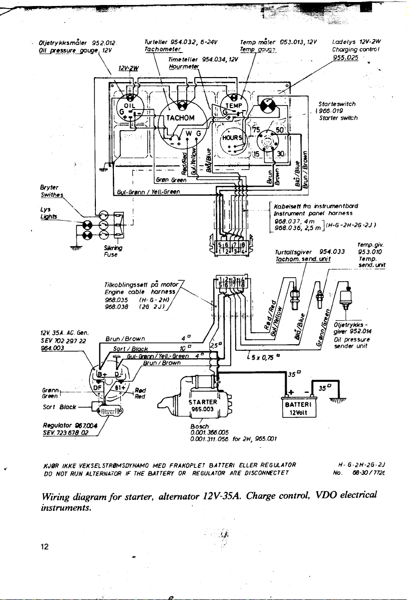
Wiring diagram/or starter, alternator 12V-35A. Charge contral, VDO electrical
instroments.
12 .'
.!:I;.
.
g

,
.
INSTRUMENT CONNECTIONS
Tachometer (Mechanical Drive Type).
1. Unscrew tachometer drive .~--~_. ~ end nut (1). ~--.l_,~~ I
2. Insert hexagonal part of I. 2 1
tachometer drive screw(2)
through centre of axial
hearing housing to engage F. 10
with hexagonal socket (3). Ig.
3. Couple up tbe tachometer
drive cable and tighten tbe
.. cablenut(4).
Avoid sharp bends in tbe drive cable. Minimum radius: SO cm (20 in.)
Drive cables longer than 1.5 m (5 ft.) should be secured witb clips.
Tbe water temperature gauge is connected to tbe temperature sensor fitted in tbe
port after wall of the cylinder head.
Tbe oil pressure gauge pipe is connected to tbe nipple on tbe starboard side forward
of the governor cover.
Tachometer (Electricallmpulse Type - af ter August 1977.)
. ~
1. Fitimpulse senderunit(A) ~, ~p
Fig. 11, in flywheel shield of n --=--;~ ,~. ~
main hearing housing. Adjust f'
'distancebe~eensenderpoint, C "-~~~1C" ~ 1.[Jl~.)
and starter nog 1.5 mm(1/16 ')
See wiring diagram page 12. \."". ~ ,').G, ( ') ~~
0' Water Temperature Gauge ~;:s;, "- ~~
Temperature sender unit (B) is \:;: '"
fitted info cylinder head. ':j \
Oil Pressure Gauge (Electrical or MechanicaI). Fig, 11
Sender unit (C) or gauge pipe is connected
to the nipple on starboard side of crankcase.
\ . 13
~~~- .
\ ~ ~ ;-"":. ~l!J G 2. Connect wires to tachometer. ~ ~ .
~C _~,_I~ !
~I. \ ,I
~,. -
I~t~' (Electrical) c~ I\~

-
F. Checks
E. Adjultmentl
~ ;', ~
44 Check Injection pump . 44
43 Reverse gearbox . 43
42 Change propeller shall driving block . 42
41 Clean crankcase sump and strainer. 41
40 Tighten down cylinder head . 40
39 Check or change governor springs . 39
38 Adjust decompressor vaJve . 38
37 Adjustairandexhauatvalveclearances. 37
36 Adjust clutch. 36
35 Adjust idle . 30
.. 34 Adjust V.belt (impeller pump) . J4
33 Adjust V.belts . 33
32 Check heat exchanger ! . 3Z
31 Changeimpeller '. . 31
30 Checkzincanode . ~
29 Check thermostat (1974 model) . 29
28 Check thermostat and thermostat atralner . ~
27 Check diaphragms In double water pump .. ~,
26 Change water pump diaphragm . ~
25 Check water pump dlaphragm . 25
24 Checkwatervalve . 24
23 Check cooling water level. 23
22 Drain coollng water .. 22
D. Coollng woter ;
21 Check or change 1111 pump dlaphragm , . ~1
20 Clean lill pump strainer 2g.R.,. . . 2IJ
19 Clean injector nozzles I . 19
18 Bleed luel system . 10
17 Changeluelfilterelement . , 17
C. Fuel IYltem
~'
16 Grease gearwheel bllge pump . lti
15 Greaseruddercontrols . '"
14 Greaseremotecontrolcompo~nts I . 14
13 Greaseremotecontrollever ~I~~ . 1"
12 Grease starter plnion I' ... . 1~
11 Greasegearboxseal . 11
10 Grease pitch control ,. 10
9 Grease inboard stulling box. ~
6 Grease propeller. 8
8. G","lng
7 Change lubricaling olliliter .
6 Change gearbox 011 . ti
5 Change cluch 011 ."
4 Check oliln clutch . 4
3 Change engine oil . "
2 Checkgearboxoillevel. ~
1 Check engine oi! level. 1
A. Lubrtceling Dil
running hlS running hlS running hrsrunning hn running h.. running hrs equire<
Every 5 Every 25 Every 100 Every 300 Every 600 Every 1200 As
D811y Weekly At "8lt8nnu8l1y 2 V_rIy
CHECK POINTS
J.'f!r:I:.'II1.'1~' Maintenance schedule tor types 2H-2HSP-2HG
I

"; ';
'"
CARE AND MAINTENANCE
To achieve good results in operation, it is important to give the engine the attention
recommended. Tbe following section includes general guidance, descriptive notes
and sketches to assist in routine maintenance.
If the specified maintenance is carried out correctly and at the recommended
intervals, engine deterioration will be minimised and optimum performance will be
ensured.
MATERlALS '. Cc,
" ;,
A. LUBRICATING OIL SYSTEM
'" Tbe lubricating oil system is pressur-
ised, the oil being pumped from tbe .
sump oil filter (1) via tbe oil pump (2)
(gear pump fitted inside pump housing) and, under pressure, to the fu1l
flow filter (3). Oil channels in tbe
crankcase/ main hearing housing provide lubrication for crankshaft main
hearings and connecting rod hearings.
A pulsed oil flow is also fed via the
camshaft (5) and the pipe (6) to tbe
~ rocker arm hearings before being re-
turned to the sump.
. Tbe oil pressure is limited by the oil
pressure relief valve (4) fitted behind Fig. 12
tbe oil filter (see Figs 12 and 18). Tbe
oil pressure is indicated on the
pressure gauge (7).
LUBRICATING OIL
Tbe engine oil should be checked daily before starting. Tbe dip stick is located in
the governor cover and bas two level marks. Tbe upper mark indicates tbe oillevel
. when the sump is fu1l (4Iitres). Tbe level shouJ.d never be allowed to fall below the
lower mark.
To ensure effective lubrication and long lasting engine cleanliness, it is important to
use an approved oil to tbe correct specification.
API-SERVICE CO (Previous nomenclature: Service OS-Series 111):
15

-'
The manufacturer recommends the use of mono:-grade oil (SAE 10. SAE 20 or
SAE 30.) Multi-grade oil (SAE 10/30) should not be used.
LUB.OIL VISCOSI1Y AT AMBIENTTEMPERATURES SUMPCAPACITY
QUALITY Below +IO"C +10to +30" C Above +30°C 0il01ange Incl. OilFilter
. 4litres 4.5 litres
Service CD SAE 10 SAE 30 (7 pints) (8 pints)
The following makes and grades may e used (as may other makes of corresponding
quality): r-O
HP Energol DS3 Mobil Delvac 1300
Chevron Delo 300 Motor Oil Ocean Diesoline 3
Castrol Devsol RX Super Reginol CD-SD
Essolube XD-3 Shell Super Marine Oil
Fina Solna S3 Texaco Ursa S3
Gulfpride Series 3
IMPORTANT:
If the engine bas been wholly or partly immersed in
water, all oil in the crankcase and clutch housing (or
(SO°F) ( (86°F)
~O-~
Use the same oil for clutch/ gearbox.
~gearbox) must be changed immediately.
.1
1). DIPPING ENGINE OIL (Daily):
1. Withdraw dipstick (1) and wipe clean.
2. Insert dipstick fully and withdraw to read oillevel.
Repeat if necessary .
3. The oillevel must never he allowed to fall below the J
0( lower mark on the dipstick. If necessary, top up so ~o
that level is at upper mark. ""'
4. Replace dipstick and screw home.
If the engine is mounted at an angle exceeding 8
degrees the oillevel when the sump is full (4 litres)
wililie above the upper mark on the dipstick. The .
oillevel should normally lie between the two marks. Fig. 13
16

"" 2. DIPPING GEARBOX OIL (Weekly):
1. Unscrew dipstick ("QIL" cap) (1) and' I
wipe clean. 7 -r~'"
2. losert dipstick fully (to fust thread) and
withdraw to read oillevel.
3. Top up if necessary and replace "QIL"
cap and screw home.
Note that dipstick reading is dependent on
engine mounting angle.
.. Fig. 14
3. ENGINE OIL CHANGE (at least annually):
The crankcase sump holds 4 litres of oil and this
should he changed while it is still warm.
~ 1. Oean round "QIL" cap (1) and unscrew cap.
~"
~ 2. Hold oil removal syringe (2) with its flexible tube
; down in the sump. Pump oil out and into an emty
:: cao.
=- 3. Place a mnnel in the filler opening and fi11 with 4
litres of oil of the correct grade. (See page 16.)
4. Screw back the "QIL" cap and replace the dipstick.
5. Start engine and check oil pressure.
I- ~()
4. CHECKING OIL IN CLUTCH (at least annually)
... The clutch housing holds 0.5 litres of lubricating oil.
1. Unscrew clutch housing cover (Fig 16 Item 1) and
check oillevel in the clutch. Turn the engine over Fig. 15
and check that the clutch reaches into the oil. Top
up if necessary .
2. Check condition of cover gasket and replace cover. :.\
~~~
~ 17

5. CHANGING CLUTCH HOUSING OIL (at least annually):
re clutch tension adjustment.
I
6. CHANGING REVERSE GEARBOX OIL (at least annually):
, 1. Unscrew dipstick. Hold oil removal syringe
. (2) with its flexible tube passing through
1. Unscrew clutch housing cover (1). Hold oil
removal syringe (3) with its flexible tube
down in the clutch sump. Pump the oil out
and into an emty can.
2. If the oil is thick or dirty, wash out the
clutch housing with fuel oil and carefully
wipe dry before refilling with new oil.
3. Fill with 0.5 litre clean lubricating oil
through cover opening. Do not add extra
oil. If the clutch slips, see Item 36 tor
Fig. 16
Q~~.tfai
The reverse gearbox holds 0.5 litres of
lubricating oil.
the dipstick opening and down into the reverse gearbox sump. Pump the oil out and
into an emty cao.
. 2. The oil catl also be drained by unscrewing
the magnetic plug in the after end of the
reverse gearbox. Always remove the magnetic plug and clean before replacing.
.- 3. If the oil is thick or dirty, remove the gear-
e,_" box housing cover and wash out the gear-
:: box with fuel oil and carefully wipe dry
before filling with 0.5 litres of clean lubricating oil by way of either gearbox housing
cover opening or dipstick opening.
Fig. 17 4. Replace dipstick.
18
. Cc
',,';;P

..
;~)~.";
.'
7. CHANGING ENGINE OIL FILTER (at least annually): ':,,;j~"'é}-)
The oil filter is located on the
outside of t~e crankcase on the t' 2 3 ~.i'
left hand slde. It should be
changlng the engme oil. (. ~ i
1. Loosen the oil filter (1) with a ) 1
spanner or hammer a screw
driver through the filter to '~ 4~
facilitate loosening. Unscrew ~Ii
and dispose of both filter and
rubber gasket.
~ ' - .-#
~~~~ chang~d in co~junc~on with ~
. 2. Before fitting a new filter -
(FRAM PH9A or MANN
W9.20/7), dry the sealing Fig. 18
face of the filter holder using
a clean rag.
3. The new filter gasket (2) is lightly coated with oil and fitted into the filter seating.
Screw on the filter by hand until the gasket is touching the sealing face.
Tighten by hand ODe further hal/turn. Do not tighten using tools. (Item (3) is the
~ oil pressure relief valve.)
~ 4. After filling with oil (4.5 litres including filter), start the engine and check that
I~ there is nó leakage at the filter seal.
B. GREASE
The engine, and remote control equipment if fitted, have greasing points that
require regular attention.
The following types of universal grease cao be used for all greasing points (engine
, propeller): .
. Castrol Spheerol AP2 Gulfpride SF " ~
BP Energrease LS-EP Fina Marson EPL ._~
... . - "
Chevron Dura-Lith Grease No 2 Mobilux 2 or Mobilplex 47
Esso MP Grease Beacon EP2 Shell Alvania Grease En "',
Texaco Multifak EP2
19

8. GREASING OF PROPELLER (Daily):
WPropeller and stern hearings are lubncated by screwing
. up one turn on the grease cup (1) after every 5 hours run-
ning or daily.
Lf-lfljl. When operating in sandy waters it is important that the
I '/~ 1 controllable pitch propeller should be greased regularly
1 and liberally.
I
~/' IMPORTANT:
11 1 2 If the controllabie pitch propeller controls are noticeably
,;1 / heavier when the boat bas been out of use for rome time,
ïtt= : .. 3 the reason may be that the propeller grease bas been
\ I. I washed out by contarninated sea water or strong current
. - I. etc. In such cases the propeller should be greased with
I special stern grease.
.oR. Fig. 19 should only be used for propellers and stern hearings.
9. GREASING OF INBOARD STUFFING BOX (Daily).
~ .,'/ . '.. The stuffing box bas a gland (6) packed with
(i . ~ .~allow. The gland should only be tightened just
. There are many good quality stern greases but they
.:'~.::::: 5 running or daily.
.'.'::".~
~.- ~ufficiently to prev~nt leakage. Excessive tighten-
- 0
~' The tallow packing should be changed when the
oe mg causes overheating and wear on the shaft.
Fig. 20 does not seal properly.
Note:
One turn of the grease cup (5) after every 5 hours
gland movement is fully taken up or if the gland
20
i --~ - "- ,-'- --~

10. GREASING OF PROPELLER CONTROL (Weekly):
The engine, including clutch/
grease ~n lubrication (see lig) I
2H-2HSP. -""
1. Sliding bolts: t 2
2 shots with grease gun.
2 shots with grease gun.
3. Propellercontrol hearing: -
2 shots with grease gun.
!;: 4. Propeller controllever:
2 shots every 50-100 hours running.
S. Qutch lever:
2 shots every 50-100 hours running. Fig. 21
11. GREASING OF GEARBOX SEALS (Weekly): :
The rear sealing rings (6) should be I ti
lubricated weekly, 2 shots with a ~
grease ~n or until grease emerges c
round the wear ring. '
~propeller control, bas 5 niples lor "
\\2. Oil Seals: t:
IMPORTANT:
If there is so much water in the boat
that it covers the sealing rings, the
boat should be pumped out before
operating the gearbox.
Fig. 22
21

""CC,ccc, .
GREASING OF AUXILIARY EOUIPMENT .'
12. Greasing of Starter Pinion (as required):
The starter must not be subjected to
water spray off the starter ring.
(See page 11.)
If the bendix pinion becomes rusted,
~ the starter should be removed (or
I sprayed with oil) and the starter pinion
~ r greased.
'f4;C-L-~ 1. Disconnect the electricalleads and
.1 Q rr:" unscrew the starter hom the engine.
. . 2: Insert a screwdriver (1) behind the
3 2 1 pinion (2). Lever the starter pinion
out while turning it clockwise.
Fig. 23 . 3. Apply grease (or lubricating oil) to
the shaft (3) and the starter pinion.
Turn the pinion to and from until it
moves freely in its track.
4. Assembie and fit the starter. Reconnect electricalleads and battery.
13. Lubrication of Remote Control
Lever (as required):
Apply oil or grease reguiarly to the rack
drive as shown in the figure.
Fig. 24
14. Greasing of Remote Control
(as required):
! The drive block on the end of the telescope
tube is free to move on its securing bolt
and this nipple (1) should he greased regu~arly to ensure the easiest possible manoeuvr-
fig.
Cables for propeller pitch, clutch or reverse
gearbox control, redder control cables and
cable guides should he coated with grease
during installation.
Fig. 25 J. Suitable grease: Esso Beacon ]00 EP.
22

15. Greasing of Rudder Controls (as required):
SABB rudder controls incorporate 2 grease
nip'ples. ~e is on the un?erside of th~ Ope- b ~ ~
ratIng Umt and one (2) IS on the umversal 0"",- "'
joint. Both points should be greased regu- -
larly.
Gearwheel Bilge Pump
The pump is driven by a V -belt (L T 28) on the outermost track of the flywheel
drive pulley. The V -belt is tightened by slaékening screw (1) and tuming the whole
pump. Re-tighten the screw securely.
Engaging anddisengaging (handle 5) must onIy be performed at low engine speeds
to avoid wear on the driving pulley or damage to the drive key.
Ensure that the pump is engaged or disengaged fully.
The drive key (2) can be replaced by unscrewing the set screw (3) with a 3/8" socket
spanner. Anew drive keycanbe made from 1/4" x 1/4" x34 mm mild steel.
If the pump is not working properly or if it needs excessive priming, tros may be a:n
indication of intemal wear causing leakage between suction and pressure sides of
~ the pump. In tros case the end clearances of the gearwheels must be reduced by
~ filing the pump housing flangeuntil flush with the gearwheels.
.:~~~~~~~~ ~ )
Fig. 26
i Useathingasket(O.15-0.20mm)
5 &'
16. Greasing (as required):
Remember to lubricate regularly using the
grease cup ( 6). The coupling sleeve and
coupling bolt also need greasing occasio-~; -
nally. "',
The ~arings are sealed and do not require
greasmg.
Use the drain cock (4) to drain oft the water" 4
in cold weather.
Keep the strainer clean. 1 2 3 Fig. 27
~j;;;'
23

r.' . ,,-, C. FUELOIL
"; Use only gas oil (auto diesel).
I The oil must be absolutely clean and should contain as little water as possible. This
is a good insurance against fuel pump or injector nozzle problems.
; Drain of! water and sediment trom the fuel tank regularly, at least once tor each
cî time the tank is ftlled. Use a straining cloth, cotton cloth or nylon stocking over the
tunnel when filling.
Make sure that the tank is never run dry. If this does happen, the fuel system must
be bleed. It is not necessary to close the fuel tank cock because leakage is not
possible provided that the fuel plpes are intact.
If the engine is started with the cock closed it will stop after a few minutes and
bleeding will be necessary .
.
2 " 5 3 (At least annually):
17. CHANGING FUEL OIL FILTER
1. Oase the fuel tank cock.
2. Unscrew the fuelleak-off pipe (1), fuel
bases (2 and 3) from the filter cover.
Loosen screws (4) and lift off the filter.
3. Unscrew the central bolt (5) and lower
filter bowl (6) and element (7).
Remove and dispose of used element
(7). Oean filter bowl and insect new
element.
(BOSCH FJ/SJ 27511 457431324)
4. Ensure that the rubber gasket (8) is
28 correctly located in the filter bowl
seating and tighten the central bolt (5).
Fit the filter to its bracket and secure
the fuel hoses and fuelleak-off pipe.
5. Open the fuel tank cock and bleed the
fuel system. See Bleeding page 25. -
Tighten central bolt.
24
..

18. BLEEDING THE FUEL SYSTEM (as required).
1. Check level of fuel in tank and see
that fuel tank cock is open.
2. Bleed filter by looserJng nut on fuel
leak-oH pipe (1) three turns.
Operate hand pumping lever (Fig
32, item 6) on fuellift pump until oil
escaping trom filter is tree of bub- \ - I.
les. ~, --~-
pump by slackening banjo nipple -~\ C~
hand pumping lever until the \
escaping oil is free of bubbles. Fig. 29
4. Retighten banjo nipple plug securely, making sure that the base is not kinked
during tightening.
NOTE: Never unscrew the injection pump delivery valves (3).
S. Open decompressor valve and set govemor control lever to fun speed position.
Turn the engine over (either by hand or using the starter) until noticeable
'"
"knocking" can he feIt in the injector pipes coincident with each injection.
- ,
~~1 3. Bleed fuel hose (2) to injection' "
)plug (4) three furns and operating ,
t The knocking indicates that the system is free of air and that the nozzIes are
t~ working.
I
,
~~
"f ..
,
~r',! " .
. u~" ,
; ",
! .. i
; i:"-..
~~c-~c:;.
25

"~~"'."
19. CLEANING THE INJECTOR NOZZLES
(As required):
Impurities in the fuel, or fuel containing
6 5 water, can lead to poor atomisation in the
\~ . , .! nozzIes, spray distortion or post-injection
'" --3 black smoke in the exhaust and be
leakage. The engine may knock, make
~ difficult to start.
i .~~ If this is the case, the nozzle must be
~-,:,:; ~...1 2 cleanedorrenewed.
7" \ \\ \ cf. / 1. ~~screw inj~tor pipes (1 and 2) fr°t;n
\ ' , IV"~!~--~ mjector bodies (6). Unscrew banjo
\ \ \ \ !~~ ///1 nipp~e plugs (4) and remove fuelleak-
~/ f offplpe(3).
'\ \6'\,
\ ,,\~&\~ ~ T 2, 2. Remo~e.injector h?dy balts and wit.h-
1 ~p // " '/ draw .injector bodies tor further dis-
~~ \... _/ mantlmg.
~ -.. -' ff7J;:;:' The injector body is best held upside
Fig. 30 upside down on the cylinder head and
3. The nozzIe sleeve (7) is unscrewed and the nozzle removed. The needle (11) should move freely in the
nozzIe. Never touch the needle itself but hold it by the
~~- - 6 cylindrical spigot. Wash all components in clean ~el
U- oil. Any particles adhering to the nozzIe end or to the
needie should be removed using a small piece of wood
i . or matchstick.
~ 4. Re-assemble the injector body exactly as shown in Fig
~ 10 towards the spring.
f\ Remember to insert the nozzIe joint washer (13) before
\J I I positioning and securing the injector body.
9 31, ensuring that item 9 is fitted with its shorter spigot
down in a vice but it may also be placed
secured by means of its balts (5).
~ 5. Fit the fuelleak-off pipe. The injection pipe Duts should
0--12 be screwed up lightly. Turn the engine over with gover-
~ nor control lever set to fuIl speed (decompressor lever
'j.:~;, ~"""';
: Fig. 31
26
,,--~
7 open) untiloil sprays out.
0 13 "%,- Ti ghten Duts securel
,
c'. ;-~~- ...
"--.
y.

20. CLEANING OF LIFT PUMP STRAINER
(When renewing fuel oil filter element):
<"
.c hand side of the crankcase and sup- 1- ~
The lift pump is positioned on the left \!I
plies fuel to the filter . ~
1. Oose fUel tank cock. 8
2. Unscrew central bolt (1). Remove
9
cover. Remove and wash out the
strainer (2).
3. Replace strainer and fit cover, en- 3
suring that the gasket is properly in
position. Tighten central bolt se- I. /'
I curely.
4. Open fuel tank cock and bleed the
system. 5 .
i
6
7
~
Fig. 32
' 21. CHECKING OR RENEWING LIFT PUMP DIAPHRAGM (as required:)
1. Oose fuel tank cock.
2. Unscrew fuel pipe (9) and fuel hose (8) from lift pump. Remove securing screws (7) and withdraw lift pump from engine. Oean strainer as in item 2
. above.
3. Loosen and remove upper body (3) or lift pump. Check that the two valves and
the diaphragm are in good order. If the diaphragm needs renewing, hold the lift
~ pump arm and press down on the diaphragm while at the same time turning it a
quarter of a turn to free it for removal.
Ensure toot the spring underneath the diaphragm is properly in place before
'" fitting a new diaphragm.
4. Check that the air vent (5) on the underside of the lift pump body is open.
(Prevents fuel being pumped into the engine if the diaphragm is damaged.)
"" 5. Re-assemble lift pump, fit to engine (check that gasket is in good condition) and
J
~. secure.
;
, Refit fuel hose and pipe and bleed the system.
27
,
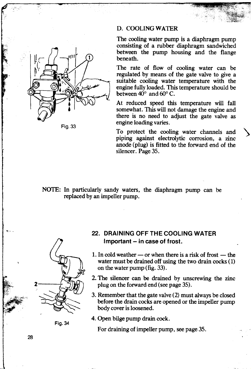
D. COOLINGWA1ER
The cooling water pump is a diaphragm pump
consisting of a rubber diaphragm sandwiched
between the pump housing and the flange
beneath.
The rate of flow of cooling water can be
regulated by means of the gate valve to give a
suitable cooling water temperature with the
engine fully loaded. This temperature should be
between 40° and roo C.
At reduced speed this temperature will fal!
somewhat. This wi1l not damage the engine and
there is no need to adjust the gate valve as
Fig. 33
engine loading varies.
T.o. protect. the cooling .water c~annels a.nd ')
plpmg agamst electrolytic corrOSlon, a Zlnc
anode (plug) is fitted to the forward end of the
silencer. Page 35.
NOTE: In particularly sandy waters, the diaphragm pump can he
replaced by an impeller pump.
". 22. DRAINING OFF THE COOLING WATER
Important - in case ot trost.
1. In cold weather - or when there is a risk of trost - the
, water must he drained off using the two drain cocks (1)
on the water pump (fig. 33).
2. The silencer can be drained by unscrewing the zinc
'-~ 2 plug on the forward end (see page 35).
-,
:;: ""f"""~"
;~ ~ before the drain cocks are opened or the lmpeller pump
~.~ ".'.' '- "- body cover is loosened.
':-,'~ .
~ 3. Remember th~t the gate valve (2) must ~ways be closed
. 4. Open bilge pump drain cock.
Fig. 34
For draining of impeller pump, see page 35.
28

FRESH WATER COOLING (Closed System)
The fresh water tank (2) (1974 1
model) is separate from the ---7 - - I
silencer and is mounted on top 2 - - . I
of it.
The thermostat (3) is located in
the silencer where it adjoins the
fresh water tank.
The keel cooler (4) is mounted
on the underside of the huIl.
If preferred, it is possible to fit
an intemal heat exchanger in
place of en extemal cooler.
). This requires a separate pump.
...
"' . through the system until the
. ~ tank is full. Check that there -~::
~
~ \ are no leaks in the system. Fig. 35
See page 30.
When first starting, fill the tank
with clean fresh water, or a
water / antifreeze mixture, via
the filler with pressure cap (1).
Top up as the water disperses
~
.~-
Operation
Until the cooling water bas warmed up the water flow is through the silencer cooling
jacket channels, out of the rear of the silencer and via the by-pass pipe back to the
water pump.
When the engine bas warmed the cooling water up to 55° C, the thermostat begins
to open and divert part of the water via the fresh. water tank to the extemal cooler
(or intemal heat exchanger where it is cooled before once more entering the water
pump).
- When in operation, the termostat will automatically distribute the cooling water
between extema! cooler and by-pass pipe, thus maintaining the cooling water
'" temperaturebetween55° and 75° C. (130-170° F.)
In case onncorrect operation (water temperature too high or too low) check:
.*' .
~ 1. Waterpumpdlaphragm Page 32
~ 2. Watervalves Page 31
~ 3. Termostat Page 34
4. Too little water in the tank Page 31
,\
1"'c
29

5. Keelcoolerdefectiveorpainted "",,"""""""""""'" Page 29
6. Heat exchanger. . . . . . . . . . . . . . . . . . . . . . . . . . . . . . . . . . . . . . . . . . ., Page 36
7. Cracked cylinder head causing compression leak into cooling
jacket. Symptom will be heavy bubbling in water tank. Most
easily confirmed by letting the motor cool and then letting it idle.
Winter Use
For use in winter the system should be filled with an approved make of glycol antifreeze. With standard piping the system holds approximately 5 litres. The
addition of 1 litre antifreeze (4 litres water) affords protection down to -80 C
while 1.5 litres of antifreeze will protect down to -150 C. Flush the whole
system with water before filling with antifreeze solution. After filling, run the engine
for 3 minutes to ensure thorough mixing. When using glycol antifreeze it is not
necessary to drain the system before or after winter use (or laying up) provided thai
the coolant remains clean and tree of rust flakes. If this is not the case the system
must be flushed through.
SEA . Fresh Water Cooling
WATE .
PUM
5 water may be discharged
CG wlth Heat Exchanger
6 .
\ The lmpeller pump (4)
\ pumps sea water through
the heat exchanger (2)
where the engine fresh
water is cooled. The sea
overboard via the exhaust
,,\ hose (wet exhaust).
NOTE:
".--
2 drained trom heat
3 '
-G:.~ ~",,:~~ Fig. 36 ~:~~d ~; ~~~n;~~ be
When there is a risk of trost
the sea water must be
exchanger and im peller
.. FRESH WATER the pump housing cover
slightly. The heat exchanger
~ SEA WATER may be drained by slacking
off the drain plug (3). Oose
the gate valve (1).
30
,
"-'"
,-" y"

23. CHECKING COOLING WATER LEVEL (Weekly):
A weekly .-;:heck is generallyadequate but if the engine is being run continuously in
warm weather, a daily check may be necessary. 1
1. The engine cooling water must have cooled
down sufficiently for the fresh water tank to
be touched without discomfort.
2. Open the pressure cap carefully. Beware of
any water spraying out since this can scald.
3. Check the level and top up if necessary to
bring the water level up to the lover edge of
the filler neck.
.. If the system contains anti-freeze, it should be
. topped either with a solution of the same _n
strength or with neat anti-freeze. (See page 30.) ~
Fig. 37
J,. 24. CHECKING THE WATER VALVE (as required):
i The wa~er valve housing (4). is mou!1ted on the cooling water pump ?n the left of
, the engIne. If pump effectlveness IS reduced, the cause may be dirt under the
'\ valves(3).
vi ~
; 1. Oose the gate valve. 1 ~
Open the drain cocks (9). 2-8
2. Undo the suction pipe connection 3 ~
to valve seat (5) and unscrew the
valvehousing(4). 1.'-
3. Holding the valve housing in a vice,
unscrew the plug (1) and the valve 2---e'
~ the valves. Renew valves and springs 3 =Ij
~ if necessary ..
* moval of plug and valve seato
'" If the valve seat is scored it can be 6 7 8 9
c;.
,~i 4. Before securing the valve housing in position between clamp (7) and water pump
'~ housing, check that the gasket (8) is in good condition.
seat (5). Check for any dirt under ~
secured to the water pump for re- ~
rubbed carefully over a fine file, Fig. 38
rotating the seat while doing SQ.
~The housing may alternatively be 5 c,
~ 5, Fit the suction pipe. Oose drain cocks and open gate valve.
i 31

-- 25. CHECKING WATER PUMP DIAPHRAGM
(At least once annually):
1. If the cooling water level (fresh water cooled
ff~ engines) falls abnormally, or if the pump cir-
I f culation is irregular(sea watercooledengines),
V the cause may be a detective diaphragm.
i 2 2. In the case of both sea water cooled and fresh
I water cooled engines, this may easily be
t:1 checked by slipping a piece of paper (3)
. ~ underneath the pump housing and flange
"\ while the engine is running.
' , "'" 3. The pump flange (1) bas drain holes (2)
1 &~ // underneath and, if diaphragm is detective,
3 ~ ..~ water will drain out and wet the paper.
Fig. 39
26. RENEWING WATER DIAPRAGM
(as required). 1. Oose gate valve. Open drain cocks (7)
and undo the pipe connections. In the
. drain oH the anti-freeze into an emty
.., against the diaphragm.
. .. / :?" Screw firmly home.
" / r- 5. Fit the pump housing and close the
.. drain cocks. Fit the pipe connections
2 7 3 5 1 and open the gate valve. In the case of
Fig. 40 system adding anti-freeze as required.
32
case of fresh water cooled engines,
can.
2. Unscrew the nuts (3) and withdraw
pump housing (2) and valve housing to-
gether.
3. Undo the diaphragm screw (4) using a
good screwdriver, remove diaphragm
washer(6), andrepiace detective diaphragm (5) with a new one.
4. The new diaphragm is fitted with its
marked side facing inwards. The diaph-
ragm washer is fitted on the inner side
of the diaphragm with its convex side
fresh water cooled engines, fill cooling
/ ,.:\"
, '

27. CHECKING DIAPHRAGMS IN DOUBLE WATER PUMP
(Ay least once annually):
~ Fresh water cooled engines are usually fitted with a double water pump (wet
" exhaust). The stand;trd pump (outermost) circulates the fresh water and the extra
pump (nearestengine) cools the rubber exhaust base.
. .
- 1. Remove pressurecap, open dram cocks (6)
f ,.rr'r2. Oose gate valve tor extra pump /'
/(
~:) ~~ ~~~p~ pipe connections 8 9 ,10 ,'1 -I Il ~
~off anti-freeze into an emty can. "',f..-"
3. Undo securing ~lts(7) and with-
draw pump housmg(8). e ( v ~ :::---9
~ r~ ,'I ~ ./' "'-
"" diaphragm washer (11). Undo ::->
.'" washer (2).
"" 5. Check bath diaphragms and renew if necessary .
.\
~ 7. The large diaphragm (3) is positioned in the pump housing seating and the
~ bly is positioned against the pump flange (1), centred and secured using
~ thefixingbolts(5).
4. Unscrew the diaphragm screw %k ~
(9) using a good screwdriver, re- ; -< '\ ,~
the securing balts (5) and with- ~~
draw pump housing (4). Remove 7 6 5 I. 3 2 1
large diaphragm (3) and inner Fig. 41
Assembly:
6. Diaphragm (10), with its marked side facing inwards, is fitted onto the diaph-
ragm screw (9). Then fit the diaphragm washer (11) with its convex side against
the diaphragm.
diaphragm screw, with diaphragm and washer, is insérted trom the outside. The
diaphragm washer (2) is fitted onto the end of the screw (9) and the whole assem-
8. Tighten the diaphragm screw (9) securely, fit the water pump and re-make all
pipe connections. Oose the drain cocks and open the gate valve on the extra
~~~d\'~~ (~~~?'-
~~' '""'
1move the diaphragm (10) and
:. pump. Top up the fresh water system.
~
. .
j '"""
~ .cc~'-
.
-~~.,,~""~"""~"'c"cc~-~""
33

'.
:
,
i
, 28. CHECKING THERMOSTAT, 1. Remove pressure cap (1) and open
CLEANING THERMOSTAT drain cocks on water pump.
STRAINER 2. Drain oH anti-freeze into an emty
(At least once annually): caD.
1 6 "J 3. Remove thermostat housing (2) and
, "" ~ 60° C. The thermostat should now
~ """ i 3 open and close again when placed in
, ~ cold water.
~ j' 4. Remove thermostat cover (5) and
~.. ~ . wash out strainer in gasket ( 6) .
, I , Thermostat and strainer caD be
I !I~ 5 washed in white spirit if necessary.
~I ~ Ifc ~ If the thermostat does not function,
~ the installation can be run witbout a
~ lt' 2 hot water at a temperature above
! withdraw thermostat (3). Place it in
",Cc
" / thermostat provided the by-pass
v' pipe in blanked oH.
/î 5. Re-assemble. Ensure that the cor-
Fig. 42 during topping up. Oase the drain
rect amount of anti-freeze is added
cocks.
8--,--9 10 7
29. CHECKING THERMOSTAT 8 '~
11 1. Disconnect the return hose (11) trom the after ~"',.~ -
end of the fresh water header tank. I . .-;--
2. Remove pressure cap (7) to allow air into the ~ i; I
tank and drain oH the anti-freeze into an ~
empty caD via the nipple at the after end of
thetank.
Undo the Duts (9), lift oH the fresh water
tank (10) and remove the thermostat (8).
Place it in hot water at a temperature above
60° C. It should now open, then close again
when placed in cold water. If necessary, wash
the thermostat in white spirit.
If the thermostate does not function, the I
jJ(1974 Model): ~~~:::~J-?> - ~
~installation can be run without a termostat
provided that the by-pass pipe is blaked oH.
4. Re-assemble. See item 5 above. Fig. 43
34
'~:l~?~(c
':~
,i"t' '
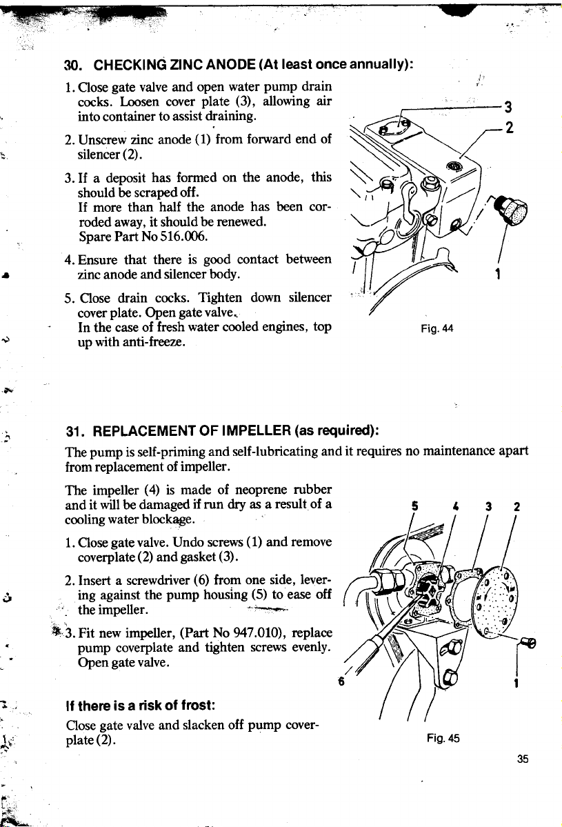
30. CHECKING ZINC ANODE (At least once annually):
1. Oose gate valve and open water pump drain :
cocks. Loosen cover plate (3), allowing air ' 3
into container to assist draining., ~~~
" 2. t!nscrew zinc anode (1) from forward end of ~~
;: sllencer(2). ~"~~ ~
3. If a deposit bas formed on the anode, this ~ ~ ~
shouldbescrapedoH. ",~
If more than half the anode bas been cor- . cC
roded away, it should be renewed. "'- I III~» I ,/ '~;
Spare Part No 516.006. '-""" d ~
.. zmc anode and sllencerbody. 1
5. Oase drain cocks. Tighten down silencer "
cover plate. Open gate valve,
~ up with anti-freeze.
,..
,:, 31. REPLACEMENT OF IMPELLER (as required):
In the case of fresh water cooled engines, top Fig. 44
The pump is self-priming and self-lubricating and it requires no maintenance apart
from replacement of impeller.
The impeller (4) is made of neoprene rubber
and it will be damaged if run dry as a resultof a 5' 2
cooling water block~e.
1. Oose gate valve. Undo screws (1) and remove
coverplate (2) and gasket (3).
2. Insert a screwdriver (6) from one side, lever- ~
.
~~~~~)""'" r 2
~Il" // /'1
i,
~'; ó ing .against the pump housing (5) to ease oH :';
. thelmpeller. "'~. ':"
" , -ti
.,3. Fit new impeller, (Part No 947.010), replace '
. pump coverplate and tighten screws evenly. ~
. Open gate valve. I
6 1
"l If there is a risk ot trost:
, Oase gate valve and slacken oH pump cover-
l'" plate(2). Fig. 45
c'
t~,.'
~
c~
35

...' ,,:t(~
32, CHECKING HEAT EXCHANGER
An apparent failure in the cooling water supply (rising engine temperature) that
, piping, may be due to an end aperture blockage in the tube cooler.
I Checking tube cooler: Fig. 46
i If the level falls abnormally, the tube cooler
cao not be attributed either to a faulty impeller or to air in the pump or associated
Checking:
1. Oose the gate valve. Open drain cock (1)
to drain sea water from the tube cooler.
2. Remove suction hose and end cover (3).
Remove any waste material (grass etc) that 2
may he blocking the cooler end aperatures
and preventing effective flow through the
cooler.
3. Re-assemble in reverse order.
6 5 4 3 1
should be checked. Remove the entire heat
l exchanger.
i 4. Remove the covers (3) and gaskets (4) from both ends of the heat exchanger.
5. Place a piece of wood over ODe end of the tube cooler (5) and tap carefully to
remove cooler from its housing ( 6).
6. Insert replacement cooler, fit end covers and re-connect hoses. Top up engine
fresh water cooting system.
.. . ~"'V-;J1. dj" ~"i',~
,-,,' 1 ~:~ ~\'"' ;~f?
"'.
'é:
I'" 36 ,:;!";
f
I. c
.",. """',~c

E. ADJUSTMENTS
r'
;t" Every 100 running hours: 1'" ~~À~
33. ADJUSTMENT OF V-BEL TS (Alternator)
~. drive the altemator and maintain the battery 2 ~ ~,~
charge. ~'. '-
Therefore check the V-belt tension regularly
(initially after 2S running hours), and parti- 3
cularly if charging is not satisfactory. 4
1. Slightly loosen the securing bolts (2 and 3) 5
and slacken oH the tensioning bolt (5).
.j-'- 2. Tension the belt (6) by moving the alter- 6
nator (1) upwards. Tighten the tensioning
bolt (5).
.; 3. Check the tension. When the tension is Fig. 47
cÇ>rrect, it should be possible to deflect the
belt about 3 mm using thumb pressure at
.., pulley.
a point midway between flywheel and drive 2 1
~ . 4. Tighten bolts 2 and 3, check that tension- :---
-" ing bolt (5) is tight. (V-belt: Rofan 3915.)
Direct Current Generator ~~
1. Slightly loosen securing nut (1). &
wheel (2) clockwise until the desired tens- 3
ion is achieved (see item 3 above). ..)
3. Re-tighten securing nut.
~ (V-belt: Rofan 3915.)
.al1=~-~; ~..:\ ~~\\
. I~/'::!J)J;.II "
9==- : The important function of the V -belt is to ~~~:. / -c:-
I ~
w.1 2. Tension the belt (3) by tuming the hand- ,
." Fig. 48
. .
~l'
V
. 37
-*
~:

34. ADJUSMENT OF V-BELT
(Impeiier pump):
Q ' \ "\.:=~ ~' ~ ~ pump and alternator, V-belt (3) tension-
~ ~ ~ In the case of engines fitted with impeller
~~ --:. / = ing is carried out as described foT engines
'" '_~? I - with, altenators (.see Fig 47), but with the
. '" 1 tensIon tested mldway between pump and
~ alternator.
~' ~ For engines fitted only with an impeller
: ~.,; //
~ ..). ~(/~ ~ ing oft t~e securing and tensioning balts (~)
~ 1)
""'cc.
, ()
'".: ,Re-tighten balts securely.
l
, 35. ADJUSTMENT OF ENGINE IDLING
:
(~~~;;~~~~::~;~~ ~ omng screw IS shown as Item 5 m FIg 36.
~ 2 pump, the V-belt (4) is tensioning by slack-
) 3 aD? movmg.the pump <?utwar?s. !De tensl-
Fig. 49
t j
i ~~"""!;f';::= means of the set screw on the TeaT of the
I
\ ~ ~ Idling speed may be adjustet externally by
h1'~ ~ --- governor cover.
3 '\ ~
~ 1.R~movethedomenut(1).
U \\-'---:-- \ 2. Insert key (2) into hexegonal socket of idle
% -'~ setscrew(3).
--' ~ 3. Adjust idling speed by turning set screw.
' --,' \ '@ ---::::::::: Screwing set screw (3) out ~111 tighten
~. ,; ! I, 0 ;; spring and increase engine idling speed.
J J ~ Minimum idling speed should be set at
~Jl about 350-400 rpm and it should remain
I
~ ) constant foT 100 -150 movement of the
.. ~ -..p(/ governor controllever.
: 4. Setting "extent" of idling range (not
".~, Fig. 50 usually necessary to adjust).
Unscrew plug (4) using 5/16 Allen key. Insert screwdriver in opening and engage
with governor arm adjusting screw. Screwing in the adjusting screw will"ipcrease
'" the idling range givenby the governor but it win at the same time reduce the
maximum engine speed available.
38 :j,.
.'
,
"
~ :~;; ".., .
"'1; ".\
;,,~,'
...
~'

~"
36. ADJUSTING OF CLUTCH (as required):
The clutch may be adjusted when necessary (e.g. if slipping occurs), preferably in
conjunction with a clutch oil change.
1. Remove clutch housing cover.
2. First check ihat the clutch
lever (1) is pushed right forward. The clutch arms (2)
must pass the indent if the
clutch is to remain in position.
3. The engagement pressure CaD
be regulated by means of the "
Duts (3) on the two clutch \(;
\' \
3 1
f- clamps(4).
; After tightening all these Duts r"
by 1/6 turn, check engage-
., cl;utch lever. If the clutch is /}v
. two Duts are diamentrically 't "
ment pressure by operating ~
then toa tight it may be suf- V
ficient to slack back 1/6 turn
on ODe nut on each clamp, ie
opposed to oDe another. Fig. 51
- the other two DutS. In this way an even adjustment is assured. The DutS are locked
On the neKt occasion of clutch adj ustment , tighten up correspondingly on
by means of the springs positioned against the flats.
.. .., c-
.,~'t'
. 1;~;";+ '"
.- .
"
. ~
'" ~".;
;. ,
.~ ::l'~:C' ,Y 39
;\";:2;,
{c~? .:J
~: -
,a.,
ê",

37. ADJUSTMENT OF INlET AND EXHAUST VALVE ClEARANCES
(0.3 mm with engine cold): ;'!;:~~.y?~~~'~:
Adjust initially after 50-100 running hours and stib~.t1y af.ter every 600
running hours or if starting difficulties are experienced. '"
1. Unscrew both 'startiirg'cigarette plugs
2 3 (1). Free the spnng at the rear end of
I ' EX IN
- ~ v .
~ ~ ;:: -- . 2. Tü.rn the' flywheel until the pi.ston in
~ ~~v '" cylmderN01(nearestflywheel)lsatthe
i . ~ '
@ the cylinder head, unscrew the rocker
cover bolts and lift the cover (2) off.
~ to~ of its travel and both valves lor
" ~ cylloder No 1 are closed. (Push rods
~ ~ // 1 free to move.
4 '" - '., 'r, I f See top dead centre mark (ruC) on the
I . IJ !~r~~~~ flywheel guard and on the flywheel
.. ,," ~-~::~~::: (single mark),
l"i/,~A / 3, Insert valve clearance feeIer gauge (3)
""
# / /1 -(0.3 mm) between rocker arm and
(',/ ' valvestem. Slackenoffnut(4). Usinga
,,~ screwdriver, set the adjusting screw so
Fi t~at the ~eeler can be móved with only
g,52 sllght reslstance.
Re-tighten nut (4) and check clearance again. Transfer feeier gauge to exhaust
valve (EX) and set the same clearance as lor the inlet valve.
4. Similarly lor cylinder No. 2: Turn the flywheel until the piston in cylinder No 2 is
at the top of its travel and both valves are closed. (Both push rods tree to move.)
See TDC mark on the flywheel guard and twin marks on flywheel. Continue as in
item 3 above.
. , 38. ADJUST.NG DECOMRESSOR VAlVE
~. ,
, g,-
With decompressor handle (C) in lower (open) position the engine should be easy to .
0 A B 8 A C.~ A
.. i u
~ ~ ;é';"
'" E ;:
-
C
al
E
~.
~"
Fig, 53
40 IN E
\~~~:' ,- -' ~~

crank by hand. The decompressor shaft acts on both inlet valves and keep them in
open position. If not, the decompressor is adjusted by means of the eccentric
hearing (A) both ends of rocker cover. Pointmark (E) on hearing shows position of
eccentric. With point down the decompressor bas max. opening.
F. CHECKS
39. CHECK OR RENEWAL OF GOVERNOR SPRINGS (as required).
In the case of any ~parent irregular~ govemor con trol, the govemor com-
ponents shoulç1 becnecked to see th""at;,~-ermove freely and without fouling. Gover-
- nor con trol irregularities may &:t~'be due to stretch in the govemor springs, in
f which ca:se these should be renefled.
1. Remove dipstick and detach govemor 6 ,3
cover (4). lmm.t 1
2. Check that the govemor components
cao be moved freely. If necessary, wash
them in fuel oil.
If it is nècessary to renew the govemor
springs, this cao now be dolle without
removing the govemor itself.
tc 3. Assembie govemor cover. Check mea-
-, sure 21 mm of arm position. The :::--arm cao be slightly bent to get correct. ~fe: '
measure. Ensure that the fuel pump '~
spigot (6) engages in the slot in th~ ~\~ ".
govemor arm (5). This cao be feIt as a ~ 7 9
f slight "click" or dead movem~nt when F'
. the govemor controllever (8) is tumed Ig.54
é in the "stop" position. :..
. 4.lf the govemor bas to be removed,
. unscrew theset screw (7). Then release
the cap nut in the af ter end of the
govemor cover and the idling adjusting ';.
" screw cao be screwed in through the.
hole (without dismantling the spring)
in the cover and the whole arm cao
then be removed. The centrifugal
govemor (9) cao be detached using a
'"
cj NOTE: Right hand thread,
è
'::::I : 41
, ;J ",;;;..;'
. ~ :,.",::é.,
'- . )ft. c:it,
22mm spanner.

# :-~cc, ~,
"c , ;,-
r -"...'"
- . ~
r 40. TIGHTENING CYLINDER HEAD BOL T5
i If the cylinder head bas been removed, the
I cylinder head bolts should he tightened after
about 10 hours further running.
1. Run engine until it reaches normal working temperature then stop.
2. Unfasten the decompressor spring at the
TeaT end of the cylinder head.
Re1!1°ve rocker cover (9).
3. Slacken both bolts (10). Carefully lift off
the rocker arm brackets and branch pipes
without further dismantling.
4. Tighten the cylinder head bolts in the correct sequenëe. Use a torque wrench (11).
Start with bolt ~o 1 on the port (silencer)
side and then tighten No 2 and No 3 on the
starboard side etc.
(Torque setting 11 kgm, 79 ft.lbs.)
5. Fit rocker arm brackets (torque setting 8
kgm, 58 ft.lbs.) , adjust valve clearances
and fit rocker cover.
: 41. CLEANING CRANKCASE SUMP AND OIL STRAINER
(Once every 2 or 3 years) The strainer only needs to be removed foT
cleaning if the oil pressure is low on starting (when the oil is thickest) when the oil
level is normal. Otherwise it is sufficient
I ; to wash out only the crankcase sump itself
~ i (see item 3 on the next page).
r j' 1. Withdraw dipstick (1). Undo the secur-
, ; ing screws (2), bend the fixing clip (3)
I to one side and remove the governor
cover (4).
/" 2. The strainer pipe (5) is visible through
! the opening in the gear housing. Undo
: nut on L-piece (6) and carefu1ly ease
the pipe out.
i _\ :;;.? Sj:':., , Wash.out the pipe (strainer) in fuel oil
\c '. ~ Fig. 56 6.iJf '.'~, and Wlpe or blow dry.
, " 42 J. ::;"i\':
"
_._~ - ' -
, ~~.~:,:' .,

.
3. Remove crankcase cover (7) and wash out crankcase internally using fuel oil.
Remove oil with oil syringe inserted through the cover opening. Dry thoroughly
with paper wipes or lint-free rag.
Assembly:
4. Insert strainer pipe throUgh cover opening, down towards the forward corner of
the gear housing and with the strainer in the crankcase. Ease the pipe çarefully
into position and secure firmly.
IMPORTANT:
Ensure that the pump spigot (see Fig 54, item 6) engages with the slot in the
governor arm (Fig 54 item 5). This caD be feIt as a slight "click" or dead movement when the governor controllever (8) is turned in the "stop" position.
42. CONTROLLABLE PITCH PROPELLER
The propeller blade pitch is altered by means of the drive block (4), the whole shaft
being moved in and out. The drive block thus both transmits the engine power and
controls the pitch of the propeller blades.
The thrust hearing is located in the forward end of the propeller boss and consists
of three nylon rings, two (2 and 3) to take the ahead thrust and ODe (the centre oDe,
not shown) to take the astern thrust.
Pitch Control Stiff:
A. If the pitch control is stift to operate, it
may be due to lack of grease in the 7
propeller boss, poor alignment between .
engine and propeller shaft, or to stiff- 1
ness of the drive block within the pro-
" peller boss.
I B. Check shaft alignment by inserting a 2
feeier gauge between the coupling flange
and the engine drive flange, and then try
; with the two flanges disconnected.
If pitch control then works freely and the
shaft alignment is correct, the boat must
be slipped for examination of the pro-
I C. In the case of new engines, stiffness in
0' Therefore check that the marks on the
, drive block, the propeller boss and ODe
". . become fouled by rope etc. Fig. 57
peller.
propeller control may be due to incorrect
assembley of the propeller components.
bladeall point the same way.
D. If the stiffness continues after a period of
use, it may be due to the propeller 8
having struck some obstruction or having
... 43
., "co' è,~

t;-
Dismantlil1g Propeller.
1. Outch in neutral.
2. Undo boss screws using 8 mIn (5/16") Allen key.
3. Remove the boss and propeller blades. Check whether the drive block (4) is
cracked. If not, the stiffness can possibly be cured by careful filing of the drive
block faces.
If the drive block is cracked or loose on its threads, it must be replaced.
4. If the propeller blades are damaged, they must be repaired so that they are again
identical. Any blade differences will cause vibration leading quickly to wear on
the shaft.
Assembly.
1. Fit the blade tap blocks (5) to the blade taps (6).
2. The marked blade (7) is positioned with its tap block (5) engaged in the
recess on the marked side of the drive block. One half of the propeller boss (8) is
then fitted itl position from the port side in such a way that all the marks point in
the same direction.
3. The other blade is then fitted with its tap block (5) engaged in the remaining
recess in the drive block.
4. Fit the thrust rings, ensuring that the raised beaded side of each rings runs in
contact with the corresponding stern bearing surfaces. Fill stern propeller boss
with grease.
5. Fit the remaining half of the propeller boss and screw home the boss screws
which are locked with lork washers (1).
Torque setting, stainless steel bolts MlO. . . . . . . . . . . . . . . .5-5.5 kgm (38 ft.lbs.)
Torque setting, brass bolts (old type)V2"W. . . . . . . . . . . . . . 2-3 kgm (16ft.lbs.)
.. ('\
.
.-
~-
...
c',,"
44
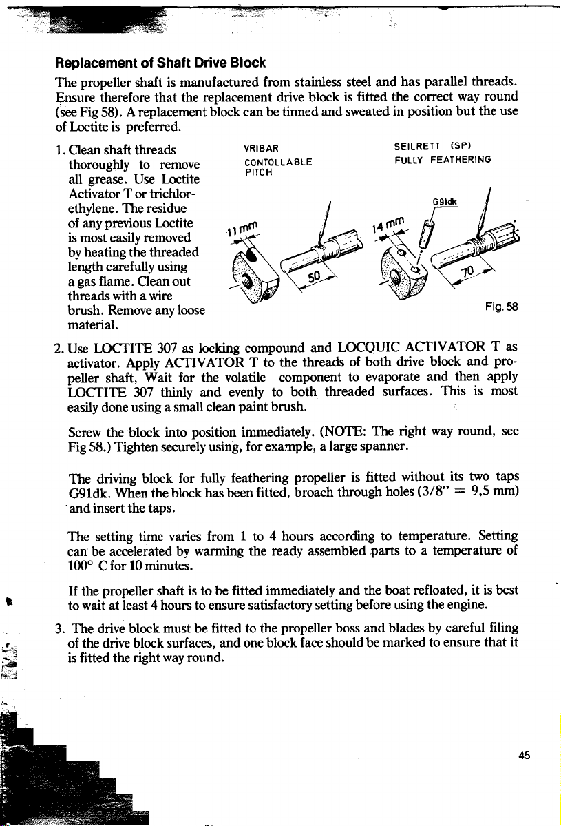
Replacement of Shaft Drive Block
The propeller shaft is manufactured trom stainless steel and bas parallel threads.
I;:nsure therefore that the replacement drive block is fitted the correct way round
(see Fig 58). Areplacement block can be tinned and sweated in position but the use
of Loctite is preferred.
1. Oean shaft threads VRIBAR SEILRETT (SP)
thoroughly to remove CONTOLLABLE FULLY FEATHERING
all grease. Use Loctlte
Activator T or trichlor-
.of any pre~ous Loctite rn \4 rnrn ,/ :.- .
lsmost.easllyremoved
length carefully using ,c . ' 10
a gas flame. Oean out 50
threads with a wire
brush. Remove any loose Fig. 58
material.
2. Use LOCfITE 307 as locking compound and LOCQUIC ACfIVATOR T as
activator. Apply ACfIVATOR T to the threads of both drive block and propeller shaft, Wait tor the volatile component to evaporate and then apply
LOCfITE 307 thinly and evenly to both threaded surfaces. This is most
easily done using a small clean paint brush.
Screw the block into position immediately. (NOTE: The right way round, see
Fig 58.) Tighten securely using, tor example, a large spanner.
. PITCH
~j. ~-: ~ tI
iethylene. The residue G91dk
~""'. by heatlng the threaded ,~ Á~ ! .:~. 1
The driving block tor fully feathering propeller is fitted without its two taps
G91dk. When the block bas been fitted, broach through holes (3/8" = 9,5 mm)
. and insect the taps.
The setting time varies trom 1 to 4 hours according to temperature. Setting
can be accelerated by warming the readyassembied parts to a temperature of
100° C tor 10 minutes.
If the propeller shaft is to be fitted immediately and the boat refloated, it is best
.. to wait at least 4 hours to ensure satisfactory setting before using the engine.
3. The drive block must be fitted to the propeller boss and blades by careful filing
r!"'i of the drive block surfaces, and one block face should be marked to ensure that it
~ is fitted the right way round.
~f!~
45

0 ~WfJ-""" viJSt..I!.o:.d l
--~ I
z.el? tlfrklle...~ ~Î.s~ 1c1..JIo,)',e-!("
43. REVERSE GEARBOX ~o..
The reverse gearbox works on the principle of self-adjusting CODe clutches for ahead
and astern drive. When the gear lever is moved, the gear shaft (4), together with
flange coupling (7) and propeller shaft, is moved forward for ahead drive and back-
ward for reverse.
The clutch is held engaged by the propeller thrust. To avoid a degree of clutch slip
during engagement, the clutch lever should be engaged with a light pressure. As
soon as the propeller bas begun to generate thrust, the clutch will hold in. The lever
must not touch engine casing etc.
1 The nature of this method of clutch operation makes it important that exact align-
ment between engine and propeller shaft is maintained. Any misalignment fuld
g;ive rise to clutch slip. -';..,die~ c\t. "-"o\.." e.. ~~ sc.~voe~J "ie~ tJ"~"" ~~
\0\ e'e"" ,C)"" 5"\ "',~", t.l-t. \It~y!eli"'5 Q~j"'I/&o"~).~ QIl.~ ~dd s)'~e..
If the water level in the boat is such that water may reach the oil seals in the rear
face of the gearbox, operation of the gearbox should be avoided until the boat bas
j been pumped out. This will prevent damage to the hall race on the far side of the
seals.
Replacement of Oil Seals (Gearbox Engines)
(as required):
1 --7:-'[ 1. Re~ove. dip~tick (2) and pump out the
", Fig. 59 lubncatlng 011.
,I. 2 3 .
)1 2. Remove the flange couplmg bolts and ease
"""-' I, I 4 5 6 7 8 9 the propeller shaft and after coupling
,~ I
- ~~-j I I I
~ 1 [, "
1 1 flange approx9cm tothe rear.
=1i 7?'b / ~ ) 'i,flij;:;~: ~~:~~~~y ~~h~:~t ~~~~~h~:e~~~~~:nt-
~~I--J~ rDfî;î!j
~ 10 !;' -
4. Set gear lever in the fully back position. Position two wooden blocks, about 1"
truck, between coupling flange (7) and gearbox flange (3). Press the coupling
flange off by pushing the gear lever carefully forward. If this is not effective, an
extractor must be used. Take care of the key (10).
!.', S. Tip the oil seals (S and 6) out of the gearbox flange (3) and clean the sealing face.
.;;
6. Insert newoil seals, both with their open ends inwards. The outer seal bas the dust
lip turned outwards. Place a flat piece of wood over the oil seals and knock them
in, ODe at a time. Apply a little grease. See that the grease nipple hole is open into
the space between the oil seals.
7. Position the key and ease the coupling flange (7) carefully onto the gear shaft (4).
Fit the lock washer, knock the nut tight and lock with locking tabs. Fill with
fresh oil. Fit propeller shaft.
46
~~ ~ ,J 3. S.traighten the locking tabs and knock the
~ ~~~-[,-- nng nut (9) loose. Remove lock washer (8).
~tk _.:i!i~-

Gear Lever Movement
If the ahead clutch CODe lining becomes wam Ca 100
af ter a long time in use, the lever must be
pushed further forward to engage the clutch. 1
This cao be adjustèd using shims between the
clutch CODe forward face and the ballrace on the
shaft spigot in the gear housing (2).
Similarly, if the astem clutch CODe line becomes
wam, the clutch lever backward movement cao
be reduced by removing the shims from the 3
forward end of the ballrace in the operating
sleeve (3). This is a major repair and should be
carried out by a SABB Workshop or other
approved agency. Oetailed instructions will be ~
supplied on request. ~
Check: Fig. 60
1. The correct gear lever travel hom neutral (A)
to ahead (B) or astem is approx 100 mmo
44. CHECKING INJECTION PUMP (as required)
The injection pump is rugged and reliable provided that the fuel Dil is clean and free
of water, but it is a precision product and will not stand improper use.
The pump cao be removed foT checking but removal of the delivery valves (2) should
only be carried out by qualified service representatives, as should any repairs to the
pump.
The pump cao be taken out without removing the govemor cover.
1. Govemor control lever (Fig 2 ,
4, item 2) set to "stop"
(upwards).
a 2. Disconnect Dil base (3) and 5 3
c, fuel pipes and bend to ODe
~, .
. 3. Remove securing outs (4), .
~r' slde.
using tubular or other \
suitable spanner, and lift out
';::: through 90° and withdraw . -:::;-
anti-clockwise (forwards)
~L- . - .
- ,
\.. pump halfway. Turn pump
;11 foT inspection. /
~J1f!1'f' Fig. 61 6 - I 47
,
"'
.' .;""..~
,'" .\I~ ,,;;:;~

Assembly:
4. Insert screwdriver (5) in the gap in the pump shim{ 6) and pump housing so that
the governor arm (Fig S4 item 5) can be carefuUy levered out and held in that
position.
5. Hold the pump as shown. Ease it downwards into the opening until the lowest
part of the pump bas passed the governor arm and hold in that position. Withdraw the screwdriver, turn the pump clockwise through ~o and press it down
into position.
6. Ensure that the fuel pump spigot engages with the slot in the governor arm. This
can be feIt as a slight "click" or dead movement when the governor controllever
is moved in the "stop" position.
G. WINTER LAVING UP
Before laying the boat up lor the winter, protect the engine as foUows:
Change the oil in crankcase and clutch or reverse gearbox.
Grease aU nippies.
Oose gate valve and allow engine to idle lor half a minute to expel any water trom
the exhaust hose.
Drain the water trom engine, silencer, water pump and piping.
For sea water cooled engines, flush cooling system through with fresh water.
For fresh water cooled engines with closed cooling system, there is no need to drain
provided that anti-freeze bas been added. See "Fresh Water Cooling". If the system
is drained, any external cooler must be blown dry.
If a heat exchanger is fitted, the gate valve must be closed and sea water drained
trom the heat exchanger. Open impeller pump cover, extract impeUer and replace
cover.
Unscrew start cigarette plugs and spray 10 shots (about 10 cc) of lubricating oil into
each cylinder. Turn the engine over a lew times. Repeat once or twice during the
';, r: cource of the winter.
'ic
!:"'~ Oean engine externally and touch up with engine paint.
, Keep engine covered.
Drain off any condensed water in the fuel tank and top up with fuel.
Remove battery trom boat, charge and store in a dry trost-tree place. The battery
should be recharged at intervals two or three times during the winter.
Disconnect the flange coupling and separate slightly. This ensures that the
shaft will not be damaged if the huIl should distort during the lay-up.
48
a ..';;.; .;tJ !f
:,; ."

PREPARATION AFTER WINTER LAY-UP:
When preparlng the engine following winter lay-up, it pays to spend as much time
on the work as necessary .
When the boat bas been re-floated, the engine E
alignment should be checked.
If the engine is supported in rubber mounts, the ~;
adjusting nuts (0) above and below the support
frames should be checked. Also check the bolts(E).
Sea Water Cooled Engines:
Inspect the zinc anode plug (also tor fresh water Fig. 62
cooled engines) at the forward end of the silencer.
Renew if necessary .
Oose drain cocks. Make sure that the gate valve is open and that the exhaust hose
is connected to the silencer.
Fit a fully charged bartery and connect it as shown in the wiring diagram.
NOTE: Never start the engine before the alternator and regulator have been
connected to the bartery. Adjust V -belt tension.
Check that there is fuel in the tank. Drain off sediment.
Check that there is oil in engine and clutch or gearbox. Grease all nippies and
propeller boss.
Fresh Water Cooled Engines (without anti-freeze):
Inspect zinc anode plug at the forward end of the silencer. Suction and return
hoses must be connected to the engine and to the extemal cooler. Fill system
with clean fresh water.
'~
J) CHECKING THE ALlGNMENT
- The alignment. of engine and propeller sha.ft b" ",i:!
~ should be checked. a.iter the boat bas ?een m \ C!;'c
~ the water a sufficlent length of time to '
I permit the bull to set. The alignment is
.è controlled with a feeier gauge between the
coupling flanges (see fig 63), in 4 positions
up, down and laterally. (.
If required loosen engine fixing bolts and fit
';0: shims under frames until flanges are exactly ~',
~ parallel. Check again after engine is fixed. Fig.63 --@.
K-
--
49

IRREGULAR ENGINE OPERATION
Fault Location
;fJIIIRI""'"~l. ENGINEFAILSTOSTART
a. Governor control not full open.
b. Crankcing speed too low.
c. Dry cylinder walIs. Lubricate with 4-5 shots of lubricating oil into each cylinder
C d. Water in fuel.
using squirter cao through plug holes.
e. Fault injection. Check nozzIes.
(';'(3Nt--ltl
2\LACM>F COMPRESSION
a. Check correct valve clearances (0.3 mm, page 40).
b. Valve sticking. Check valve movement by hand. If necessary squirt! fuel oil
through springs to lubricate valve sterns while pressing down by hand.
c. Start cartridlZe residue on valve seating. Listen for leakage while turning engine
over by h--;;nd: '» iOAfr.;'F
/ A/P"'~;"'.F4'-e.çAl
3. ENGINE HARD TOLCRANK
a. Lubricating oil too thick.
b. Bent propeller shaft. Check alignment at flange coupling (page 49).
"'.s""-1f
4. LACK OF POWER
a. Blocked fuel filter. Renew filter element (page 24).
b. Air in fuel system. '-
c. Dirt in injector nozzIes (page 26).
d. Blocked air filter. I _A'/'__~
e. Outch slipping (page 39). ~()f'~ .
f. Incorrect valve clearances (page 40).
g. Blocked exhaust pipe. Collapsed rubber exhaust hose (kinking or over-
heating).
f$~""T I
5. ENGINE STOPS
a. Fuel starvation. Fuel cock closed.
b. Air or water in fuel system.
c. Injector pipe leak.
d. Too little lubricating oil. Top up. Check compression after allowing to cool until
easy to turn over. Re-start and increase load slowly.
6. SMOKY EXHAUST
a. Blocked nozzIes (page 26).
b. Worn pistonrings and poor compression.
c. Valve leakage. Oean and re-grind.
d. Air intake blocked.
50

Ç,;;:;i~~!~~v"f ' ,lA
7. UNEVENR- I ING, HUNTING
a. Govemor parts ~ng due to thick, dirty oil. Remove govemor cover and wash
out with fuel oil (page 41).
Change lubricating oil (page 17). ,
8. ENGINE WILL NOT IDLE ~tá1itJnp,~ cf'lC(a(e.,1
a. Valve leakage
b. Nomeblocked(page 26).
c. Incorrect relative setting of governor con trol lever and remote controllever.
d. Govemor idling spring too slack (page 38).
e. Blocked filter element in fuel filter (page 25).
9. EXCESSIVE LUBRICA TING OIL CONSUMPTION
a. Oilleakage past defective seals. ' .b. Cylinder liners and piston rings worm. Check- wear !l;fid change rings if
necessary.
10. WW OIL PRESSURE
a. Lubricating oil too thin.
b. Too little oil. Pump sucking air.
c. Defective oil pressure gauge.
e. Dirt in oil pressure relief valve (pages 15 and 19).
f. Lubricating oil pipe leakage.
g. Engine room too hot, inadequate ventilation.
11. ENGINE KNOCKING
a. Blocked nomes. Leak-oHpipe blocked.
b. Mechanical failure. Check valves, big-end bearings and gudgeon pins.
12. ENGINE OVER-REA TING OR WATER PUMP NOT FUNCTIONING
a. Water inlet or water valves blocked.
b. Defective water pump diaphragm. Leakage from drain holes in pump flange.
c. Engine room too hot, inadequate ventilation.
13. KNOCKING SOUND FROM CLUTCH OR PROPELLER
'c a. Lack of grease in propeller boss.
8] b. If stempo~t is to truck, this c.an give rise to knocking at the clutch when at futl
~ power. FaIr oH stempost to glve smooth water flow to propeller.
, c. Shaft coupling loose.
'"
.: 14. PITCHCONTROLHARDTOOPERATE
,;~ a. Inadequate greasingöfpropeller or incorrect grease.
~:i Grease propeller and sliding balts (pages 20 and 21).
" b. Bent propeller shaft. Check alignment (page 49).
,.
~
c. Damaged propeller. -
d. Propeller shaft wom in stuffing box.
e. Wom thrust rings in propeller boss. Renew rings or add shims (page 43).
51

1S. CLUTCH SLIPPING ~
r a. Qutch not properly engaged.Press lever right forward and check thai it does DOt:'))]
, foul engine casing etc.
b. Incorrect clutch tension (page 39).
16. REVERSE GEARBOX SLIPING
a. Gear lever movement obstructed.
b. Bent propeller shaft. Check alignment (page 49).
c. Too much oil in reverse gearbox.
d. Shaft coupling loose. Check set screws.
e. Stern hearing gland loose.
f. Excessive lever movementdue to defective hearings in operating sleeve.
g. Excessive lever movement due to CODe lining wear.
Adjust with shims on clutch CODe forward face (page 47).
17. ENGINE NOT RUNNING EVENL Y ON BOTH CYLINDERS
a. Faulty nozzle. Change over or replace (page 26).
b. Valve leakage on ODe cylinder (page 40).
RECOMMENDED ON BOARD SPARES
For long journeys or holidays, we recommend thai a standard maintenance spare
parts kit should be held on board. .
Th ki . I . f h j;JRA:-t:k lil/! .
ese ts contron a se ectlon 0 t ose gas ets, plpes an spare parts t at expenence
d h .
bas shown to be most useful.
{i"
For type 2H : Maintenance Spare Parts Kit V -12.
For type 2HG: Maintenance Spare Parts Kit V -12A.
also available:
Maintenance Set of Gaskets P-10A(included in V-12).
Repair Set of Gaskets P-11A.
0- Rings and Oil Seals 0-12.
52

SABB DIESEL - SALES AND SERVICE
DEN MARK: UNITED KINGOOM: CALEFORNIA/OREGON:
NORDSABB KAJ KL YN A.S SABB DIESELS U.K. DREADNOUGHT
Runetoften 8 Emsworth Marine BOATWORKS
8210 AARHUS V - Denmark Engineering Ltd. Box 221
Telephone 06-24 36 00 Emsworth, CARPINTERIA,
FINLAND: Telephone 71152 Telephone (805) 684-3492
KY H. BLOMSTEDT KB
Arildsvägen 15 IRELAND. WASHINGTON ALASKA.
HELSINKI 37 - Finland' , .
Telephone 90-55 85 01 A. H. MASSER LTD. MARINE DIESEL
FAROE ISLAND. DUBLIN 10 -Ireland 2834 N.W. Market Stro
VIGGOKJELD . Telphone(01)364511 SEATTLE,Wa.98107
Thorshavn Telephone (206) 784-4888
Telephone 11707 MEDWAY MARINE LTD.,
ICELAND: 11, Enrico Mizzi Stro NOVIA SCOTIA:
ARNIVALMUNDSSON MSIDA ROSE BAY BOATSHOP
Ranag0tu 29, Akureyri R.R.1
Telephone (96) 2-38-15 CYPRUS: ROSE BAY, N.S. BOJ 2XO
SWEDEN: Box 1989 SEYCHELLES IS.:
ING.FA GöSTA WARLIN AB NICOSIA - Cyprus M.A. Rouillon
Carlandersplatsen 4 Telephone 66121 Chevron Pty.
41255 GOTHENBURG - VICTORIA, Mahé
Sweden NEWFOUNDLAND-
. Telephone169478 CANADA: ECUADOR:
BE-NE-LUX: SERVICE LTD. & CIA. LTD.
BV Ing.bureau Box 250 Box 2680
A. J. VERSCHUUR ING. CARBONEAR - QUITO
Scheepmakerstraat Newfoundland
KATWIJK AAN ZEE - Telephone (709Y-722-0036 AUSTRALlA
Holland (S.W., W.A., N.T.):
Tel. 01718-16344/16346 NEWZEALAND: WESTFARMERS
FRANCE (Bretagne) 289-299 Broadway Box 21
ETS POUGET Newmarket BASSENDEAN, W.A. 6054
"Guipavas AUKLAND,'N.Z. Telephone794511
c' B.P.24 Telephone500-129
29266BRESTCEDEX TASMANlA:
,,- CHANNEL CHARTERS
~ GERMANY: Box 34
I~- GERD AUGUSTIN Sandy Bay, Hobart 7005
23 KIEL 16
Immelmannstrasse 22
Germany
Telephone 0431/36 2191
Hants PO108BW Calif. 93013, U.S.A.
Kylemore Road ENGINE HEADOUARTERS
MALT A: (206) 789-2300
STAR FIBER GLASS LTD.
THE EARLE FREIGHTING ARTHUR FRIED
FISHER & BLUNDELL LTD. TUTT BRYANT
-
53
"

/ .
Reserwedelskatalo'g t :
~ Spare parts catalol;'ue
Type .211 - Marine Diesel
I TYPE 2H: Med reduksjon 2:1, frikobling -
omstyring og 2-bladet vribar propeli. " ,.;:;:
With reduction 2:1, clutch, 2-blade ,~"
controllable pitch propeller.
TYPE 2HG: Med reduksjon 2:1, reversgear og
3-bladet tast propeli, venstre.
With reduction 2:1, reverse gear and
3-blade solid propeller, lelt (LH)-
TYPE 2HEG: Med reduction 2:1, reversgear og
3-bladet tast propeli, heyre.
With reduction 2:1, reverse gear and
~ 3-blade solid propeller, right (RH).
..c.
.~~.
J
. TYPE 2HSP: Seilrett propeli. - Spesialutferelse
tor seilbater, med frikobling og
omstyring tor 2-bladet seilrett propeli.
'+:
Engine with fully feathering propeller.
: ~
. - tI
SABB AfOJOR /JJ.@ ~~
TIf. (05) *260504. Telegramadr.: Sabbmotor. Telex: 42559 Sa bb n
BOKS 2728 . 5010 BERGEN - NORWAY
.,
'ê
"
\
Jê

Bruk av reserve deis kata logen
Katalogen er arrangert gruppevis, slik at hver tegning felges av tilherende stykklister. Delene er merket fra 1 og oppover fOT hver tegning.
Stykklistene angir posisjonsnummer, norsk/engelsk tekst, delens navo,
eventuelle spesifikasjoner og delens nummer. Enkelte posisjoner innen
hver stykkliste er tilfeyet«S» eller «SI-» rOTan delens nummer. En slik
SI-gruppe angir minste naturlige monteringsgruppe (samiegruppe) pa
motoren.
Eks.: Topp/okk med forkammerinnsats og ventiler Sl-2Hl lA B.
Det er fordelaktig a benytte samlegruppene i sterst mulig utstrekning.
NYTT DELENUMMERSYSTEM 1979
I denne trykking er det nye delenummersystemet gjennomfert. Delens
nummer etter gammelt system star oppfert i parentes.
1975 var et overgang sar fra tommegjenger til millimetergjenger fOT
nye motordeier og utstyr. Tidligere skruer/mutre etc. med tommegjenger angitt, star ogsa oppfert i parentes.
RESERVEDELER
De alltid oppgi motorens type,
byggeàr og fabrikasjonsnummer.
Eksempel: 2H. 79. 100
MOTORSKILT/SERVICE IDENTIFICATION PLATE 2HG. 79. 25
Motorskiltet er plassert pa styrbord side av topphetten.
Videre oppgis del navo og del
nummer.
Bergen, mars 1980.
J.'f~':/ :., J l.t.i.1'

How to usa the Spare Parts Catalogue
~
. the following parts lists. The parts on each illustration are positioned
The catalogue is arranged such that each illustration corresponds to
from 1 upwards.
The parts list gives position, Norwegian/English part name, specification if any, and part number. In some positions the part no. have an
«S» or «SI-». Such parts are Assembly Groups, i.e. groups of parts
which form natural assemblies to be fitted on the engine.
EXAMPLE: Cylinder head w/Swirl Chamber and Valves Sl-2HIIAB.
It is of advantage to order spares to the Assembly Groups.
NEW PART NOS. AFTER 1979
In this catalogue the new part no. system is completed. Previous part
nos. are printed in brackets.
Metric threads replace Imperial Threads (inch) fOT new engine parts
and components, starting from 1975. In this catalogue the previous
Imperial Threads are also listea-in b~ackets.
WH EN ORDERING SPARES, ALWAYS SPECIFY:
1. Engine Serial No. (Engine model-year of manufacture-number).
Example: 2H. 79. 100
2HG. 79. 25
2. Part name, part no. and quantity wanted.
The number plate is fitted at starboard side of cylinder head cover
(see fig. on page 2).
Bergen, Norway, Mars 1980
J."1~':I:.IJL~ .u

SABB DIESEL-SALES AND SERVICE
DEN MARK: UNITED KINGDOM: SEYCHELLES IS.:
NORDSABB.KAJ KL YN A.S SABB DIESELS U.K. M. A. ROUIILON
Runetoften 8 Emsworth Marine Chevron Pty.
8210 AARHUS V-Denmark Engineering Ltd.-Emsworth VICTORIA-Mahé
Telephone 06-243600 Hants PO10 8BW
Telex 64123 Telephone 71152 EQUADOR:
FINLAND: IRELAND: Box 2680
ARTHUR FRIED & CIA. LTD.
FINN-SABB A. H. MASSER LTD. QUITO
025 20 Lappb01e Kylemore Road
Telephone 266394 DUBLIN 10-lreland WESTERN AUSTRALlA AND
FAROE ISLAND: PILOT MARINE
VIGGO KJELD MALTA: 178 St. George's Terrace
Telephone (01) 364511 NORTHERN TERRITORIES:
TORSHAVN MEDWAY MARINE LTD. Perth
Telephone 11 707 11, Enrico Mizzi Stro Western Australia
MSIDA Telephone 321 5851
ICELAND: VICTORIA AND
Telephone 51 2555
ARNI VALMUNDSSON NOVA SCOTIA: SOUTH AUSTRALlA:
Ranag0tu 20, Akureyri ROSE BAY BOAT SHOP F. S. BENTLEY &
Telephone (96) 2-36-15 R.R. 1 ASSOCIATES PLY. LTD.
ROSE BAY, N.S. BOJ 2XO 56 Kambarà Drive
SWEDEN: Mulgrave
ELLÖS MARIN THE EARLE FREIGHTING Victoria 3170
.: Box 6326 SERVICE LTD. Telephone 547 25 70
ti: S-44080 Ellös Box 250
~
;.:;& Telephones: CARBONEAR-Newfoundland
.,: 0304-50835 - 031-122841 Telephone (709) -722-0036 TASMANlA:
~ CHANNEL CHARTERS
"': BE-NE-LUX: U.S.A.: Box 34
,;- BV Ing.bureau SABB EAST-CLARK WEBSTER Sandy Bay, Hobart 7904
,~ A J VERSCHUR ING R.F.D. 2
'...~;, . . . Box 307 NEW ZEALAND:
y'ëê'lScheepmakerstraat
c1t";\iTel. 0 1718-163-44/16346 289-299 Brodway Newmarket
,;:î;,~ CALIFORNIA/OREGON: AUKLAND, N.Z.
~; DREADNOUGHT BOATWORKS Telephone 500-129
~ FRANCE (West): Box 221
MARBERIC'H CARPINTERIA MID-AMERICA AND
Z. I. Du Vernis California 93013-U.S.A. THE GREATS LAKES:
Ste Anne du Portzic Telephone (805) 684-3492 SAL TY BOATS
F-29200 Brest Box 185
: Tel. 45.06.24-45.03.87 WASHINGTON, ALASKA: NEW BAL TIMORE
.. MARINE DIESEL ENGINE 48047 Michigan, U.S.A.
GERMANY: HEADQUARTERS Telephone 313-725-5571
GERD AUGUSTIN 2834 N.W. Market Stro
23 KIEL 16 SEATTLE, Wa. 98107
Immelmannstrasse 22 Telephone (206) 784-4888,
Telephone 0431/3621 91 (206) 789-2300
PI .
t N H 03865)~7:~ATWIJK AAN ZEE-Holland ais ow .. FISHER & BLUNDELL LTD.
~

INNHOLDSFORTEGNELSE/CONTENTS: ILL.: Page:
Topp - Lyddemper/
Cylinder Head - Silencer A 7
Sylinder - Stempel/
Cylinder-Piston B 13
Veivhus - Veivaksel - Svinghjul/
f Crankcase - Crankshaft - Flywheel C 17
Pumpekasse - Handstart/
Gear Housing - Hand Start D 23
Regulatorluke/
Governor Cover E 31
Kjelevannspumpe - Vannventil/
Cooling Water Pump - Valve Housing F 35
Ekstra vannpumpe - Impellerepumpe/
Extra Water Pump - Impeller Pump G 39
Ferskvannskjeling/
FreshWaterCooling H 43
Brennoljesystem/
Fuel System .. . . . . . . . . . . . . . . . . . . . . . . . . . . . . . . . . . . . I;. 47
Elektrisk utstyr/
Electrical Equipment J 51
R egula torf or lengelse/
Remote Governor Control K-L 55
Tilkoblingssett/
Remote Control Adaptor Kit L 57
Kobling og omstyring/ ~
Clutch and Propeller Control . . . M 61 j
Reversgear :-- Type H-1971/ i
Reverse Gearbox (2HG) N 69 ~
Reversgear. - Type E-1978/ )~
Reverse Gear (2HEG) 74
.. Vribar propell- Seilrett propell/
ControllabIe Pitch Propeller - Fully Feathering Propeller 0 77
Fast propelI - venstre og heyre/
Solid Propeller - Left and Right Hand P 81
Fast propelI - Vannsmurt stevnflens/
Solid Propeller - Water Lub. Stern Bearing Q 85
Side/
Pakningssett/
Sets of Gaskets. . . . . . . . . . . . . . . . . . . . . . . . . . . . . . . . . .

.
I.!.. ~~
'" ~ 0\
18~
'"
",-
~
r(;.. - ~
.4.. Ol
y--- ~
"11
'0
'"
0)
"11
0)
7
"'--~ .
0\
00
\.~
'r;)
10
10
, . ~ a COOl
"' a .
: 'CC
'..~,~.:;'.;~~. ~~'~:
- 'rl
i "w
a . "J.I' /
- '/J~ . - .
.', >':..0101/
I
k;"
"'!
"'
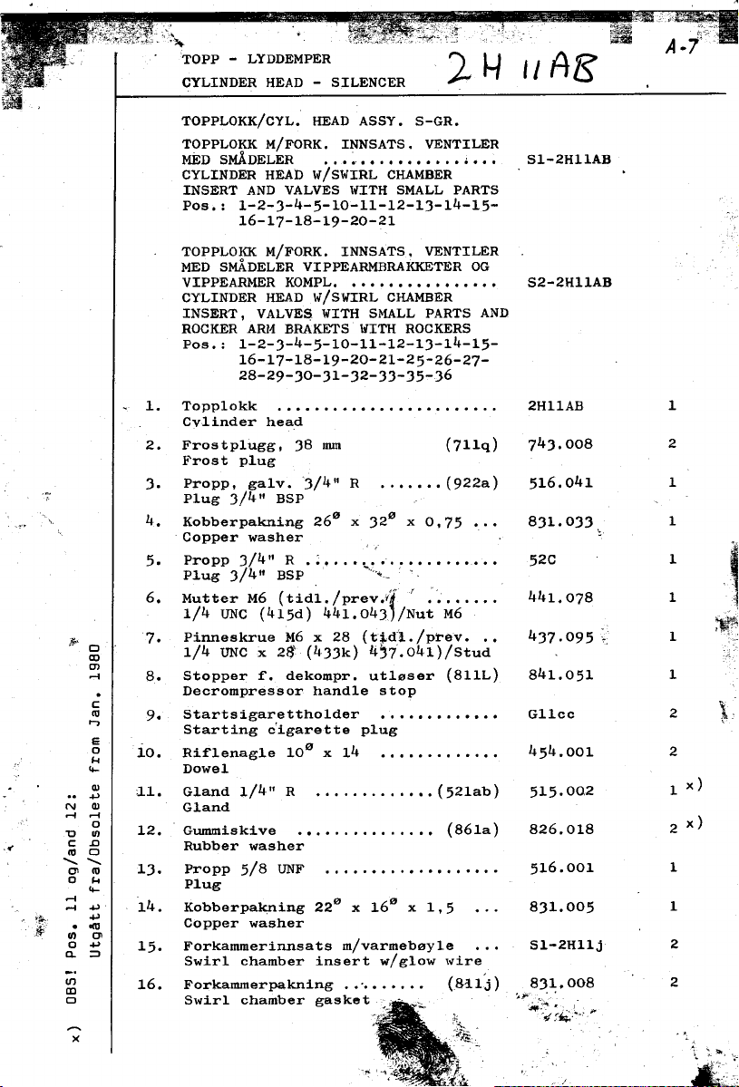
'" ,,""
c':~~ e A .1":;~'
TOPP - LYDDEMPER !") H A 9?
CYLINDER HEAD - SILENCER h ,/ (.)
i: ,
TOPPLOKK/CYL. HEAD ASSY. S-GR.
TOPPLOKK M/FORK. INNSATS. VENTILER
MED SMADELER ...~ Sl-2H11AB
CYLINDER HEAD W/SWIRL CHAMBER
INSERT AND VALVES WITH SMALL PARTS
Pos..: 1-2-3-4-5-10-11-12-13-14-15-
16-17-18-19-20-21
TOPPLO!(K M/FORK. INNSATS. VENTILER
MED SMADELER VIPPEARMBRAKKETER OG
VIPPEARMER KOMPL. S2-2H11AB
CYLINDER HEAD ',,/SWIRL CHAMBER
INSERT, VALVE$ WITH SMALL PARTS AND
ROCKER Affi4 BRAKETS WITH ROCKERS
Pos.: 1-2-3-4-5-10-11-12-13-14-15-
16-17-18-19-20-21-25-26-27-
28-29-30-31-32-33-35-.]6
'.1. Topp1okk 2H11AB 1
Cv1inder head
2. Frostp1ugg, 38 mm (711q) 743.008 2
Frost plug
3. Propp, ga1v. 3/4" R ., (922a) 516.041 1
, Plug 3/4" BSP
.,', lt. Kobberpakning 260 x 320 x 0,75 ... 831.033 1
Copper washer :. "
5. ProPP3/4"R.; 52C 1 ,"
Plug 3/4" BSP ""..~ ' ,
6. Mutter M6 (tid1./prev.rt r '... 441.078 1 1
1/4 UNC (415d) 441.043J/Nut M6 ~
,~ 7. Pinneskrue M6 x 28 (tj,d'l./prev. .. 437.095 1 .eÓ}
~ 1/4 UNC x 2$' (433k) 4'7.041)/Stud ;'"
~ 8. Stopper f. dekompr. ut10ser (811L) 841.051 1
. Decrompressor handle stop
~ 9. Startsigarettho1der G11cc 2 ':1;
..,. c
E 0
~ 10. Rif1enag1e 10 x 14 ..'.. 454.001 2
"- Dowe1
..2 ll. G1and l/lt" R (521ab) 515.002 1 x)
N Q) G1and
~ ~ 12. Gummiskive (861a) 826.018 2 x)
.. ~ @ Rubber washer
"è."'m l3. Propp 5/8 UNF 516.001 1
0 ~ Plug
'. ~ . ~ Copper washer
~ 14. Kobberpa~ing 22 x 16 x 1,5 ... 831.005 1
, In 0\
0 ~ 15. Forkammerinnsats m/varmeb0y1e '.' Sl-2H11j 2
~ ~ Swir1 chamber insert w/g1ow 'vire
Starting cîgarette plug
0 0
~ 16. Forkammer~kning (M1J) .831;.008 2
CJ Swir1 chamber gasket "",
-; . ',",
"
~;:~~'."",
-.. 1. :;: 'i"
.
&{ ' c ,
'~cê

LYDDEMPER
CYLINDER HEAD - SILENCER
17. Venti1styring 2HJ4mb 4
Va1ve guide
18. Ventil, innsugn. og eksos 2HJ4KB 4
Va1ve. in1et and exhaust
19. Venti1fjmr (7J4c) 711.001 4
Va1ve spring
20. Venti1fjmrskive . ... '" ... 2HJ4nb 4
Va1ve spring collar
21. Venti1fjmrkon 2HJ4pb 4
Va1ve spring split cone
22. Lyddemperfesteskrue MlO x 1J5 .,. 4J7.080 2
(tid1./prev. J/8 UNC x 1J4 (411g) .
4J7.066)/Stud
2J. Under1agsskive ... ... "" (72Jh) 725.010 2
Washer
24. Mutter MlO 441.052 2 ..-~,-
(tid1./prev. J/8 UNC (415g)
441.011)/Nut MlO
VIPPEARMBRAKKET MED VIPPEARMER .,. Sl-2HJ4R
- Pos.: 25-26-27-28-29-JO-Jl-J2
J,: ,
,~~ 25. Vippearmbrakket 2~J4R 2
, Rocker arm bracket
~
ROCKER ARM BRACKET WIT" ROCKERS
iP- 26. Vippearmbo1t 2HJ4j 2
~ Rocker arm shaft
it 27. Vippearm 2HJ4Qb 4
~ Rocker arm
,., Vippearm med foring .. . . . . . . . . . . ~ Sl-2HJ4Qb 4
. Rocker arm 'vi tli bush
: ;',
..
.~ VIPPEARM MED FORING OG SKRUE (MlO) S2-2HJ4Qb
,.a RpCKER ARM WITH BUSHING AND ADJ. -
.,~ SCREW (MlO)
."~
,..'~
~ 28. Vippearmforing. 15 x 19 x 20 621.004 4
f~ Rocker arm bushing
29. Slcive,PS15x22xO,5 ...(7J4L) ,712.015 4
'" Washer
~Z JO. Seegerring, A15 (7J4j) 7J4.oJ9 4
.. Circ1ip
i "
J1. Vippearmsti11skrue, MlO xl GJ4.001 4
(tid1./prev. 5/16"- GJ4s. pos J1a)
Rocker arm adj. screw
:t
~

TDPP - LYDDEfYlPER
. CYLINDER HEAO - SILENCER
!
J2. Vippearmsti11skruemutter, MlO x 1 441.054 4
(tid1./prev. 5/16'1 (415e-441. 044)
ti1/to GJ4s pos. J1a)/Nut M10x1
"
JJ. Hodeskrue M12 x 55 4J2.00J 2
Bolt
-
~ S-6J4b-J) m/O-ringer/with O-rings Sl-612.040 1
J5. 0vre vippearm-smererer (tid1./prev. 612.040 (1)
Rocker arm lub pipe. upper
J6.. O-ring, SOR 1, J.1 x 1,6 ... (8J4g) 821.0J5 J
O-ring
40. Venti11efter ."'.".""."."". 2HJ4g 4
Va1ve lifter
c VALVE LIFTER COMPL.
. Pos.: 41-42-4J
.;.-,." "'..
- 41. Fotstykke GJ4hL (4)
~5J. Dekompresjons1ager , 2H11db 2 ~
< 54. V-ring V-10 (911k) 824.021 2 ~
VENTILL0FTER0R KOMPL. ... Sl-2GJ4h 4
Push rad foot
42. Venti11efterer ..'.""""."".' 2GJ4h (4)
Push rad
4J. Toppstykke GJ4hk: (4)
Push rad top
TOPPHETTE MED DEKOMPR. HENDEL Sl-2H11F
Pos.: 50-52-5J-54-55-56-57-58- "
~~ 59-62-6J -~
,
50. Topphette 2H11F 1
Cylinder head cover
51. Toppbettepakning 0,5 mm (811s) 81J.027 1
Cy1. he ad cover gasket -
52. Dekompresjonsstang ,. 2H11h 1,
Decompressor shaft ~
Decompressor hearing ,.
V-sea1
55. Dekompresjonshende1 , 2H11hk 1
Decompressor lever
56. Spennstift, 5e x 22 (711r) 456.017 2
Lock pin
DEKOMPRESJONSUTL0SER KOMPL. ... Sl-2H11e 1
DECOMPRESSOR COMPLETE
Pos.: 57-58-59
~ROCKER COVER WITH DECOMPRESSOR ",
57. Dekompresjonsut1eser 2H11e (1)
Decompressor ~

..
10
TOPP - LYDDEMPER
CYLINDER HEAD - SILENCER
58. Fjmrfestepinn 60 452.031 (1)
Spring retainer
59. Dekompresjonsut10serforing . 2H11.001 (1)
Decompressor bushing
60. Dekompresjonsfjmr (711m) 712.903 1
Decompressor spring
61. Hodeskrue M8 x 65 (tid1./prev. ... 432.111 2
5/16 UNC x 2.5"(447c) 432.064)
Bolt
62. Slangenippe1, 3/8" R (BSP). plast 519.001 1
Hose nipp1e. PVC
63. Mutter 1/2" R (USP) ...'" ..(562b) 541.014 2
.. LYDDEMPER MED FLENSER S2-2H21C
SILENCER WITH FLANGES
Pos.: 65-66-67-68-69-70-71-72-73-
LYDDEMPER M/FLENSER OG EKSOSBEND S3-2H21C
SILENCER W/FLANGES AND EXH. ELBOW
Pos.: 65-66-67-68-69-70-71-72-73-
74-75-76-77
74-75-76-77-80-81-82-83-84
65. Lyddemper 2H21C 1
Si1encer
66. Termostatnippel19 ... 511.060 1
6k :.
~ Thermostat nipp1e ~.:. 67. Eksosf1enspakning , (821v) 814.035 2
,.' Exhaust f1ange gasket
6S.. B1indf1ens/vannpakning . 814.007 1
~' Blank f1ange/water gasket
69. Blindflens G21M 2
Blank f1ange
70. Hodeskrue MlO x 20 (tid1./prev... 432.011 4
3/8 UNC x 3/4" (466b)432.082)
Bolt
71. Eksosf1ensskrue MlO x 26 (tid1./ 437.083 2
prev. 3/8 UNCx25 (411mb) 437.069)
72. Frostp1ugg 38 mm ... (711q) 743.008 2
Care plug
73. Slangenippe1 3/8" R (nsp).. (56ge) 518.020 2
Hose nipp1e
74. Eksosf1ens G21E 1
Exhaust f1ange
75. Mutter MlO 441.052 2
(tid1./prev 3/8 UNC(415g) 441.011)
Nut MlO
76. R0rp1ugg 3/4" 516.004 (med zink-
anode 516.005) 516.006 1
Plug with zinc anode
77. Kobberpakning 260 x 32° x 0.75 ... 831.033 1
Gapper washer
~ ~
L "
à,... c

..
TOPP - LYDDEMPER
CYLINDER HEAD - SILENCER
78. Eksosf1ens/vannpakning (821va) 814.036 1
Exhaust f1ange water gasket
EKSOSBEND MED VANNINNSPR0YTING Sl-2H21.001 *)
EXHAUST ELBOW FOR WET EXHAUST
Pos.: 80-81-82-83-84 S2-2H21.001 **)
80. Eksosbend/Exhaust e1bow ... 2H21.001 1
81. Slangenip. 3/8"R/Hose nipp1e (56ge) 518.020 1
82. Propp ga1v. 3/8"R/P1ug BSP . ..(921a) 516.040 1
83. Slangestuss 1/2" x 115/Hose 841.026 1
84. Slangek1emme. 17-25 mm rustfri 921.003 2
Circ1ip. stain1ess steel
85. Luftmanifo1dpakn../In1. manif. gasket 813.028 1
86. Luftmanifo1d/ln1et manifo1d 2H11.003 1
87. Inns.demp.pakn./In1et damper gasket 815.025 1
88. Overgangsforskruning 3/8"R x M14.. 513.021 1
Reducing nipp1e
89. T-s1angenippe1/T-piece. PVC 519.002 1
90. Av1uftingss1ange 1/2" x 265 ..., 841.085 1
(Manifo1d-topphette)/Breather base
91. Slangestuss 1/2" x 160 841.084 1
~ (Manifo1d-startstativ)/Hose
d '
~.~ 92.. Innsugningsdemper med r0r. plast ... 927.009 1
~ dInlet damper with pipe. PVC
bD~
~'C 93. Pinneskrue M6 x 102/Stud .,... , 437.110 1,
'C~ 94. Under1agsskive/Washer .. 721.076 1 f
~ 0
'ci g 95. Mutter M6/Lock nut 441.076 1
g H 96. Hodeskrue M8 x 50 (tid1./prev. 5/16 432.022 1
H:!. UNC x 2" (422n) 432.070)/Bo1t
~ ro
~ ~ 97. Hodeskrue M8 x 25 (tid1./prev. 5/16 432.023 1
~ or: UNC x 1" (421k) 432.028)/Bo1t '
U)
ro ~ 98. Slangek1emme, 55-70 mm, rustfri 921.043 2
~~ Hose clip, stain1ess
;;;; 99. Gummi eksosr9r 1 3/4"x63° ..(837e) 841.056 1
~ ;j ;j
U) U) Rubber exhaust Pipe
~~ 100. Eksos.ryppf1ene 450 (me. mutter
~ ~ 443.01' 1 3/4" r,Cj.(BSP) (Sl-G21jc) '75.060 1
< ~ ~ Exhaust skin rittinc
~ ~
~ ~ 1.02. Elektrisk temperaturf01er (VDO) 953.010 1
H HEletrical temperature fee1.er
0 0
~~
~~
* *
*
, ,
,
t

B
~:~~S:J2 21 ' I. 26
~~::::~~ \; .~
:=@
, --~,::::)) .
~
~ 7
~, ~~
~.
.
7
"
',~
,
~~,
r 1 ~'3
" ~
~r'fT'" ..
V "

SYLINDER - STEMPEL
CYLINDER - PISTON
z
~ STEMPEL MED RINGER DG KRYSSBOLT Sl-2H32AB
D PISTON WITH RINGS AND PIN
~ Pos.: 1-2-3-4-6-7
l.:I
~ STEMPEL MED RINGER, KRYSSBDLT DG
~ VEIVSTAKE KOMPLETT MED BDLTER S2-2H32AB
~ PISTON WITH RINGS,PIN AND CONNECTING
~ ROD COMPLETE WITH BOLTS !
~ Pos.: 1-2-3-4-6-7-10-11-12-13-14
c: ..
~
~ c: 1. Stempel 2H32AB 2
0) a.
a.
~ 6 STEMPELRINGSETT (3 stk) 2H32.004 X)
~ ~ PISTON RING SET (3 pc:s)
"C Pos.: 2-3-4
.. :J
~01
~ ~ 2. Toppstempelring, forkrommet 2H32.001 2
00 0) Top c:ompression ring, chromium pl.
OO"C
>-c:
!;;.:J 3. Kompresjonsstempelring 2H32.002 2
0) Compression ring
~ :-
0) 0
~ ~ 4. Spesia1fj~r-o1jeskrapering 2H32.003 2
:J 01 Special oil con trol ring
~ 01
g.~ 6. Kryssbo1t H32P 2
00 ~ Gudgeon pin -
01
c: 0)
.~ 6 7. Seegerring, 35-1 (732a) 734.034 4
~.c:
O)~
"c';' VEIVSTAKE MEO DEKSEL, FORING ÇlG
0) BOLTER """""""""'~.'r S2-2H32EG 2
E 6 CONNECTING ROD WITH BUSHING ANO BOLTS
~ Pos.: 10-11-12-14
0)00
a ~.!:;; 10. Veivstake 2H32EG 2
~ Connecting rad
00 ~m
~~ 11. Veiv1agerdeksel mm I Connecting rad cap
NI'-D
. .N
~~~ 12. Krysslagerforing, 390 x 35 (632e) 622.012 2
. I Small end bush
zO) N~~
~~~ 13. Veivlager, 2 halve skAler, std. 70 mm 2H32F 2
. ~ 0) 0) Big end bearing, 2she11s
,,-DOO
~ 00 01 Veivlager, minusmAl 69,75 mm 2H32Fb (2)
0) 0) c: Big end bearing, undersize
~ c: B'~~ Veivlager, minusmAl 69,50 mm 2H32Fc (2)
Piston
Circlip
"
~ ~ 6 Big end bearing, undersize
~
~ ~.~ 14. Veiv1agerbolt M12 x ~5 432.003 4
"-"-a. Big end bearing bolt
~
x
~ .,
~ .
,~

14 SYLINOER - STEMPEL
CYLINOER - PISTON
20. Sylinderforing 2H21Nb 2
Cylinder liner
21. Foringflenspakning, 0,45 mm .. (823a) 831-015 2
Cylinder liner flange ring, std
Foringflenspakning, 0,56 mm (832ab) 831.016 (2)
Cylinder liner flange ring
Foringflenspakning, 0,36 mm (823ac) 831.017 (2)
Cylinder liner flange ring
22. Foringgummiring,
a-ring, SOR-68, 94,5 x Je (821p) 821.028 4
Cylinder liner rubber ring
SYLINOERBLOKK MEO VANNOYSER DG NIPPEL Sl-2H23AC
CYLINOER BLOCK WITH WATER NOZZLES
Pos.: 25-26-27-28
SYLINOERBLOKK MEO VANNOYSER, NIPPEL
OG SYLINOERFORINGER KOMPLETT S2-2H23AC
CYLINOER BLOCK WITH WATER NOZZLES,
NIPPLES ANO CYLINOER LINERS COMPLETE
Pos.: 20~21-22-25-26-27-28
25. Sylinderblokk 2H23AC ,1
Cylinderblock '
26. Styrehylse 631.001 2
Guide sleeve
~! 27. Kjelevannstuss 631.004 2
Nozzle
28. Nippel, vann inn, 1/2" R (511a) 511.050 1
Nipple, IlIater inletl/2" BSP
29. Toppakning 814,008 1
Cylinder head gasket
30. Sylinderblokk-veivhuspakning, 0,3 mm 813.013 1
Cylinder block-crankcase ga-sket
OBS!
For motorer fer 2H.79.270 (medio '79):
Sylinderblokk-veivhuspakning, 0,5 mm
(823g) 813.042
, For engine~ befare 2H-79-270 (med.'79):
NOTE'
Cylinder block-crankcase gasket, "
0,5 mm (823g) 813.042
~

~ i~1~
"' ., 0. I
ë
. "
r
!f.
~ ,. ",
t:
~... I
(
i ~-
.V ~
\,.' --0
\1 Cl)
\
\
i
\
\
\
~..
U
~~

VEIVHUS - VEIVAKSEL - SVINGHJUL
CRANKCASE - CRANKSHAFT - FLYWHEEL
VEIVHUS MED FUNDAMENTJERN ".'.' Sl-2H22AC
CRANKCASE WITH FRAME(S)
\ Pos.: 1-2-4a-l~b-(e11er/or l~c)-5-6-7
8-9-10-15-16-(17 separat)
VEIVHUS MED VEIVAKSEL OG LAGERFLENS S2-2H22AC
CRANKCASE 'fITH CRANKSHAFT AND MAIN
~ BEARING HOUSING
Pos.: 1-2-4a-4b-(e11er/or 4c)-5-6-7
VEIVHUS MED VEIVAKSEL, LAGERFLENS,
STREKKBOLTER, FILTER OG SVINGHJUL
KOMPLETT SJ-2H22AC
CRANKCASE 1fITH CRANKSHAFT, MAIN BEAR,
HOUSING, STAY BOLTS, LUB.OIL FILTER
AND FLYWHEEL COMPLETE
1. Veivhus 2H22AC (1)
2. Propp 1/4" m 6-kant hull 516.010 1
4a Fundamentjern, styrbord .'" """,., 2H22eh 1
4b Fundamentjern. babord , 2H22ev 1
4c Fundamentbrakket. grtmmioppheng .,. ... 2H25D (2)
5. Hodeskrue M12 x JO, Tensilock (422p) 4J2.072 12
8-9-10-15-16-(17)-18-(19 front)
20-21-22-2J-25-26-27-40-40a-40b
41-42-4J-44-45-46-47~48-55-57
58-59-60-61-62
Pos.: Alle unntatt/A11 except:
18-(19 bak/rear)-75-77-78-79
80-81-90-91-92-9J
Cranlccas e
Plug
Frame, starboard
Frame. port
~Iounting bracket. rubber mounting
Bolt
6. Nippel. oljetrykk. (56Ja) 511..040 1
1/4"R (BSP) - 1/2" UNF
Nipple. lub oi1 pressure
.. Copper was her
7. Kobberpakning 1.J~x180xl.5.. (844j) 8J1.019 1
8. Aktre kamakse1foring. JR50M 1622db) 622.002 1
Chamshaft bush. rear
9. Forr.- og midtlager-kamakselforing
(J825M) (622da) 622.019 2
Camshaft bush. front and central
10. Ramme1agerforing (622h) 621.016 1
Main hearing
~
~

.-- 18 VEIVHUS - VEIVAKSEL - SVINGHJUL
CRANKCASE - CRANKSHAFT - ELYWHEEL
15. Pinneskrue MlO x 35 (tid1./prev
3/8 UNC x 35 (434d) . (437.044) 437.102 14
Stud
16. Pinneskrue MlO x 27 (tid1./prev.
3/8 UNC x 25 (434a) (437.042) 437.100 2
Stud
17. Pinneskrue M10.x 135 (tid1./prev.
3/8 UNC x 135 (4)4b) "'" (437.043) 437.101 1
Stud
18. Mutter MlO (tid1./prev.
3/8 UNC (415g) """ (441.011) lj41.052 17
Nut
19. B01geskive , (723h) 725.010 17
Was her
20. Strekkbo1t M12 x 257 (tid1./prev.
M12 x 276 (423gb) for AL. (437.039) 437.109 8
Stay bolt
21. Toppmutter M12 441.072 8
Cylinder head nut
23. B01geskive 13 x 2 x 1,2 ., ... 725.004 8
Washer :.
0 40
25. Veivhus1uke. 2H22Db 1
Crankcase cover
26. Veivhus1ukepakning. l,S mm (822n) 815.009 1
Crankcase cover gasket
27. Hodeskrue M8 x 20 (tid1./prev.
5/16 UNC x 3/4" (434c) .. (432.057) 432.019 6
Bolt
,
Ii OLJETRYKKSVENTIL KOMPLETT Sl-2H54gb ',.~ LUB.OIL PRESSURE VALVE COMPLETE
c Pos.; 30-31-32-33
~", 30. 01jetr.vent.fjrerhy1se 2H54hb (1)
;i, -' Pressure va1v8 spring sleeve
,r-"
~ 31. 01jetrykksventi1fjrer (767a) 711.036 (1)
~,~~ Pressure va1ve spring
:.~
,I 32. 01jetrykksventî1kon 2H;4j (1)
Va1ve cone
33. 01jetrykksventi1hus 2H54gb (1)
Lub.oil pressure valve body
34. Sm0reo1jefi1terpakning (867h) 826.023 1
Lub.oi1 filter gasket
35. Sm0reo1jefi1ter. (967h)
(FRAM PH9A e1ler/or MANN W9.20/70) 942.005 1
Lub oi1 filter ,,;.'
,'zi:~"\.:_~ - ~~ c-- ~~~
-

- VEIVAKSEL - SVINGHJUL 19
CRANKSHAFT - FL~,HEEL
VEIVAKSEL MED VEIVAKSELDREV .. Sl-2H31A
CRANKSHAFT WITH CRANKSHAFT PINION
Pos.: 40-lJOa-40b-41-42
40. Veivaksel , 2H31A (1)
Crankshaf't
é::""
.,
-- 40a Kontravektjern 2H31AK (2)
Counterwei~ht
lJOb Senkhodeskrue MlO (e11er/or 3/8"UNC) 433.020 (4)
Socket head counter screw
41. Veivakse1drev G31P 1
Crankshaf't pinion
42. Ki1e (7x8x40) (434e) 451.003 1
LAGERFLENS MED THRUSTRINGER,
RAMMELAGERFORING OG TETNINGSRING ... S1-2H23LC
MAIN HEARING HOtJSING WITH THRUSTWASHER, MAIN HEARING AND OIL SEAL
Pos.; 43-44-45-46-55
43. La,;erf'1ens 2H23LC 1
I-iain bearin,; housin,;
44. Ramme1agerf'oring (622h) 62'i.016 1
Main bearing
45. Veivakse1thrustskive (723cc) 723.003 2
Crankshaf't thrust washer
46. Rif'1enag1e 3° x 10 "'.'..'.".'.'.' 454.002 6
Grooved stud
47. Lagerf'lenspakning (823r) 813.041 1
I-iain bearing housing gasket
SVINGHJUL MED RING OG STARTEKRANS .. Sl-2H33A
FLYWHEEL W /STARTER RING AND S~AL RING
Pos.: 50-51-57-58-59-60-61-62
50. Svinghju1 2H31A 1
F1ywhee1 j
" St~rter ring ..
51. Startekrans G33AL 1
~
52. Hodeskrue, M1lJ x 50. Tenci1ock(432g) 432.053 4
Holt
53. Unde1agsb1ikk (733ab) 724.003 1
Lock p1ate, f1y\vhee1 bol ts
54. Styrepinn 12° x 30 ... .'..'.. (433f') 542.0012 1
Dowe1
1j;I

20 VEIVHUS - VEIVAKSEL - SVINGHJUL
CRANKCASE - CRANKSHAFT - ~'L~;HEEL
55. Tetningsring, 100x120x13 ...(937bb) 824.041 1
Oi1 sea1
57;- Shimring 0,2 mm "".,..".,. (733k) 741.035 1
Shim
58. Shimring 0,5 mm ., (733kb) 741.036 1
Shim
SVINGHJULSRING MED SKRUER. MUTRE ,.. S1-HJ3k
FLYWHEEL SEAt. RING W/STUDS AND NUTS
Pos,: 59-61-62
59. Svinghju1srine- ,.,...'"." H33k (1)
~'1ywhee1 sea1 ring
60. O-ring (833k) 821.034 1
O-ring
61. Pinneskrue M6 x 28 (tid1./prev.
1/4 UNC x 28 (433k) ,. (437,041) 437.095 2
62. Mutter M6 (tid1./prev, 1/4" 441.029) 441.076 2
Nut
65 Kamakse1. .. .. . . . , . , . . . . . , ., . . . . , ., . 2H36k l
Camshaf't ,
66, Ki1e (8 x 7 x 40), (434e) 451.003 1
Key
71.. Nedre vipparamsmererer komp1. (6221) s1-612,0331
Rocker 1ub.oi1 pipe. 1ower
72. Kobberpakning 13 x 18 x 1 5 (844j) 813.019 1
Gapper ,,'asher
"
OLJETRrKKSMALER KOMPLETT ... S3-952.003-2H
", (Ikke std./Not stct. - se page 53)
OIL PRESSURE GAUGE COMPLETE
~ Pos.: 75-77-78-79
~~
",,",: 75. 01jetrykksma1er ,.. 952.003 1
!&, Oi1 pressure gauge '
t' 77. Kobberpakning 8 mm . ... (851e) 831.025 1
:!;!J Gapper was her
~~.
, :~
r:~ 78. K1emme (753jb) 744.021 1
~i; Clamp
79. Manometerrer (motor). .(s-667p) S1-612.019 1
Oi1 gauge pipe (engine) Ikke/not std
~-

VEIVAKSEL - SVINGHJUL
- CRANKSHAFT - FLYWHEEL
80. Kobberpakning """"'" "" (844j) 831.019 1
Gapper washer
1 81. Overgangsforskruning M10x1/4"R (BSP) 513.015 1
Reducing murf (for pos.12, page 77)
90. Lensepumpejern 2H47p (1)
...;
Bi1ge pump retainer
~ 91. Hodeskrue MlO x 25 432.009 (4)
Bolt
92. Hodeskrue M12 x 40 (tid1./prev. 1/2"
UNC x 1 1/4 (432hb) . ... ( ) 432.034 (1)
Bolt
93. Pumpebrakket (Imp. pump) ."..'."". 2H41AB (1)
Pump bracket
~
- ,
"'
,
,
~
J

c
~
~ -
~
'" ~
~ -
~ ~IO~- ~-
~ 0101 ,. Öi
,~.\
j " "
Ol
~
~
~-
~-
;
I
,~ ",:t e
,
.,.""- _/
~ ,-
It.;.,,;:.
~ - ..,
~.; V ï'l ,."1' \ \
;:'~ -~ ::I \ \i~\ ~ ~ ,I ,~'.2 '&,
\... ,/ CO)
" '"'
/" ~,:I:
~ (- \
\~
',\, :;;
, ~
,. \ ~
~ !'I
r:!~~
'"

"'",,"0"
PUMPEKASSE - HANDSTART D- 23
GEAR HOUSING - HAND START
PUMPEKASSE KOMPLETT UTEN VANNPUMPE,
F0DEPUMPE, INNSPR0YTINGSPUMPE OG
REGULATORLUKE Sl-2H34AB
GEAR HOUSING COMPLETE WITHOUT WATER
PUMP, FUEL LIFT PUMP, INJECTION PUMP
AND GOVERNOR COVER
Pos.: 1-2-3-4-5-6-8-(or 9)-11-12-13-14
PUMPEKASSE KOMPLETT MED VANNPUMPE.
F0DEPUMPE. INNSPR0YTINGSPUMPE OG
REGULATORLUKE , S2-2H34AB
GEAR HOUSING COMPLETE WITH WATER
PUMP. FUEL LIFT PUMP. INJECTION PUMP
AND GOVERNOR COVER
1. Pumpekasse 2H34AD 1
'c Gear housing
;':iCC
~ti:;i'.~' 2. Pr-opp 3/8" R (922t:b) 516.045 1
""ll""!',,,;:,, Plug 3/8" BSP
15-16-17-20-21-22-23-24-25-40-42
43-44-45-46-47-57-58-64-70-71-72
73-74-75-76-77-78-79-80-81-82-
F'~ 3. Pumpekassepakning ..., (834e) 813.054 1
Gear housing gas ket
c 4. Propp (523k) 516.031 1
Plug
5. O-ring SOR 8 (842q) 821.037 1
O-ring
6. Pinneskrue M8 x 20 (tid1./prev. 51/16
UNC x 18 (421h) (437.074) 437.088 4
Stud
7. ~lutter M8 (tid1./prev. 5/16"(441.044) 441.033 4
Nut
STYREAKSEL MED EKSENTERHJUL Sl-2G34c-2H
DRIVE SHAFT WITH GEAR WEEL
Pos.; 8 -11-14 .~
STYREAKSEL MED EKSENTERHJUL, STYRE-
AKSELHJUL OG KULELAGER ... S2-2G34c-2H
< DRIVE SHAFT WITH GEAR WEEL, INTERNAL
GEAR WHEEL AND BA LL BEARING
Pos.: 8-11-12-13-14-15-16-17
8. Styreakse1, t:or type 2H - 2HG ".". 2G34c 1
.- Drive shat:t
9. Styreakse1, t:or type 2HEG 2H34.001 1
Drive shat:t
11. Ki1e , (434e) 451.003 2
Key
~i
~

PUMPEKASSE - HANDSTA
24 GEAR HOUSING - HAND START
12. Ku1e1ager, SKF 16022 ... (934f) 911.028 1
BalI hearing
13. Styreakse1hju1 G34fb 1
Interna1 gear whee1
14. Eksenterhju1 2H31C 1
Gear whee1 eccentric
15. Styreakse1flensskrue M8 x 20 (tidl./
~:~;. 5/16 x 20 (434c) ... (432.057\ 432.019 4
16. Sikringsskive 5/16" ... (734h) 722.027 4
Lock washer
17. Spennstift, 8~ x 24 .. (734d) 456.020 4
E1astic pin
20. Eksenterring, vannpumpedrift . ... ... G31D 1
Eccentric ring, water pump drive
21. Riflepinn, 12~ x 32 454.009 1
Dowe1
22. Kulelager, SKI!' 6206 . (934c) 911.026 1
BalI hearing ,
23. Skimring (734e) 741.037Shim
24. Sikringsskive (784b) 725.013 1
Lock washer
25. Styreakselmutter. (484t' 441.036 1
Camshaft nut
30. Kamakselhju1 2H36H 1
Camshaft gear whee1
~ 31. Brennstoffkam 2H34E 1
;~ Cam, injection pump
I ;>. ~ - 32. Kamakselskive 2H36D 1
-~
~";: 33. Konisk pinn, 2,5~ x 20 ~ {468d) 453.003 1
~ Taper pin
,
,~' 34. Hodeskrue, M12x35, Unbraco .. (436j) 433.050 1
Camshaft washer
Bolt. socket he ad
35. Friksjonsp1ugg, 3.5~ x 10 Ny1(835pk) 856.001 1
Friction pin
36. Fjmrskive 1/2" .. ... ... (735b) 722.028 1
Lock washer
~

..
PUMPEKASSE - HANDSTART
~ GEAR HOUSING - HAND START
NEDRE STARTK~EDEHJUL MED STARTPAL,
", LOWER STARTING SPROCKET W/STARTING
SPENNSTIFT OG KULER Sl-G35.001
PAWL. ELASTIC PIN AND STEEL HALLS
POS.1 40-42- -44-45-46-47
40. Nedre startkjedehju1 "" ... (G35H) G35.001 1
Lower starting sprocket
42. Sta1ku1e 1/4,,° (953c) 915.004 J4
Steel ba11
43. Tetningsring, (4256) . .,.. ,. (934eb) 824.011 1
Oi1 sea1 with dUBt lip
44. Spennstift 8° x 24 456.020 1
E1astic pin
45. Pa1-ans1agsbo1t ...,... (4J5h) 455.009 1
Pin, pa'v1 stop
46. Startpal. . .. .. .. . . . . . . . . . . . . . . .. .. . G35i 1
Starting paw1
47. Startpalbolt 'L' G35j 1
Pin. starting paw1
50. Kamakse1fjmr (736j) 7f1.018 1
Spring, camshaft
51. Aksia11ager. SKF 51101 (936j) 914.016 1
Thrust hearing, camshaft
52. Fiberpakning 330x400xO,5 ., (836j) 825.030 1
Fibre joint
53. Aksia11agerhus 2H36.001 1
. Thrust hearing housing
56. Mutter MlO (tid1../prev,3/8 UNC
v' Nut
(415g) (441.011) 441.052 1
,
.~ 57. Sti11skrue, innspr.pumpe MlO x JO
(tid1./prev.J/8 UNC x 1 1/411 (il44a) 434.024 1
Adjusting screw inj. pump
. 58. Hettemut.ter MlO (tid1./prev. 3/8 UNC
(437b) (441.024) 441.075 1
Dome nut
SUMPOLJEROR KOMPLETT (S-667d) Sl-612.014
SUMP SUCTION PIPE COMPLETE
POS.1 60-61-62-63-65-66
60. Sumpo1jesi1r0r .,.. (667d) 612.014 1
Pipe, sump strainer
,
~

, PUMPEKASSE - HANDSTART
26 GEAR HOUSING - HAND START
61. Si1fjmr (767j) 711.038 1
Spring, sump strainer
I ~2. Slangek1emme (962f) 921.035 1
Hose clip
63. Sumpo1jesi1 H67j 1
Strainer, sump suction.
VINKELKOBLING KOMPLETT .. (Sl-967ed) S1-524.005
L-PIECE CONNECTION. LUB.OIL SUCTION
Pos.: 64-65-66
64. Vinke1kob1ing WE-15-LR 524.005 (1)
L-Piece
65. Konus (967ee) 524.006 (1)
Cone
66. Vink1ekob1ings-mutter "'" (967ef) 524.007 (1)
L-Piece nut
TANNHJULSOLJEPUMPE KOMPLETT S2-2H45A
LUB. OILGEAR PUMP COMPLETE
Pos.s 70.71-72-73-74-75-76-77-78-
70. 01jepumpehus m/foringer .. S1-2H45A'.
Oi1 pump body w/bushes
71. Foring, 1415 G1acier (645x) 622.016 1
Bush. oi1 pump body
72. Drivakse1 "" 2G45e 1
Drive shaft
73. Aksel, kort 2G45f 1
Shaft, short
74. Pumpetannhju1 2G45c 1
Gear, oi1 pump
75. Pumpehus1okkpakning 812.019 1
Gasket, oi1 pump cover
76. Pumpehus1okk 2G45b 1
Cover. oi1 pump
77. Tannskive 1/4" JZ (745d) 722.030 4
Lock washer
78. Hodeskrue M6 x 16 (tid1./prev. 1/4"
UNC x 15 (445c) (432.063) 432.038 4
79-80
"
79. 01jepumpedrivhju1 2H45D
Driving gear. oi1 pump
80. Sp1ittstift 456.025 1
E1astic pin

. "
PUMPEKASSE - HANDSTART
GEAR HOUSING - HAND START
81. Sy1inderhodeskrue M6 x 16 (tidl./
prev. 1/iJ"x5/8" (43iJs) (431.047) 433.008 2
Socket he ad scre,v
j 82. Fjrerskive (1/4") . ... (742a) 722.006 2
, Lock washer
,
c,
'.'.;'. STARTSTATIV MED TOPPSTYKKE ' '" Sl-2H35K
~ STARTING BRACKET WITH CAP
~Ej~ Pos.: 85-86-87-88
"'~tJ
~g~f STARTSTATIV M/TOPPST. OG STARTSPINDEL S2-2H35K
;~~ STARTING BRACK. W/CAP AND START.SHAFT
~1r~ Pos.: 85-86-87-88-89-90-95-96-97-103
c"-;
11', STARTSTATIV MED FRONTSTARTSPINDEL ... S3-2H35K
; STARTING BRACKET W/FRONT START SHAFT
Pos.: 85-86-87-88-97-125-126-127-128
85. Startstativ, underde1 .. ..."."'" 2H35K (1)
Starting bracket
86. Startstativ, overdel 2H35L (1)
Starting bracket cap
87. Hodeskrue ~no x 45 (tidl./prev. 3/8
UNC x 1 3/4" (431c) . (432.045) 432.031 2
Bolt ~
88. 0vre startstativpakning (835b) 813.046 1
Gasket. starting bracket cap
89. Propp~ 1/2" R .""".""", (531a) 516.032 1
Plug, 1/2" BSP
90. Fiberpakning, 0,5 mm .,. (844b) 825.031 1
Fibre joint
91. Nedre startstativpakning (835a) 813.045 1
Gasket starting bracket base
92. -Hodeskrue MlO x 40 (tidl./prev. 3/8
UNC x 1 1/2" (435a) ... (432.060) 432.015 3
Bolt .
STARTSPINDEL MED KJEDEHJUL . Sl-2H35.001
.. Pos. 95-96
STARTING SHAFT WITH SPROCKET
95. Startspindel 2H35M (.1)
Starting shaft
96. 0vre startkjedehjul H35n (1)
Starting sprocket, upper
97. Startspindeldemperskive (835n) 826.006 1
Rubber 'vasher 25° x 60° x 1

28 PUMPEKASSE - HANDSTART
GEAR HOUSING - HAND START
STARTSVEIV KOMPL. 2H-2HG-2HEG 180 mm Sl-H35p
STARTSVEIV KOMPL. 2HSP 150 mm Sl-H35pb
STARTING HANDLE COMPLETE
Pos.: 98-99-100
98. Startsveiv 2H-2HG-2HEG H35p 1
Startsveiv 2HSP H35pb 1
Startine- handle
99. Startsveivhantak G35pk 1
Hand grip
100. Skive, 8,20 x 210 x 2 (742f) 721.042 1
103. Startspindelfj~r (735L) 711.016 1
104. Startkjede m/làs, 1/2"x3/16" (935hj) Sl-931.010 1
Washer
Spring, starting shaft
Staring chain (1120 mm - 88 ledd)
..
105 Startkjedelas 931.016 1
èf::. Pos.: 116-117
4 FRONTSTARTARRANGEMENT KOMPLETT S2-2H35r
Chain lock
FRONTSTARTAKSEL MED KJEDEHJUL Sl-2H35r
FRONT START AXLE WITH SPROCKET
Pos.: 110-111
FRONTSTARTSPINDEL MED KJEDEHJUL Sl-2H35.002
FRONT START SHAFT WITH SPROCKET
Pos.: 125-126-127-128
FRONTSTARTLAGER, AKTRE Sl-2H35ks
. BEARING, FRONT START AXLE, REAR END
FRONTSTARTAKSELLAGER ".. Sl-2HJ5kr
BEARING, FRONT START AXLE, FORE END
Pos.: 116-119
~ FRONT END HAND START ASSEMBLY
~ Pos.: 110-111-112-113-114-115-116
~ 117-118-119-121-125-126-127
IIc " 128-130-131-132-135-136
"110. Frontstartaksel med kjedehjul ... ... 2H35r (1)
. Front start axle with sprocket
fJit
~ 111. Kjedehju1 G35nk (1)
113. Seee-erring 22A. ... ... '. (735r) 734.040 1
Sprocket
112. Startsveivhy1se 2H35MA 1
Handle socket, front end
Circ1ip
114. Fj~r, frontstartakse1 .. (767a) 711.036 1
Spring,front start axle
~
L.

..
PUMPEKASSE - HANDSTART 29
GEAR HOUSING - HAND START
~
115. Ku1e 1/2" (954h) 915.005 1
BalI
116. Lagerforing 1" x 7/8" x 3/4" (635r) 623.005 2
117. Frontstartlager, aktre '.""... 2H35ks (1)
118. Fiberpakning 0,5 mm .. (8i14b) 825.031 1
.- Bearing, front start axle, fore end
119. Frontstartakse11ager, . 2H.35kr (L)
121. Mutter 1/2" ..".'..'."".' (562b) 514.014 1
125. Frontstartspindel 2H.35M (1)
Bush
Bearing. front start axle.rear end
f'ibre joint
Nut
}!'ron t start shaft
126. 0vre startkjedehjul . H35n (1)
Starting sprocket, upper
127. Startspinde1fjrer ... .. '.". (735L) 711.016 1
Spring. starting axle
128. Kjedehjul , GJ'5nk (1)
1.30. Startsveiv. front. 180 mmo ..' ..". H35p (t)
131. Startsveivhantak , G35pk 1
132. Skive, 8,29 x 219 X 2 '. ... (742f) 721.oil2 1
Sprocket
Starting handle
Hand grip
Washer
~',
135. Frontstartkjede, 1/2"x3/16" (935hk) 931.011 1
Chain. front end start
136. Startkjede1as ",., "".."."., 931.016 1
Chain lock
..

Q ... ~
~
~-~ /~ ..
-~ ~ A '" ti ~
\ Cl ~ ~ ~ 1')-'
r~~
1 '" -
,-'"
~ ~"""-'""""= ~ '... ~ Ol ~ 10 - ~ ., ~
/ ,...
;::: @~.; '" .. IJl. :;
j ~--'"
\ '" ~ 0 ~
(1'11 tB /' I
.
REGULATORLUKE 31
GOVERNOR COVER
REGULATORLUKE MED REGULATOR
KOMPLETT GOVERNOR COVER WITH GOVERNOR
CO~IPLETE
Pos.: Samt1ige, unntatt/A11 pos.
1. Regu1ator1uke 2H34B 1
" Governor cover
.
~i 2. Regu1ator1ukepakning. (834f) 813.055 1
~ Governor cover gasket
~~
~~ 3. Hodeskrue MB x 25 (2HEG) (tidl./prev.
~~~1 5/16 UNC x I" (421k) (432.028) 432.066 1
;~I Bolt (2HEG, on1y)
",;~c
~"'" 3a. Hodeskrue M8 x 40. for 2H-2HG 432.032 1
:~ Bolt (2H-2HG, on1 y)\~
"
4. Hodeskrue M8 x 65 (tid1./prev.
Bolt
5. Hodeskrue M8 x35 (tid1./prev.
"5/16 UNC x 1 1/2" (435b) (432.061) 432.017 2
Bolt
6. Rif1epinn, 6 x 32 (tidl. prev.
7. Settskrue MlO x 10 (tid1./prev.
8. Propp 3/8" R.gj. Unbr.Super (922fb) 516.045 2
9. Distansehy1se, 15 x 13 x 2 G67cc 1
-- Pos.: 10-11-12-13-14-15-16-17
co
10. Regu1atortannhju1 2H43K 1
11. Regulatorspindei G43n 1
12. Ku1e1ager, SKF 6001x (943k) 911.035 2
13. Regu1ator1odd G43Lb 2
except: 2-3-4-5-6
5/16 UNC x 65 (447c) (432.064) 432.011 4
0 / '
1/4" x 1 1/4" (421a) (454.012) 454.008 2
Grooved pin
3/8" x 3/8" (453b) (434.006) 434.017 .3
Set screw
Plug
Sleeve (2H-2HG on1y)
SENTRIFUGALREGULATOR KOMPLETT
CENTRIFUGAL GOVERNOR COMPLETE
20-21-22-23-24
Governor gear whee1
Governor spindie
BalI hearing
Governor weight

REGULATORLUKE
GOVERNOR COVER
REGULATORHYLSE MED SPISS
GOVERNOR SLEEVE WITH HALL POINT
Pos.~ 14-1S-1Sa
14. Regu1atorhy1se G43p 1
Governor sleeve
lS. Regu1atorhy1sespiss G43q 1
Governor sleeve pointer
lSa. Ku1e (9S3b) 91S.002 1
Ba11
16. Regu1atorfjmr kompl. 1.2 mm (Sl-743p) Sl-712.0181
Governor spring assemb1y
17. Re~u1atorfjmr kompl. 1.S mm (Sl-743q) Sl-712.0191
Governor spring assemb1y
20. Fjmrpinn (36 mm) G43s 2
Spring pin
21. Hengse1pinn (36 mm) G43sb 2
Governor weight pin
22. Hy1sepinn (36 mm) G43sc 2
Sleeve pin
23. Sp1int. 1/16" x 3/8" '."'" ..(743w) 713.01S 4
Split pin
24. Làsestreng (l.Ss) Lock wire
,
REGULATORARM MED TOMGANGSFJER KOMPL. Sl-2H43mb
GOVERNOR ARM w/ IDLING SPRING COMPL.
Pos.: 30-31-32-33~J4-3S-36-37
30. Reg-u1atorarm (2H43mL 2H43mn) .. . 2Hlt3mb 1
Governor arm
\~ 31. Friksjonsp1ugg 3,SxlO nylon (83Spk) 8S6.001 1
~ Nylon pin
'IY~
:.~. 32. Ans1agsskrue (tom~angsomrade) '."." 2H43mk 1
~, Adjusting screw (id1ing range)
~ 33. Hy1se for tom~an~sfjmr . (743tb) 71Z.021 1
~ Washer, id1in~ spring retainer
34. Sp1int 2 x 12 (744d) 73l.016 2
Split pin
3S. Tomgangsfjmr .'."'..".'...' (743vb) 712.023 1
Id1ing spring
37. Tomgan~sti11skrue MlO x 30 (tid1./
prev. 3/8 UNC x 1 1/4" 444ab) 434.02S 1
Adjusting screw (id1ing speed)M10x30
~

I Fibre joint
,. 39. Hettemutter MlO (tid1./prev. 3/8"
C
l (437b) 441.024)/ Dome nut MlO 441.075 1
," 43. Rec. akse1paknin~ . (811p) 826.001 1
1; Rubber '~asher. governor shaft
45. Reguleringsaksel G43uc 1
Governor controlshaft
46.. Regu1eringsakse1pinn 6 2H43Lb 1
0
Pin. governor controlshaft
- Split pin.
47. SpI int , 1/8" x 3/4" . ...,.. (731c) 731.005 1
48. Regu1eringsal~se1fjrer ... (743db) 713.002 1
Governor shaft sprin~
49. Hendel reguleringsaksel... (411hd) 452.009 1
Handle
51. Regu1eringsakse1kjedn (971sb-931.018) 931.025 1
Chain
SZ. Kjedefeste1edd G11s 1
Chain fork
53. Koppskrue M5 x 10 (tid1./prev.
3/16 UNC x 3/8" (472a) 431.028) 431.007 1
Set scre'~
38. Fiberpakning o,S mm (811n) 825.026 1
54. Làsepinn (2°) Lock pin
60. Pei1estang (m/h~ntak 853.002) Sl-2H23cb 1
00 t'-
t'- 0
0. 0. 62. Propp, 3/4 R.gj - M12 "" 516.013 1
~ ..:r Plug
..:r '"
..:r t'- 0 0
--. Coppar washer
.. \O..i
. p.
. oM
. ~ 65. Stopparm 2H43.002 1
. U)
M Stop arm
~ 0
oIO 'bi 66. O-ring 821.024 1
;3 ~
~.~ 67. Vrifja!r 713.006 1
~ ~ Stop spring
oIO ~
~ ~ 68. Stopphende1 Sl-2H43.003
~ UJ Stop handle
,..; N 69. Hodeskrue/Bolt M6 x 16 "'.' , 432.038 1
t'- t'-
Dipstick (w/hand grip pos. 61)
63. Kobberpakning. 25 x32 x075 .. (8824) 831.033 1
70. Sy1.skrue/Cy1.bo1t M6x25 "'..."... 431.053 1

F
27 17-0 4 6
-0 2 3
19 a 13 12 1
22-21_20~
A lfo-, A
23-~
~,
10
2~ 31 ~-lt ~
, I /
I' /'
c 1G5 ,/,/'
'", ,./
"' ~ -&~ """
~ ",
coei:f!i ~-"",- .,.. -4
~.. i .' ,MT-18
32- I 49
=t~ i
31
c"" I
30 .
I
, . .i .
iv.-- J
. ,/
", ,/
38
~36
35
Ë:..

KJ0LEPUMPE - VANNVENTIL F-35
WATER PUMP - VALVE HOUSING
KJ0LEPUMPEHUS M/SKRUER. AVT.KRANER Sl-G42NB
WATER PUMP HOUSING WITH SCREWS AND
DRAIN COCKS
Pos.: 1-2-26-27
A KJ0LEPUMPE KOMPLETT MED VANNVENTIL
OG ENKEL ALBU - SJOVANNSKJ0LT MOTOR S3-G42NB
WATER PUMP COMPL. WITH WATER VALVE
AND ELBOW - SEA WATER COOLED ENGINE
Pos.: 1-2-3-4-5-15-16-17-18-19-20-
(21-22)-23-25-26-27-28
KJ0LEPUMPE KOMPLETT MED VANNVENTIL
OG DOBB. ALBU - FERSKV.KJ0LT MOTOR S4-G42NB
WATER PUMP COMPLETE WITH WATER VALVE
AND ELBOW W/BY-PASS - FRESH WATER
COOLED ENGINE
Pos.: Som ovenf'or. men pos. 23 erst.
1. Kje1epumpehus , G42NB 1
Water pump housing
2. Avtappingskran "...".,.,.,.,..,." 52jb 2
Drain cock
3. Membranskrue , G42r 1
Diaphragm screw
4. Membran 70 mm .", ".,. (842f'f') 851.005 1
Diaphragm
5. Membranskive (742f'b) 726.008 1
Diaphragm
6. a-ring SaR 115 14.3 x 2.4. (842q) 821.037 2
a-ring
av pos. 24/The same as above.
but pos. 23 is rep1aced by
pos. 24
PUMPEFLENS MED O-RINGER Sl-G42p
WATER PUMP FLANGE WITH O-RINGS
- 7. Pumpef'lens G42P 1
Water pump f'lange
" 8. Pumpef'lenspakning. "'.. (842c) 813.066 1
" Pump f'lange gasket
VANNPUMPESTANG MED RIFLEPINN Sl-G42q
WATER PUMP ROD WITH GROOVED PIN
9. Vannpumpestang G42q 1
Water pump rod
10. Rif'lepinn. kerpin 12e x 32 454.009 1
Grooved pin

36 KJ~LEPUMPE - VANNVE
WATER PUMP - VALVE HO
~
t 3/8 UNC x 45 (411b - 437.063) .. 437.078 2
12. Pinneskrue MlO x 46 (tid1./prev.
Stud
13. Mutter MlO 441.052 2
(tid1./prev. 3/8 UNC (415g) 441.011)
Nut MlO
VANNVENTIL KOMPLETT MED ENKEL ALBU. S2-52a
WATER VALVE COMPL. WITH ELBOW
Pos.: 15-16-17-18-19-20-(21-22)-23
VANNVENTIL KOMPLETT MED DOBBEL ALBU S3-52a
WATER VALVE COMPL. ANDELBOW WITH
BY-PASS
Pos.: 15-16-17-18-19-20-(21-22)-24
15. Propp , 52c 1
Prop
16. Trykkfj~ ... """"" (752b) 711.026 2
Spring, pressure
17. Ta11erkenventil 52e 2
Disc va1ve
18. Vannventilhus 52a ~ 1
Water valve housing
19. Vannventilsete 52b
Water valve Beat
.20. Albupakninc-. 21 'TUD 0.9 mm ass(852b) 831.020 1
Joint washer'
21. Albupakning. 21 mm 1,2 mm ass(852c) 831.021 (1)
Joint washer
22. Albupakning. 21 mm 1.5 mm ass(852d) (1)
Joint washer
23. A1bu (ti1/to S2-52a) 52bk 1
E1bow
24. Albu med side10p (ti1/to S3-52a) ... 52bn (1)
E1bow with by-pas8
25. Vannventilt~rs 42i 1
Water valve clamp
26. P:I.nneskrue M8 x 47 (tidl./prev.
5/16 UNC x 45 (411c - 437.064) 437.079 2
Stud
27. Mutter M8 441.066 2
(tid1./prev. 5/16 UNc(415e)441.044)
Nut M8
28. Vannventilpakning ... 814.015 1
Valve housing gasket

..
- VANNVENTIL
WATER PUMP - VALVE HOUSING
SUGESLANGE KOM~LETT ... (S-869d) Sl-841.035
SUCTION HOSE
~
.:t
0 30. Slangenippe1 (569a) 518.016 2
,.; Hose nipp1e
...
\0
-:::;- Pipe nut 1/2" BSP
C'\
N
\0 32. Slangek1emme. 17-25 mm rustfri 921.003 2
-- Hose clip. stain1ess steel
.JI.
(J
0 33. Suges1ange 1/2" x 400 (869d) 841.035
:ci Suction hose
Pos.: 30-31-32-33
31. R0rmutter. 1/2"R (511b) 512.001 2
... BUNNSIL MED SKIVER OG ~IUTTER ... ..., Sl-62a
G STRAINER WITH WASHERS AND NUT
b. Pos. 35-36-)8
e
;j
~ DELER FOR KOMPLETT BUNNINNTAK . MT-18
PARTS FOR SEA WATER INLET COMPLETE
~ Pos.: 35-)6-)8-40-41 (S3-62a)
."
~ 35. Bunnsi1 62a 1
" Sea cock strainer
Ij
ol'
g 36. Skive (762b) 721.054 2
...
~ 38. Mutter. 1/2" R (562b) 541.014 1
0 Nut
.JI.
~ 40. Slusekran (..962c) 946.008 1
~ Hand whee1 cock 1/2" BSP
.JI.
i:;' 41. R0rnippe1 1/2"R (511a) 511.050 1
f-t Pipe nipp1e
Washer -
~ INNVENDIG KJ0LEVANNSFILTER KOMPLETT Sl-G62M-N
.: -Pos.: 45-46-47-48-49
UI
0
~ 45. Kj01evannsfi1terhus G62M-N 1
--
..
~ 47. Nylonfilter (962m) 946.013 1
INTERNAL WATER FILTER CO~IPLETE
Water filter housing
46. Kj01evannsfi1ter1okk G62N (1)
Water filter cap
Nylon filter
48. O-rinc. R-3268 (862mb) 821.051 1
O-ring
49. Vingeskrue, 1/4 UNC (462m) 436.039 2
Wing stud

~
---3:
"Uo
C.Q
Qj-
.Q Qj
1/10 1/1
1/1 ;:)
~.P:.
-x
~Q)
0
0;
-
N
:I:
N
;
!
I \
I
~
ip\ N ~ OO)~c--
'.ol ~' -CQInInIn
... lC')
al
~
~
...:L-~
..". V
ID
M ~
- In I
CV) I-
0)
QJ
~
QJ
1:)
--
lij
111
(J)
~

EKSTRA VANNPUMPE - IMPELLERPUMPE 9
EXTRA WATER PUMP IMPELLER PUMP
EKSTRA VANNPUMPE
(VAT EKSOS - FERSKVANNSKJOLT MOTOR).. Sl-G42Tb-2H
EXTRA WATER PUMP
(WET EXH.- FRESH WATER COOL. ENGINE)
Pos.: 2-4-6-7-8-9-10-11-16-17-18-19-
25-26-27-28-29-30-(31-32)-34
EKSTRA VANNPUMPE KOMPLETT
MED SUGESLANGE OG KOMPLETT BUNNINNTAK S2-G42Tb-2H
EXTRA WATER PUMP COMPLETE
WITH SUCTION HOSE AND SEA WATER INLET
Pos.: 2-4-6-7-8-9-10-11:'16-17-18-19-
25-~6-27-28-29-30-(31-32)-3435-36-41-42-57-58-59-60-61
1. Kjelepumpehus (for ferskvann) G42NB 1
Water pump housing (for fresh ,.ater)
2. Membranskrue for ekstra pumpe . G42rb 1
Diaphragm screw for extra pump
3. Membran, 70 mm (842ff) 851.005 1
Diaphra~m
4. Membran mellom-skive ... (742fc) 726.009 1
Diaphrar;m spacer
5. Avtappingskran ,..,.., 525 1
Drain cock
5a. Avtappingskran 52jb 1
Drain cock
6. Dobbelpumpehus (ekstrapumpenr G42Tb 1
Double water pump housin~
(extra pump)
7. Membran. 100 mm (842f'~) 851.006 1
Diaphragm
8. Membranskive 1 3/4" (742~b) 726.011 1
Diaphragm washer
..., prev. 3/8 UNC x 3/4" (442q) 433.056) 433.009 2
9. Hodesocketskrue MlO x 20 (tidl./
Socket head screw
.< 10. O-rin~ SOR 115. 14.3 x 2,4.. (842q) 821.037 2
!. O-rin~
VANNPUMPEFLENS MED O-RINGER Sl-2G42P
WATER PUMP FLANGE WITH O-RINGS
11. Vannpumpeflens 2G42P 1
Water pump flan~e
12. Pumpef1enspaknin~ (842c) 813.066 1
Pump f1an~e r;asket
.
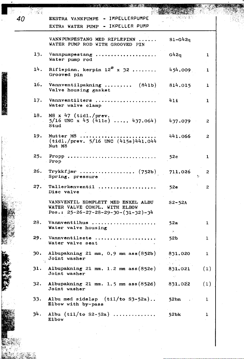
"ii!c
40 EKSTRA VANNPUMPE - IMPELLERPUMPE
EXTRA WATER PUMP - IKPELLER PUMP
VANNPUMPESTANG MED RIFLEPINN Sl-G42q
WATER PUMP ROD WITH GROOVED PIN
13. Vannpumpestang G42q 1
Water pump rad
14. Rif1epinn, kerpin 120 x 32 ..'..'" 454.009 1
Grooved pin
16. Vannventi1paknin,; ... ... ... (841b) 814.015 1
Va1ve housin,; gasket
17. Vannventi1ters ..' ". 41i 1
Water wa1ve c1amp
18. M8 x 47 (tid1./prev.
5/16 UNC x 45 (411c) .. ... 437.064) 437..079 2
Stud
19. Mutter M8 441.066 2
(tid1./prev. 5/16 UNC (415e)441.044
Nut M8
25. Propp 52c 1
Prop
26. Trykkfjmr (752b) 711.026 2
Sprin,;. pressure ~
27. Ta11erkenventi1 52e 2
Disc va1ve
VANNVENTIL KOMPLETT MED ENKEL ALBU S2- 52A
WATER VALVE CO~IPL. WITH ELBOW
Pos.: 25-26-27-28-29-30-(31-32)-34
28. Vannventi1hus 52a 1
Water va1ve housin~
29. Vannventi1sete 52b 1
Water va1ve Beat
30. A1bupakning 21 mm, 0,9 mm ass(852b) 831.020 1
Joint washer
31. A1bupaknin~ 21 mmo 1.2 mm ass(852c) 831.021 (1)
Joint washer
32. A1bupakning 21 mmo 1.5 mm ass(852d) 831..022 (1)
Joint washer
I 33. A1bu med side10p {tilito S3-52a).. 52bn 1
E1bow with by-pass
34. A1bu (tilito S2-52a) '." 52bk 1
E1bow

.. "
VANNPUMPE - IMPELLERPUMPE
EXTRA WATEI{ PUMP - IMPELLER PUMP
I
SUGESLANGE KOMPLETT. (s-R69d) 51-841.035
SUCTION HOSE COMPLETE
Pos.; 35-36-41-~2
35. Slan~enippe1 ,.. (569a) 518.016 2
Hose nipp1e
36. Rermutter, 1/2"R '."".".. (511b) 512.001 2
Pipe nut 1/2" BSP
40, Slan~enippe1. 3/8" - 900 ... """'. 519.003 1
Hose nipp1e
41. Sl~n~ek1emme 17-25 mm rustfri . 921.003 2
Hose clip, stain1ess steel
42. SUl:es1an~e 1/2" x 400 .'.'.'. (869d) 841.035 1
Suction hoge
43. S.lanr;estuss 1/2" x 110 .'.'" 841.026 1
Hose
44. Rerstuss 1/2" (642e) 611.054 1
Pipe bend
45. F1ensrin~ (711c) 721.026 1
Pipe collar ~
47. Trykkrer komp1ett "'" (623i) 611;049 1
Water pipe. pump-cyl. block
55. Hodeskrue 1-110 x 35 (tid1./prev.
3/8 UNC x 1 1/4" (484c) 432..090) ... 432.010 1
56. Hodeskrue M8 x 35 (tid1./prev.
5/16 UNC x 1 1/4" (482q)432.089) ... 432.017 4
DELER FOR KOMPLETT BUNNINNTAK MT-18
PARTS FOR SEA WATER INLET COMPLETE
Pos.; 57-58-59-60-61 (S3-62a)
57. Bunnsi1 62a 1
Sea cock strainer
..". 58. Skive (762b) 721.054 2
Washer
'" 59. Mutter 1/2"R (562b) 541.014 1
.:. Nut
60. Slusekran (962c) 946.008 1
Hand whee1 cock 1/2" BSP
61. Rernippe1 1/2"R (511a) 511..050 1
Pipe nipp1e

H 3 -,--- -;"' - ~~-- 8
2-fJi~ 5
"'" I 0 I -6
4-[1.' 7
=:f171 ,~~ 1
21 _'ti"""
22
I ./ oW ° 9
20 -S-( ,
18 - ~ 3~ 10 11 I
-<~
~'~~ I 14 ~-I'~~~ 15
./ '" ~I - lC',,-U,/ .
I
. '" . ~ ~~, .
, ' ...;
FRESH '
WATER ""-
PUMP ,
--~ g/
1 23 ing "A"
L pos, 6S 24
--.
2 2 27
<..
20,21,2 . I I 3
I I I
° i_~- 31
° 26 ~ 32
28 J,- 33

FERSKVANNSKJ0LING
,,;I FRESH WATER COOLING SYSTEM
FERSKVANNSDEHOLD~R MED T~YKKLOI(K
FRESH WATER TANK WITH PRESSURE CAP
Pos.: 1-2-J-4-5-6-7-8 Sl-2H69A
~ UTVENDIG KJ0LER0R KOMPLETT MED
MONTERINGSTILDEH0R (MT-4) '." Sl-2G69c
,.,~ COOLER COMPLETE AND PARTS FOR
': KEEL COOLER (MT-4)
,. Pos.: 26-27-28-29-JO-J1-J2-JJ
DELER FOR UTVENDIG KJ0LER0R
(MONTERINGSTILBEH0R) MT-4
PARTS FOR KEEL COOLER
Pos.: 29-JO-J1-J2-JJ
FERSKVANNSKJ0LEANLEGG MED TERMOSTAT
OG UTVENDIG KJ0LER0R KOMPLETT '.". S2-2H69A-2H
FRESH WATER COOLING SYSTEM WITH
THERMOSTAT AND KEEL COOLER COMPLETE
Pos.: A11 t:rom 1 to JJ
1. Ferskvannsbeholder 2H69A 1
Fi-esh water tank
2. Propp, ga1v. J/4" R .. "'.. (922a) 516.041 1
Prop J/4" ESP
J. Propp, ga1v. 1/2" R (911a) 516.0J9 1
Prop 1/2" ESP
4. Nippel, 1/'2" R , (511a) 511.050 1
Nipp1e, 1/2" BSP
TRYKKLOKKTUT KOMPLETT ~~ (Sl-969dk) Sl-949.002
PRESSURE CAP BODY COMPLETE
~ 5. Trykk1okktut ... (969dk) 949.002 1
. Pressure cap body
" 6. Gjengestuss (669L) 631.024 1
""
00
~ 8. Trykk1okk (Thermo TH2) (969d) 949.001 1
I Pressure cap
\0
I
~ 9. Termostat 55OC 945.001
.. Dehr. Thomsen X1.1J1.55.100
.,; Thermostat
'c ~ 10. Ferskvannsbeho1derpakning .. 814.006 1
0
-;- Fresh water tank gasket
Pressure cap sleeve
7. Overkok-rer ,... (669j) 611.089 1
Expansion pipe
11. Pinneskrue MlO x 78, (tidl./prev.
J/8 UNC x 70 (444d) 4J7.047) .. 4J7.107 2
Stud
,

FERSKVANNSKJfJLING
FRESH WATER COOLING SYSTEM
12. M~tter MlO 1I41.0S2
(tid1./prev. J/8 UNC (41Sg) 441.011)
Nut MlO
1J. Under1agsskive J/8" (72Jh) 72S.010 2
Washer
14. Overgangsnippel. J/8" x 1/2" R(S21i) S11.0J1 1
Reducing riipp1e
lS. Eksosflens/vannpakning. '" ..(821va) 814.oJ6 1
Exhaust f1ange water gasket
O~~fJPSRfJR KOMPLETT. Sl-611.018
BY-PASS PIPE COMPLETE
Pos.: 16-21-22
16. Omlepsrer 1/2" x SJO 611.018 (1)
By-pass pipe
R0RSTUSS KOMPLETT sl-611.019
PIPE COMPLETE
Pos.; 17-21-22
Rerstuss 1/2" x lSO 611.019 1
Pipe
RETURSLANGE KOMPLETT .. ... .(S-86geb) Sl-841.0J~
RETURN HOSE COMPLETE
Pos.: 18-20 (2 stk/pcS)-21-23
18. Returs1ange 1/2" x 900 .. 841.0J9 1
Return hose
SUGESLANGE KOMPLETT (S-869d) Sl-841.0JS
SUCTION HOSE
Pos.: 19-20-21-2J
Sugeslange 1/2" x 400 841.0JS 1
Suction hose
Slangeklemme. 17-2S mm rustfri 921.00J 4
Hoae clip. stain1ess steel
Rermutter, 1/2" ... (SLlb) S12.001 6
Pipe nut
22. Flensring (711c) 721.026 J
Pipe collar
2J. Slangenippel. . . . . . . . . . . . . . .. ( S69a) S18. 016 J
Hose nipple
24 Albupakning 21 mm, 0.9 mm ass.(8S2b) 8Jl.020 1
E1bow joint washer 1,2 mm ass.(8S2c) 8J1.021 (1)
1.S mm ass.(8S2d) 8J1.022 (1)

FERSKVANNSKJ0LING 45
FRESH WATER COOLING SYSTEM
25. A1bu med side19p 52bn 1
E1bow with by-pass
26. Utv. kj91er0r kompl.: Se side H-43.
Cooler complete. See page H-43.
27. Endestykke 2G69Cc (1)
End piece
28. Bunngjennomf9ringsnippe1 , 2G62A (2)
Cooler nipp1e
29. Mutter. 1/2" R ., (562b) 541.014 2
Nut 1/2" BSP
30. Skive (762b) 721.054 4
liasher
31. Foring Cor festek1emme 853.003 10
lJush for c1amp
32. Festek1emme 744.004 5
C1amp
33. Festeskrue B12 x 19 .'..'" (469c) 435.009 17
Screw
,
Pos.: 29-30-31-32-33 - MT-4
Se side/See page H-43
8RENNOLJESYSTEM - Fortsettelse fra side: 49
FUEL SYSTEM - Conto from page: 49
DEKKSFLENS M/SLANGE DG KLEMMER KOMPL 63.008
DECK FILLER W/HOSE AND HOSE CLIPS
Pos.: 68-69-70
~! Hose clip, stainless steel
..
.' 69. Slange 1 3/4" x 300 mm (83.7e) 841.056 1
68. Slangeklemmer, rustfri 55-70 (969gh) 921.043 4
Hose
70 Dekksf~ens mBd skru1okk 1 1/4" 63.007 1
Deck flller with cap
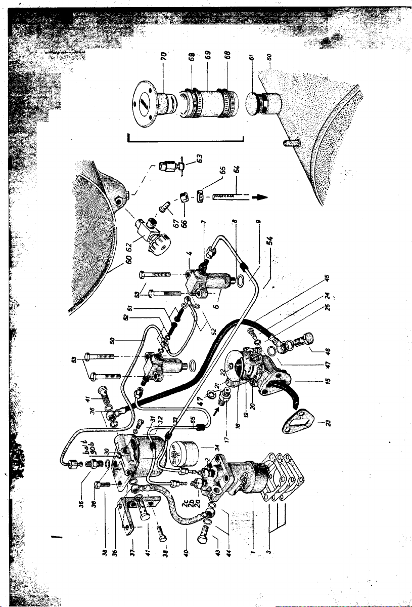
.
!f'~"
-

BRENNOLJESYSTEM - 47 c
FUEL SYSTEM
1. INNSPR0YTINGSPUMPE KOMPLETT S-2H44a
Bosch 0 414 162 978
INJECTION PUMP COMPLETE
, 2. Trykkventi1ho1der, Bosch - 1
~ '"'--~ De1ivery va1ve housing
:; ~ 2a. Trykkventi1, .. Bosch 0 418 502 015 .. G44ap 1
~ C, De1ivery va1ve
-' -
2b. E1ementinnsats, Bosch 0 418 J05 60J .. - l
Inject. pump element (6,5 mm)
2c. Trykkventi1fjmr Bosch 1 414 011 024.. 719;00J 1
Pressure spring
J. Innspreytin~s~lmpe-me11om1egg
Bosch 1 41.1 OJ8 021 O,J mm (7ltltc) 741.049 -
Bosch 1 411 OJ8 020 0,2 mm (744ca) 7~1..050 Bosch 1 41]. OJ8 022 0,5 mm (744cb) 741.051 -
DYSEHOLDER KOMPLETT S-G5JD
INJECTOR HOLDER CO~{PLETE
Pos.: 4-6-7-8-9
4. Dyseho1der. Bosch 0 4J2 297 025 -
Injector ho1deF (S-G5JD)
6. Dysemutter, Bosch 2 4JJ J14 025 -' -
Nozz1e nut
7. Rerti1kob1.m!fi1t. Bosch 2 4JJ J57 OJJ G5Jdk 1
Inj. nipp1e with filter
8. Dyse. Bosch 0 4J4 250009 G5Ji 1
Nozz1e
9. Dysepakning (85Ji) 8J1.026 2
Nozz1e joint wasner
"
~.~"'c;:~~
~~ F0DEPUMPE KOMPLETT ,. (S-944k) S-944.00J
~(( FUEL LIFT PUMP CO~{PLETE '
-~~ Pos.: 15-17-18-19-20-21-22-lt7
~~
~;;~ F0DEPUMPE-VEDLIKEHOLDSSETT.. (944ka) 944.004
'" FUEL LIFT PUMP MAINTENANCE SET
,-
..-
iJ 15. Fedepumpehus, over- og underde1 (944k) 944.00J (1)
" & Fue1 lift pump body two parts
-~ AC 795067
17. Fedepumpenippe1 1!4"R-1!2"UNF (56Ja) 511..040 1
Connection, lift pump body
18. Fedepumpesi1 (944p) 944,009 (1)
Strainer. lift pump
19. Fedepumpe1okkpakning.. (844L) 815.017 (1)
Gasket, lift p:ump cover

48 BRENNOLJESYSTEM
FUEL SYSTEM
20. Fedepumpe-membran (944n) 944.008 1
Diaphragm.lift pump
21. Fedepumpe1okk (944L) 944.006 (1)
Cover, lift pump -
22. Fedepumpe1okkskrue ..(94~lk) ~
Screw. lift pump cover 11
Fedepumpef1enspakning 0,5 mm 813.099 1
Gasket, lift pump f1ange
24. Sporskrue M8 x 16 {tidl./prev. screw
5/16 UNC x 3/1~" (435k) ... (431.033) 431.008 2
25. Tannskjve, 5/16" AZ (734h) 722.027 2
Lock washer
BRENNOLJEFILTERHUS KOMPLETT
BOSCH 0450015 003 S-G67a 1
FUEL FILTER COMPLETE
Pos.; 30-30a-31-32-3J-34
30a Filterbolt (m/pakn. 867i) ... (967i) 1
Filter bolt (w/gasket)
31. Lurteskrue ror brenno1jeri1ter(967j) 1
Bleeder screw, rue1 rilter ~
32. Lurtskruepakning. 10x6x1 (867j) 831.036 1
Fibre joint
33. Filterhuspakning.. (867a) 826.020 1
Gasket. r. rilter bowl
34. Brennoljerilterinnsats G67i 1
Fuel rilter element
35. Bosch rilternippel 1/4"R-M14 (545db) 511.036 1
Filter nipp1e 1/4" BSP-M1~
36. Kobberpakning 14 mm .'. ( 867d) 844.002 5
Gapper was her
J7. Filterholder 2H67c 1 "',
Filter holder
, UNC x 20 (434c)/Bolt (432.019) 432.150 4
38. Hodeskrue M8 x 16 (tidl./prev. 5116
~!a;
40. 01jes1ange. ri1t.-innspr.p. (844ad) 845.021 1
Fuel base. rilter-injection pump
41. Hulskrue M14 x 1.5 .. ...,... (967a) 521.011 2
Banjo nipp1e plug
43. Hulskrue M12 x 1.5 ... (944b) 521.015 1
llanjo nipple plug
44. Kobberpakning. 12 mm .. 831.018 2
Gapper washer
 Loading...