

SAB KR 175 Drake Antartica User Manual
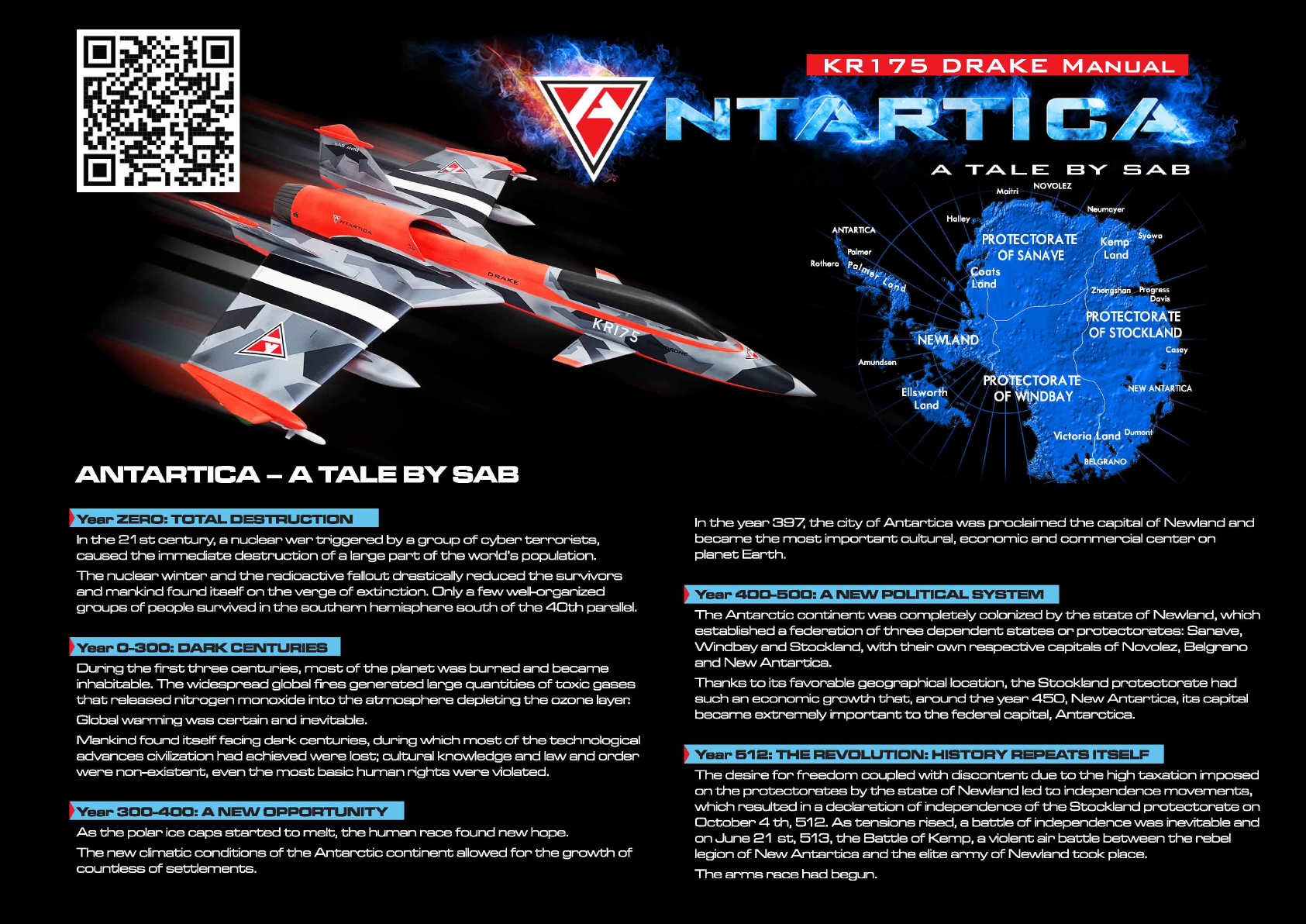

INTRODUCTION
Please read this user manual carefully, it contains instructions for the
correct assembly of the KIT.
Please refer to the web site www.sabavio.com for updates and other
important information.
VERY IMPORTANT
In the Manual bag you will find a product card with your serial number.
Please take a moment to register your kit online via our website:
www.sabavio.com
It is extremely important that you take a moment to register your airplane with us.
This is the only way to ensure that you are properly informed about changes to your
kit, such as upgrades, retrofits and other important developments. SAB Avio cannot be
held responsible for issues arising with your model and will not provide support unless
you register your serial number.
Thank you for your purchase, we hope you will enjoy your new DRAKE!
SAB Avio Team
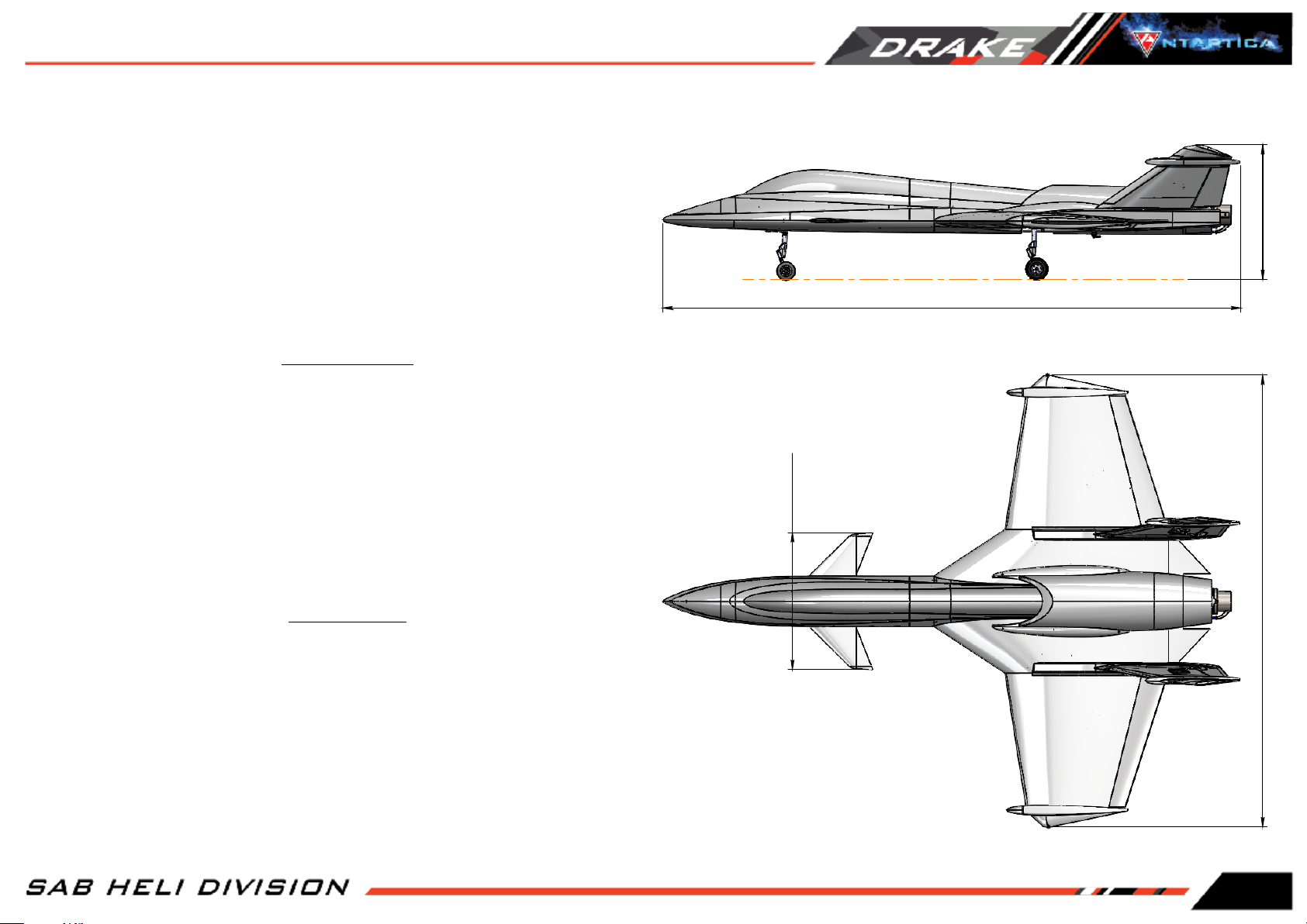
SPECIFICATIONS
Wing Span :
Wing Area :
1750mm
Around 56dm
2
521mm
2200mm
530mm
1750mm
Maximum Lenght :
RTF Weight (DRY) :
Tank Capacity :
Turbine :
2200mm
From 12 to 14kg depending on equipment
4.5 liters
From 12 to 22kg
Page 1
IMPORTANT NOTE
IMPORTANT NOTES
*This radio controlled airplane is not a toy.
*This radio controlled airplane can be very dangerous.
*This radio controlled airplane is a technically complex device which has to be built and handled very carefully.
*This radio controlled airplane must be built following these instructions. This manual provides the necessary information to correctly
assemble the model. It is necessary to carefully follow all the instructions.
*Inexperienced pilots must be monitored by expert pilots.
*All operators must wear safety glasses and take appropriate safety precautions.
*A radio controlled airplane must only be used in open spaces without obstacles, and far enough from people to minimize the possibility of accidents or of injury to property or persons.
*A radio controlled airplane can behave in an unexpected manner, causing loss of control of the model, making it very dangerous.
*Lack of care with assembly or maintenance can result in an unreliable and dangerous model.
*Neither SAB Avio nor its agents have any control over the assembly, maintenance and use of this product. Therefore, no responsibility can be traced back to the
manufacturer. You hereby agree to release SAB Avio from any responsibility or liability arising from the use of this product.
SAFETY GUIDELINES
*Fly only in areas dedicated to the use of model.
*Follow all control procedures for the radio frequency system.
*It is necessary that you know your radio system well. Check all functions of the transmitter before every flight.
*The turbine of the model is very dangerous, be aware of the danger they pose and the damage they may cause.
*Never fly in the vicinity of other people.
DAMAGE LIMITS
SAB AVIO SHALL NOT BE LIABLE FOR SPECIAL, INDIRECT OR CONSEQUENTIAL DAMAGES, LOSS OF PROFITS OR PRODUCTION OR COMMERCIAL LOSS IN ANY WAY CONNECTED WITH THE PRODUCT,
WHETHER SUCH CLAIM IS BASED IN CONTRACT, WARRANTY, NEGLIGENCE, OR STRICT LIABILITY.
Further, in no event shall the liability of SAB Avio exceed the individual price of the Product on which liability is asserted. As SAB Avio has no control over use, setup, final assembly, modification or
misuse, no liability shall be assumed nor accepted for any resulting damage or injury. By the act of use, setup or assembly the user accepts all resulting liability. If you as the Purchaser or user are
not prepared to accept the liability associated with the use of this Product, you are advised to return this Product immediately in new and unused condition to the place of purchase.
LIMITED WARRANTY
SAB Avio reserves the right to change or modify this warranty without notice and disclaims all other warranties, express or implied.
(a)
This warranty is limited to the original Purchaser (“Purchaser”) and is not transferable. REPLACEMENT AS PROVIDED UNDER THIS WARRANTY IS THE EXCLUSIVE REMEDY OF THE PURCHASER This
warranty covers only those Products purchased from an authorized SAB Avio dealer. Third party transactions are not covered by this warranty. Proof of purchase is required for warranty claims.
(b)
Limitations- SAB AVIO MAKES NO WARRANTY OR REPRESENTATION, EXPRESS OR IMPLIED, ABOUT NONIFRINGEMENT, MERCHANTABILITY OR FITNESS FOR A PARTICULAR PURPOSE OF THE
PRODUCT. THE PURCHASER ACKNOWLEDGES THAT THEY ALONE HAVE DETERMINED THAT THE PRODUCT WILL SUITABLY MEET THE REQUIREMENTS OF THE PURCHASER’S INTENDED USE.
(c)
Purchaser Remedy- SAB Avio’s sole obligation hereunder shall be that SAB Avio will, at its option, replace any Product determined by SAB Avio to be defective In the event of a defect, this is the
Purchaser’s exclusive remedy. Replacement decisions are at the sole discretion of SAB Avio. This warranty does not cover cosmetic damage or damage due to acts of God, accident, misuse, abuse,
negligence, commercial use, or modification of or to any part of the Product. This warranty does not cover damage due to improper installation, operation, maintenance or attempted repair by
anyone
Page 2
NOTES FOR ASSEMBLY
ADDITIONAL COMPONENTS REQUIRED
* Turbine from 12kg to 22kg. (with Accessories).
* Landing gear system.
* UAT.
* Batteries.
* Radio power system.
* 2 Wings servos (20x40 mm standard size, min. 20 KG).
* 2 Vector servos (20x40 mm standard size, min. 20 KG).
* 2 Rudders servos (15x35 mm mini size, min. 6 KG).
* 1 Canard servo (20x40 mm standard size, suggested 20 KG).
* 1 Steering system servo (20x40 mm standard size).
* 3 Doors servos (12x23 mm micro size).
* Accessories, extensions, tubes.
TOOLS AND ADHESIVES
*Drill with drill bits 2, 3, 4, 5mm.
*Small milling cutter for drill.
*Generic pliers.
*Hexagonal driver, size 1.5, 2, 2.5, 3 mm.
*Cyano-acrylate glue.
*Epoxy glue.
*Medium threadlocker (eg. Loctite 243).
*Soldering equipment (for electric wiring).
NOTES FOR ASSEMBLY
Please refer to this manual for assembly instructions for this model. Follow the order of assembly indicated. The instructions are divided into chapters, which are structured in a way that each
step is based on the work done in the previous step. Changing the order of assembly may result in additional or unnecessary steps.
Use thread lockers and retaining compounds as indicated. In general, each bolt or screw that engages with a metal part requires thread lock.
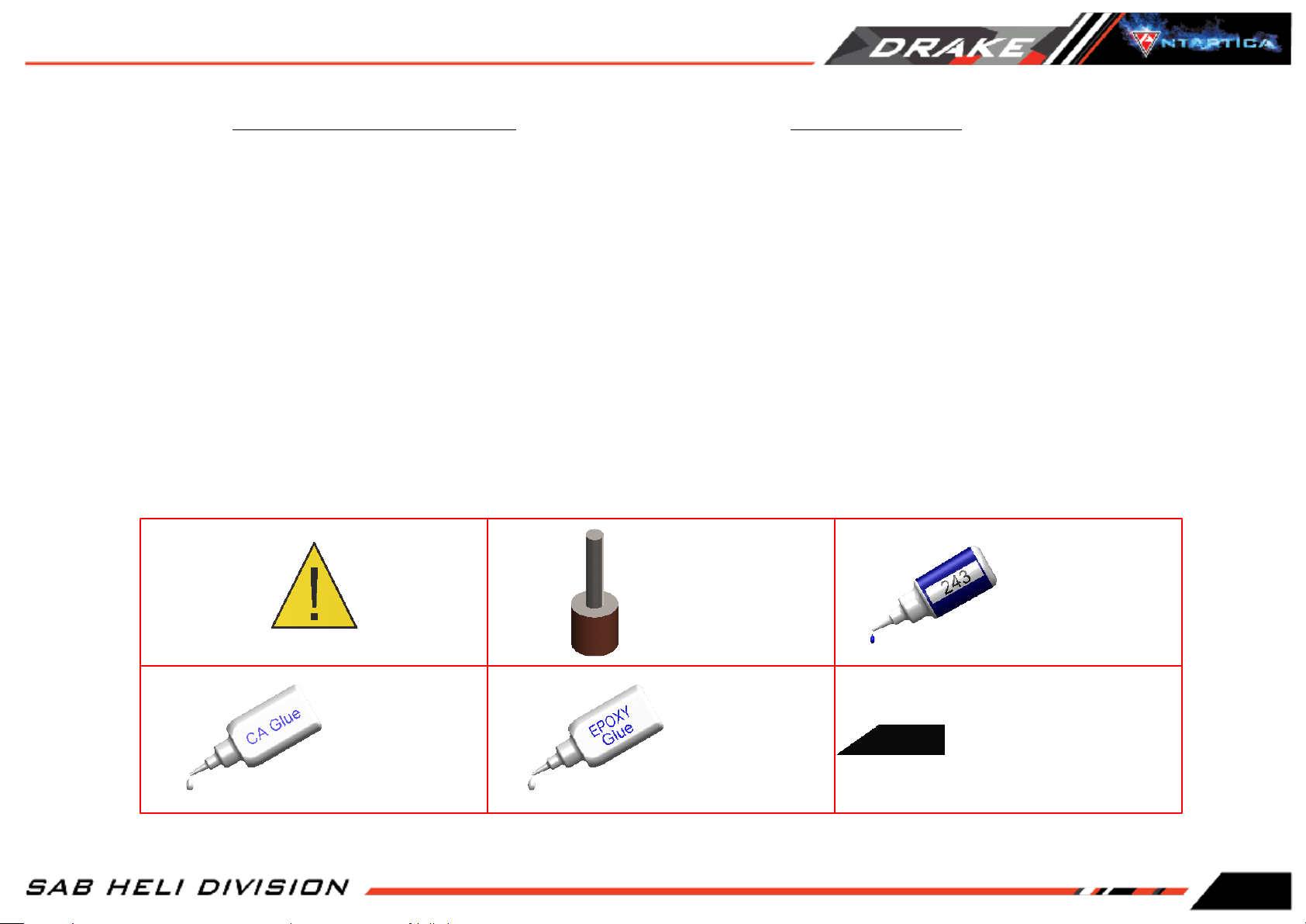
It is necessary to pay attention to the symbols listed below:
Sand and fit where
necessary
Important
Indicates that for this assembly
Use CA Glue
The assembly process is described in the following chapters. Each chapter provides you with the bag number you will need for that chapter. The information is printed in a red box in the upper right
corner of the page at the beginning of every chapter.
Use Epoxy Glue
BAGxx
phase you need materials that are:
BAG xxx.
Use Thread Locker
Medium Strength
( SAB HA116-S)
Page 3
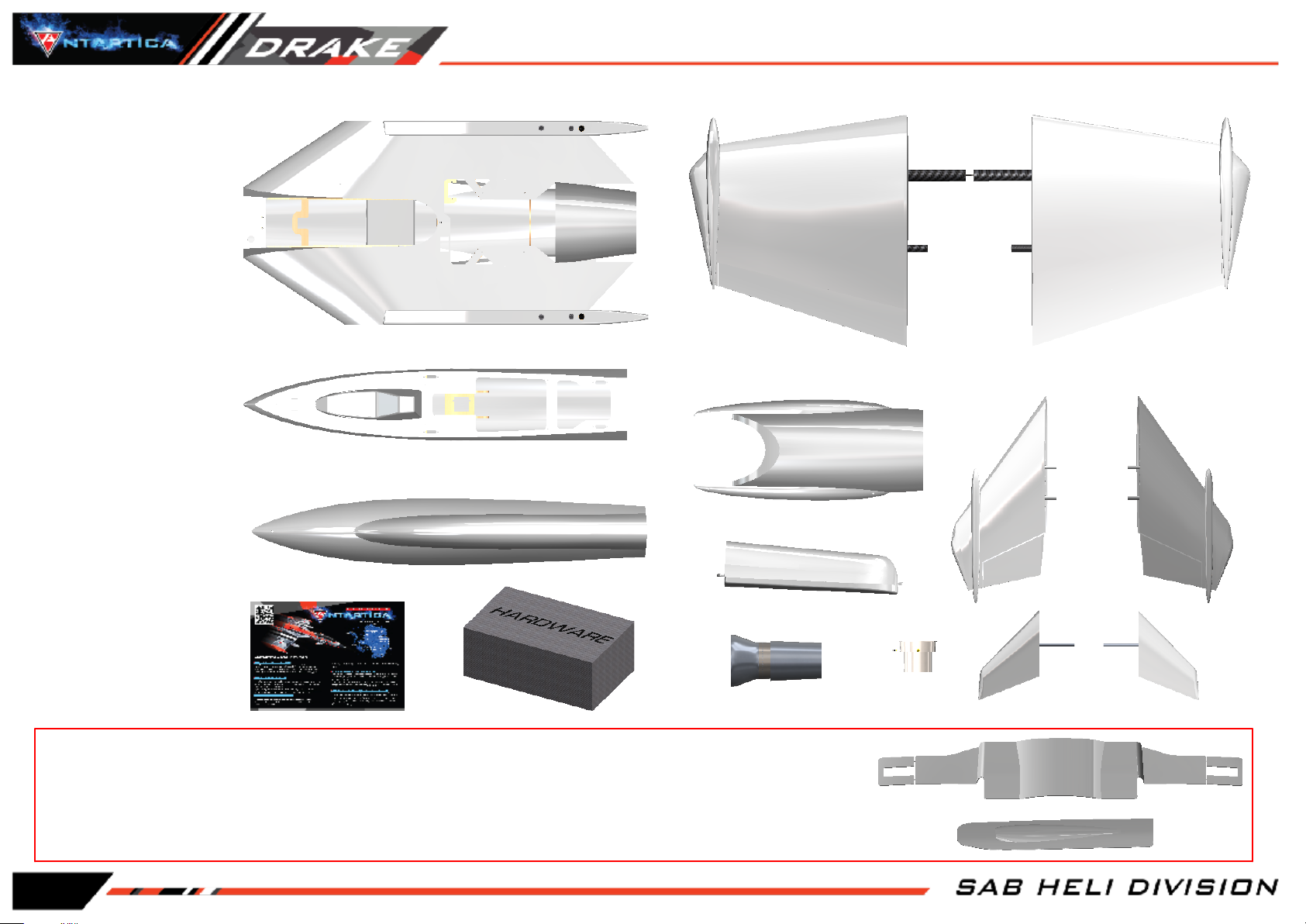
INSIDE THE BOX
* Main fuselage
* Front fuselage
* Turbine Cover
* Tank
* Cone + exhaust pipe
* Left Wings
* Right Wings
* Left Rudder
* Right Rudder
* Canopy
* Left Canard
PACKAGING
* Right Canard
* Vector
* BAGS LIST
LANDING GEAR DOORS
Inside the box you have also 1 landing gear door kit. The system needs 3 micro servos (12x23 mm).
If you want to use the landing gear doors go to page 36 and check the assembly instructions.
In this case we suggest installing the wires at the same time as installing the other wires and installing the doors before installing the landing gear.
Page 4
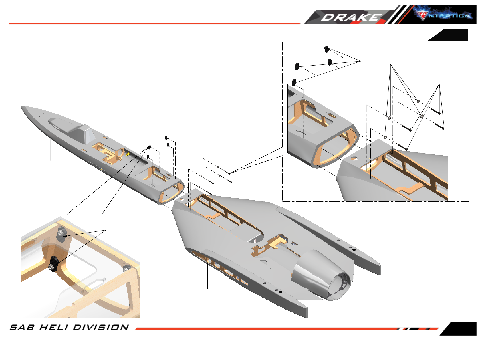
FUSELAGE CONNECTION
Connect the front part with the main Fuselage part.
BAG1
Align the two parts and tighten the screws.
If you decide to glue the 2 parts, ( best rigidity ) it need to sand the 2 joining surfaces.
Front Fuselage
(S0203-S)
S0234
[HC184]
Socket Head Cap Screw
Shoulder M4x30mm
(HC559)
S0234
Main Fuselage
(S0205-S)
Page 5
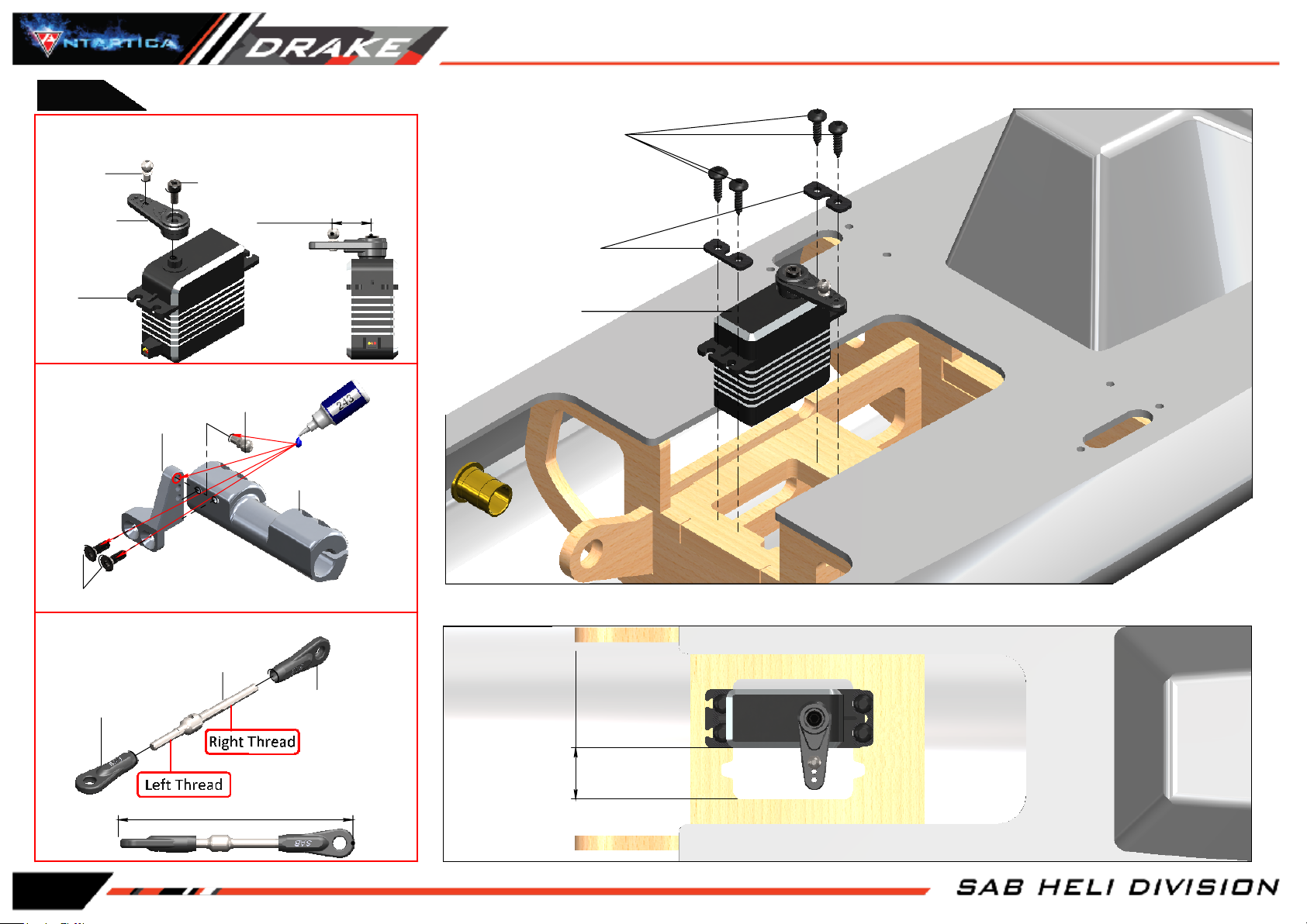
BAG2
SERVO ASSEMBLY
It is suggested metal servo horn with M3 hole.
Uniball M3
(H0065-S)
Metal Servo
Horn M3
Socket Head Cap
Screw M3x6mm
(HC044-S)
13-15mm
Self Tapping
Screw 3x12mm
(HC549-S)
NOTE:
A 2mm hole is suggested
Servo Spacer
(H0075-S)
CANARD SERVO
Servo
CANARD SERVO SUPPORT ASSEMBLY
Uniball M3
(H0065-S)
Canard Servo Arm
Canard Servo Support
(S0023-S)
Flat Head Cap Screw M3x10mm
(HC134-S)
LINKAGE ASSEMBLY
Linkage M3x50mm
(H0417-S)
Ball Linkage M3
(H0402-S)
SERVO
ASSEMBLY
Ball Linkage M3
(H0402-S)
17-18mm
Page 6
Approx 81mm

CANARD INSTALLATION
BAG2
Canard SX
(S0201-S)
Washer
10x
(HC230-S)
16x1mm
Socket Head Cap
Screws M4x15mm
(HC103-S)
LINKAGE
ASSEMBLED
CANARD SERVO
SUPPORT ASSEMBLY
Washer
10x
(HC230-S)
Canard DX
(S0202-S)
16x1mm
NOTE:
Look for the perfect
aligment of the 2 canard.
0 0
Page 7

BAG3
SERVO VECTOR ASSEMBLY
SERVO ASSEMBLY ...x2
It is suggested metal servo horn with M3 hole.
38-42mm
Uniball M3
(H0065-S)
Socket Head Cap
Screw M3x6mm
(HC044-S)
SERVO ASSEMBLY
Self Tapping
Screw 3x12mm
(HC549-S)
NOTE:
A 2mm hole is suggested
Servo Spacer
(H0075-S)
Self Tapping
Screw 3x12mm
(HC549-S)
NOTE:
A 2mm hole is suggested
Servo Spacer
(H0075-S)
SERVO ASSEMBLY
Page 8
Metal Servo
Horn M3
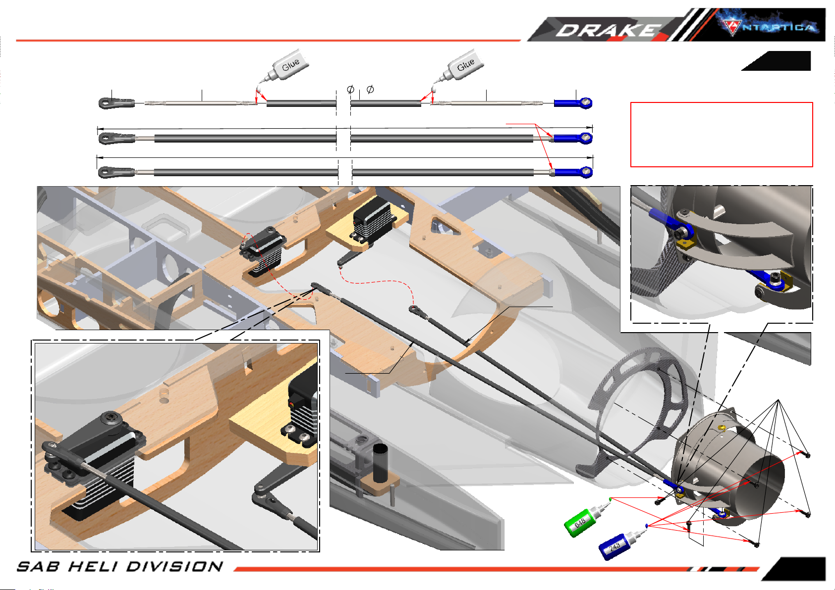
VECTOR
VECTOR LINKAGE ASSEMBLY
Plastic Ball Link
(H0403-S)
Thread rod M3x97mm
Linkage 1
Linkage 2
Epoxy (eg. UHU plus) Epoxy (eg. UHU plus)
3x
Carbon Rod
5x450mm
Thread rod M3x97mm
Carbon Rod 450 Lenght ( Full Lengh Approx 516mm)
Carbon Rod 450 Lenght ( Full Lengh Approx 536mm)
Nut M3
Linkage 1
Metal uniball M3
BAG3
NOTE:
Please allow plenty of time for the glue to
cure before inserting plastic ball link onto
the threaded rod.
Linkage 2
Socket Head Cap
Screw M3x10mm
(HC056-S)
Page 9
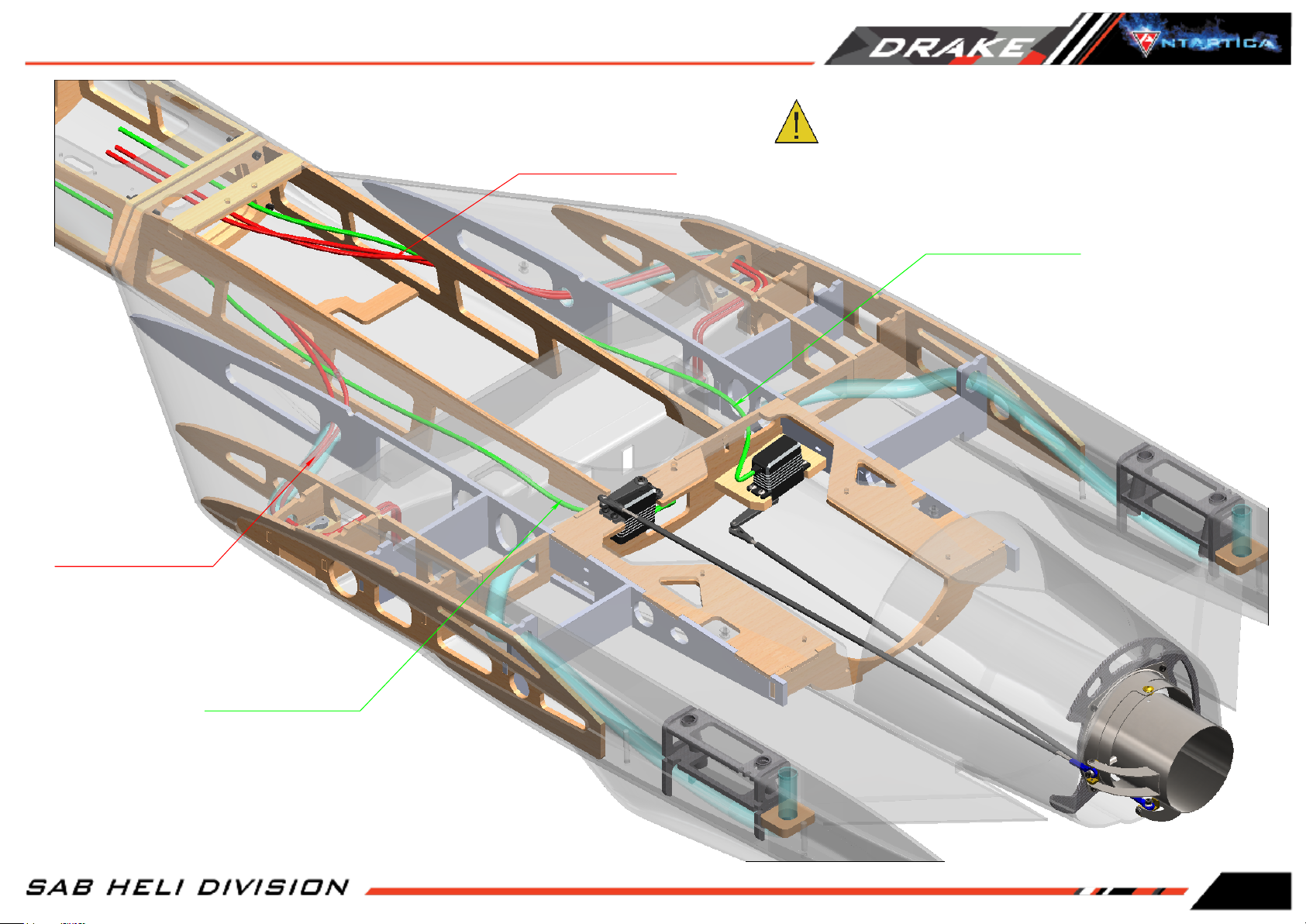
WING & RUDDER WIRE INSTALLATION
NOTE:
Protect properly all cables from contact with internal frames.
Wing wire
Rudder wire
Page 10
Wing wire
Rudder wire
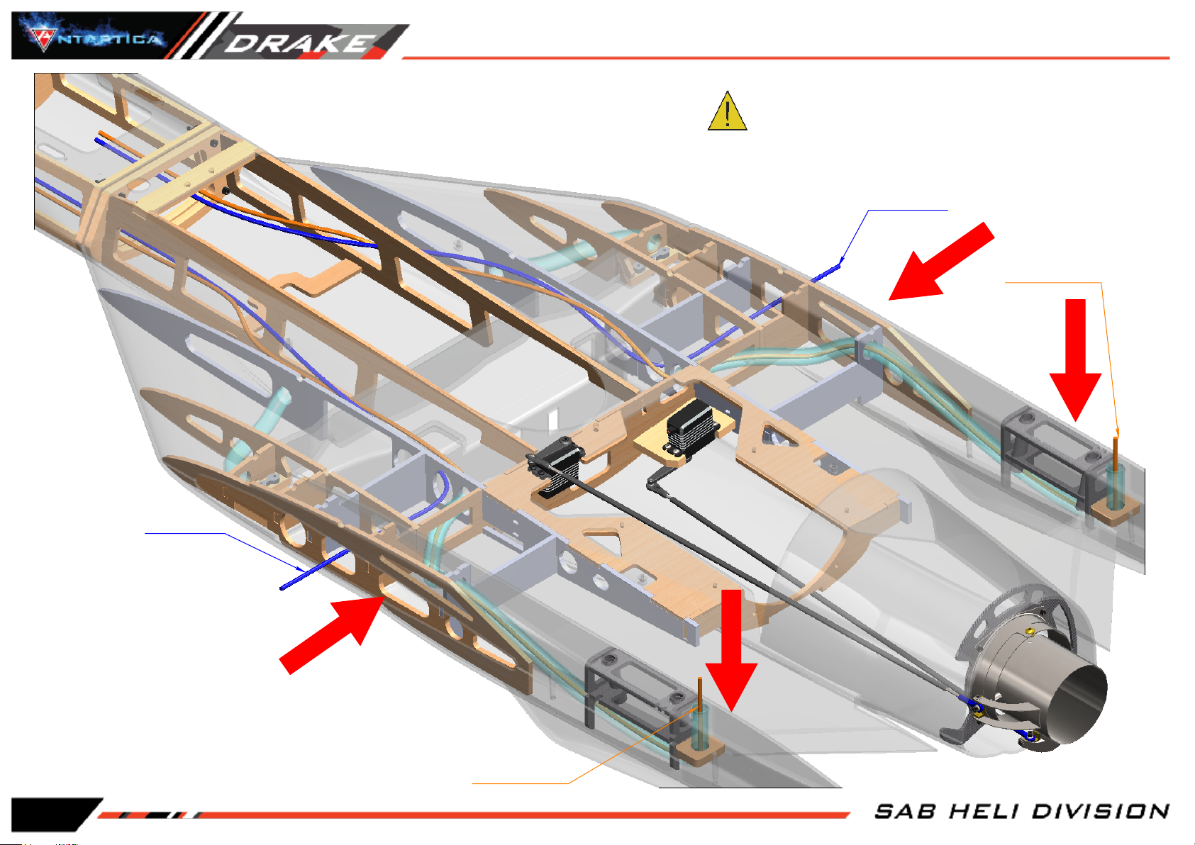
SERVO VECTOR & LANDING GEAR WIRE
NOTE:
Landing Gear Wire
Protect properly all cables from contact with internal frames.
Servo Vector Wire
Landing Gear Wire
Servo Vector Wire
Page 11
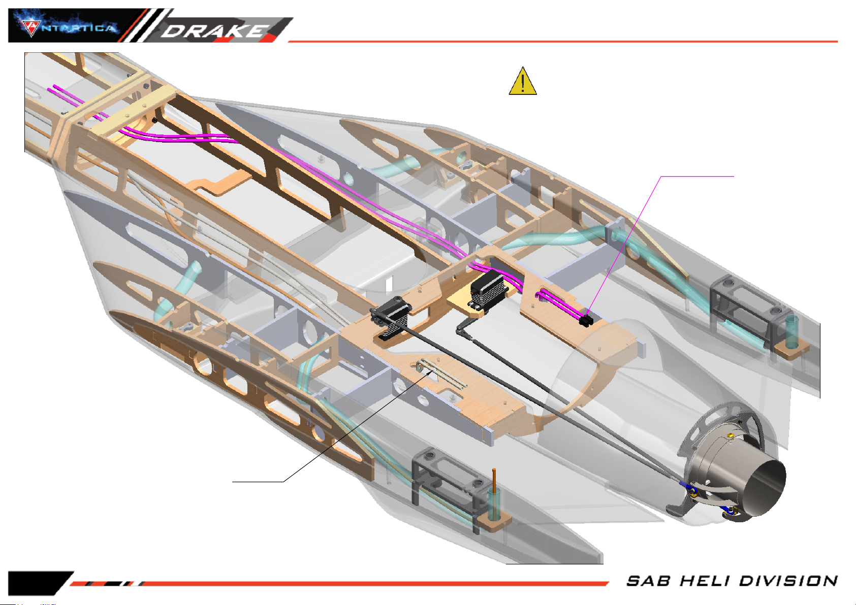
TURBINE & FUEL WIRES
NOTE:
Protect properly all cables from contact with internal frames.
Turbine Wire
Page 12
Fuel Pipe
 Loading...