

SAB Goblin 700 User Manual
GOBLIN 700 KYLE STACY EDITION
SAB HELI DIVISIONSAB HELI DIVISION
- Carefully check your model before
each flight to ensure it is airworthy.
- Consider flying only in areas
dedicated to the use of
model helicopters.
- Check and inspect the flying
area to ensure it is clear of
people orbstacles.
- Rotor blades can rotate at very
high speeds! Be aware of the
danger they pose.
- Always keep the model at a
safe distance from other pilots
and spectators.
- Avoid maneuvers with trajectories
towards a crowd.
- Always maintain a safe distance
from the model.

Goblin 700 Kyle Stacy Edition Manual
Release 1.0 - June 2015
WORLD DISTRIBUTION
www.goblin-helicopter.com
For sales inquiries, please email:
sales@goblin-helicopter.com
For info inquiries, please email:
support@goblin-helicopter.com
Attention: If you are a consumer and have questions or need of assistance,
please contact in a first time the Goblin retailer where you made the purchase
EUROPEAN DISTRIBUTION
www.sabitaly.it
For sales inquiries, please email:
sales@sabitaly.it
For info inquiries, please email:
info@sabitaly.it
Attention: If you are a consumer and have questions or need of assistance,
please contact in a first time the Goblin retailer where you made the purchase

375 mm
1388 mm
196 mm
7 – Assembling The Modules
8 – Installation of Swashplate Servos
9 – Installation of The Motor
10 – Installation of The ESC
11 – Installation of Flybarless Unit and RX
12 – Tail Assembly
1 – Serial Number
2 – Important Notes
3 – Components and Box
4 – Carbon frame Assembly
5 – Trasmission Assembly
6 – Main rotor
INDEX
13 – Installation of the Boom, Canopy
14 – Battery
15 – In flight
16 – Maintenance
17 – Exploded Views
18 – Spare Parts
//www.goblin-helicopter.com
http:
Main rotor diameter: 1582mm (with 690mm blades)
Main blade length: 690mm
Tail rotor diameter: 305mm
Tail blade length: 115mm
Main shaft diameter: 12mm
Tail shaft diameter: 6mm
Spindle diameter: 10mm
Weight including standard electronics: 4175g (excluding batteries).
Motor size: Maximum 64mm diameter, maximum height 64mm
Battery compartment: 60x58x350mm (adaptable to 75x58x350mm)
SPECIFICATIONS
It is extremely important that you take a moment to register your helicopter with us. This is the only way to ensure that you are
properly informed about changes to your kit, such as upgrades, retrofits and other important developments. SAB Heli Division
cannot be held responsible for issues arising with your model and will not provide support unless you register your serial number.
To mount the serial number tag on your helicopter, please refer to page 29.
Thank you for your purchase, we hope you enjoy your new Goblin helicopter!
SAB Heli Division
VERY IMPORTANT
Inside Box 5, you will find Bag 21. This bag contains your serial number tag. Please take a moment to register your kit online via our
web site at:
Please read this user manual carefully, it contains instructions for the correct assembly of the model.
Please refer to the web site www.goblin-helicopter.com for updates and other important information.
Page 1
Chapter 1, Serial Number
IMPORTANT NOTES
*This radio controlled helicopter is not a toy.
*This radio controlled helicopter can be very dangerous.
*This radio controlled helicopter is a technically complex device which has to be built and handled very carefully.
*This radio controlled helicopter must be built following these instructions. This manual provides the necessary information
to correctly assemble the model. It is necessary to carefully follow all the instructions.
*Inexperienced pilots must be monitored by expert pilots.
*All operators must wear safety glasses and take appropriate safety precautions.
*A radio controlled helicopter must only be used in open spaces without obstacles, and far enough from people to minimize
the possibility of accidents or of injury to property or persons.
*A radio controlled helicopter can behave in an unexpected manner, causing loss of control of the model, making it very
dangerous.
*Lack of care with assembly or maintenance can result in an unreliable and dangerous model.
*
Neither SAB Heli Division nor its agents have any control over the assembly, maintenance and use of this product.
Therefore, no responsibility can be traced back to the manufacturer. You hereby agree to release SAB Heli Division from
any responsibility or liability arising from the use of this product.
SAFETY GUIDELINES
*Fly only in areas dedicated to the use of model helicopters.
*Follow all control procedures for the radio frequency system.
*It is necessary that you know your radio system well. Check all functions of the transmitter before every flight.
*The blades of the model rotate at a very high speed; be aware of the danger they pose and the damage they may cause.
*Never fly in the vicinity of other people.
NOTES FOR ASSEMBLY
Please refer to this manual for assembly instructions for this model.
Follow the order of assembly indicated. The instructions are divided into chapters, which are structured in a way that
each step is based on the work done in the previous step. Changing the order of assembly may result in additional or
unnecessary steps.
Use thread lockers and retaining compounds as indicated. In general, each bolt or screw that engages with a metal part
requires thread lock.
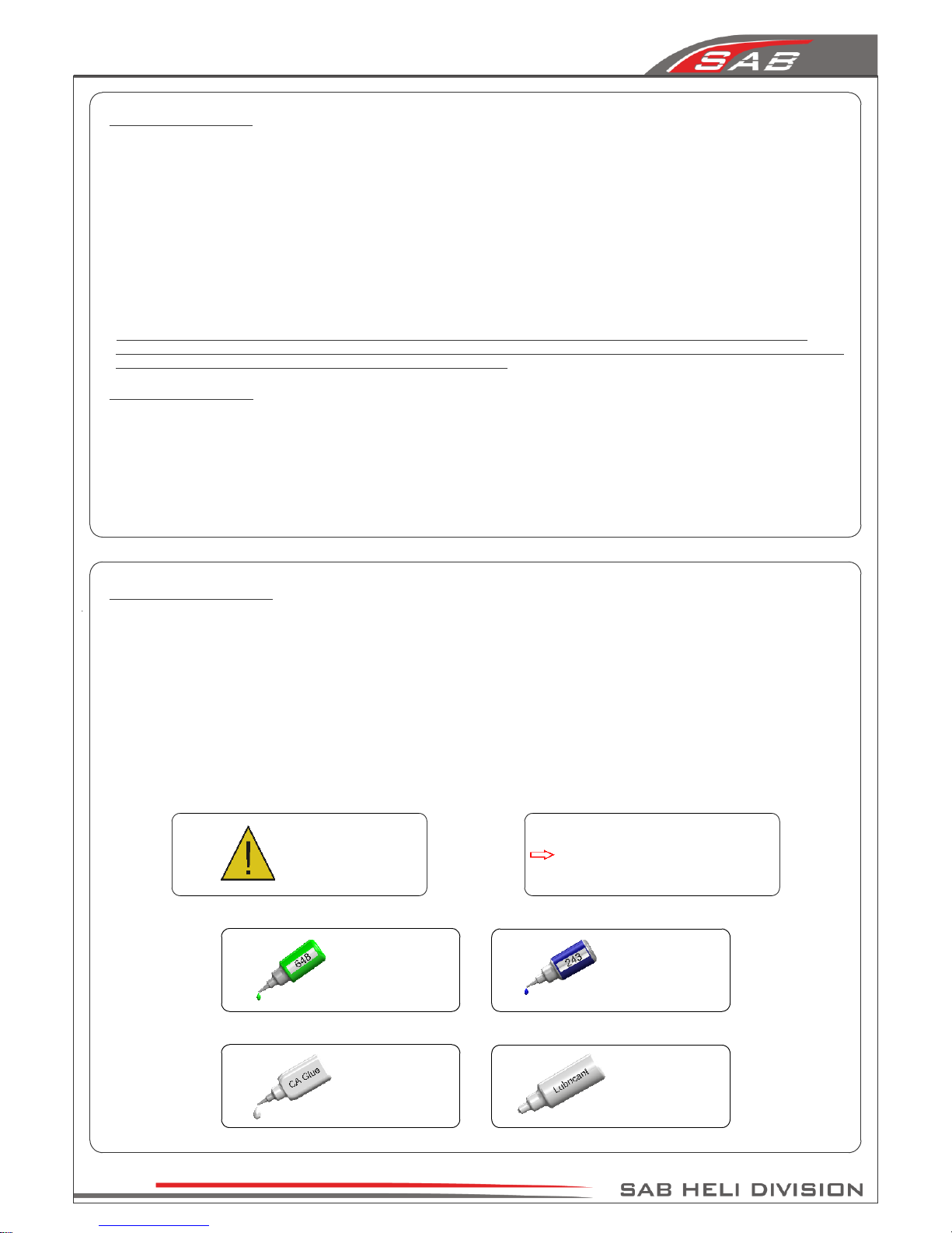
It is necessary to pay attention to the symbols listed below:
Important
Use retaining
compound
(eg Loctite 648)
Use retaining
compound
(eg Loctite 243)
Use CA Glue
Use Proper
Lubricant
Indicates that for this
assembly phase you need
materials that are in bag xx.
Bag xx
Page 2
Chapter 2, Important Notes
ADDITIONAL COMPONENTS REQUIRED
*Electric Motor: 12S – 480/520Kv
Maximum diameter 64mm,
Maximum height 64mm,
Pinion shaft diameter 6/8mm
*Speed controller: minimum 160A to be safe
*Batteries: 12S - 5000mAh
*1 flybarless 3 axis control unit
*Radio power system, if not integrated with the ESC
*3 cyclic servos
*1 tail rotor servo
*6 channel radio control system on 2.4 GHz
(See configuration examples on page 17)
The assembly process is described in the following chapters.
Each chapter provides you with the box, bag and/or foam
tray numbers you will need for that chapter. The information
is printed in a green box in the upper right hand corner of the
page at the beginning of every chapter.
TOOLS, LUBRICANTS, ADHESIVES
*Generic pliers
*Hexagonal driver, size 1.5,2,2.5,3,4mm
*4mm T-Wrench
*5.5mm Socket wrench (for M3 nuts)
*8mm Hex fork wrench (for M5 nuts)
*Medium threadlocker (eg. Loctite 243)
*Strong retaining compound (eg. Loctite 648)
*Spray lubricant (eg. Try-Flow Oil)
*Synthetic grease (eg. Tri-Flow Synthetic Grease)
*Grease ( eg. Vaseline grease )
*Cyanoacrylate adhesive
*Pitch Gauge (for set-up)
*Soldering equipment (for motor wiring)
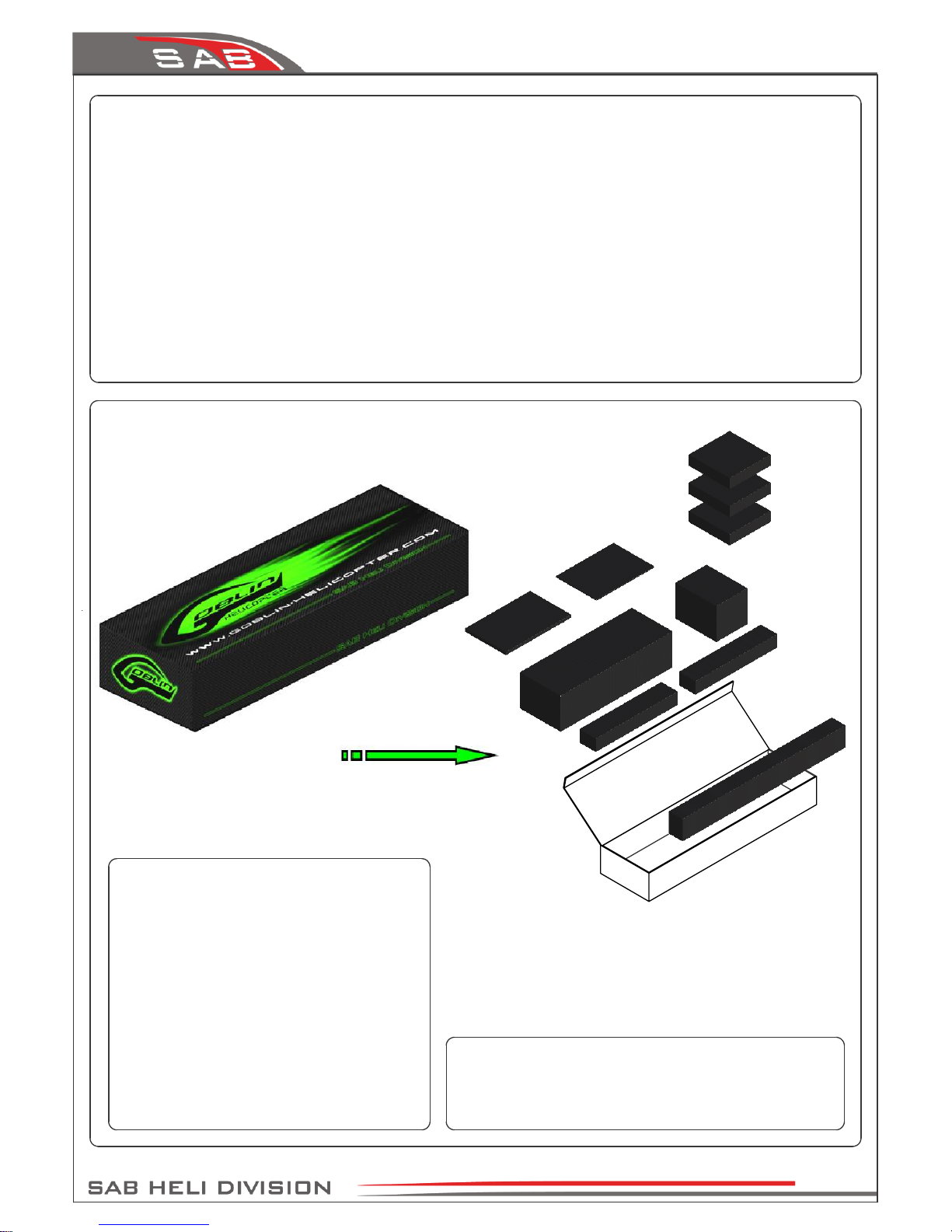
Inside the main box:
Box 2: Canopy, Blade Holder.
Box 3: Boom, Blades, Tail blades, Carbon rod.
Box 4: Mechanical parts in 4 trays:
Tray 1: Main rotor
Tray 2: Carbon frame and tail rotor
Tray 3: Transmission
Tray 4: Main structure
Box 5: Bags
Box 6: Carbon parts
Box 7: Landing Gear
Inside the main box there are:
Tray 1
Tray 2
Tray 3
Manual
BOX 6
BOX 7
BOX 2
BOX 4
BOX 5
BOX 3
Page 3
Chapter 3, Components and Box
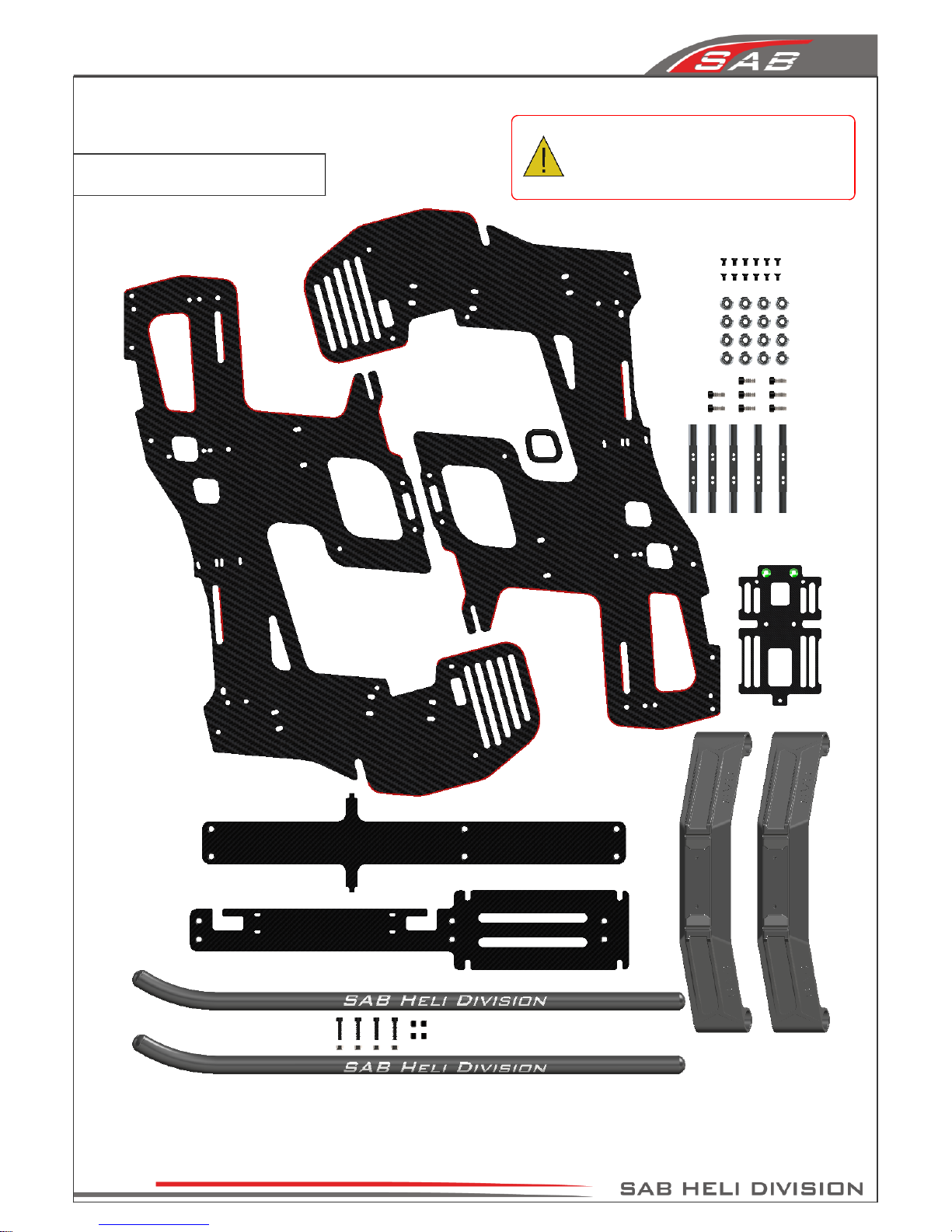
4-Carbon Frame
The manufacturing process of the carbon parts
often leaves micro-burrs and sharp edges. We
recommend de-burring the edges to minimize
the risks of electrical wire cuts, etc. Very
important in red line zone.
Page 4
Chapter 4, Carbon Frame
Flat Head Cap
Screw M2.5x5mm
(HC128-S)
ESC Support
(H0153-S)
Flat Head Cap
Screw M2.5x5mm
(HC128-S)
Flat Head Cap
Screw M2.5x5mm
(HC128-S)
Flat Head Cap Screw
M2.5x5mm
(HC128-S)
Frame Spacer
(H0003-S)
Frame Spacer
(H0003-S)
Frame Spacer
(H0003-S)
Flat Head Cap
Screw M2.5x5mm
(HC128-S)
Battery Tray
(H0002-S)
Stop Battery Plate
(H0150-S)
Socket Head Cap
Screw M2.5x8mm
(HC020-S)
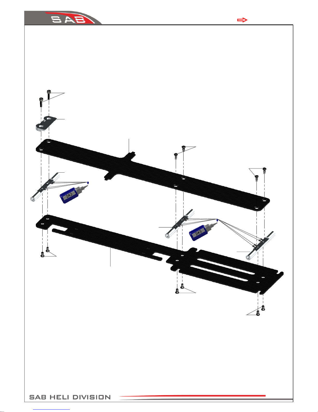
BAG 1.1, FOAM 3, BOX 6
Page 5
Chapter 4, Carbon Frame
Flat Head Cap Screw
M2.5x5mm
(HC128-S)
Frame Spacer
(H0003-S)
Socket Head Cap
Screw M3x10mm
(HC056-S)
Finishing Washer M3
(H0007-S)
ESC Support
Assembly
Main Frame 1
(H0354-S)
Flat Head Cap
Screw M2.5x5mm
(HC128-S)
Frame Spacer
(H0003-S)
ESC Support
(H0088-S)
Cable Pass
(HA010-S)
Canopy Positioners
(H0159-S)
ESC Support
Assembly
Note:
Note:
BAG 1.2, BAG 1.3, FOAM 3
Page 6
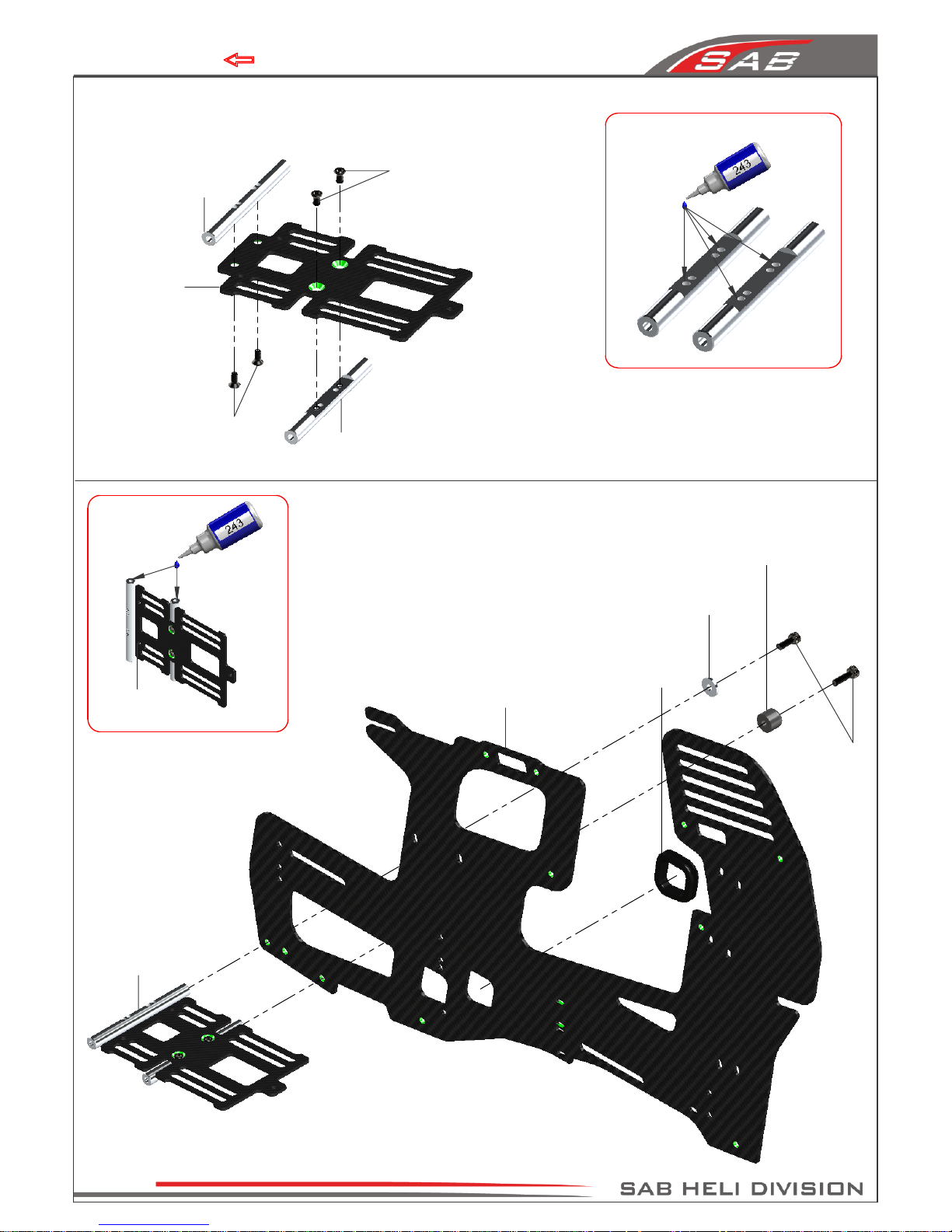
Chapter 4, Carbon Frame
Socket Head Cap
Screw M3x10mm
(HC056-S)
Finishing
Washer M3
(H0007-S)
Finishing Washer M3
(H0007-S)
Battery Support
Assembly
Finishing Washer M3
(H0007-S)
Finishing
Washer M3
(H0007-S)
Finishing
Washer M3
(H0007-S)
Main Frame Assembly
Socket Head Cap
Screw M3x10mm
(HC056-S)
Socket Head Cap
Screw M3x10mm
(HC056-S)
Bottom holes: 75mm max height batteries.
Middle holes: 70mm max height batteries.
Canopy
Positioners
(H0159-S)
Top holes: 60mm max height batteries.
Note:
Choose the position for the batteries
For the best 3D performance (with 12S-5000 batteries)
we recommend position 1
Pos 1
BAG 1.2, BOX 6
Page 7
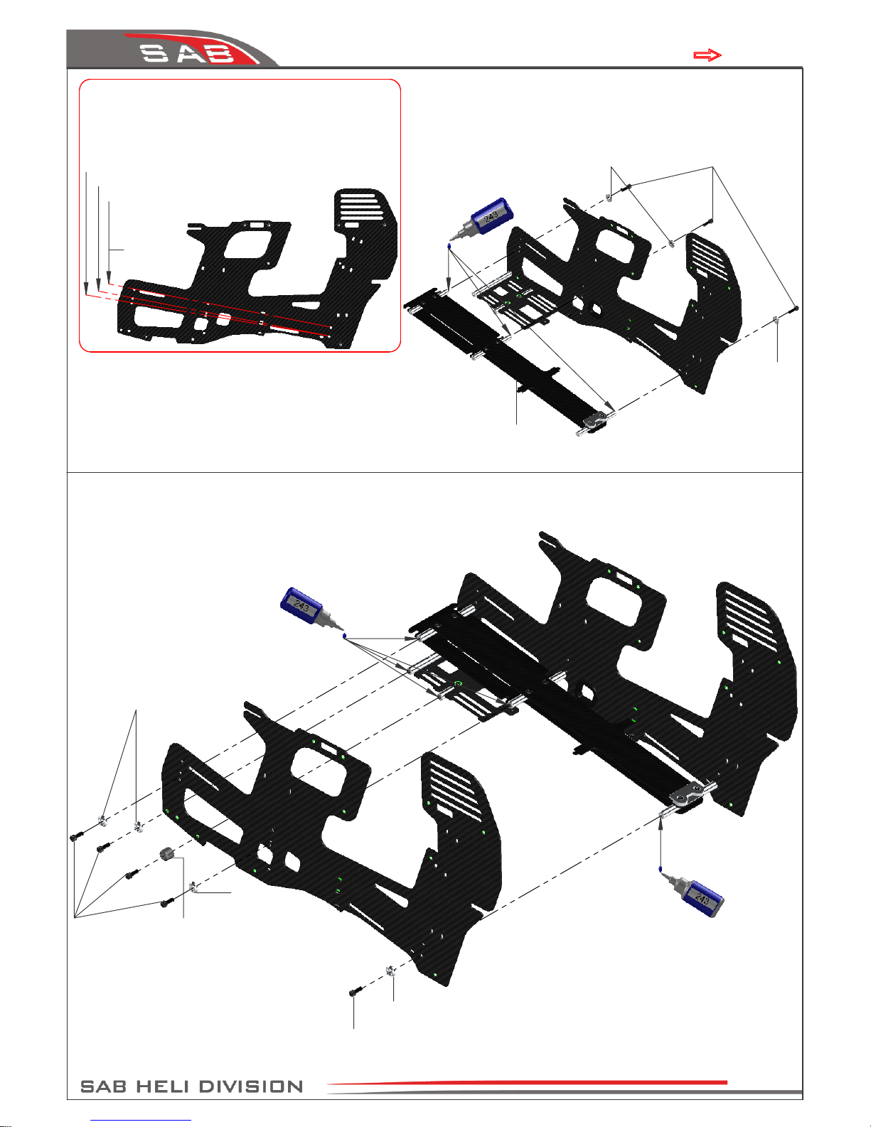
Chapter 4, Carbon Frame
Note:
You can use Super Glue to lock
the nuts in correct position
Metric Hex
Nylon Nut M3
(HC206-S)
Plastic landing gear F3C
(H0449-S)
[HC152-S]
Set Screws M4x4mm
(HC152-S)
Oring
(HC453-S)
Landing Gear Plug
(H0432-S)
Landing Gear ROD
(H0431-S)
Finishing
Washer M3
(H0007-S)
Socket Head Cap
Screws M3x16mm
(HC068-S)
Socket Head Cap
Screws M3x16mm
(HC068-S)
Finishing Washer M3
(H0007-S)
Plastic Landing Gear Assembly
Plastic Landing Gear
Assembly
BAG 2, BOX 7
Page 8
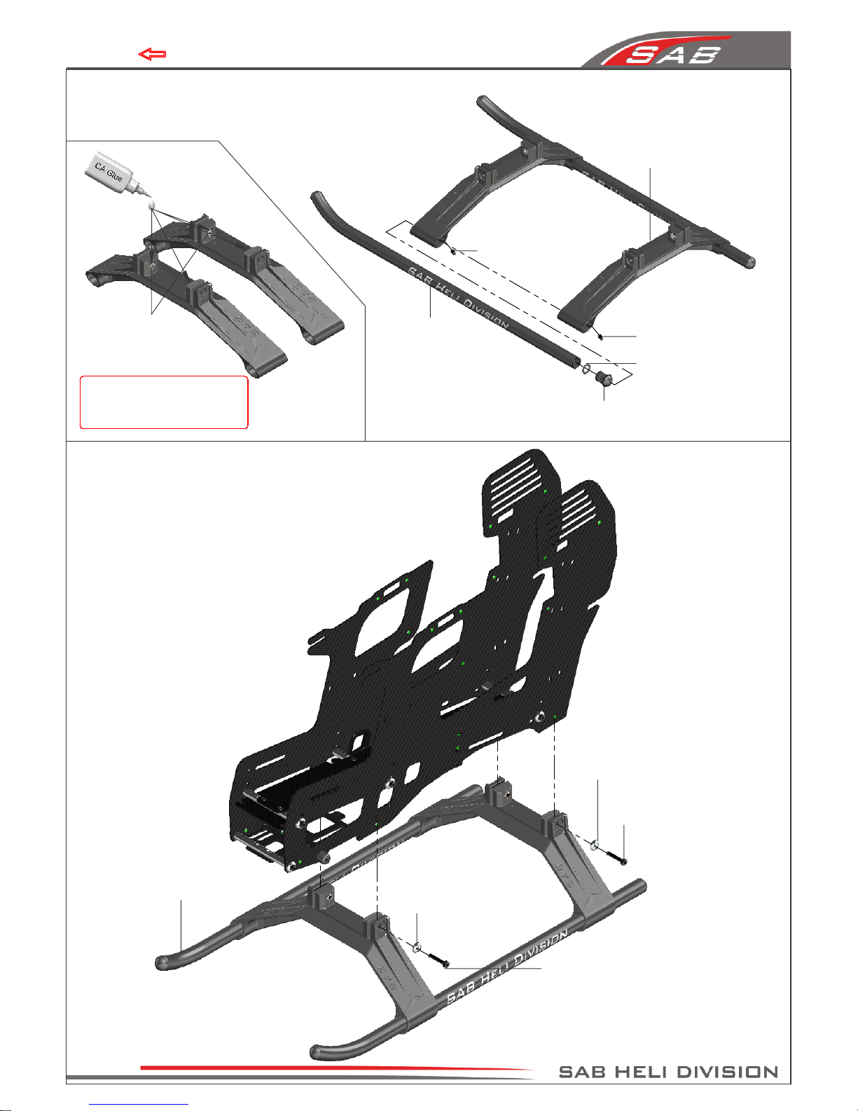
Chapter 4, Carbon Frame
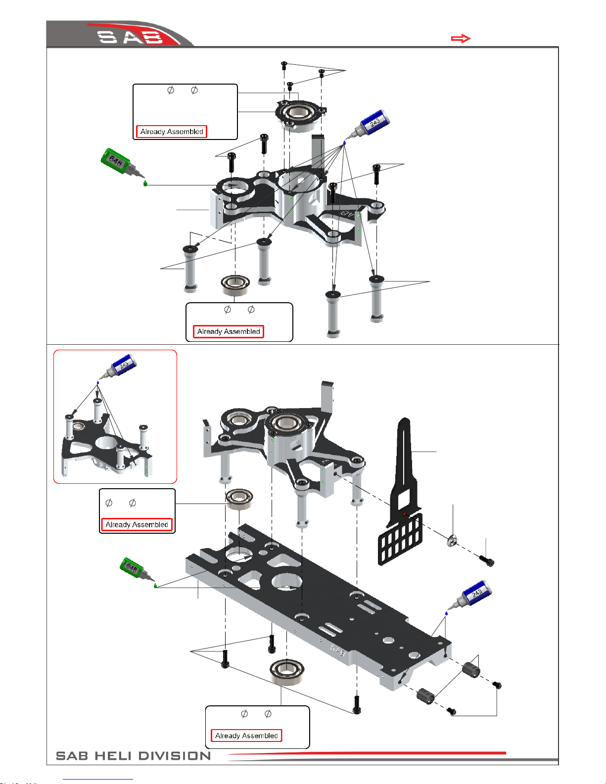
Bearing Support Assembly
(H0024-S)
Bearing
12x
24x6mm
(HC426-S)
Flat Head Cap Screw
M2.5x5mm
(HC128-S)
Socket Head Cap
Screw M3x8mm
(HC050-S)
Socket Head Cap
Screw M3x10mm
(HC056-S)
Column
(H0018-S)
Bearing
10x
19x5mm
(HC422-S)
Note:
Socket Head Cap
Screw M3x10mm
(HC056-S)
Main Structure
(H0009-S)
Antenna Guide
(H0050-S)
Button Head Cap
Screw M3x4mm
(HC038-S)
Swash plate
Anti-Rotation Guide
(H0017-S)
Bearing
12x
24x6mm
(HC426-S)
Finishing Washer M3
(H0007-S)
Column
(H0018-S)
Socket Head Cap
Screw M3x10mm
(HC056-S)
Servo Support
(H0010-S)
Bearing
10x
19x5mm
(HC422-S)
BAG 3, FOAM 1, FOAM 2
Page 9
Chapter 5, Transmission Assembly
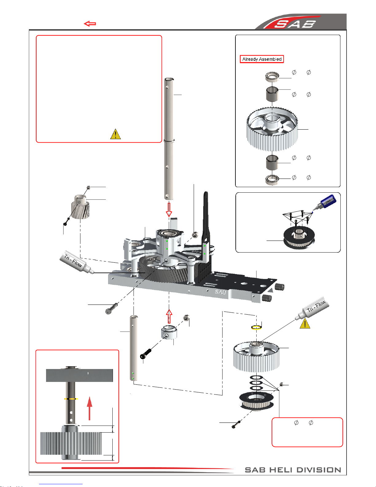
One Way Bearing
10x
14x12mm
(HC442-S)
60T Pulley Assembly
(H0171-S)
Bearing
10x
15x4mm
(HC420-S)
Socket Head Cap Screw
Shouldered M2.5x19mm
(HC033-S)
Note 1:
When you tighten the collar (
H0121-S
) on the main
shaft, ensure there is no axial play.
Push down the main shaft while pulling up the
locking collar. Tighten the screw
M4x22
at this time.
Note 2:
The pinion and gear are designed to have zero
backlash. This leads to initial “rough” rotation.
After some run in flights (
3-5 flights
) it will begin to
rotate freely, ensuring perfect contact and the
ability to transmit maximum power.
It is very important to lubricate these two
elements with a lubricant
( Dry Fluids Gear or similar).
One Way Bearing
10x
14x12mm
(HC442-S)
Bearing
10x
15x4mm
(HC420-S)
6.25
4.8
Main Shaft
(H0122-S)
Main Structure
Assembly 1
Socket Head Cap Screw
Shouldered M4x24mm
(HC111-S)
Metric Hex
Nylon Nut M4
(HC212-S)
Metric Hex
Nylon Nut M4
(HC212-S)
Socket Head Cap
Screw M4x22mm
(HC104-S)
Socket Head Cap
Screw Shouldered
M3x18mm
(HC079-S)
60T Pulley
(H0171-S)
60T Pulley Assembly
(H0171-S)
Socket Head Cap
Screw M2x12mm
(HC014-S)
Front Tail Pulley Assembly
(H0172-S)
Bush One Way
(H0110-S)
Note 2
The perfect play is 0.5mm
add or remove shim for this
Note:
Correct insertion of
the one-way pulley
37T Pulley
(H0172-S)
Metric Hex
Nylon Nut M3
(HC206-S)
19T Drive Pinion
(H0156-S)
Secondary Shaft
(H0157-S)
M4 Locking Collar
(H0121-S)
Washer
10x
16x0.2mm
(HC232-S)
Metric Hex Nylon
Nut M2.5
(HC200-S)
BAG 4, FOAM 2, FOAM 3
Main Gear
(H0405-S)
Page 10
Chapter 5, Transmission Assembly
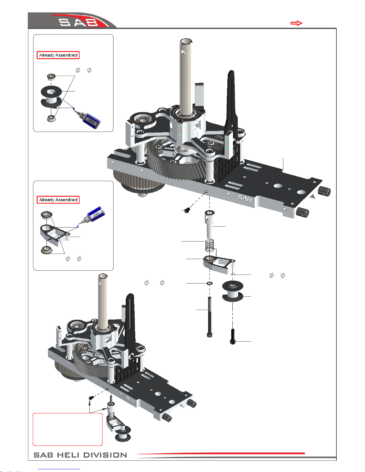
Belt Tensioner
Arm
Washer
3x
4x0.5mm
(HC176-S)
Belt Tensioner Support
(H0174-S)
Socket Head Cap
Screw M3x12mm
(HC062-S)
Tail Belt Idler Assembly
(H0174-S)
Belt Tensioner Arm
Assembly
Washer
3.2x
6x0.5mm
(HC180-S)
Socket Head Cap Screw
Shoulder M3x40mm
(HC091-S)
Main Structure
Assembly
Tail Belt Idler
Assembly
Button Head Cap
Screw M3x4mm
(HC038-S)
Belt Tensioner Arm Assembly
(H0174-S)
Note:
Position without preload.
Insert the screw in the
hole through the aluminum
support as in the picture.
Flanged Bearing
3x
7x3mm
(HC402-S)
Tail Belt Idler
[H0069]
Flanged Bearing
5x
9x3mm
(HC410-S)
Spring
de 8 / df0.5 / LL8
(HC315-S)
BAG 5, FOAM 2
Page 11
Chapter 5, Transmission Assembly
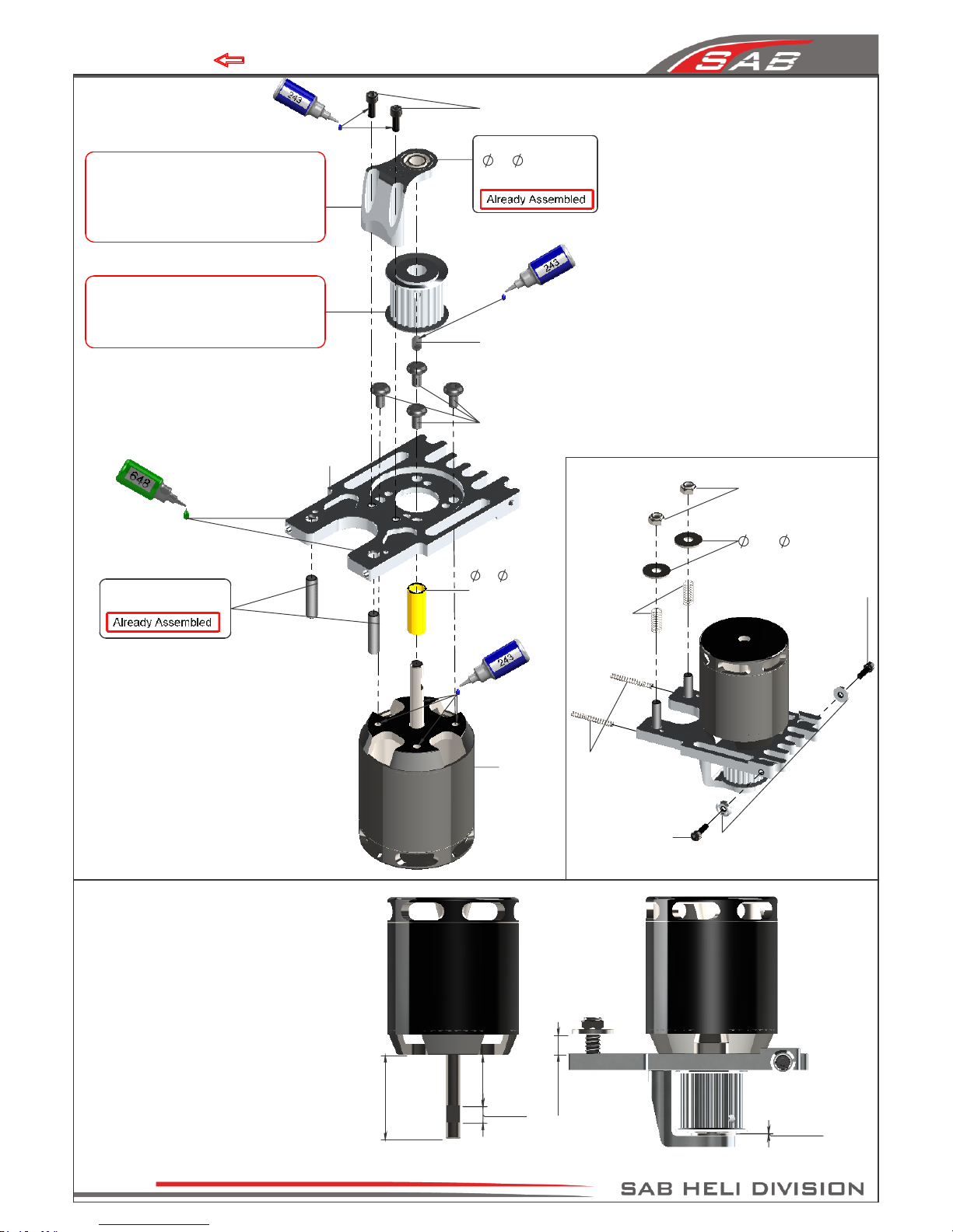
Motor Mount
(H0142-S)
Socket Head Cap
Screw M3x10mm
(HC056-S)
Finishing Washer M3
(H0007-S)
Spring
[HC310]
(HC315-S)
Washer
5.3x
15x1mm
(HC188-S)
Metric Hex Nylon
Nut M5
(HC218-S)
34mm
21mm
6mm
0.2mm
7mm
Set Screw
M4x6mm
(HC153-S)
Button Head Cap
Screw M4x8mm
(HC098-S)
20T Pulley
(H0175-20-S)
Lock motor pulley after locking H0142
(see page 17 for optional pulley selection)
Spring
HC314
(HC315-S)
Note for 6mm motor shaft
To maximize space for the batteries, it
is advisable to shorten the motor shaft.
Follow the dimensions given in this
drawing. For the cut, you can use an
electric tool like a “Dremel” with a cutoff disc.
Additionally, ensure the motor shaft
has an appropriate 'flat' for one of the
set screws.
Socket Head Cap
Screw M3x8mm
(HC050-S)
Bearing Support (H0143-S)
Lock H0142 after have locked
the motor.Motor shaft is requires
to optimize the centering. H0142
can't be used with motor shaft 8mm.
Bushing
6x
8x18mm
(H0176-S)
Use with 6mm
motor shaft.
Flanged Bearing
6x
13x5mm
(HC414-S)
Socket Head Cap
Screw M3x10mm
(HC056-S)
Set Screw M5x20mm
(HC158-S)
Motor
BAG 6, FOAM 1, FOAM 2
Page 12
Chapter 5, Transmission Assembly
 Loading...