

SAB goblin 570 kyle stacy edition User Manual


Goblin 570 Kyle Stacy Edition Manual
Release 1.0 - September 2015
WORLD DISTRIBUTION
www.goblin-helicopter.com
For sales inquiries, please email:
sales@goblin-helicopter.com
For info inquiries, please email:
support@goblin-helicopter.com
Attention: If you are a consumer and have questions or need of assistance,
please contact in a first time the Goblin retailer where you made the purchase
EUROPEAN DISTRIBUTION
www.sabitaly.it
For sales inquiries, please email:
sales@sabitaly.it
For info inquiries, please email:
info@sabitaly.it
Attention: If you are a consumer and have questions or need of assistance,
please contact in a first time the Goblin retailer where you made the purchase
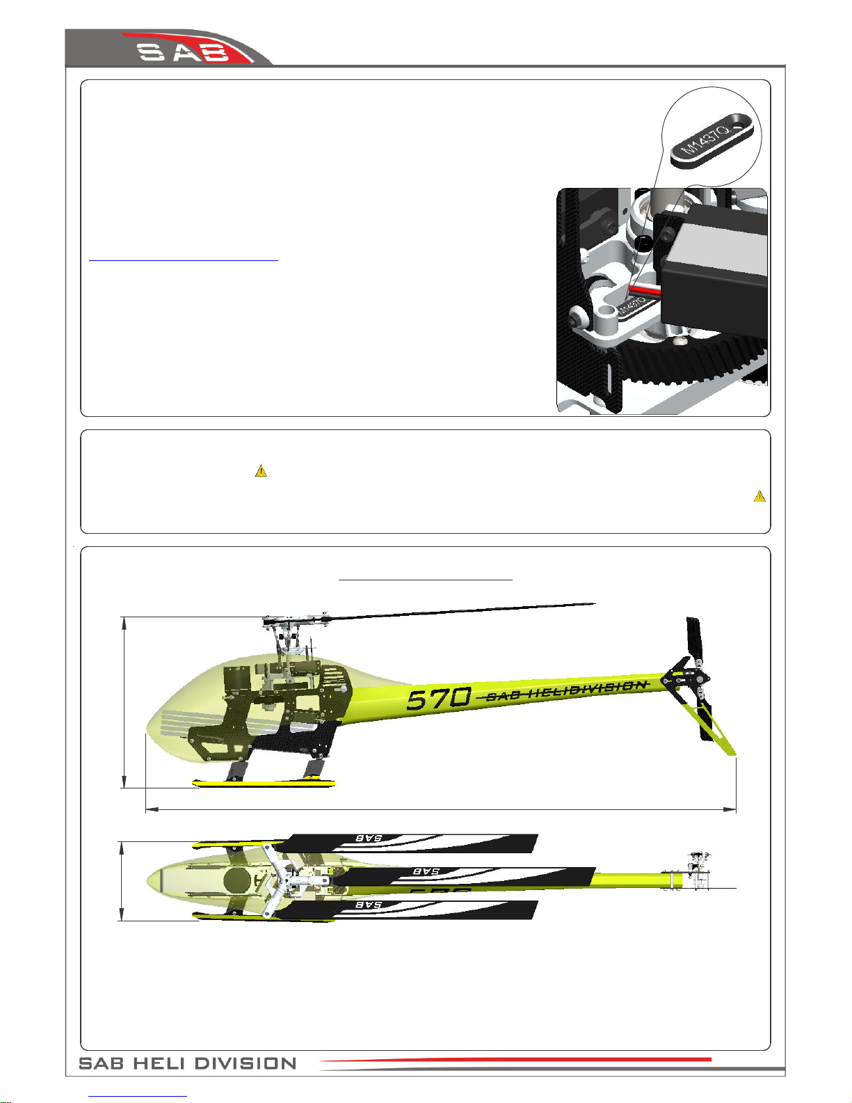
325 mm
1110 mm
150 mm
- Main rotor diameter: 1228mm (with 540mm blades)
- Main blade length: 540mm (up to 540 mm)
- Tail rotor diameter: 278mm
- Tail blade length: 104mm
- Weight including standard electronics: 2620g (excluding batteries).
- Maximum motor size: diameter 52mm, height 56mm
- Battery compartment:
* 6S–5000/5500 mAh : Max dimension 50x60x200mm.
* 12S–2600/3300 mAh : Max dimension 50x45x280mm.
SPECIFICATIONS
The Goblin
is a high performance radio controlled helicopter.
The design is original, moving away from traditional schemes, searching rationality for simplicity.
Our goal was to create a simple, high performance helicopter, with a minimum of mechanical components,
and simple maintenance.
Please read this user manual carefully, it contains instructions for the correct assembly of the model.
Please refer to the web site www.goblin-helicopter.com for updates and other important information.
It is extremely important that you take a moment to register your helicopter with us.
This is the only way to ensure that you are properly informed about changes to your
kit, such as upgrades, retrofits and other important developments. SAB Heli Division
cannot be held responsible for issues arising with your model and will not provide
support unless you register your serial number.
To mount the serial number tag on your helicopter, please refer to page 25.
Thank you for your purchase, we hope you enjoy your new Goblin helicopter!
SAB Heli Division
Very Important:
Inside Box 4, you will find Bag 9 with a red label. This bag contains your serial number
tag. Please take a moment to register your kit online via our web site at:
Chapter 13 – Installation of The Boom
Chapter 14 – Battery
Chapter 15 – Canopy & Serial Number
Chapter 16 –
In Flight / Maintenance
Chapter 17 – Exploded Views
Chapter 18 – Spare Parts
Chapter 07 – Installation Of The Servos
Chapter 08 – Assembling The Modules
Chapter 09 – Installation Of The Motor
Chapter 10 – Installation of The ESC
Chapter 11 – Installation Of The FBL and Bec
Chapter 12 – Tail Assembly
INDEX
Chapter 01 – Specifications
Chapter 02 –
Important Notes
Chapter 03 – In The Box
Chapter 04 – Carbon Frame Assembly
Chapter 05 – Trasmission Assembly
Chapter 06 – Main Rotor Assembly
http://www.goblin-helicopter.com/
Page 1
Chapter 1,
Specifications
IMPORTANT NOTES
*This radio controlled helicopter is not a toy.
*This radio controlled helicopter can be very dangerous.
*This radio controlled helicopter is a technically complex device which has to be built and handled very carefully.
*This radio controlled helicopter must be built following these instructions. This manual provides the necessary information
to correctly assemble the model. It is necessary to carefully follow all the instructions.
*Inexperienced pilots must be monitored by expert pilots.
*All operators must wear safety glasses and take appropriate safety precautions.
*A radio controlled helicopter must only be used in open spaces without obstacles, and far enough from people to minimize
the possibility of accidents or of injury to property or persons.
*A radio controlled helicopter can behave in an unexpected manner, causing loss of control of the model, making it very
dangerous.
*Lack of care with assembly or maintenance can result in an unreliable and dangerous model.
*
Neither SAB Heli Division nor its agents have any control over the assembly, maintenance and use of this product.
Therefore, no responsibility can be traced back to the manufacturer. You hereby agree to release SAB Heli Division from
any responsibility or liability arising from the use of this product.
SAFETY GUIDELINES
*Fly only in areas dedicated to the use of model helicopters.
*Follow all control procedures for the radio frequency system.
*It is necessary that you know your radio system well. Check all functions of the transmitter before every flight.
*The blades of the model rotate at a very high speed; be aware of the danger they pose and the damage they may cause.
*Never fly in the vicinity of other people.
NOTES FOR ASSEMBLY
Please refer to this manual for assembly instructions for this model.
Follow the order of assembly indicated. The instructions are divided into chapters, which are structured in a way that
each step is based on the work done in the previous step. Changing the order of assembly may result in additional or
unnecessary steps.
Use thread lockers and retaining compounds as indicated. In general, each bolt or screw that engages with a metal part
requires thread lock.
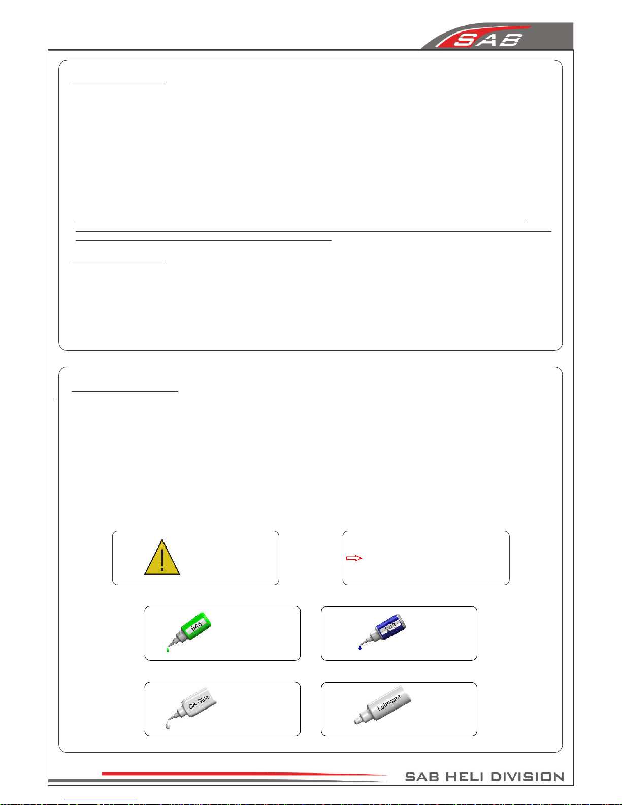
It is necessary to pay attention to the symbols listed below:
Important
Use retaining
compound
(eg Loctite 648)
Use retaining
compound
(eg Loctite 243)
Use CA Glue
Use Proper
Lubricant
Indicates that for this
assembly phase you need
materials that are in bag xx.
Bag xx
Page 2
Chapter 2, Important Notes

ADDITIONAL COMPONENTS REQUIRED
*Electric Motor: 6S–1000/1400 Kv, 12S–500/700 Kv
maximum diameter 52mm, maximum height 56mm,
pinion shaft diameter 5 - 6mm
*Speed controller: 6S minimum 100A, 12S minimum 80A
*Batteries: 6S–5000/5500 mAh, 12S–2600/3300 mAh
*1 flybarless 3 axis control unit
*Radio power system, if not integrated with the ESC
*3 cyclic servos
*1 tail rotor servo
*6 channel radio control system on 2.4 GHz
The assembly process is described in the following chapters.
Each chapter provides you with the box, bag and/or foam tray
numbers you will need for that chapter. The information is
printed in a red box in the upper right hand corner of the page
at the beginning of every chapter.
TOOLS, LUBRICANTS, ADHESIVES
*Generic pliers
*Hexagonal driver, size 1.5, 2, 2.5, 3, 4 mm
*4mm T-Wrench
*5.5mm Socket wrench (for M3 nuts)
*7mm Hex fork wrench (for M4 nuts)
*Medium threadlocker (eg. Loctite 243)
*Strong retaining compound (eg. Loctite 648)
*Spray lubricant (eg. Try-Flow Oil)
*Synthetic grease (eg. Tri-Flow Synthetic Grease)
*Grease (eg. Vaseline Grease)
*Cyanoacrylate adhesive
*Pitch Gauge (for set-up)
*Soldering equipment (for motor wiring)
Inside The Box:
Box 1: Canopy, Bag 1-A, Bag 1-B, Bag 1-C and
Blade Holder.
Box2: Optional Combo Components
Box 3: Mechanical Parts in 3 trays:
Tray 1: Head parts
Tray 2: Main structure
Tray 3: Transmission parts
Box 4: Bags
Box 5: Blades, Tail Blades, Boom, Carbon Rod
Inside the box:
Page 3
Chapter 3, In The Box
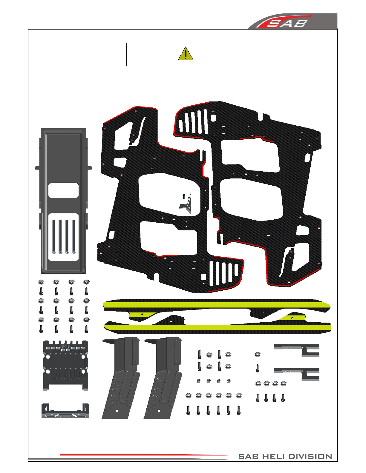
The manufacturing process of the carbon parts often leaves
micro-burrs and sharp edges. We recommend de-burring the
edges to minimize the risks of electrical wire cuts, etc.
Very Important in red line zone.
4-Carbon Frame
Page 4
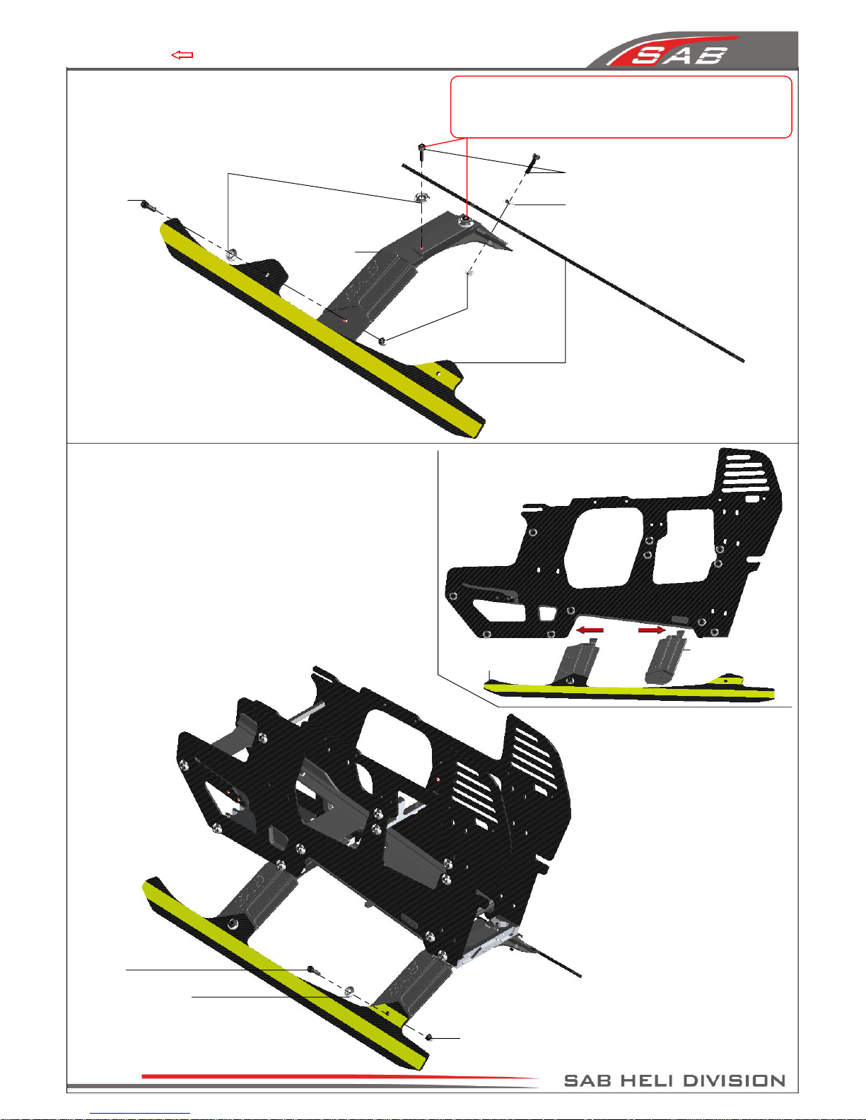
Chapter 4, Carbon Frame
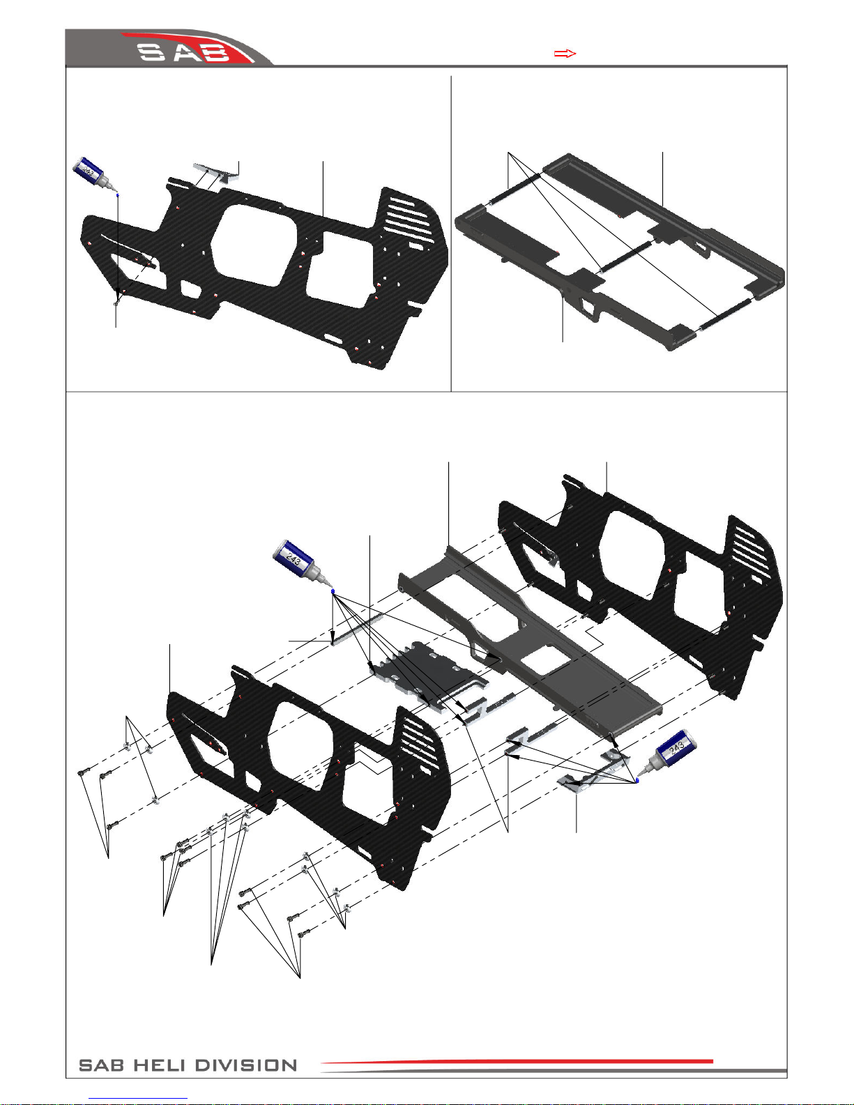
Landing Gear
Mount Front
(H0307-S)
Right Main Frame
Assembly
Right Main Frame Assembly
Main Frame
(H0290-S)
Finishing
Washer M2.5
(H0255-S)
Finishing Washer M2.5
(H0255-S)
Finishing
Washer M2.5
(H0255-S)
Socket Head Cap
Screw M2.5x8mm
(HC020-S)
Socket Head Cap
Screw M2.5x8mm
(HC020-S)
Socket Head Cap
Screw M2.5x8mm
(HC020-S)
Landing Gear
Mount Rear
(H0306-S)
Battery Support Assembly
Spacer 54mm
(H0239-S)
Battery Support Dx
(H0312_B-S)
Battery Support Sx
(H0312_A-S)
Main Frame
(H0290-S)
Battery Block
(H0256-S)
Button Head Cap
Screw M2x5mm
(HC005-S)
Battery Support
Assembly
Tail Servo
Support
(H0393-S)
Spacer 54mm
(H0239-S)
Tray 3, Bag 1, Bag 1-A7, Bag 1-B7
Page 5
Chapter 4, Carbon Frame
Metric Nylon
Nut M2.5
(HC200-S)
Metric Nylon
Nut M2.5
(HC200-S)
Socket Head Cap
Screws M2.5x8mm
(HC020-S)
Finishing
Washer M2.5
(H0255-S)
CF Yellow/White Landing
Gear (H0385-S)
Landing Gear
Support
(H0350-S)
Socket Head Cap
Screws M2.5x8mm
(HC020-S)
CF Landing Gear Assembly
Finishing
Washer M2.5
(H0255-S)
Landing Gear Support
(H0350-S)
CF Landing Gear
Assembly
Finishing Washer M2.5
(H0255-S)
Socket Head Cap
Screw M2.5x8mm
(HC020-S)
Bag 1, Bag 1-C7
By using these screws you make landing gear stronger.
However in case of hard crash you can damage the main frame.
Without using screws that landing gear is a breaking point that
avoid main frame damage
Page 6
Chapter 4 ,Carbon Frame
5-Tranmission Assembly
Page 7
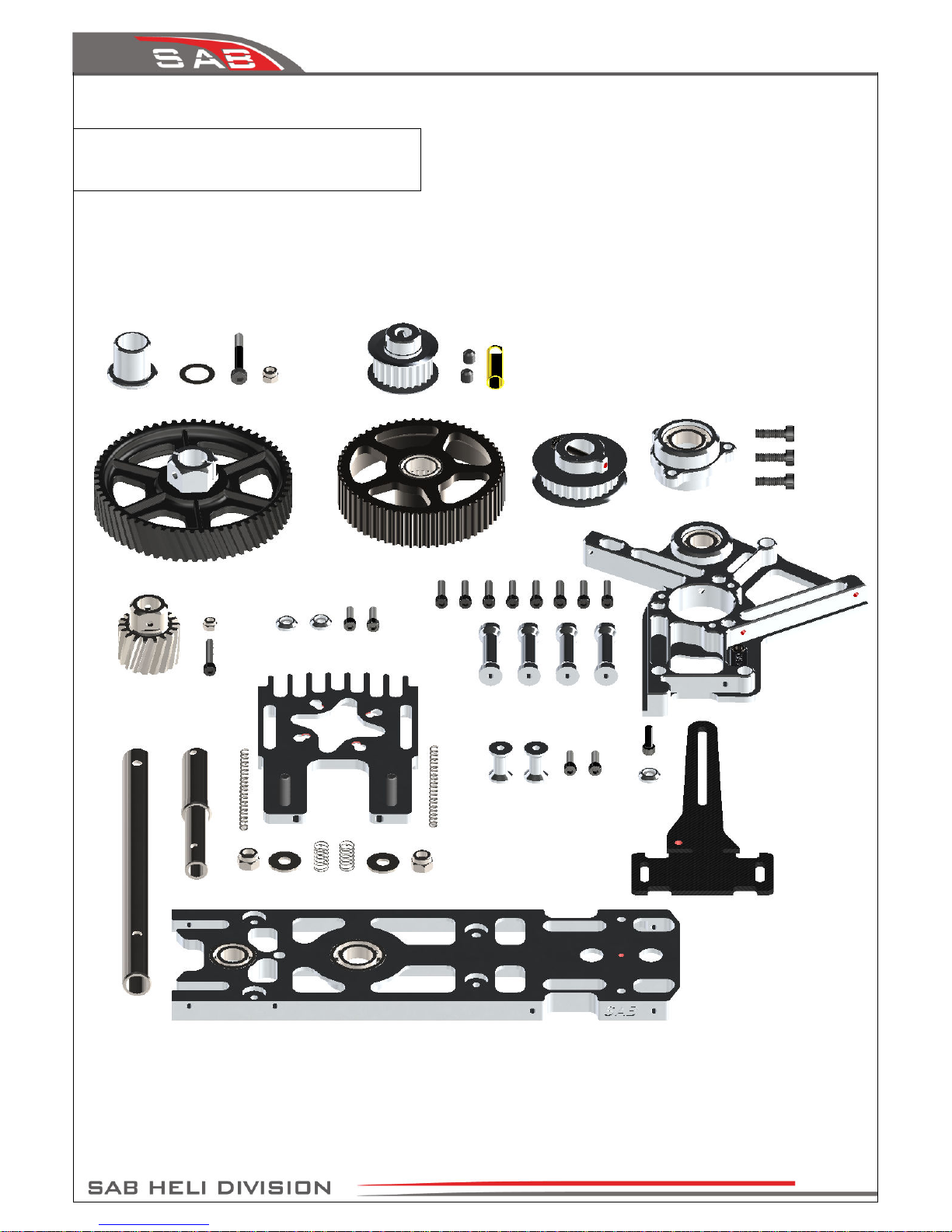
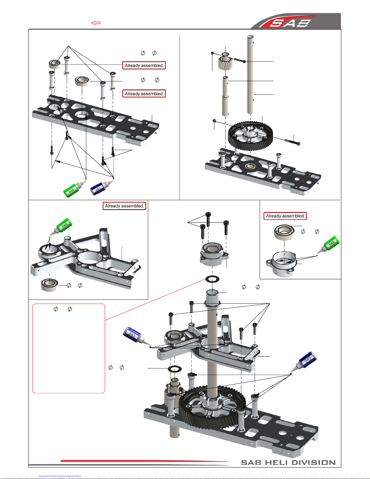
Chapter 5 , Tranmission Assembly
Socket Head Cap
Screw M2.5x15mm
(HC031-S)
Bearing
8x
16x5mm
(HC419-S)
Servo Support
(H0208-S)
Column
(H0263-S)
Bearing
10x
19x5mm
(HC422-S)
Bearing
8x
16x5mm
(HC419-S)
Socket Head Cap
Screw M2.5x8mm
(HC020-S)
Main Structure
(H0212-S)
Bearing
10x
19x5mm
(HC422-S)
Bearing Support
(H0207-S)
Bearing Support Assembly
Servo Support Assembly
Bearing Support
Assembly
Socket Head Cap
Screw M3x10mm
(HC056-S)
Spacer
10x
16x14.6mm
(H0223-S)
Socket Head Cap
Screw M2.5x8mm
(HC020-S)
Servo Support
Assembly
Washer
8x
14x0.2mm
(HC228-S)
(Use additional shims to
remove any axial play)
Socket Head Cap Screw
Shouldered M3x20mm
(HC082-S)
Metric Hex Nylon
Nut M3H4
(HC206-S)
Metric Hex Nylon
Nut M2.5H3.5
(HC200-S)
Secondary Shaft
(H0294-S)
62T Main Gear
(H0423-S)
Main Shaft
(H0296-S)
18T Pinion
(H0292-S)
Socket Head Cap
Screw M2.5x8mm
(HC020-S)
Tray 2, Tray 3, Bag 2.1
Washer
10x
16x0.1mm
(HC234-S)
Tighten the three screw M3.
After tightening, check the
axial play of the main shaft. It
is possible to reduce any axial
play by adding shims.
IMPORTANT:
Very carefully
check to make sure you can
turn the main shaft freely.
If you feel too much friction,
you have used too many
shims, you can remove a shim
until the shaft turns freely.
Page 8
Chapter 5, Transmission Assembly
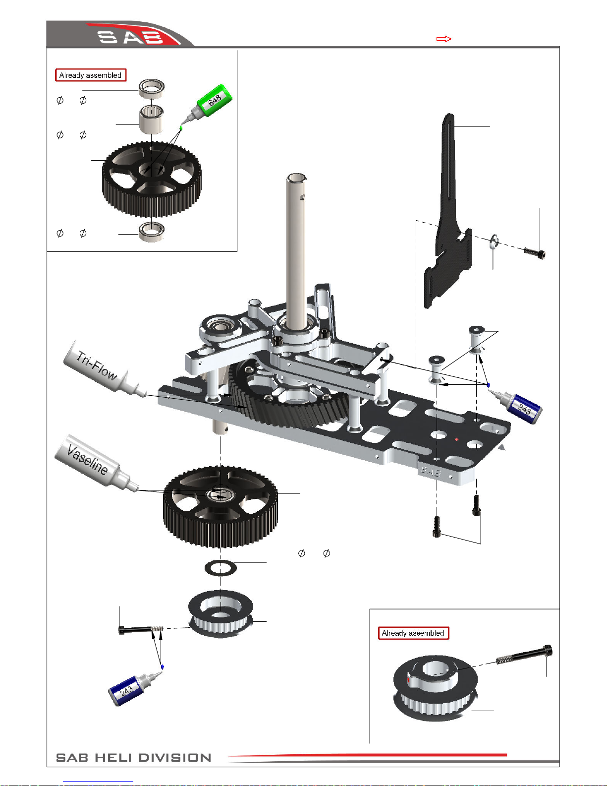
Socket Head Cap
Screw Shoudered
M2.5x19mm
(HC033-S)
Socket Head Cap
Screw M2.5x6mm
(HC018-S)
60T Pulley
(H0295-S)
One Way Bearing
10x
14x12mm
(HC442-S)
60T Pulley Assembly
60T Pulley
Assembly
28T Front Tail Pulley
Assembly
(H0304-S)
Sensor Support
(H0224-S)
Finishing
Washer M2.5
(H0255-S)
Socket Head Cap
Screw M2.5x8mm
(HC020-S)
Swashplate AntiRotation Guide
(H0401-S)
Bearing
10x
15x4mm
(HC420-S)
Bearing
10x
15x4mm
(HC420-S)
Front Tail Pulley
28T Front Tail
Pulley
(H0304-S)
(HC033-S)
Washer
10x
16x0.1mm
(HC234-S)
(Use additional shims to
remove any axial play)
Tray 3, Bag 2.2, Bag 2.3
Page 9
Chapter 5, Transmission Assembly
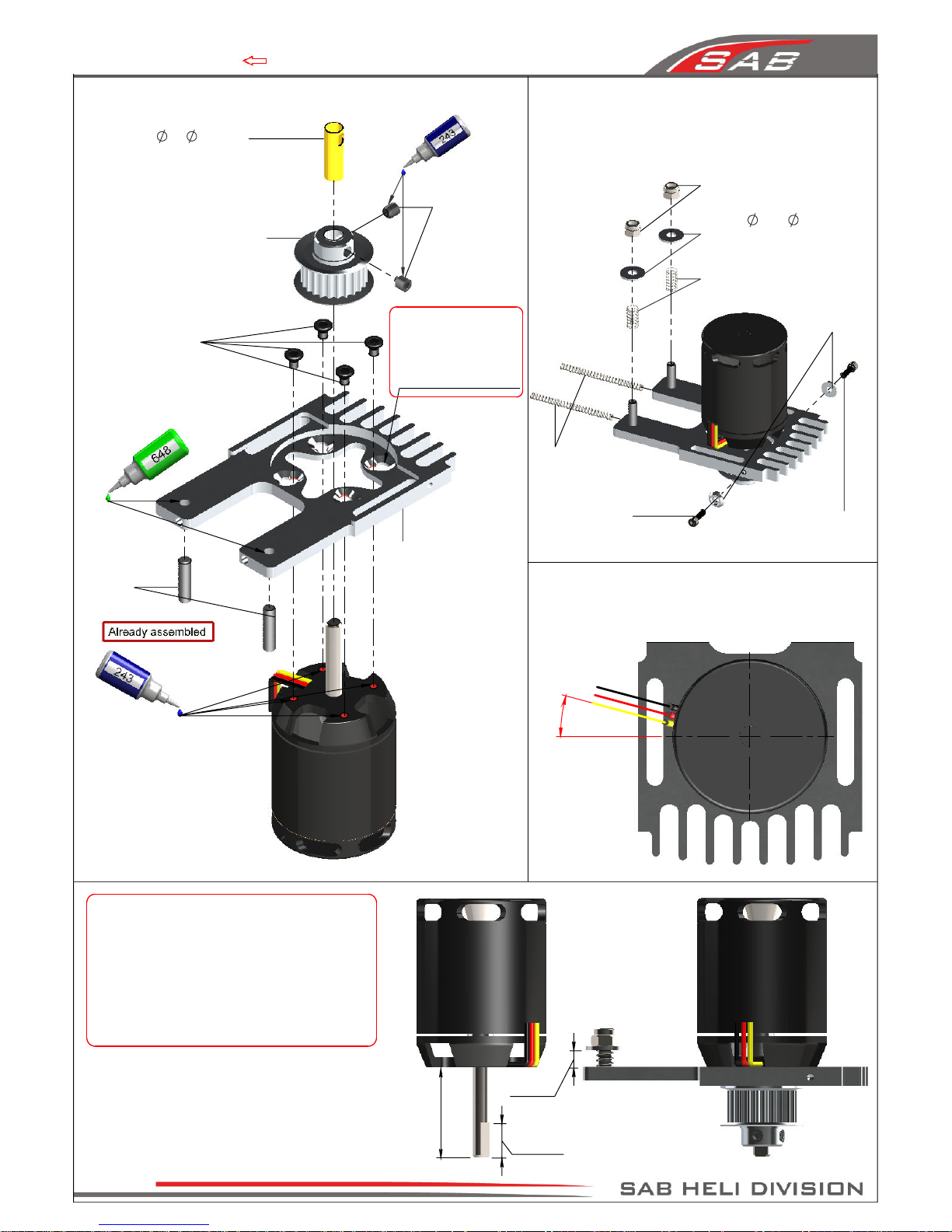
Socket Head Cap
Screw M2.5x8mm
(HC020-S)
Spring
de 3 / df 0.53 / LL35
(HC311-S)
Metric Hex Nylon Nut M4H5
(HC212-S)
Washer
4.3x
11x1mm
(HC184-S)
Spring de 5 / df 0.3 / LL6
(HC316-S)
Finishing
Washer M2.5
(H0255-S)
Socket Head Cap
Screw M2.5x8mm
(HC020-S)
Set Screw
M4x15mm
(HC154-S)
Motor Support
(H0291-S)
Set Screw
M4x4mm
(HC152-S)
Bushing
5x
6x18mm
(H0266-S)
(Needed with 5 mm motor shaft)
20T Pulley
(H0215-20-S)
(See page 16 for additional
pulleys available)
Note:
Use this hole with
motor 30x30, M4mm.
Screw M4x6mm
(HC351-S)
5 mm
28 mm
10 mm
15°
Flat Head Cap
Screw M3x5mm
(HC132-S)
Note:
To maximize space for the batteries,
it is advisable to shorten the motor shaft.
Follow the dimensions given in this drawing.
For the cut, you can use an electric tool like a
“Dremel” with a cut-off disc.
Additionally, ensure the motor shaft has an
appropriate 'flat' for one of the set screws.
Note:
Recommended motor wiring orientation
Tray 3, Bag 3.1, Bag 3.2
Page 10
Chapter 5, Tranmission Assembly
 Loading...