


Saab R6 Installation Manual
OPERATION & INSTALLATION MANUAL
Saab TransponderTech
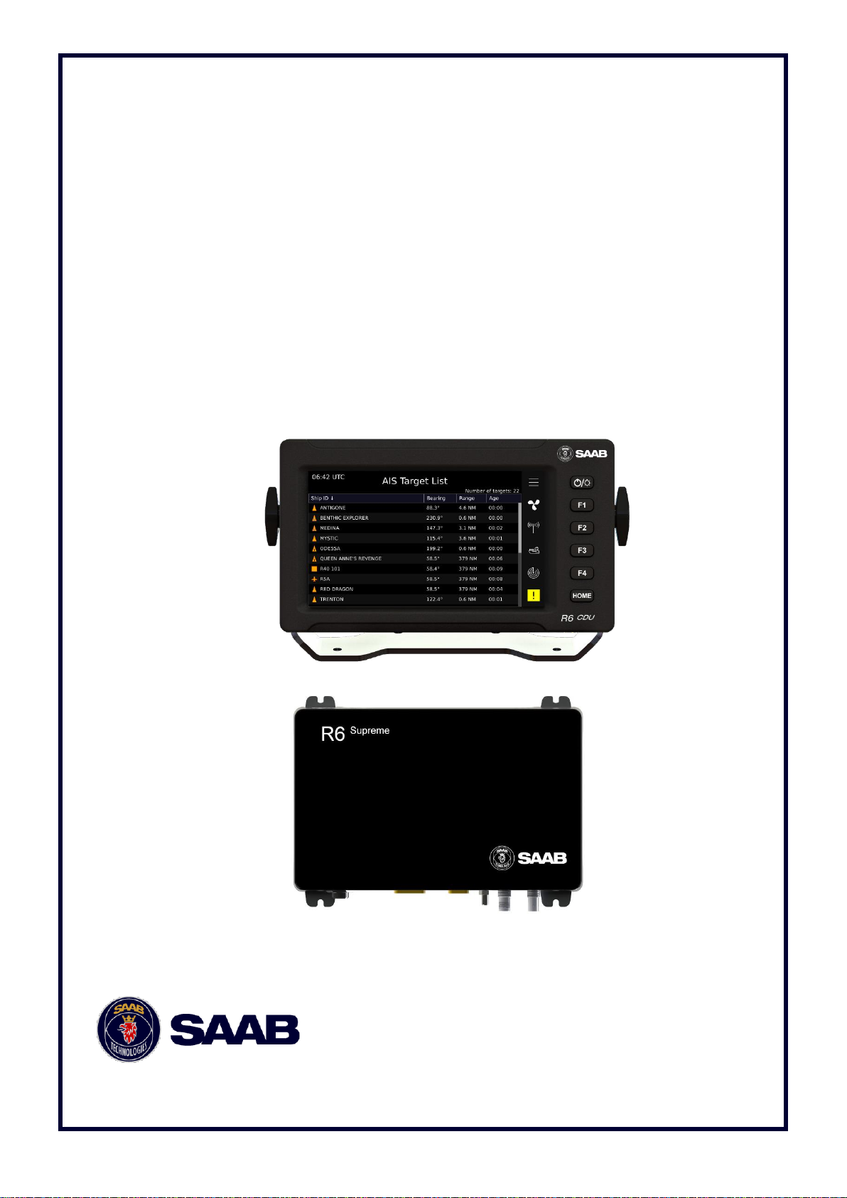
R6 SUPREME System
Class A AIS

This page is intentionally empty
R6 SUPREME System
7000 121-304, A1 Page 3
i Copyright
The entire contents of this manual and its appendices, including any
future updates and modifications, shall remain the property of Saab AB
(publ) TransponderTech at all times. The contents must not, whether in
its original form or modified, be wholly or partly copied or reproduced,
nor used for any other purpose than the subject of this manual.
Saab AB (publ) TransponderTech, SWEDEN
ii Disclaimer
While reasonable care has been exercised in the preparation of this
manual, Saab AB (publ) TransponderTech shall incur no liability
whatsoever based on the contents or lack of contents in the manual.
iii Firmware
This manual reflects the capabilities of the R6 SUPREME System with
R6 Transponder FW 1.0.2 and R6 CDU (Control & Display Unit) with
Firmware version 1.0.2.
System has the ability to be firmware updated after delivery. Therefor
the product label can specify a firmware different from the actual
firmware in the product. Current firmware versions in the system can
always be verified in the F/W info view as described in Section 7.3.
iv Manual Part Number and Revision
Part number 7000 121-304, revision A1.
v Disposal Instructions
Broken or unwanted electrical or electronic equipment parts shall be
classified and handled as ‘Electronic Waste’. Improper disposal may be
harmful to the environment and human health. Please refer to your local
waste authority for information on return and collection systems in your
area.
vi Contact Information
For installation, service, ordering info and technical support please
contact your local Saab TransponderTech representative. A list with
dealers, OEM partners and service stations can be found at our website,
listed under the corresponding product page.
www.saab.com/maritime
For the latest manual, firmware and certificates please visit:
https://www.saab.com/transpondertechsupport
R6 SUPREME System
7000 121-304, A1 Page 4
TABLE OF CONTENTS
1 Safety Instructions ......................................................................... 7
General .................................................................................................................... 7
Installation and Service .......................................................................................... 7
AIS Operational safety considerations ................................................................. 7
Compass Safe Distances ....................................................................................... 8
2 The Automatic Identification System ........................................... 9
3 System Overview ......................................................................... 10
Product Description ............................................................................................. 10
4 Installation .................................................................................... 11
Equipment part numbers ..................................................................................... 11
Equipment Installation Environment ................................................................... 12
Installation Cables ................................................................................................ 13
System interconnection overview ....................................................................... 15
Installation Procedure .......................................................................................... 16
Installing the R6 CDU ................................ ........................................................... 17
Installing the R6 SUPREME Transponder ........................................................... 18
Install the R6 Junction Box .................................................................................. 20
Mount the VHF Antenna ....................................................................................... 22
Mount the GNSS Antenna .................................................................................... 24
Electrical Installation details ................................................................................ 26
Hot Standby Installation (Future update) ................................ ............................ 31
5 Configuration ............................................................................... 32
Configuration Wizard............................................................................................ 32
System Functional Check .................................................................................... 34
AIS Configuration Menu ....................................................................................... 34
CDU Configuration Menu ..................................................................................... 43
Configuration Import/Export/Reset ..................................................................... 45
Input of Licenses .................................................................................................. 46
6 Operation ...................................................................................... 47
General usage ....................................................................................................... 47
Description of LED indicators on R6 SUPREME Transponder .......................... 47
R6 CDU HMI ........................................................................................................... 48
View Structure – Tree view .................................................................................. 51
Alerts ..................................................................................................................... 52

R6 SUPREME System
7000 121-304, A1 Page 5
Status Icons .......................................................................................................... 53
Target List ............................................................................................................. 54
Plot......................................................................................................................... 54
Voyage ................................................................................................................... 56
Towing ................................................................................................................... 56
Messages .............................................................................................................. 57
Alert List ................................................................................................................ 59
Alert Status ........................................................................................................... 60
7 Status ............................................................................................ 64
AIS Status Menu ................................................................................................... 64
CDU Status Menu .................................................................................................. 67
FW/HW Information view ...................................................................................... 67
8 Firmware Upgrade ....................................................................... 69
Upgrade Firmware in R6 SUPREME Transponder via CDU ............................... 69
Upgrade Firmware in R6 SUPREME Transponder via Web ............................... 69
Upgrade Firmware in R6 CDU .............................................................................. 70
Hard Factory reset of CDU FW ............................................................................. 71
9 Technical Specifications ............................................................. 72
R6 SUPREME Transponder .................................................................................. 72
R6 CDU .................................................................................................................. 73
R6 Junction Box ................................................................................................... 74
10 Troubleshooting ........................................................................... 75
Troubleshooting Prerequisites ............................................................................ 75
Troubleshooting with the Front Panel LED’s of the Transponder ..................... 75
Troubleshooting with Alert Messages ................................................................ 76
Troubleshooting via the CDU ............................................................................... 78
Reporting Intervals for Class A - Transponders ................................................. 81
F.A.Q ................................ ................................................................ ...................... 82
Contacting Support .............................................................................................. 82
Indication Messages ............................................................................................. 83
Long Range Definitions ................................ ........................................................ 84
11 Communication Interfaces .......................................................... 85
Serial Ports ............................................................................................................ 85
Ethernet Ports ....................................................................................................... 85
Load Capacity ....................................................................................................... 86

R6 SUPREME System
7000 121-304, A1 Page 6
12 Interpretations of ALERT Sentences .......................................... 87
Input Sentences, Alerts ........................................................................................ 87
Output Sentences, Alerts ..................................................................................... 87
13 Interpretation of Input Sentences ............................................... 89
GNSS and Sensor Input Sentences ..................................................................... 89
General Input Sentences ...................................................................................... 93
AIS Specific Input Sentences ............................................................................... 94
Long Range Input Sentences ............................................................................... 96
Proprietary Input Sentences ................................ ................................................ 97
14 Interpretation of Output Sentences ............................................ 98
General Output Sentences ................................................................................... 98
Proprietary Output Sentences (PSTT) ................................................................. 98
Long Range Output Sentences .......................................................................... 100
AIS Output Sentences ........................................................................................ 102
15 System Setups ........................................................................... 106
Installation without bridge network connection ............................................... 106
In redundant external network ........................................................................... 107
Combined AIS and Navigation system setup ................................................... 108
16 Electrical Interfaces ................................................................... 109
Wiring diagram for installation with Junction box ........................................... 109
Transponder interface details ............................................................................ 110
R6 Junction box Interfaces ................................................................................ 112
CDU Interfaces .................................................................................................... 116
17 Mechanical Drawings ................................................................. 118
Transponder Physical Size and Mechanical Drawing ...................................... 118
CDU Physical Size and Mechanical Drawing .................................................... 119
CDU Gimbal Mount Physical Size and Mechanical Drawing ............................ 120
CDU Cut-out Measurements for Panel Mount ................................................... 121
CDU Mounting Frame Cut-out and Dimensions ............................................... 122
R6 Junction Box Physical Size and Mechanical Drawing ................................ 123
GNSS Antennas – Physical Size and Mechanical Drawing .............................. 124
18 Glossary ..................................................................................... 126
Units .................................................................................................................... 128

R6 SUPREME System
7000 121-304, A1 Page 7
1 SAFETY INSTRUCTIONS
General
Saab AB (publ), TransponderTech assumes no liability for customer not complying with
requirements in this section or warnings and cautions elsewhere in this document.
This safety instruction section refers to all components of the R6 SUPREME System, referred to
as “equipment” in this section.
Installation and Service
Only qualified technicians shall do installation and servicing of equipment. Electrical fuses must be
replaced with correct types.
To prevent electrical chock hazard and damage to the equipment, the equipment shall be
connected to electrical ground. A power supply corresponding to the voltage rating of the equipment
shall be used. Failure to comply with this requirement may damage the equipment.
To ensure proper functioning of the equipment, only signal cables and antennas specified in this
document may be used. Failure to comply with this requirement may cause unexpected behavior
of the equipment.
The equipment may not in any way be modified; doing so may cause fire, shock hazard or serious
injury.
AIS Operational safety considerations
AIS Systems are very powerful tools, assisting safe navigation, which many vessels are equipped
with. AIS enables vessel identification and positioning, enhancing navigational safety.
However, it is important to know that:
Smaller vessels are more likely to not be equipped with AIS at all.
There are different classes of AIS equipment. Some non-SOLAS vessels may carry Class B
AIS equipment with 30s or more between position reports.
AIS information is only as good as the input it gets. Should any input to the AIS malfunction and
provide incorrect data (such as Heading, ROT, COG, SOG, Position), this data may still be
reported to nearby vessels. The mariner should therefore be aware that received AIS data could
be incorrect.
Each Voyage requires updating of Voyage related AIS settings
Considering this, it is important to use multiple sources of information for decision-making.
To ensure proper operation of the AIS system, make sure to view the “Alert List” for any
irregularities in system operation and verify any voyage settings are correct.
Further, in many cases there is a carriage requirement that a Class A - AIS system must be installed
and fully operating on the vessel. Some administrations may allow the AIS to be switched off when
continual operation of AIS compromise the safety or security of the vessel or where a security
incident is imminent. Turning off the AIS will result in a “Non-Functioning Time Log” entry.
R6 SUPREME System
7000 121-304, A1 Page 8
Compass Safe Distances
Measured distances according to ISO25862:2019, IEC 60945:2008
Equipment
R6 SUPREME
Transponder
R6 CDU
Safe Distance to
Standard-Magnetic-Compass
Steering-Magnetic-Compass
0,35 m
0,30 m
0,65 m
0,40 m
Reduced Safe Distance to
Standard-Magnetic-Compass
Steering-Magnetic-Compass
0,30 m
0,30 m
0,40 m
0,30 m

R6 SUPREME System
7000 121-304, A1 Page 9
2 THE AUTOMATIC IDENTIFICATION SYSTEM
The Automatic Identification System (AIS) is a safety information system that was proposed as a
worldwide standard in 1997 and adopted by IMO in 1998. The AIS system is standardized by ITU,
IEC, IALA and IMO and is subject to approval by a certification body. The first type approved AIS
transponder in the world was Saab TransponderTech’s R3 Class A Transponder in 2002.
AIS allows transceivers to automatically share static and dynamic data such as ship name, call sign,
dimensions, position and sensor information on two dedicated data links in the upper marine VHF
band. There are a number of different AIS devices that can send and receive information on the AIS
data link:
Class A Transponder – This type of transponder is used on open sea waters and is
mandatory for ships of 300 gross tonnage or more on international voyages, all cargo ships of
500 gross tonnage or more and on passenger ships.
Class B Transponder – Used on smaller vessels and pleasure crafts. It transmits with a lower
power than the Class A transponder and has lower priority on the data link. Two sub categories
exist: Class B CS with 2W output and 30s report interval, and Class B SO with 5W output and
up to 5s report interval.
Base Station – Fixed shore station that is typically connected to an AIS network to collect
information from all vessels at a certain port or shore line, and may also transmit information
such as text messages, weather data and virtual ATON markers.
Repeater Stations – Used to extend coverage range by repeating incoming messages. Can
also be implemented as a function in an AIS Base station or an AtoN station.
SAR (Search and Rescue) Transponder – Used on airplanes and helicopters in search and
rescue missions.
AtoN (Aids to Navigation) – A transceiver that is fitted on buoys and lighthouses in order to
send information about their positions.
MAtoN (Mobile Aids to Navigation) – A non‐fixed or un‐moored AtoN; but does not include
a fixed or moored buoy that is adrift from station, temporary or otherwise
Inland AIS – A European standardized extension to Class A systems for use on inland water
ways. An inland transponder has additional messages to communicate with bridges, ports and
locks and can also send some additional information that are useful on water ways such as
blue sign indication, specific hazardous cargo etc.
Locating Devices – Emergency and distress location transmitters e.g. AIS-SART, EPIRB-AIS
and MOB-AIS.

R6 SUPREME System
7000 121-304, A1 Page 10
3 SYSTEM OVERVIEW
Product Description
The basic R6 SUPREME System consists of two central parts
The R6 SUPREME Transponder
The R6 CDU (Control and Display Unit)
The R6 SUPREME Transponder is a system that consists of a VHF Data transceiver, a 48 channel
GNSS receiver, and a controlling unit. In Class A - AIS operation, the system enables at least two
AIS receiver processes and one DSC receiver process. The transmitter alternates its AIS
transmissions between the two AIS channels. The controlling unit creates and schedules data
packets (containing dynamic, static and voyage related data) for transmission based on the IMO
performance standard for AIS, and manages any data processing necessary.
The R6 SUPREME system shall be connected to the ship’s sensors as required by the installation
guidelines published by IALA and IMO. The R6 SUPREME can interface external navigation and
presentation systems that support required sentences using IEC 61162-1/2, as well as IEC 61162450 interfaces. Refer to Section 11 for more information. The R6 SUPREME is prepared for
connection to Long Range systems like Inmarsat C.
To facilitate connection to serial devices, as well as provide power fuses, installation of the R6
Junction Box is recommended.
The R6 CDU is a graphical display with touch and keypad input, type tested to meet AIS MKD
(Minimum Keyboard and Display) requirements, and is used to control and monitor the AIS system.
The colour LCD together with the touch interface provides a graphical user-friendly interface to the
system. The rubber keypads may be used for many basic operations instead of the capacitive touch
interface, in cases such as under rough sea or with gloved hands. With the R6 CDU it is possible
to plot the location of other ships, aids to navigation and search and rescue vessels. The R6 CDU
can also be used to send and receive messages, perform configuration as well as supervise the
R6 SUPREME transponder status. The front of the R6 CDU is designed to allow for a water proof
panel mount installation, and the rear of the CDU has an SD card slot for service and Firmware
updates.

R6 SUPREME System
7000 121-304, A1 Page 11
4 INSTALLATION
Equipment part numbers
The R6 SUPREME System typically consists of the R6 SUPREME transponder, the R6 CDU and
a number of optional accessories. The most common parts and accessories are listed below.
Delivery note.
NOTE: This is not a list of supplied parts, as contents may vary for each order depending on user
needs.
Name
Part number
R6 SUPREME Transponder
7000 121-500
R6 Junction box
7000 122-100
R6 CDU
7000 123-500
Power Cable
7000 121-134 alt
7000 118-077
Signal Cable DSUB-DSUB 26p 2m
7000 118-286
Signal Cable DSUB-DSUB 9p 2m
7000 123-126
Printed document set
Including:
AIS Installation Short Instruction
AIS Operator Short Instruction
Module B Certificate and DoC
R6 Supreme Document CD
7000 121-310
Ethernet Cable 5m
7000 000-525
Pilot Plug Port with Cable 5m
7000-123-128
GNSS antenna options
MA-700
AT575-68
Combined VHF/GPS Antenna
GNSS01
MGA3
7000 000-485
7000 000-135
7000 000-435
7000 000-797
7000 000-554
GNSS Antenna mast/rail mount 1" x 14
7000 000-574
VHF Antenna mast/rail mount G1"-11
7000 000-681
AIS Alarm Relay Unit incl. socket
7000 100-132
VHF Antenna BA1012 with mount
7000 000-077
R6 CDU Gimbal Mount kit
7000 123-140

R6 SUPREME System
7000 121-304, A1 Page 12
R6 CDU Flush Mount kit
7000 123-142
R6 CDU Frame Mount kit
7000 123-119
Table 1 – R6 SUPREME and accessories
Equipment Installation Environment
The table below lists the IEC 60945 equipment classification for the system.
Name
Part number
IEC 60945
installation category
R6 SUPREME Transponder
7000 121-500
Protected
R6 CDU
7000 123-500
Protected
*
R6 Junction box
7000 122-100
Protected
MA-700
AT575-68
Combined VHF/GPS Antenna
GNSS01
MGA3
7000 000-485
7000 000-135
7000 000-435
7000 000-797
7000 000-554
Exposed
Exposed
Exposed
Exposed
Exposed
Table 2 - IEC 60945 equipment classification
*An R6 CDU installed in a water sealed flush mount configuration in a panel will be water proof from
the front side. However proper ingress protection to the rear of the R6 CDU inside the panel is needed,
as the rear does not have the same water protection level.

R6 SUPREME System
7000 121-304, A1 Page 13
Installation Cables
The following cables are needed to install the R6 SUPREME System with the R6 Junction Box.
Signal Cable DSUB-DSUB 26p 2m
Marking: 7000 118-286
Type: Shielded Twisted Pair x 0.33 mm2
Length: 2 m
Connector: 2 x 26-pole H.D.D-SUB (female to male)
Flame retardant: IEC60332-1, LSZH
Interconnection: Straight connection on all pins.
Signal Cable DSUB-DSUB 9p 2m
Marking: 7000 123-126
Type: Shielded Twisted Pair x 0.25 mm2
Length: 2 m
Connector: 2 x 9-pole DSUB (female to male)
Flame retardant: IEC60332-1, LSZH
Interconnection: Straight connection on all pins.
R6 SUPREME System
7000 121-304, A1 Page 14
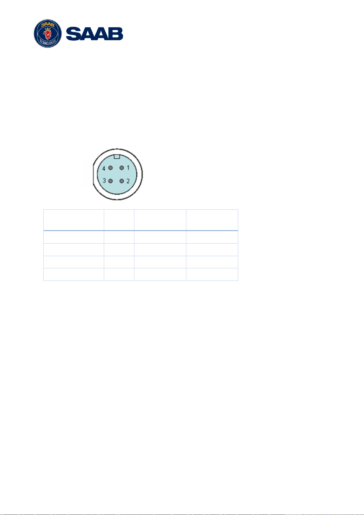
Power Cable
Marking: 7000 118-077 / 7000 123-130
Type: Unshielded 4 wire cable x 1.3 mm2 / Unshielded 2 wire cable x 1.3 mm2
Length: 2 m
Diameter: 6 mm
Connector: ConXall Mini-Con-X 6382-4SG-311 (female)
Interconnection specification:
Function
Pin
Cable Colour
Included in
7000 123-130
12 / 24 VDC
1
Red
X
0 VDC
2
Black
X
NC 3 Brown
-
NC 4 Orange
-
Table 3 – Interconnector pins
VHF Antenna Cable
Type and length: See section 4.9.2 VHF Cabling
Connector: BNC (Male)
GPS Antenna Cable
Type and Length: See section 4.10.2 GNSS Cabling
Connector: TNC (Male)
Ethernet Cable 5m
Type: Cat-6, LSZH, IEC 60332-1
Length: 5 m
Connector: RJ-45
Part number: 7000 000-525
4.3.1 Minimum cable bending radius
When installing the cables the recommended minimum bending radiuses are as follows:
R6 SUPREME System
7000 121-304, A1 Page 15
Signal and power cables: 10 times cable diameter
Coaxial cables: 5 times cable diameter
System interconnection overview
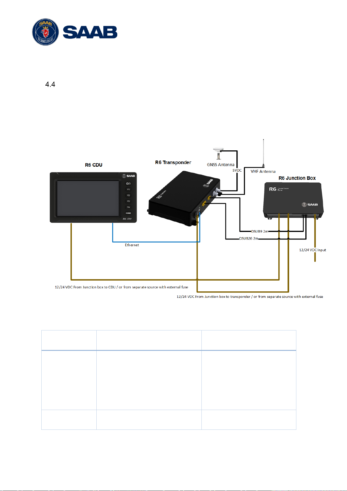
4.4.1 Basic system setup
There are numerous ways to install the system using the redundant network interfaces of the R6
SUPREME and R6 CDU. Below is a simple system setup without interface to external networks.
External sensors and systems shall in this case be connected to the R6 Junction box serial
interfaces. For alternate system setups, please see Section 15 “System Setups”
Figure 4-1- System overview
R6 Supreme Transponder
7000 121-500
R6 Junction box
7000 122-100
R6 Junction box
7000 122-100
Signal cable DSUB-DSUB 26p 2m
7000 118-286
Signal Cable DSUB-DSUB 9p 2m
7000 123-126
Power Cable
7000 118-077 alt 7000 123-130
-
R6 CDU
7000 123-500
Ethernet Cable 5m
7000 000-525
Power Cable
7000 118-077 alt 7000 123-130
Table 4 – System interconnect

R6 SUPREME System
7000 121-304, A1 Page 16
Installation Procedure
The installation of Class A - AIS equipment shall be done in line with IMO SN/Circ.227 -
GUIDELINES FOR THE INSTALLATION OF A SHIPBORNE AUTOMATIC IDENTIFICATION
SYSTEM (AIS)
Further, when installing the R6 SUPREME System it is recommended to follow the steps described
in this installation manual. Details of the installation procedure can be found in the coming sections
of the manual.
Recommended installation steps:
1. Mount the R6 CDU at conning station
2. Mount the R6 SUPREME transponder
3. If required, mount the R6 Junction box
o Connect the R6 SUPREME transponder signal cables to R6 Junction box
o Connect all external systems and sensors to the R6 AIS Junction Box
4. Install the VHF and GNSS antennas and connect cables to the R6 Transponder
5. Connect the R6 SUPREME transponder and R6 CDU Ethernet ports, direct connection or
to common IEC 61162-450 network(s)
6. Connect the R6 SUPREME/R6 CDU power cables to R6 Junction box or external power
sources with separate fuses
7. Power up the units
8. Run CDU Setup Wizard to set CDU and transponder network settings
9. Configure the rest of the system
10. Perform system functional checks

R6 SUPREME System
7000 121-304, A1 Page 17
Installing the R6 CDU
4.6.1 CDU Location
The R6 CDU should be mounted close to the position from which the ship is normally operated,
preferably on the bridge console close to the conning position.
When mounting the R6 CDU, please consider the following:
The temperature and humidity should be moderate and stable, operating temperature: -
15ºC to +55ºC.
Select a location away from excessive heat sources
Avoid areas where there is a high flow of humid salt air
Avoid places with high levels of vibrations and shocks
Avoid mounting the R6 CDU in direct sunlight. Prolonged exposure to direct sunlight may
have adverse effects to the system.
Ensure that there is enough airflow to avoid high ambient temperatures
The units can affect magnetic compasses.
o The minimum compass safe distance from the R6 CDU is 0.65 meters to a
standard magnetic compass and 0.40 meters to a steering magnetic compass.
4.6.2 R6 CDU Mounting Options
The R6 CDU can be mounted in three different ways.
Panel mount – Using the R6 CDU Flush Mount Kit (7000 123-142)
Gimbal mount – Using the R6 CDU Gimbal Mount Kit(7000 123-140)
Frame mount – Using the R6 CDU Mounting Frame(7000 123-119)
4.6.2.1 CDU Gimbal Mount
The gimbal mount allows for a quick installation, and is suitable for panel as well as ceiling
mounting. It will give the benefit of a tilt-able display for optimal viewing angle.
The gimbal mount is fastened with four screws in the mounting surface. The CDU is attached
to the gimbal mount with two wing knobs.
Make sure any connected cables that could transport water are installed in a way that will
allow for drip off before reaching the R6 CDU. The connectors are not water protected and
shall not be the lowest point for external cables if there is a risk of water transport along the
cable.
The CDU Gimbal mount is offered as an accessory to the R6 CDU, and may be optional in
some sale packages.
4.6.2.2 Panel Mount
Panel mounting will reduce bridge clutter and reduce the space needed for installation. A cutout fitting the CDU profile must be made. See Section 17.4 CDU Cut-out Measurements for
Panel Mount for dimensions.
Panel mounting with proper sealing between the R6 CDU and the panel, will enable a splash
proof installation of the R6 CDU. Note, only the front of the R6 CDU is protected from water

R6 SUPREME System
7000 121-304, A1 Page 18
ingress, water leakage to the rear of the R6 CDU may result in water ingress through the
external interfaces.
The CDU is fastened in place using the bracket and the threaded bar included in the flush
mount kit 7000 123-142.
Figure 4-2 – R6 CDU Flush Mount Kit.
4.6.2.3 Frame Mount (Future Update)
This kit will be available later.
Installing the R6 SUPREME Transponder
4.7.1 Transponder Location
When mounting the R6 SUPREME Transponder, please consider the following:
Mount the unit on a wall or on top of a bench
The temperature and humidity should be moderate and stable, operating temperature: -
15ºC to +55ºC.
Select a location away from excessive heat sources
Avoid areas where there is a high flow of humid salt air
Avoid places with high levels of vibrations and shocks
Ensure that there is enough airflow to avoid high ambient temperatures
Ensure that the cables can be connected without violating their minimum bending radius
The unit can affect magnetic compasses. The minimum compass safe distance is 0.35
meters to a standard magnetic compass and 0.30 meters to a steering magnetic
compass
Install the R6 SUPREME transponder as close as possible to the transponder’s
VHF/GNSS antennas to minimise cable loss

R6 SUPREME System
7000 121-304, A1 Page 19
4.7.2 R6 SUPREME Transponder Mounting
The Transponder unit is secured in place using the screw holes in the four feet in the bottom corners.
When wall mounting, ensure the interface ports are facing downwards, to prevent intrusion of water
that may come from connected cables.
Figure 4-3 – Transponder mounting holes locations.

R6 SUPREME System
7000 121-304, A1 Page 20
Install the R6 Junction Box
4.8.1 Junction Box Location
The Signal Cables connecting the transponder to the Junction box are 2m long and will
determine the maximum distance between the Junction Box and the Transponder unit.
Leave a clearance area at the cable side of the R6 Junction Box to observe minimum cable
radius recommendation. Also leave enough surrounding space to facilitate service and
installation.
See below figure for minimum recommended cable clearance area.
Figure 4-4 – Recommended Clearance Area (mm) for R6 Junction Box
Observe clearance area for cables.
Allow minimum 150mm for Saab DSUB Signal cables.
R6 SUPREME System
7000 121-304, A1 Page 21
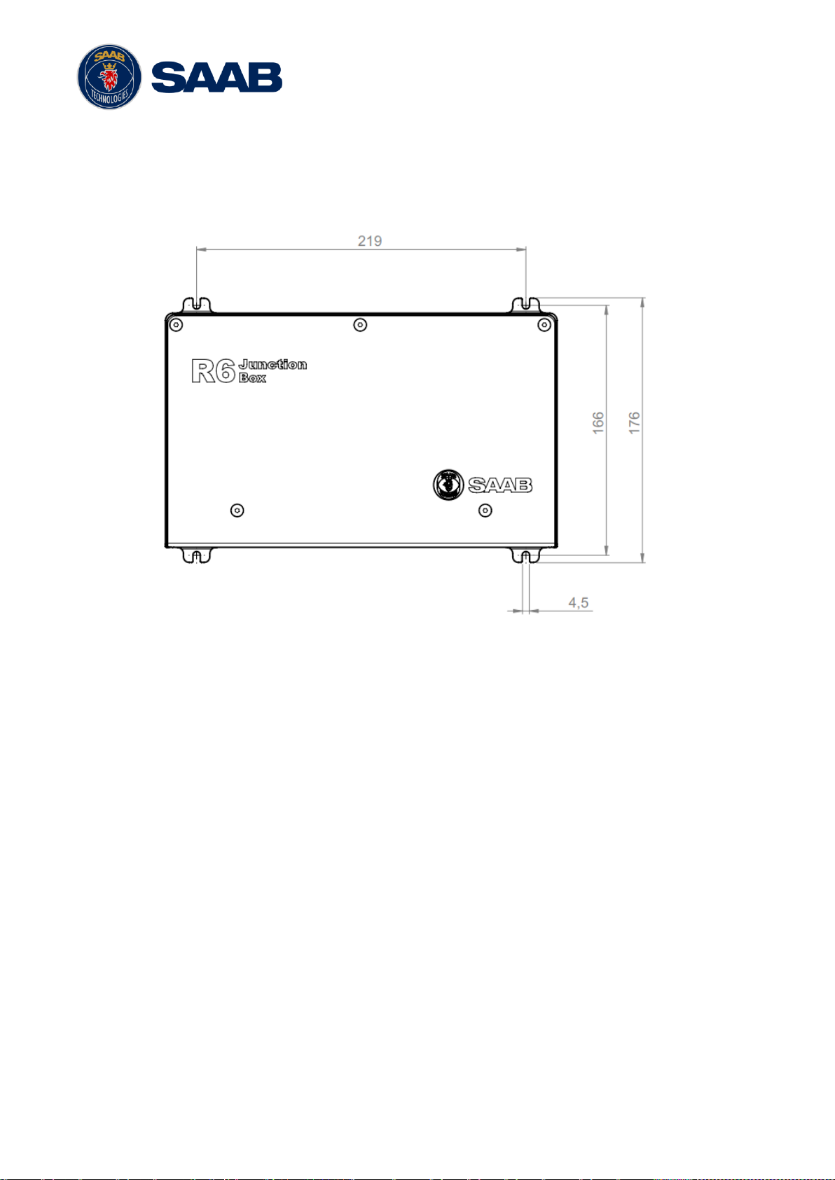
4.8.1 Junction box mounting
The unit may be wall mounter or shelf mounted. When wall mounting, it is recommended to
mount the unit with the cable opening downwards. This reduces the risk of water ingress.
Figure 4-5 –R6 Junction Box mounting dimensions
Open the lid of the R6 Junction Box.
Fix the box on an appropriate surface/place with using the screw holes on the four feet of
the junction box.
Shielded cables should be stripped down to the shielding and fastened with cable ties (not
included)
Connect the cables to the terminal blocks.
Fix the lid to the box casing.
NOTE: Cables meant for connection to the screw terminals inside the R6 Junction box have a
maximum diameter of 13mm, due to space limitations entering the box.
4.8.2 Junction Box Interfaces
The Junction box features one 26-pin DSUB connector and one 9-pin DSUB connector. All other
connectors are internal of terminal block type.
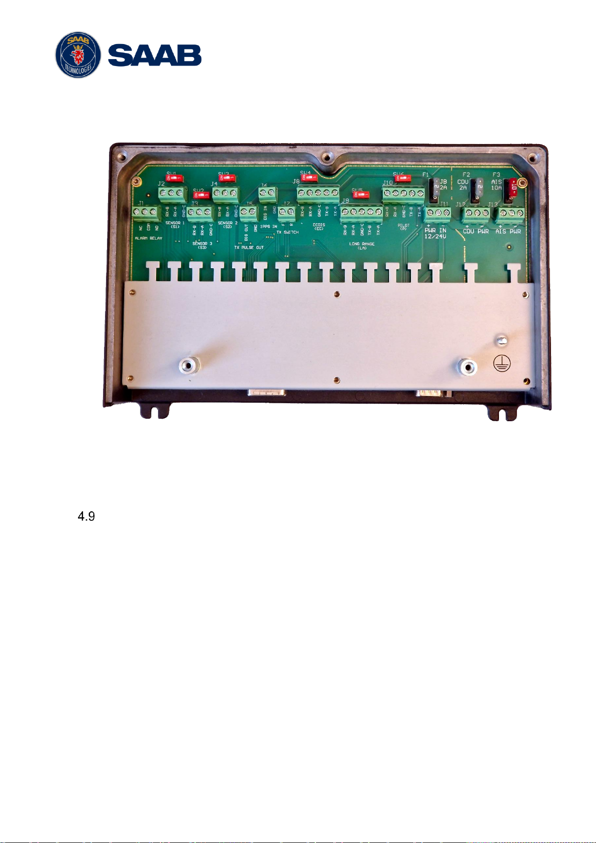
R6 SUPREME System
7000 121-304, A1 Page 22
NOTE: The R6 Junction Box has three internal fuses. F3 “AIS” fuse protects the AIS PWR output
(10A), F2 “CDU” is for the CDU PWR output (2A) and F1 “JB” is for the junction box integrated
alarm relay (2A).
Figure 4-6 –R6 Junction Box interface
Please see Section 16.3 “R6 Junction box Interfaces” for details.
Mount the VHF Antenna
The R6 SUPREME Transponder, like any other transceiver operating in the VHF maritime band,
may cause interference to a ship’s VHF radiotelephone. Because AIS is a communication system
with time slotted transmission, this interference may occur as a periodic (e.g. every 10 second) soft
clicking sound on a ship’s radiotelephone. This effect may become more noticeable when the VHF
radiotelephone antenna is located close to the AIS VHF antenna and when the radiotelephone is
operating on channels near the AIS operating channels (e.g. channels 27, 28 and 86).
Attention should be paid to the location and installation of different antennas in order to obtain the
best possible efficiency. Special attention should be paid to the installation of mandatory antennas
like the AIS antennas.
Therefore, installing the AIS VHF antenna is also a crucial part of the system installation. How and
where you install your AIS VHF antenna and cable will affect its efficiency.
4.9.1 VHF Antenna Location
Location of the mandatory AIS VHF antenna should be carefully considered. Digital
communication is more sensitive than analogue/voice communication to interference created by
reflections in obstructions like masts and booms. It may be necessary to relocate the VHF

R6 SUPREME System
7000 121-304, A1 Page 23
radiotelephone antenna to minimize the interference effects. Installing the VHF antenna for AIS
on a vessel is a compromise between the following items:
Antenna type
Antenna separation
Clear view of the horizon
Antenna height
4.9.1.1 Antenna Type
The AIS VHF antenna should have Omni directional vertical polarization providing unity gain.
4.9.1.2 Antenna Separation
AIS transponders use simplex channels at frequencies on the high side of the marine mobile
band (AIS channel A = 2087, 161.975 MHz, and AIS channel B = 2088, 162.025 MHz). These
channels are close to the duplex channels used for shore to ship marine communication. The
AIS VHF antenna should be separated as much as possible from the voice VHF installations
used for main communication to avoid unnecessary interference.
There should not be more than one antenna on the same level. The AIS VHF antenna should
be mounted directly above or below the ship’s primary VHF radiotelephone antenna, with no
horizontal separation and with a minimum of 2 meters vertical separation. If it is located on
the same level as other antennas, the distance apart should be at least 10 meters.
The AIS VHF antenna should be installed safely away from interfering high-power radiating
sources like radar and other transmitting radio antennas, preferably at least 3 meters away
from and out of the transmitting beam.
4.9.1.3 Clear View of the Horizon
The AIS VHF antenna should be placed in an elevated position that is as free as possible
with a minimum distance of 2 meters in horizontal direction from constructions made of
conductive materials. The antenna should not be installed close to any large vertical
obstruction. The objective for the AIS VHF antenna is to see the horizon freely through 360
degrees.
4.9.1.4 VHF Antenna Height
The AIS is using VHF radio frequencies, which propagation characteristics are close to line
of sight. The higher the antenna location is, the longer the range will be.
4.9.2 VHF Cabling
The cable should be kept as short as possible to minimize attenuation of the signal. Double
shielded coaxial cable equal or better than RG214 is recommended to minimize the effects from
electromagnetic interference from high power lines, radar or other radio transmitter cables.
The table below gives recommendation on cables that can be used for the VHF-antenna
connections. The cable attenuation shall be kept as low as possible; a 3 dB loss is the same as
cutting the signal strength in half.

R6 SUPREME System
7000 121-304, A1 Page 24
Example: A cable of 40 meter RG 214 has a cable attenuation of 2.8 dB.
4.9.3 VHF Cable Mounting
Coaxial cables should be installed in separate signal cable channels/tubes and at least 10 cm
away from power supply cables. Crossing of cables should be done at right angles (90°).
Coaxial cables should not be exposed to sharp bends, which may lead to a change of the
characteristic impedance of the cable. The minimum bending radius should be 5 times the
cable's diameter.
All outdoor installed connectors should be weather proofed, e.g. with shrink tubing, watertight
seal tape or butyl rubber tape and plastic tape sealing, to protect against water penetration into
the antenna cable.
Secure the cable properly close to the cable ends.
4.9.4 VHF Cable Grounding
Coaxial down-leads must be grounded. The coaxial shielding screen should be connected to
ground.
Mount the GNSS Antenna
The R6 SUPREME shall be connected to one of the approved GNSS antenna types. 5V DC is
supplied through the antenna lead for the antenna preamplifier.
If a combined GNSS/VHF antenna is used, the diplexer unit shall be installed in an indoors
environment.
Attention should be paid to the location and installation of the different antennas on the ship in
order to obtain the best possible efficiency. Special attention should be paid to the installation of
mandatory antennas like the AIS units antennas.
Therefore, installation of the GNSS antenna is a crucial part of the system installation. How and
where you install your GNSS antenna and cable will greatly affect its sensing efficiency.
4.10.1 GNSS Antenna Location
The GNSS antenna must be installed where it has a clear view of the sky. The objective is to
see the horizon freely through 360 degrees with a vertical observation of 5 to 90 degrees above
the horizon. Small diameter obstructions, such as masts and booms do not seriously degrade
signal reception, but such objects should not eclipse more than a few degrees of any given
Type
Attenuation @
150 MHz
(dB/100m)
(mm)
Weight (kg/100m)
RG 214
7
10.8
18.5
RG 217
5
13.8
30.1
RG 225
8
10.9
23.3
Table 5 – VHF Antenna Cables

R6 SUPREME System
7000 121-304, A1 Page 25
bearing. Do not mount the antenna in the top of a mast or tower, as this may degrade the COG
and SOG readings.
Locate the GNSS antenna at least 3 meters away from and out of the transmitting beam of highpower transmitters such as S-Band Radar (typically 15° vertically from the array’s centre point)
and/or Inmarsat systems (A, B, C, or M; typically 10º from the array’s centre point in any of the
possible transmitting directions).
Locate the GNSS antenna at least 3 meters away from HF or VHF radios or their antennas. This
includes the ship’s own AIS VHF antenna if it is designed and installed separately.
4.10.2 GNSS Cabling
The gain of the GNSS antenna built-in pre-amplifier shall match the cable attenuation. The
resulting installation gain (pre-amplifier gain minus cable attenuation) shall be within 0 to 26 dB.
A minimum value of 10 dB is recommended for optimum performance.
Double shielded coaxial cable is recommended. The coaxial cable should be routed directly
between the GNSS antenna and the R6 SUPREME Transponder’s GNSS connector in order to
reduce electromagnetic interference effects. The cable should not be installed close to highpower lines, such as radar or radio-transmitter lines or the AIS VHF antenna cable. A separation
of 1 meter or more is recommended to avoid interference due to RF-coupling. Crossing of
antenna cables should be done at 90 degrees to minimise magnetic field coupling.
The table below gives recommendation on cables that can be used for the Transponder GNSSantenna connections. Due to the high frequency it’s important that the attenuation in the cable
is low for the specific frequency (1.5 GHz).
Type
Attenuation @
1.5 GHz (dB/m)
(mm)
Weight (kg/100m)
RG 58
0.9 5 3.7
RG 400
0.6
4.95
6.3
RG 223
0.6
5.40
5.5
RG 214
0.35
10.8
18.5
RG 225
0.3
10.9
23.3
Table 6 – GNSS Antenna Cables
For optimum performance approximately +10dB gain should be available when the cable
attenuation has been subtracted from the GNSS-antenna preamplifier gain. The net gain shall
not exceed +26dB.

R6 SUPREME System
7000 121-304, A1 Page 26
Example:
Cable
type
Preamplifier
gain (dB)
Required min.
cable length (m)
Recommended
max. cable length
(m)
RG 58
12 0 2
RG 58
26 0 18
RG 58
30
4.5
22
RG 223
12 0 3.5
RG 223
26 0 26.5
RG 223
30
6.5
33.5
RG 214
12 0 6
RG 214
26 0 46
RG 214
30
11.5
57
Table 7 – GNSS Antenna Cable Examples
Min length = (Preamp. Gain – 26 dB)/Cable attenuation per meter.
Max length = (Preamp. Gain – 10 dB)/Cable attenuation per meter.
4.10.3 GNSS Cable Mounting
Coaxial cables should be installed in separate signal cable channels/tubes and at least 10 cm
away from power supply cables. Crossing of cables should be done at right angles (90°).
Coaxial cables should not be exposed to sharp bends, which may lead to a change of the
characteristic impedance of the cable. The minimum bending radius should be 5 times the
cable's diameter.
All outdoor installed connectors should be weather proofed, e.g. with shrink tubing, watertight
seal tape or butyl rubber tape and plastic tape sealing, to protect against water penetration into
the antenna cable.
Secure the cable properly near the cable ends.
4.10.4 GNSS Cable Grounding
Coaxial down-leads must be used. The coaxial shielding screen should be connected to ground.
Electrical Installation details
For complete specification of signal interface details see Section 16 “Electrical Interfaces”.
4.11.1 Input ports
The protocol of the serial port interfaces is compliant to IEC 61162-1 Ed.5.

R6 SUPREME System
7000 121-304, A1 Page 27
All serial ports in the R6 SUPREME Transponder have the same capabilities with one exception,
any Long Range equipment must be connected to the Long Range port. Apart from that, all ports
can be connected to any external equipment such as ECDIS and external sensors. The primary
external position sensor should be connected to the Sensor 1 port since this port has the highest
priority. The serial ports in the R6 SUPREME Transponder can also receive differential
corrections in RTCM format for the internal GNSS receiver. The ports in the R6 SUPREME
Transponder have different default baud rates but they can all be configured to any baud rate of
4800, 9600, 38400, 57600 or 115200 bps. The priority levels for input of sensor data on the
different ports are listed below:
Priority
Identification
Default Baud Rate
1
(Highest
priority)
Sensor 1
4800 bps
2
Sensor 2
4800 bps
3
Sensor 3
4800 bps
4
ECDIS
38400 bps
5
Long Range
9600 bps
6 (Lowest
priority)
Transponder Pilot
38400 bps
N/A
CDU J1 Serial port
38400 bps (fixed)
Table 8 – Port Priorities and Default Baud Rates
If valid position data from external position sources are input on both Sensor 1 and ECDIS port,
the position data from Sensor 1 will be used.
If the same data is provided using different NMEA sentences on the same port, the priority
depends on the sentence in accordance with Table 9.
Priority
Position
COG/SOG
HDG
ROT
1
(Highest)
RMC
RMC
THS
ROT
2
GNS
VTG
HDT
-
3
GGA
VBW
OSD
-
4
GLL
OSD - -
Table 9 – Sentence priority
4.11.2 Output Drive Capacity for Serial Ports
Each serial port transmitter can have a maximum of 10 listeners assuming 2.0 mA current for
each listener.
4.11.3 Input Load
Input impedance for each listener input is 6.4 kΩ.
R6 SUPREME System
7000 121-304, A1 Page 28
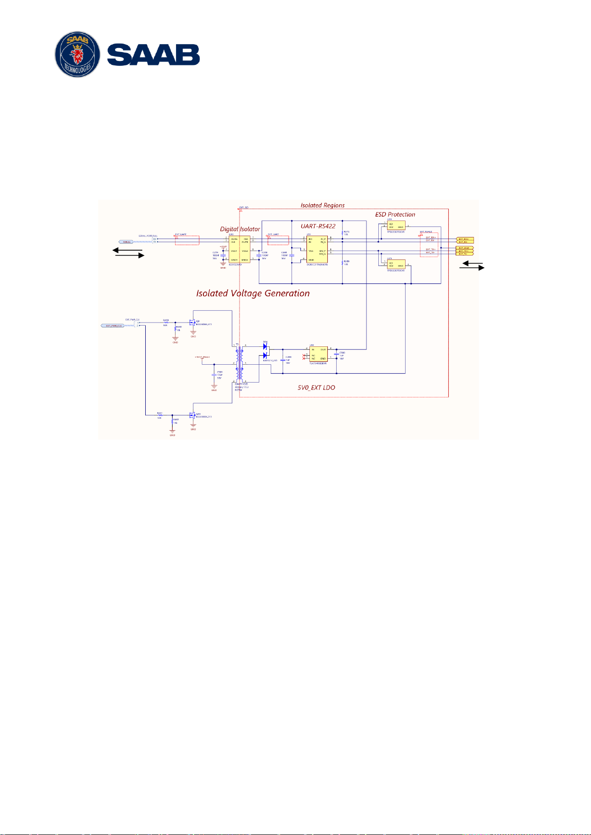
4.11.4 Schematics of Serial Transceivers
Each of the RS422 serial interfaces fulfils the requirements of IEC 61162-2 and IEC 61993-2. A
detailed schematic of one of the serial ports is shown below. R6 SUPREME input only serial
ports (Sensor 1-3) do not have the UART-RS422 TX signals connected. The CDU J1 serial
interface uses the same design as the R6 SUPREME bi-directional ports.
Internal
signals to
system
To connected
equipment
Figure 4-7 – Serial Port Schematics

R6 SUPREME System
7000 121-304, A1 Page 29
4.11.5 Transponder Connections
Connect Transponder Ground to ship ground
Install network cable according to system set up. See Section 15 System Setups
Connect Signal Cables to Junction box.
Connect GNSS antenna to GNSS port and
VHF antenna to VHF port
Connect Power Cable to Junction box.
4.11.6 CDU Electrical Connections
Connect Ethernet cable to network or directly to R6 Supreme Transponder Ethernet
port.
Connect Power Cable to Junction box or other external power with 2A Fuse.
Connect Ground terminal to ship ground.
4.11.7 R6 Junction box connections
Figure 4-1 show a general overview on how the R6 Supreme Transponder can be connected to
the R6 Junction Box. For a more detailed description of the cable connections, see Section 4.3
Installation Cables.
4.11.7.1 R6 Supreme System connections
Connect External power to the POWER IN.
Connect the Saab Power cable from R6 Supreme Transponder to AIS PWR terminal
Connect the Saab Power cable from R6 CDU to CDU PWR terminal (optional)
NOTE: R6 CDU can be mounted in a remote location and use another power source, but in this
case needs an external fuse (2A).
Connect Signal Cables from R6 Transponder J1 and J2 ports to R6 Junction box DSUB
connectors.
4.11.7.2 External Serial Sensor connections
Connect external sensor providing GNSS Position (mandatory)
Connect external sensor providing True Heading, and Rate of Turn if available.
Connect: DGPS Beacon receiver providing RTCM-104 format data to any of the RS-422
input screw terminals, if available.
Connect Pilot Plug port cable to PILOT
Connect ECDIS/RADAR to ECDIS port
NOTE: Above data may also be provided using the Ethernet interfaces, provided the external
equipment conforms to IEC 61162-450

R6 SUPREME System
7000 121-304, A1 Page 30
4.11.8 External Switch
It is possible to connect an external switch to the R6 SUPREME Transponder.
The switch may be used to quickly turn off transmissions (TX OFF), or it may also be used to
force the radio transmit power to 1W only.
NOTE: Manually set 1W mode operation, or Silent Mode, is outside of type approved operational
mode.
The status of the switch can be controlled by connecting to the R6 Junction Box (R) and (F)
signals in the “TX Switch” terminal block.
Connect the external switch as in the figure below. When the switch is open, all VHF
transmissions will be disabled or only transmit in low power mode depending on configuration.
When the switch is closed, the R6 SUPREME Transponder will transmit normally or transmit at
normal power level.
Figure 4-8 – External Switch
4.11.9 Alarm Relay
It is required that the AIS alert output (relay) is connected to an audible alert device or the ship’s
alert system, if available. The R6 AIS Junction Box has a built in alert relay that can be connected
to the ship’s alert system. If the installation is done without the junction box, an external alarm
relay should be connected.
Alternatively, the ship’s alert system may use the alert messages output on the AIS Presentation
Interface (PI) provided the alert system is AIS compatible. The AIS Alarm Relay is either
mounted on a DIN mounting rail or direct on the wall.
The alarm relay wires have the following colour codes in the 26-pole signal cable:
RELAY VCC
Brown / Red
RELAY GND
White / Pink
RELAY OUT
Pink / Brown
Table 10 – Alarm Relay Wires
Figure 4-9 – Alarm Relay
External
Switch
Ext Switch (R)
Ext Switch (F)