

S&A CW-3000 Series, CW-3000AG, CW-3000DG, CW-3000DF, CW-3000AK User Manual
...
CW-3000 USER MANUAL
1
CW-3000
INDUSTRIAL CHILLER
USER MANUAL

CW-3000 USER MANUAL
2
<1> INTRODUCTION
CW-3000 Series is professional cooling machine referring to international
advanced thermolysis cooling system design, suitable for small
water-cooled cooling devices requested machinery.
1. Specific disconnection alarm security protection.
2. Hermetic type water tank, water is available for a long time used.
3. Real-time temperature monitoring, accurate knowledge of heating devices
working condition.
4. Professional air-cooled forced radiator with strong heat dissipating
capacity and difficult to be blocked up.
5. Equipped with alarm output port to protect sensitive components quickly.
6. High cost performance, low failure rate.
7. There are several options of power supply, complete in specifications.
<2> CAUTION
1. It is strictly forbidden to plug and run the cooler without feeding water.
2. Cooler should be placed in a well-ventilated, dry environment place and
away from heat sources. Please keep at least 30cm from obstructions to the
air outlet which is in the back of the cooler, and should leave at least 10cm
between obstructions and air inlets of two sides.
3. The cooling water must be drained if the cooler is out of use for long time or
before being transported.
4. To protect laser tubes , the radiator fan of cooler will suspend to work when
water temperature is lower ( about 10℃ ) , and it will restart to run when
water temperature rises to higher ( about 20 ℃).
CW-3000 USER MANUAL
3
<3> Details
1.Shape and parts name
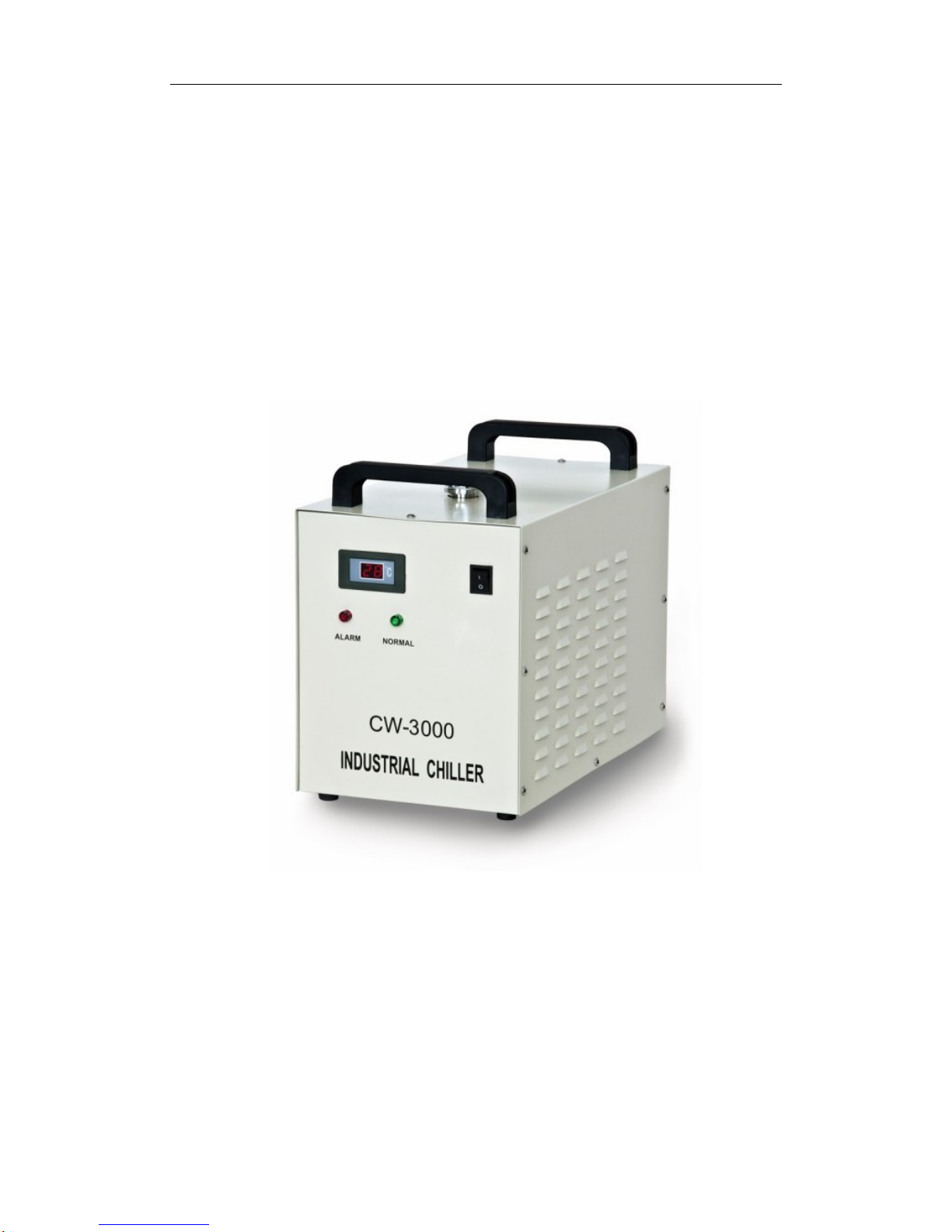
FRONT
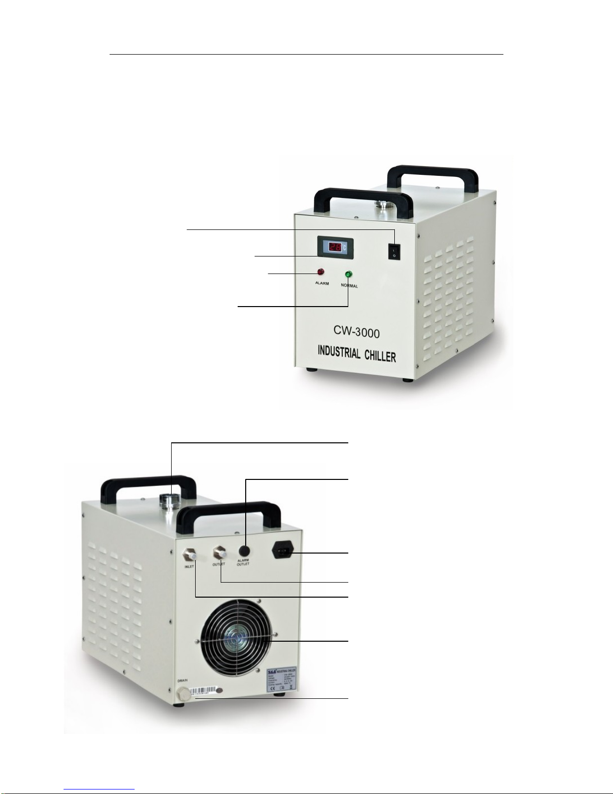
BACK
POWER SW
TEMPERATURE DISPLAY
SYSTEM ALARM INDICATOR
RUNNING INDICATOR
WATER SUPPLY INLET
ALARM SIGNAL OUTPUT TERMINAL
POWER SOCKET (WITH FUSE)
OUTLET
INLET
WATER DRAIN
RADIATOR FAN

CW-3000 USER MANUAL
4
2. The first installation
It is very simple to install this industrial cooling machine. The first time
installation of the new machine can be carried out by following steps.
1. Open the package to check if the machine is intact and all the necessary
accessories are completed.
2. Open the injection port, then add cooling water.
3. According to system conditions, connect the water inlet and outlet pipe
well.
4. Plug in power, turn on the power switch. (Do not allow the water overflow)
5. Check the w ater level of the water tank again. (It should be 80-150cm from
the surface of water to the injection port)
3. Alarm description
Causes of the cooling water circulation loop alarm and the working condition
table.
Display
Condition
Green
light
Red
light
Buzzer
out
H1、H2
out
H1、H3
Normal On Off No voice Off On
Water stops up Off On Voice On Off
Surpasses 60℃
Off On Voice On Off
Pump breakdown Off On Voice On Off
Water alarm Off On Voice On Off
Faulted circuit On Off
Power outage On Off
Note: The flow alarm port connects to the normally open relay and normally closed
relay contacts, requiring operating current to be less than 5A, working voltage less
than 300V.
 Loading...