

Page 1
XCS-165
09-16
0
10
20
30
40
50
60
70
80
90
100
110
120
130
140
150
160
170
180
0
。
45
。
50
Page 2

0
10
20
30
40
50
60
70
80
90
100
110
120
130
140
150
160
170
180
0
。
45
。
50
1
1 32
0
。
45
。
50
0
10
20
30
40
50
60
70
80
* Battery pack (18) not included
9
7
1
8
21
13
16
19
15
6
18
17
14
2
4
0
。
45
。
50
15
30
45
0
10
20
30
40
50
60
70
80
90
1
3
4
2
Loosen
Tighten
2
9
10
4
7
1
5
5
2
Page 3
2
7 8
4 65
9 10
0
。
45
。
50
100
110
120
130
140
150
160
170
180
0
10
20
30
40
50
60
70
80
90
45
0
10
30
12
13
0
30
45
50450
0
10
20
30
40
50
60
70
80
90
100
110
120
130
140
150
160
170
180
0
10
30
45
50
45
。
0
。
14
13
20
50
45
0
30
45
A
B
11
11
17
0
10
20
30
40
50
60
70
80
90
100
110
120
130
140
150
160
170
180
0
。
45
。
50
19
18
Laser beam
Page 4

THANK YOU FOR BUYING A RYOBI PRODUCT.
To ensure your safety and satisfaction, carefully read
through this OWNER’S MANUAL before using the
product.
3
General Safety Rules
SAVE THESE INSTRUCTIONS
WARNING! Read all instructions Failure to follow all instructions
listed below may result in electric shock, fire and/or serious injury.
The term “power tool” in all of the warnings listed below refers
to your mains-operated (corded) power tool or battery-operated
(cordless) power tool.
1) Work area
a) Keep work area clean and well lit. Cluttered and dark
areas invite accidents.
b) Do not operate power tools in explosive atmospheres,
such as in the presence of flammable liquids, gases or
dust. Power tools create sparks which may ignite the dust
or fumes.
c) Keep children and bystanders away while operating a
power tool. Distractions can cause you to lose control.
2) Electrical safety
a) Power tool plugs must match the outlet. Never modify
the plug in any way. Do not use any adapter plugs with
earthed (grounded) power tools. Unmodified plugs and
matching outlets will reduce risk of electric shock
b) Avoid body contact with earthed or grounded surfaces
such as pipes, radiators, ranges and refrigerators.
There is an increased risk of electric shock if your body is
earthed or grounded.
c) Do not expose power tools to rain or wet conditions.
Water entering a power tool will increase the risk of electric
shock.
d) Do not abuse the cord. Never use the cord for carrying,
pulling or unplugging the power tool. Keep cord away
from heat, oil, sharp edges or moving parts. Damaged
or entangled cords increase the risk of electric shock.
e) When operating a power tool outdoors, use an
extension cord suitable for outdoor use. Use of a cord
suitable for outdoor use reduces the risk of electric shock.
3) Personal safety
a) Stay alert, watch what you are doing and use common
sense when operating a power tool. Do not use a power
tool while you are tired or under the influence of drugs,
alcohol or medication. A moment of inattention while
operating power tools may result in serious personal injury.
b) Use safety equipment. Always wear eye rotection.
Safety equipment such as dust mask, non-skid safety
shoes, hard hat, or hearing protection used for appropriate
conditions will reduce personal injuries.
c) Avoid accidental starting. Ensure the switch is in the
off-position before plugging in. Carrying power tools
with your finger on the switch or plugging in power tools
that have the switch on invites accidents.
d) Remove any adjusting key or wrench before turning
the power
tool on. A wrench or a key left attached to a
rotating part of the power tool may result in personal injury.
e) Do not overreach. Keep proper footing and balance at
all times. This enables better control of the power tool in
unexpected situations.
f ) Dress properly. Do not wear loose clothing or jewellery.
Keep your hair, clothing and gloves away from moving
parts. Loose clothes, jewellery or long hair can be caught in
moving parts.
g) If devices are provided for the connection of dust
extraction and collection facilities, ensure these are
connected and properly used. Use of these devices can
reduce dust-related hazards.
4) Power tool use and care
a) Do not force the power tool. Use the correct power tool
for your application. The correct power tool will do the job
better and safer at the rate for which it was designed.
b) Do not use the power tool if the switch
does not turn it
on and off. Any power tool that cannot be controlled with
the switch is dangerous and must be repaired.
c) Disconnect the plug from the power source before
making any adjustments, changing accessories, or
storing power tools. Such preventive safety measures
reduce the risk of starting the power tool accidentally.
d) Store idle power tools out of the reach of children and
do not allow persons unfamiliar with the power tool or
these instructions to operate the power tool. Power
tools are dangerous in the hands of untrained users.
e) Maintain power tools. Check for misalignment or
binding of moving parts, breakage of parts and any
other condition that may affect the power tools
operation. If damaged, have the power tool repaired
before use. Many accidents are caused by poorly
maintained power tools.
f ) Keep cutting tools sharp and clean. Properly maintained
cutting tools with sharp cutting edges are less likely to bind
and are easier to control.
g) Use the power tool, accessories and tool bits etc.,
in
accordance with these instructions and in the manner
intended for the particular type of power tool, taking
into account the working conditions and the work to be
performed. Use of the power tool for operations different
from intended could result in a hazardous situation.
5) Battery tool use and care
a) Ensure the switch is in the off position before inserting
battery pack. Inserting the battery pack into power tools
that have the switch on invites accidents.
b) Recharge only with the charger specified by the
manufacturer. A charger that is suitable for one type of
battery pack may create a risk of fire when used with
another battery pack.
c) Use power tools only with specifically designated
battery packs. Use of any other battery packs may
create a risk of injury and fire.
d) When battery pack is not in use, keep it away from
other metal objects like paper clips, keys, nails, screws,
or other metal objects that can make a connection from
one terminal to another. Shorting the battery terminals
together may cause burns or a fire.
e) Under abusive conditions, liquid may be ejected from
the battery; avoid contact. If contact accidentally
occurs, flush with water. If liquid contacts eyes,
additionally seek medical help. Liquid ejected from the
battery may cause irritation or burns.
5) Service
a) Have your power tool serviced by a qualified repair
person using only identical replacement parts. This will
ensure that the safety of the power tool is maintained.
(PJ27)
Page 5

4
1. Make sure that the tool is only connected to the voltage
marked on the name plate.
2. Never use the tool if its cover or any bolts are missing. If
the cover or bolts have been removed, replace them
prior to use.
Maintain all parts in good working order.
3. Always secure the tool when working in elevated
positions.
4. Never touch the blade, drill bit, grinding wheel or other
moving parts during use.
5. Never start the tool when its rotating component is in
contact with the work piece.
6. Never lay the tool down before its moving parts have
come to a complete stop.
7. ACCESSORIES: The use of accessories or attachments
other than those recommended in this manual might
present a hazard.
8. REPLACEMENT PARTS: When servicing use only
identical replacement parts.
INSTRUCTIONS FOR SAFE HANDLING
a) Keep hands away from cutting area and the blade.
Keep your second hand on auxiliary handle, or motor
housing. If both hands are holding the saw, they cannot
be cut by the blade.
b) Do not reach underneath the workpiece. The guard
cannot protect you from the blade below the workpiece.
c) Adjust the cutting depth to the thickness of the
workpiece. Less than a full tooth of the blade teeth
should be visible below the workpiece.
d) Never hold piece being cut in your hands or across
your leg. Secure the workpiece to a stable platform.
It is important to support the work properly to minimize
body exposure, blade binding, or loss of control.
e) Hold power tool by insulated gripping surfaces when
performing an operation where the cutting tool may
contact hidden wiring or its own cord. Contact with
a "live" wire will also make exposed metal parts of the
power tool "live" and shock the operator.
f) When ripping always use a rip fence or straight edge
guide. This improves the accuracy of cut and reduces
the chance of blade binding.
g) Always use blades with correct size and shape
(diamond versus round) of arbour holes. Blades that
do not match the mounting hardware of the saw will run
eccentrically, causing loss of control.
h) Never use damaged or incorrect blade washers or
bolt. The blade washers and bolt were specially designed
for your saw, for optimum performance and safety of
operation.
i) Check lower guard for proper closing before each use.
Do not operate the saw if lower guard does not move
freely and close instantly. Never clamp or tie the lower
guard into the open position. If saw is accidentally
dropped, lower guard may be bent. Raise the lower guard
with the lower guard lever and make sure it moves freely
and does not touch the blade or any other part, in all
angles and depths of cut.
j) Check the operation of the lower guard spring. If the
guard and the spring are not operating properly, they
must be serviced before use. Lower guard may operate
sluggishly due to damaged parts, gummy deposits, or a
build-up of debris.
k) Lower guard should be retracted manually only for
special cuts such as "plunge cuts" and "compound
cuts." Raise lower guard by lower guard lever and as
soon as blade enters the material, the lower guard
must be released. For all other sawing, the lower guard
should operate automatically.
l) Always observe that the lower guard is covering the
blade before placing saw down on bench or floor. An
unprotected, coasting blade will cause the saw to walk
backwards, cutting whatever is in its path. Be aware of the
time it takes for the blade to stop after switch is released.
− kickback is a sudden reaction to a pinched, bound or
misaligned saw blade, causing an uncontrolled saw to lift
up and out of the workpiece toward the operator;
− when the blade is pinched or bound tightly by the kerf
closing down, the blade stalls and the motor reaction drives
the unit rapidly back toward the operator;
− if the blade becomes twisted or misaligned in the cut, the
teeth at the back edge of the blade can dig into the top
surface of the wood causing the blade to climb out of the
kerf and jump back toward the operator.
Kickback is the result of saw misuse and/or incorrect
operating procedures or conditions and can be avoided by
taking proper precautions as given below.
a) Maintain a firm grip with both hands on the saw and
position your arms to resist kickback forces. Position
your body to either side of the blade, but not in line
with the blade. Kickback could cause the saw to jump
backwards, but kickback forces can be controlled by the
operator, if proper precautions are taken.
b) When blade is binding, or when interrupting a cut for
any reason, release the trigger and hold the saw
motionless in the material until the blade comes to a
complete stop. Never attempt to remove the saw from
the work or pull the saw backward while the blade is
in motion or kickback may occur. Investigate and take
corrective actions to eliminate the cause of blade binding.
c) When restarting a saw in the workpiece, centre the
saw blade in the kerf and check that saw teeth are not
engaged into the material. If saw blade is binding, it may
walk up or kickback from the workpiece as the saw is
restarted.
d) Support large panels to minimise the risk of blade
pinching and kickback. Large panels tend to sag under
their own weight. Supports must be placed under the
panel on both sides, near the line of cut and near the
edge of the panel.
e) Do not use dull or damaged blades. Unsharpened or
improperly set blades produce narrow kerf causing
excessive friction, blade binding and kickback.
f) Blade depth and bevel adjusting locking levers must
be tight and secure before making cut. If blade
adjustment shifts while cutting, it may cause binding and
kickback.
g) Use extra caution when making a "plunge cut" into
existing walls or other blind areas. The protruding
blade may cut objects that can cause kickback.
CIRCULAR SAW SAFETY PRECAUTIONS
DANGER!
Causes and operator prevention of kickback:
Page 6

2. Hex. head bolt
4. Outside flange
6. Lower guard
8. Safety guard
10. Inside flange
12. Depth adjustment knob
14. Angle adjustment knob
16. Safety lock button
18. Battery pack (Not included)
20. Laser guide
1. Lock lever
3. Wrench
5. Washer
7. Lower guard lever
9. Saw Blade
11. Cutting line
13. Base plate
15. Trigger
17. Saw guide fence
19. Battery clip
21. Laser on/off button
Li-ion batteries must be recycled.
Take the battery to the shop from which it was purchased as
soon as the post-charging battery life becomes too short for
practical use.
Do not discard the exhausted battery.
DESCRIPTION
DISPOSAL OF THE EXHAUSTED BATTERY
Wrench, Saw guide fence
STANDARD ACCESSORIES
APPLICATIONS
Blade diameter ....................................................... 165mm
(Only blades of this diameter may be used.)
Blade bore diameter ................................................ 20mm
Max. cutting capacities
at 90° ....................................................... 52mm
at 45° ....................................................... 36mm
Motor ..................................................................... DC 18V
No load speed ................................................... 4,000min
-1
Net weight (not incl. battery pack) ....…….…..........…2.4kg
SPECIFICATIONS
COMPATIBLE BATTERY PACK AND CHARGER
REMOVING
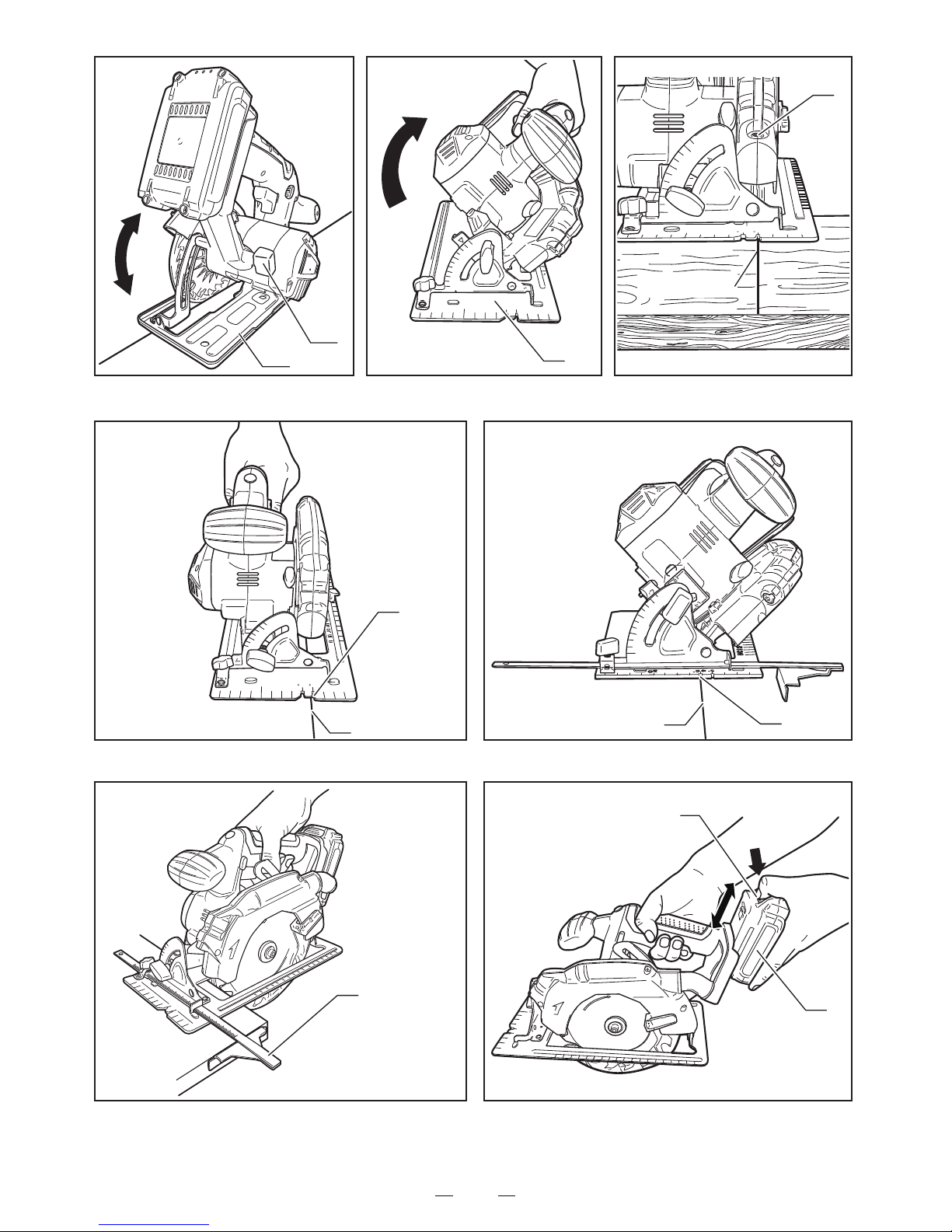
ADJUSTING THE CUTTING DEPTH (Fig. 4 )
(Use only for the purposes listed below.)
1. Sawing wood.
(The mark on the blade should be visible from the outside.)
1. Pushing the lock lever, turn the hex. head bolt with the
wrench until the gear shaft locks.
2. Loosen the hex. head bolt by turning the wrench
counterclockwise while pushing the lock lever.
3. Remove the hex. head bolt, washer and the outside flange.
4. Retract the lower guard back as far as possible toward
the safety guard, then remove the saw blade.
1. To adjust the cutting depth, loosen the depth adjustment
knob (12).
2. Slide the base plate (13) to the desired depth and
retighten the nut securely.
3. The cutting depth can be determined by measuring the
distance between the blade protrusion and the base plate.
ADJUSTING THE CUTTING BEVEL (Fig. 5)
1. The true cutting angle may be adjusted to any desired
angle between 0° and 45°.
2. Loosen the angle adjustment knob (14) which are positioned
at the front of the tool and move the base plate (13) to the
desired angle according to the bevel scale.
3. After adjusting the desired angle, be sure to retighten the
angle adjustment lever firmly.
Press the laser on/off button (21), the laser guide (20) generates
a red laser beam on the work surface in front of the saw.
Use the laser to guide the saw along the line of cut.
LASER GUIDE (Fig. 6)
SWITCH
This device is equipped with a safety switch. The device will
not switch on unless the safety lock button (16) is depressed.
To switch the device on press and hold the safety lock button
(16) then pull the trigger (15), releasing the trigger will switch
it off. If your finger is released from the switch, the safety lock
button will automatically return to the center position,
preventing the device from being switched on.
WARNING!
Instructions not to use any abrasive wheels.
ATTACHING
2. Loosen the hex. head bolt by turning the wrench
counterclockwise while pushing the lock lever. (Fig. 1)
3. Remove the hex. head bolt, washer (5) and the outside flange (4).
4. Retract the lower guard (6) back with the lower guard
lever (7) as far as possible toward the safety guard (8). (Fig. 3)
5. Then, attach the saw blade (9) against the flange (10) on
the gear shaft and then the outside flange and the hex.
head bolt. (Figs. 2 and 3)
6. Push the lock lever again, tighten the hex. head bolt by
turning the wrench clockwise while pushing the lock lever.
7. After tightening the hex. head bolt, release the lock lever.
BATTERY PACK (not included) ...... XB-1500, XB-3000
CHARGER (not included) ............... XPP-2700
ASSEMBLY INSTRUCTIONS
BE SURE TO DISCONNECT THE TOOL FROM THE
POWERSUPPLY BEFORE ATTACHING AND REMOVING
THE SAW BLADE.
BE SURE THAT THE TEETH OF THE SAW BLADE ARE
POINTING UPWARD AT THE FRONT OF THE TOOL.
ATTACHING AND REMOVING THE BLADE ( Figs. 1, 2 and 3 )
5
1. Pushing the lock lever (1), turn the hex. head bolt (2) with
the wrench (3) until the gear shaft locks. (Fig. 1)
If unexpected machine cut off happens during the
operation, press the button (21) TWICE to activate
the laser guide (20) again.
NOTE:
Page 7

6
It is important to saw with steady and even pressure (DO
NOT FORCE) in order to obtain a uniform cut. Cut at a
speed suited to the work piece. (Work slowly when work
piece is hard.)
Inspect the saw blade frequently and replace or sharpen if
dull, to avoid overloading the motor.
・During use, do not point the laser beam at people, directly
or indirectly through reflecting surfaces.
・This laser was classified as class 2 according to EN
60825-1:2007. The unit includes no servicing components.
Do not open the housing for any reason. If the unit is
damaged, have the damage repaired by an authorized
repair agent.
WARNING! The laser beam potentially causes severe eye
damage. Never look or stare directly into the laser beam.
STORING THE TOOL
places which can be reached by children or from where the
tool may fall.
Pay attention to the following when storing the battery pack
for an extended period of time.
a. Store lithium ion batteries when they are charged.
b. Avoid high temperatures. Do not store for an extended
period of time in places that are 45°C or hotter.
c. Do not store in places that are -20°C or colder.
d. Do not store in places that are near to heat sources or
places that are subject to direct sunlight.
e. Do not store in places which have large changes in
temperature and may have condensation.
f. Do not store in humid places.
g. Do not allow it come in contact with water.
h. Store in a dry place.
i. Do not subject it to large vibrations or allow it to fall when
moving it.
j. In order to avoid short circuits, do not allow it come in
contact with metal objects.
k. Before storing the battery pack, remove it from the
charger.
CUTTING POSITION (Figs. 7 and 8)
Cutting the work piece at 90°, use point “A” of the base plate
line guide and move the saw along the penciled line to be cut.
Cutting at 45°, use point “B”.
This line guide shows an approximate line of cut.
Make a sample cut in scrap lumber to verify the actual line of
cut.
USE OF SAW GUIDE FENCE (Fig. 9)
Use of the saw guide fence (17) eliminates the necessity of
drawing guide lines on the work piece.
Particularly useful when making many pieces of the same
size.
CHARGING BATTERY PACK
Read and follow all warnings and instructions in owner’s
manual of the XPP-2700.
The cutting width can be easily established by setting the
guide fence at the desired distance from the blade.
The saw guide fence can be attached on either the right or
left side of the base plate.
The saw guide fence should only touch the work piece
slightly and should not be forced.
OPERATING
DANGER!
CAUTION!
KEEP HANDS AWAY FROM THE CUTTING AREA. WHEN
OPERATING THE TOOL, KEEP THE CORD AWAY FROM
THE CUTTING AREA AND POSITION IT SO THAT IT WILL
NOT BE CAUGHT ON THE WORK PIECE DURING THE
CUTTING OPERATION.
INSTALLING AND REMOVING BATTERY PACK
(Fig. 10)
MAINTENANCE
To ensure safety and reliability, all repairs should be
performed by an AUTHORIZED SERVICE CENTER or
other QUALIFIED SERVICE ORGANIZATION.
“ WARNING! To reduce the risk of injury, user must read
instruction manual ”
SAVE THESE INSTRUCTIONS FOR FUTURE REFERENCE.
WARNING!
After use, check the tool to make sure that it is in top
condition. It is recommended that you take this tool to a
RYOBI Authorized Service Center for a thorough cleaning
and lubrication at least once a year.
DO NOT MAKE ANY ADJUSTMENTS WHILE THE
MOTOR IS IN MOTION.
ALWAYS DISCONNECT THE POWER CORD FROM THE
RECEPTACLE BEFORE CHANGING REMOVABLE OR
EXPENDABLE PARTS (BLADE, BIT, SANDING PAPER
ETC.), LUBRICATING OR WORKING ON THE UNIT.
To install battery pack, lock the trigger switch by placing the
forward/reverse switch in the center position. Align the body
with the groove in the battery pack and push in the direction
of the arrow until the battery pack (18) is secured on the tool.
To remove the battery pack from the tool, push the push
button (19) on and remove the battery pack in the direction
of the arrow.
Always remove battery pack from your tool when you are
assembling parts, making adjustments, cleaning, or when
not in use. Removing battery pack will prevent accidental
starting that could cause serious personal injury.
Page 8

RYOBI POWER EQUIPMENT
WARRANTY
Subject to the warranty conditions below, this
RYOBI tool (hereinafter called “the Product”),
is warranted by Ryobi (herein called “the
Company”) to be free from defects in material
or workmanship for a period of 24 months
from the date of original purchase covering
both parts and labour. Under the terms of
this warranty, the repair or replacement of
any part shall be the opinion of the Company
or its authorised agent. Should service
become necessary during the warranty
period, the owner should contact the
authorised Ryobi retailer from whom the
product was purchased, or the nearest
Company branch of
fice. In order to obtain
warranty service, the owner must include the
Sales Docket and Warranty Certificate to
confirm date of purchase. This Product is
sold by the dealer or agent as principal and
the dealer has no authority from the Company
to give any additional warranty or guarantee
on the Company’s behalf except as herein
contained or herein referred to.
Warranty Conditions
This warranty only applies provided that the
Product has been used in accordance with
the manufacturer's recommendations under
normal use and reasonable care (in the
opinion of the Company) and such warranty
does not cover consumable components,
damage, malfunction or failure resulting from
misuse, neglect, abuse
, or used for a purpose
for which it was not designed, or is not suited
and no repairs, alterations or modifications
have been attempted by other than an
Authorised Service Agent. This guarantee
will not apply if the tool is damaged by
accident or if repairs arise from normal wear
and tear.
Accessories such as bits,blades, sanding
discs, cutting lines, etc., are excluded from
this guarantee. Normal consumable parts,
such as carbon brushes, bearings, chucks,
cord assembly’s, spark plugs, recoil pulleys
and bump head assembly’s are specifically
excluded from this guarantee.
The Company accepts no additional liability
pursuant to this warranty for the costs of
traveling or transportation of the Prod
uct or
parts to and from the sevice dealer or agent
- which costs are not included in the warranty.
Nothing herein shall have the effect of
excluding,
restricting or modifying any
conditions, warranty, right or liability imposed,
to the extent only that such exclusion,
restriction or modification would render any
term herein void.
THIS WARRANTY FORM
SHOULD BE RETAINED BY THE CUSTOMER AT ALL TIMES.
For your record and to assist in establishing date of purchase (necessary for in-warranty service), please
keep your purchase docket and this form, completed with the following particulars.
PURCHASED FROM:.........................................................................................................
ADDRESS OF DEALER:....................................................................................................
DATE:......................... MODEL NO................................ SERIAL NO.................................
Present this form with your Purchase Docket when Warranty Service is required.
STEVENS & CO (Pty) Ltd
604, 16th Street, Randjespark
Midrand, South Africa
Tel: +27 (11) 357-9600
Fax: +27 (11) 805-5541
email: stevens@ryobi.co.za
P O Box 4059
HALFWAY HOUSE
1685, South Africa
 Loading...