

Page 1
OPERATOR’S MANUAL
MANUEL D’UTILISATION
MANUAL DEL OPERADOR
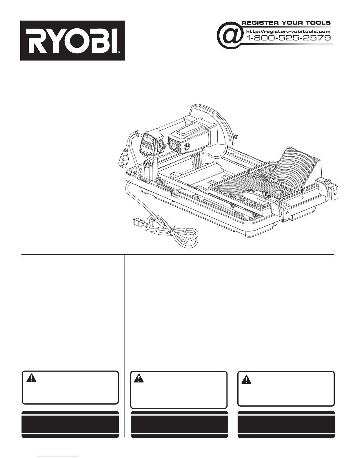
7 in. TILE SAW
SCIE À CARREAUX
DE 178 mm (7 po)
SIERRA DE LOSAS
DE 178 mm (7 pulg.)
WS731
TABLE OF CONTENTS
General Safety Rules .......................2-3
Specific Safety Rules .........................4
Symbols ..............................................5
Electrical ..........................................6-7
Features .............................................. 7
Assembly .......................................8-10
Operation .....................................10-12
Adjustments .....................................13
Maintenance ..................................... 14
Accessories ...................................... 15
Illustrations ..................................16-23
Parts Ordering
and Service .........................Back page
WARNING: To reduce the
risk of injury, the user must read and
understand the operator’s manual
before using this product.
SAVE THIS MANUAL FOR
FUTURE REFERENCE
TABLE DES MATIÈRES
Règles de sécurité générales ............2-3
Règles de sécurité particulières ...........4
Symboles ..............................................5
Caractéristiques électriques ..............6-7
Caractéristiques ................................7-8
Assemblage .....................................8-10
Utilisation .......................................10-13
Réglages ............................................. 14
Entretien ........................................14-15
Accessoires ........................................ 15
Illustrations ....................................16-23
Commande de pièces
et dépannage ......................Page arrière
AVERTISSEMENT :
Pour réduire les risques de blessures,
l’utilisateur doit lire et veiller à bien
comprendre le manuel d’utilisation avant
d’employer ce produit.
CONSERVER CE MANUEL
POUR FUTURE RÉFÉRENCE
ÍNDICE DE CONTENIDO
Reglas de seguridad generales .......2-3
Reglas de seguridad específicas .......4
Símbolos ............................................5
Aspectos eléctricos .........................6-7
Características ................................7-8
Armado ..........................................8-10
Funcionamiento ...........................10-13
Ajustes .............................................. 14
Mantenimiento .............................14-15
Accesorios ........................................ 15
Illustraciones ...............................16-23
Pedidos de piezas
y servicio ....................... Pág. posterior
ADVERTENCIA: Para reducir
el riesgo de lesiones, el usuario debe
leer y comprender el manual del
operador antes de usar este producto.
GUARDE ESTE MANUAL
PARA FUTURAS CONSULTAS
Page 2

GENERAL SAFETY RULES
WARNING:
Read and understand all instructions. Failure to follow
all instructions listed below, may result in electric shock,
fire and/or serious personal injury.
READ ALL INSTRUCTIONS
KNOW YOUR POWER TOOL. Read the operator’s
manual carefully. Learn the saw’s applications and
limitations as well as the specific potential hazards related
to this tool.
GUARD AGAINST ELECTRICAL SHOCK BY PREVENT-
ING BODY CONTACT WITH GROUNDED SURFACES.
For example, pipes, radiators, ranges, refrigerator enclosures.
KEEP GUARDS IN PLACE and in good working order.
REMOVE ADJUSTING KEYS AND WRENCHES. Form
habit of checking to see that keys and adjusting wrenches
are removed from tool before turning it on.
KEEP WORK AREA CLEAN. Cluttered areas and benches
invite accidents. DO NOT leave tools or pieces of tile on
the saw while it is in operation.
DO NOT USE IN DANGEROUS ENVIRONMENTS. Do
not use power tools in damp or wet locations or expose
to rain. Keep the work area well lit.
KEEP CHILDREN AND VISITORS AWAY. All visi-
tors should wear safety glasses and be kept a safe
distance from work area. Do not let visitors contact
tool or extension cord while operating.
MAKE WORKSHOP CHILDPROOF with padlocks and
master switches, or by removing starter keys.
DON’T FORCE TOOL. It will do the job better and safer
at the feed rate for which it was designed.
USE RIGHT TOOL. Don’t force the tool or attachment to
do a job it was not designed for. Don’t use it for a purpose
not intended.
USE THE PROPER EXTENSION CORD. Make sure your
extension cord is in good condition. Use only a cord heavy
enough to carry the current your product will draw. An
undersized cord will cause a drop in line voltage resulting in loss of power and overheating. A wire gauge size
(A.W.G.) of at least 14 is recommended for an extension
cord 25 feet or less in length. If in doubt, use the next
heavier gauge. The smaller the gauge number, the heavier
the cord.
DRESS PROPERLY. Do not wear loose clothing, gloves,
neckties, or jewelry. They can get caught and draw you
into moving parts. Rubber gloves and nonskid footwear
(rubber soled boots) are recommended when working
outdoors. Also wear protective hair covering to contain
long hair.
ALWAYS WEAR SAFETY GLASSES WITH SIDE
SHIELDS. Everyday eyeglasses have only impact-
resistant lenses, they are NOT safety glasses.
SECURE WORK. Use clamps or a vise to hold work
when practical, it is safer than using your hand and frees
both hands to operate the tool.
DON’T OVERREACH. Keep proper footing and
balance at all times.
MAINTAIN TOOLS WITH CARE. Keep tools sharp
and clean for better and safer performance. Follow instructions for lubricating and changing accessories.
DISCONNECT TOOLS. When not in use, before
servicing, or when changing attachments, wheels, bits,
cutters, etc., all tools should be disconnected.
AVOID ACCIDENTAL STARTING. Be sure switch is off
when plugging in any tool.
USE RECOMMENDED ACCESSORIES. Consult the
operator’s manual for recommended accessories. The
use of improper accessories may risk injury.
NEVER STAND ON TOOL. Serious injury could occur if
the tool is tipped or if the cutting tool is unintentionally
contacted.
CHECK DAMAGED PARTS. Before further use of the
tool, a guard or other part that is damaged should be
carefully checked to determine that it will operate properly
and perform its intended function. Check for alignment
of moving parts, binding of moving parts, breakage of
parts, mounting and any other conditions that may affect
its operation. A guard or other part that is damaged must
be properly repaired or replaced by an authorized service
center to avoid risk of personal injury.
USE THE RIGHT DIRECTION OF FEED. Feed work into
a wheel or cutter against the direction of rotation of wheel
or cutter only.
NEVER LEAVE TOOL RUNNING UNATTENDED. TURN
THE POWER OFF. Don’t leave tool until it comes to a
complete stop.
PROTECT YOUR LUNGS. Wear a face or dust mask if
the cutting operation is dusty.
PROTECT YOUR HEARING. Wear hearing protection
during extended periods of operation.
DO NOT ABUSE CORD. Never yank cord to disconnect
from receptacle. Keep cord away from heat, oil, and sharp
edges.
ALWAYS USE AN OUTDOOR EXTENSION CORD
MARKED “W-A” OR “W”. These cords are rated for
outdoor use and reduce the risk of electric shock.
ALWAYS KEEP THE WHEEL GUARD IN PLACE and in
working order.
2 — English
Page 3

GENERAL SAFETY RULES
KEEP HANDS AWAY FROM CUTTING AREA. Keep
hands away from wheels. Do not reach underneathwork
or around or over the wheel while wheel is rotating. Do not
attempt to remove cut material when wheel is moving.
WHEEL COASTS AFTER BEING TURNED OFF.
NEVER USE IN AN EXPLOSIVE ATMOSPHERE.
Normal sparking of the motor could ignite fumes.
INSPECT TOOL CORDS PERIODICALLY. If dam-
aged, have repaired by a qualified service technician at
an authorized service facility. The conductor with insulation
having an outer surface that is green with or without yellow
stripes is the equipment-grounding conductor. If repair
or replacement of the electric cord or plug is necessary,
do not connect the equipment-grounding conductor to a
live terminal. Repair or replace a damaged or worn cord
immediately. Stay constantly aware of cord location and
keep it well away from the rotating wheel.
INSPECT EXTENSION CORDS PERIODICALLY and
replace if damaged.
GROUND ALL TOOLS. If tool is equipped with three-
prong plug, it should be plugged into a three-hole electrical receptacle.
CHECK WITH A QUALIFIED ELECTRICIAN or service
personnel if the grounding instructions are not completely
understood or if in doubt as to whether the tool is properly
grounded.
USE ONLY CORRECT ELECTRICAL DEVICES: 3-wire
extension cords that have 3-prong grounding plugs and
3-pole receptacles that accept the tool’s plug.
DO NOT MODIFY the plug provided. If it will not fit the
outlet, have the proper outlet installed by a qualified
electrician.
KEEP TOOL DRY, CLEAN, AND FREE FROM OIL AND
GREASE. Always use a clean cloth when cleaning. Never
use brake fluids, gasoline, petroleum-based products, or
any solvents to clean tool.
STAY ALERT AND EXERCISE CONTROL. Watch what
you are doing and use common sense. Do not operate
tool when you are tired. Do not rush.
DO NOT USE TOOL IF SWITCH DOES NOT TURN IT
ON AND OFF. Have defective switches replaced by an
authorized service center.
USE ONLY CORRECT WHEELS. Do not use wheels with
incorrect size holes. Never use washers or arbor nuts that
are defective or incorrect. The maximum wheel capacity
of your saw is 7 in. (178 mm).
BEFORE MAKING A CUT, BE SURE ALL ADJUST-
MENTS ARE SECURE.
NEVER TOUCH WHEEL or other moving parts during
use.
NEVER START A TOOL WHEN ANY ROTATING COM-
PONENT IS IN CONTACT WITH THE WORKPIECE.
DO NOT OPERATE A TOOL WHILE UNDER THE
INFLUENCE OF DRUGS, ALCOHOL, OR ANY
MEDICATION.
WHEN SERVICING use only identical replacement parts.
Use of any other parts may create a hazard or cause
product damage.
USE ONLY RECOMMENDED ACCESSORIES listed in
this manual or addendums. Use of accessories that are
not listed may cause the risk of personal injury. Instructions for safe use of accessories are included with the
accessory.
DOUBLE CHECK ALL SETUPS. Make sure wheel is tight
and not making contact with saw or workpiece before
connecting to power supply.
3 — English
Page 4
SPECIFIC SAFETY RULES
ALWAYS SECURE WORK firmly against the rip guide or
bevel block.
NEVER stand or have any part of your body in line with
the path of the wheel.
NEVER attempt to free a stalled wheel without first turning
the saw OFF and disconnecting the saw from the power
source.
IF THE POWER SUPPLY CORD IS DAMAGED, it must
be replaced only by the manufacturer or by an authorized
service center to avoid risk.
AVOID AWKWARD OPERATIONS AND HAND
POSITIONS where a sudden slip could cause your hand
to move into the cutting tool.
MAKE SURE THE WORK AREA HAS AMPLE LIGHTING
to see the work and that no obstructions will interfere with
safe operation BEFORE performing any work using the
saw.
ALWAYS TURN OFF SAW before disconnecting it, to
avoid accidental starting when reconnecting to power
supply.
THIS TOOL should have the following markings:
a) To reduce the risk of injury, the user must read and
understand operator’s manual.
b) Wear eye, hearing, and respiratory protection when
operating the tool.
c) Do not remove the wheel guard.
d) Never operate the tool without the wheel guard se-
curely closed.
e) Turn off tool, wait for the wheel to stop moving and
disconnect the power to the tool before servicing,
when changing cutting wheels, or cleaning.
f) Never use wheels that have openings, grooves, or
teeth on this tool.
g) Always inspect and replace damaged cutting wheels
before operating the tool.
h) Do not expose to rain or other damp locations.
i) Do not fill water bath above maximum water fill line.
SAVE THESE INSTRUCTIONS. Refer to them
frequently and use to instruct other users. If you loan
someone this tool, loan them these instructions too.
CALIFORNIA PROPOSITION 65
WARNING:
This product and some dust created by power sanding, sawing, grinding, drilling, and other construction activities may
contain chemicals, including lead, known to the State of California to cause cancer, birth defects, or other reproductive
harm. Wash hands after handling.
Some examples of these chemicals are:
• lead from lead-based paints,
• crystalline silica from bricks and cement and other masonry products and,
• arsenic and chromium from chemically treated lumber.
Your risk from exposure to these chemicals varies, depending on how often you do this type of work. To reduce your
exposure, work in a well-ventilated area and with approved safety equipment, such as dust masks that are specially
designed to filter out microscopic particles.
4 — English
Page 5
SYMBOLS
The following signal words and meanings are intended to explain the levels of risk associated with this product.
SYMBOL SIGNAL MEANING
DANGER:
WARNING:
CAUTION:
NOTICE:
Some of the following symbols may be used on this product. Please study them and learn their meaning. Proper
interpretation of these symbols will allow you to operate the product better and safer.
Indicates an imminently hazardous situation, which, if not avoided, will result
in death or serious injury.
Indicates a potentially hazardous situation, which, if not avoided, could result
in death or serious injury.
Indicates a potentially hazardous situation, which, if not avoided, may result in
minor or moderate injury.
(Without Safety Alert Symbol) Indicates a situation that may result in property
damage.
SYMBOL NAME DESIGNATION/EXPLANATION
Safety Alert Indicates a potential personal injury hazard.
Read Operator’s Manual
Eye, Ear, & Breathing
Protection
To reduce the risk of injury, user must read and understand operator’s manual before using this product.
Always wear eye protection with side shields marked to comply
with ANSI Z87.1 along with hearing and breathing protection.
Wet Conditions Alert Do not expose to rain or use in damp locations.
No Hands Symbol
Electrocution Failure to properly ground can result in electrocution.
V Volts Voltage
A Amperes Current
Hz Hertz Frequency (cycles per second)
min Minutes Time
Alternating Current Type of current
n
o
No Load Speed Rotational speed, at no load
Failure to keep your hands away from the wheel will result in
serious personal injury.
.../min Per Minute Revolutions, strokes, surface speed, orbits etc., per minute
5 — English
Page 6
ELECTRICAL
EXTENSION CORDS
Use only 3-wire extension cords that have 3-prong grounding plugs and 3-pole receptacles that accept the tool’s plug.
When using a power tool at a considerable distance from
the power source, use an extension cord heavy enough
to carry the current that the tool will draw. An undersized
extension cord will cause a drop in line voltage, resulting in
a loss of power and causing the motor to overheat. Use the
chart provided below to determine the minimum wire size
required in an extension cord. Only round jacketed cords
listed by Underwriter’s Laboratories (UL) should be used.
**Ampere rating (on tool data plate)
0-2.0 2.1-3.4 3.5-5.0 5.1-7.0 7.1-12.0 12.1-16.0
Cord Length Wire Size (A.W.G.)
25' 16 16 16 16 14 14
50' 16 16 16 14 14 12
100' 16 16 14 12 10 —
**Used on 12 gauge - 20 amp circuit.
NOTE: AWG = American Wire Gauge
Always use an extension cord that is designed for outside
use. This is indicated by the letters “W-A” or “W” on the
cord’s jacket.
Before using an extension cord, inspect it for loose or
exposed wires and cut or worn insulation.
Use only extension cords that are intended for outdoor use.
These extension cords are identified by a marking “Acceptable for use with outdoor appliances; store indoors while not
in use”. Use only extension cords having an electrical rating
not less than the rating of the product. Do not use damaged
extension cords. Examine extension cord before using and
replace if damaged. Do not abuse extension cords and do
not yank on any cord to disconnect. Keep cord away from
heat and sharp edges. Always disconnect the extension
cord from the receptacle before disconnecting the product
from the extension cord.
WARNING:
Keep the extension cord clear of the working area.
Position the cord so that it will not get caught on lumber,
tools or other obstructions while you are working with a
power tool. Failure to do so can result in serious personal
injury.
WARNING:
Check extension cords before each use. If damaged
replace immediately. Never use tool with a damaged cord
since touching the damaged area could cause electrical
shock resulting in serious injury.
ELECTRICAL CONNECTION
This tool is powered by a precision built electric motor. It
should be connected to a power supply that is 120 V, AC
only (normal household current), 60 Hz. Do not operate
this tool on direct current (DC). A substantial voltage drop
will cause a loss of power and the motor will overheat. If the
saw does not operate when plugged into an outlet, double
check the power supply.
SPEED AND WIRING
The no-load speed of this tool is approximately 4,500 rpm.
This speed is not constant and decreases under a load or
with lower voltage. For voltage, the wiring in a shop is as
important as the motor’s horsepower rating. A line intended
only for lights cannot properly carry a power tool motor. Wire
that is heavy enough for a short distance will be too light for
a greater distance. A line that can support one power tool
may not be able to support two or three tools.
GROUNDING INSTRUCTIONS
See Figure 1, page 16.
This product must be grounded. In the event of a malfunction
or breakdown, grounding provides a path of least resistance
for electric current to reduce the risk of electric shock. This
tool is equipped with an electric cord having an equipmentgrounding conductor and a grounding plug. The plug must be
plugged into a matching outlet that is properly installed and
grounded in accordance with all local codes and ordinances.
Do not modify the plug provided. If it will not fit the outlet, have the proper outlet installed by a qualified electrician.
WARNING:
Improper installation of the grounding plug is able to
result in a risk of electric shock. When repair or
replacement of the cord is required, do not connect the
grounding wire to either flat blade terminal. The wire with
insulation having an outer surface that is green with or
without yellow stripes is the grounding wire.
Check with a qualified electrician or service personnel if the
grounding instructions are not completely understood, or if
in doubt as to whether the tool is properly grounded.
Repair or replace a damaged or worn cord immediately.
This product is for use on a nominal 120 volt circuit and
has a grounding plug similar to the plug illustrated in
figure 1, page 16. Only connect the product to an outlet
having the same configuration as the plug. Do not use an
adapter with this product.
Ground Fault Circuit Interrupter (GFCI) protection should be
provided on the circuit(s) or outlet(s) to be used for the tile
saw. Outlets are available having built-in GFCI protection
and may be used for this measure of safety.
6 — English
Page 7

ELECTRICAL
If the saw is used with an extension cord, ensure the connection of the tool’s power cord and the extension cord are
not on the ground.
If a protected outlet is not available, do not use the saw
until an outlet can be changed or auxiliary protection can
be obtained. These auxiliary protection devices are available
at your local retailer.
POSITION OF THE TILE SAW
See Figures 2 - 3, page 16.
To avoid the possibility of the tool plug or outlet getting
wet, position tile saw to one side of a wall-mounted outlet
to prevent water from dripping onto the outlet or plug. The
operator should arrange a “drip loop” in the cord connecting
the saw to the outlet. The “drip loop” is that part of the cord
FEATURES
PRODUCT SPECIFICATIONS
Wheel Diameter ............................................................7 in.
Wheel Arbor .............................................................. 5/8 in.
Throat Capacity ..................................................... 8-1/2 in.
Rip Capacity (tile size) ................................................16 in.
below the level of the outlet, or the connector if an extension
cord is used, to prevent water traveling along the cord and
coming in contact with the outlet.
If the plug or outlet does get wet, DO NOT unplug the cord.
Disconnect the fuse or circuit breaker that supplies power
to the tool then unplug and examine for the presence of
water in the outlet.
WARNING:
To reduce the risk of electrocution, keep all connections
dry and off the ground. Do not touch the plug with wet
hands.
Diagonal Capacity (tile size) .......................................12 in.
Maximum Depth of Cut ......................................... 2-1/8 in.
Rating .............................................120 V~, 60 Hz, 9 Amps
No Load Speed .....................................4,500 r/min. (RPM)
KNOW YOUR TILE SAW
See Figure 4, page 17.
The safe use of this product requires an understanding of
the information on the tool and in this operator’s manual as
well as a knowledge of the project you are attempting. Before
use of this product, familiarize yourself with all operating
features and safety rules.
7 in. TILE CUTTING WHEEL — A 7 in. tile cutting wheel is
included with your saw.
WARNING:
Do not use wheels rated less than the speed of this tool.
Failure to heed this warning could result in personal injury.
ARM FLOW CONTROL VALVE — When using the PUMPLESS FLOW SYSTEM™ to supply water to the tile saw
wheel, the arm flow control valve turns the water flow to the
wheel on and off. If using an optional pump, this valve also
controls the amount of water being supplied to the wheel.
BEVEL BLOCK — Bevel block supports tile for fast, clean,
and consistent 45º edges.
NOTE: Only use bevel block on the right-hand side of the
table.
CLEAN WAVE WALL™ — If you purchased the optional
pump, the CLEAN WAVE WALL™ system helps prevent
sediment from entering the pump to extend pump life.
NOTE: Optional pump sold separately.
EASY GLIDE™ TABLE — For precise and accurate cuts.
MOTOR — This machine has a strong motor with sufficient
power to handle tough cutting jobs. It also has externally
accessible brushes for ease of servicing.
ON/OFF SWITCH — This saw has an easy access power
switch located below the front rail. To lock the switch in the
OFF position, remove the switch key from the switch. Place
the key in a location that is inaccessible to children and others not qualified to use the tool.
PAN FLOW CONTROL VALVE — When using the PUMPLESS FLOW SYSTEM™, the pan flow control valve controls
the amount of water being supplied to the wheel.
RIP GUIDE — Rip guide is fully adjustable for straight and
miter cuts.
SPLASH GUARD — The splash guard provides protection
from overspray and mist.
UPPER WHEEL GUARD — Protects user from wheel contact on upper portion of wheel.
7 — English
Page 8
ASSEMBLY
UNPACKING
This product requires assembly.
Carefully lift the saw from the carton and place on a level
work surface.
Inspect the tool carefully to make sure no breakage or
damage occurred during shipping.
Do not discard the packing material until you have care-
fully inspected and satisfactorily operated the tool.
The saw is factory set for accurate cutting. After
assembling it, check for accuracy. If shipping has influenced the settings, refer to specific procedures explained
in this manual.
If any parts are damaged or missing, please call
1-800-525-2579 for assistance.
TOOLS NEEDED
See Figure 5, page 16.
The following tools (not included or drawn to scale) are
needed for alignment:
Adjustable wrench
13 mm wrench
3 mm hex key
Framing square
LOOSE PARTS LIST
See Figure 6, page 18.
Tile Cutting Wheel
Bevel Block
Rip Guide
Water Tray
Wheel Wrench
6 mm Hex Key
Large and Small Socket Head Screws
Motor Head Assembly
Water Tray Frame
Pan Flow Control Valve
Operator’s Manual (Not Shown)
WARNING:
If any parts are damaged or missing do not operate this
tool until the parts are replaced. Failure to heed this warning could result in serious personal injury.
WARNING:
Do not attempt to modify this tool or create accessories not
recommended for use with this tool. Any such alteration
or modification is misuse and could result in a hazardous
condition leading to possible serious personal injury.
WARNING:
Do not connect to power supply until assembly is
complete. Failure to comply could result in accidental starting and possible serious personal injury.
INSTALLING MOTOR HEAD ASSEMBLY TO
FRAME
See Figure 7, page 18.
Align the holes in the motor head assembly with the holes
on the side of the water tray frame.
Insert large and small socket head screws and finger
tighten.
Using the 6 mm hex key, securely tighten the large socket
head screws on the side of the water tray frame.
Tighten the small socket head screws last.
INSTALLING PAN FLOW CONTROL VALVE TO
THE WATER TRAY
See Figure 8, page 18.
Unscrew the pan flow control valve cap.
Place the pan flow control valve into the hole in the water
tray as shown. Set the valve lip on the tray ledge so that
the rib of the valve fits into the notch on the tray.
Reinstall the cap onto the threaded end of the valve and
tighten securely.
INSTALLING TILE SAW TO THE WATER TRAY
See Figure 8, page 18.
Carefully place the water tray frame inside the water tray.
Saw head assembly goes to the back of the frame where
the hose connections are located.
INSTALLING CLEAR HOSE TO WATER
CONNECTION
See Figure 9, page 19.
Attach the clear hose into the pan flow control valve con-
nection on the inside of the water tray. Make sure there
are no kinks in the hose.
8 — English
Page 9
ASSEMBLY
TILE CUTTING WHEEL
For maximum performance and safety, it is recommended
that you use the 7 in. cutting wheel provided with your
saw. Additional cutting wheels of the same high quality are
available at your local dealer.
WARNING:
Do not use cutting wheels rated less than the no load
speed of this tool. Failure to heed this warning could
result in personal injury. Do not use wheel with cracks,
gaps, or teeth.
WARNING:
To prevent possible electrical hazards, have a qualified
electrician check the line if you are not certain that it is
properly wired.
INSTALLING TILE CUTTING WHEEL
See Figures 10 - 12, page 19.
WARNING:
A 7 in. tile cutting wheel is the maximum wheel capacity
of the saw. Never use a wheel that is too thick to allow
wheel washer to engage with the flats on the spindle.
Larger wheels will come in contact with the wheel guard,
while thicker wheels will prevent the wheel bolt from securing the wheel on the spindle. Either of these situations
could result in a serious accident and can cause serious
personal injury.
Unplug the saw.
Loosen the wheel guard lock.
Open the wheel guard to expose the arbor nut.
Fit the wheel wrench on the arbor nut then the 6 mm hex
key in the spindle.
Holding the hex key in place to prevent the wheel from
moving, turn the arbor nut counterclockwise. Remove
the hex key, wheel wrench, arbor nut and outer washer.
Do not remove the inner washer.
Wipe a drop of oil onto inner washer where it contacts
the wheel.
Place the cutting wheel onto spindle with the label facing
out.
NOTE: Cutting wheel should be placed between both
water nozzles.
Replace outer wheel washer. The double “D” flats on the
wheel washers align with the flats on the spindle.
Using hex key and wheel wrench, tighten arbor nut
securely.
Close wheel guard, then retighten wheel guard lock
securely.
INSTALLING THE RIP GUIDE
See Figure 13, page 19.
Place the rip guide in the unlocked position (lever up).
Fit the rip guide onto the permanent fence on the EASY
GLIDE™ table.
Lock the rip guide in place by pushing the lever down.
INSTALLING THE BEVEL BLOCK
See Figure 14, page 19.
Place the bevel block in the unlocked position (lever up).
Fit the bevel block tab into the slot and onto the perma-
nent fence on the sliding table.
Lock the bevel block in place by pushing the lever down.
NOTE: The bevel block should only be used on the right
side of the EASY GLIDE™ table.
CONNECTING GARDEN HOSE (NOT
INCLUDED) TO THE TILE SAW
See Figure 15, page 20.
NOTE: If using an optional water pump, see the instructions in the section Using an Optional Water Pump (Not
Included).
The water supply must come from a fresh water main. NEVER
turn the water supply on high.
Uncoil the garden hose.
With the water main faucet turned completely off, attach
the end of the garden hose to the pan flow control valve.
Tighten by hand.
The pan flow control valve provides a convenient method
for starting, stopping, and adjusting the water flow onto
the wheel. When used properly, the pan flow control valve
adjusts the water flow to the perfect, optimal rate.
WARNING:
If inner washer has been removed, replace it before placing wheel on spindle. Failure to do so could cause an accident since the wheel will not tighten properly. Never use
wheels that have openings, grooves, or teeth on this tool.
9 — English
Page 10
ASSEMBLY
CONNECTING A DRAINAGE HOSE (NOT
INCLUDED)
See Figure 16, page 20.
Always place a drainage hose (not provided) into a small barrel or bucket so water and debris can drain from water tray.
Unscrew the cap from the drainage output.
WARNING:
Do not allow familiarity with tools to make you careless.
Remember that a careless fraction of a second is sufficient to inflict serious injury.
WARNING:
Always wear eye protection with side shields marked to
comply with ANSI Z87.1. Failure to do so could result in
objects being thrown into your eyes, resulting in possible
serious injury.
WARNING:
Do not use any attachments or accessories not recommended by the manufacturer of this tool. The use of attachments or accessories not recommended can result
in serious personal injury.
APPLICATIONS
You may use this tool for the purposes listed below:
Straight line cutting operations such as mitering, ripping,
and beveling
NOTE: This saw is designed to cut man-made tile, pavers,
and stone tile products only.
USING THE FLOW CONTROL VALVES
See Figures 17 - 18, page 20.
When using the PUMPLESS FLOW SYSTEM™, the pan flow
control valve allows you to adjust the water flowing onto the
wheel. With the arm flow control valve turned on, turn the pan
flow control valve fully open, then close as needed to control
any overspray. Make sure enough water flows through so the
wheel always remains wet during cutting. Once the optimal
flow rate is achieved, use the arm flow control valve to turn
the water to the wheel on and off.
When using the optional pump (not included), the pan flow
control valve remains in the off position and the arm flow
control valve is used to adjust the flow of water to the wheel.
Attach a drainage hose to the drainage output and place
other end of the hose into a bucket or barrel.
Do not overflow the bucket or spill water on the ground
near the machine.
Discard waste water in accordance with local regulations.
OPERATION
USING AN OPTIONAL WATER PUMP (NOT
INCLUDED)
See Figures 19 - 22, page 21.
An optional water pump (part no. 080009002119 ) can be installed to recirculate water from the tray to the cutting wheel.
To install:
The pump is equipped with suction feet to secure in place.
Press down firmly on the pump to attach the feet to the
bottom of the water tray.
Place the water pump’s electrical cord under the frame rails
and over the left side of the frame as shown in figure 20.
Push the end of the 90° fitting into the hole on top of the
water pump.
Connect the clear hose to the barbed end of the 90°
fitting.
Position the pump as shown in figure 19, with the hose
end of the fitting facing the rear of the tray.
Push back the rubber boot on the electrical cord and
plug the pump into the receptacle. Pull boot over cord
connections to help keep water off the plug.
To control the flow of water using the pump:
Make sure the drainage output cap is installed securely,
then add clean water to the water tray up to the max fill
line.
Locate the “Max/Min” water flow selector on the pump.
For best performance, set the flow to “Max” to control
the flow of water over the wheel.
The pump turns on when the motor is turned on. Let the
cutting wheel build up to full speed and wait for the wheel
to get wet before moving the material into the wheel.
NOTE: Use the arm flow control valve to control the flow
of water to the wheel.
ON/OFF SWITCH
See Figure 23, page 21.
Your saw is equipped with an on/off switch that has a built-in
locking feature. This feature is intended to prevent unauthorized and possible hazardous use by children and others.
TO TURN YOUR SAW ON:
With the switch key inserted into the switch, lift the switch
button to turn ON.
10 — English
Page 11
OPERATION
NOTE: Before cutting, make sure both the pan flow control
valve and the arm flow control valve are turned on and water
is flowing on the wheel.
TO TURN YOUR SAW OFF:
Press the switch button down to turn OFF.
TO LOCK YOUR SAW:
With the saw turned OFF, pull the switch key from the
switch and store in a safe, secure location.
WARNING:
In the event of a power failure or when the tool is not in
use, turn the switch OFF and remove the switch key.
This action will prevent the tool from accidentally starting
when power returns.
WARNING:
ALWAYS make sure your workpiece is not in contact
with the cutting wheel before operating the switch to
start the tool. Failure to heed this warning may cause the
workpiece to be kicked back toward the operator and
result in serious personal injury.
WARNING:
To reduce the risk of accidental starting, ALWAYS make
sure the switch is in the OFF position before plugging
tool into the power source.
To avoid this problem, use the bevel block or rip guide
whenever possible. Use the rip guide when making rip cuts
and miter cuts and the bevel block for bevel cuts.
TO MAKE A RIP CUT
See Figure 25, page 22.
Rip cuts are straight 90° cuts. The material is fed into the
cut at a 90° angle to the wheel, and the wheel is vertical.
Using a marker or grease pencil, mark the area to be cut
on material.
Set the rip guide to 0°, tighten the lock knob, and lock in
place.
Place the material on the table and firmly against the rip
guide and fence.
Make sure the material is clear of the cutting wheel before
turning on the saw.
Turn the on/off switch to the ON position.
Turn the arm flow control valve to the ON position.
Adjust pan flow control valve to control overspray.
Let the cutting wheel build up to full speed and wait for
the wheel to get wet before moving the material into the
wheel.
Hold the material firmly against the rip guide and feed
the material into the cutting wheel.
When the cut is made, turn the saw OFF. Wait for the
cutting wheel to come to a complete stop before removing any part of the material.
Turn the arm flow control valve to the OFF position.
USING THE RIP GUIDE
See Figure 24, page 21.
The rip guide can be used from both the left and right side
of the cutting wheel.
Place the rip guide in the desired position.
Push the lever down to lock in place.
To adjust angles:
Loosen the lock knob.
Set to the desired angle by moving the lower part of the
rip guide left or right.
Tighten the knob securely before turning on the saw.
MAKING CUTS
Always draw the line to be cut on the tile using a marker or
grease pencil. If the tile is shiny and hard-to-mark, place
masking tape on the tile and mark the tape.
A common problem when cutting tile is straying from the
marked line. Once you’ve strayed from the mark, you can not
force the wheel back to the line by twisting the tile. Instead,
back up and recut the tile slicing off a small amount of tile
until the wheel is back on track.
TO MAKE A DIAGONAL CUT
See Figure 26, page 22.
Diagonal cuts are also referred to as “long point to long
point cuts”.
Using a marker or grease pencil, mark the area to be cut
on material.
Adjust rip guide to 45° and tighten securely with knob.
Place the material on the table and firmly against the rip
guide and fence.
Make sure the material is clear of the cutting wheel before
turning on the saw.
Turn the on/off switch to the ON position.
Turn the arm flow control valve to the ON position.
Adjust pan flow control valve to control overspray.
Let the cutting wheel build up to full speed and wait for
the wheel to get wet before moving the material into the
wheel.
Hold the material firmly against the rip guide and feed
the material into the cutting wheel.
When the cut is made, turn the saw OFF. Wait for the
cutting wheel to come to a complete stop before removing any part of the material.
Turn the arm flow control valve to the OFF position.
11 — English
Page 12

OPERATION
TO MAKE A MITER CUT
See Figure 27, page 22.
Miter cuts are used for cutting outside and inside corners
on material, decorative chair rail, and base molding with
the material at any angle to the wheel other than 90°. Miter
cuts tend to “creep” during cutting. This can be controlled
by holding the workpiece securely against the rip guide.
Using a marker or grease pencil, mark the area to be cut
on material.
Set the rip guide to the desired setting, lock in place, and
tighten the lock knob.
Place the material on the table and firmly against the rip
guide and fence.
Make sure the material is clear of the cutting wheel before
turning on the saw.
Turn the on/off switch to the ON position.
Turn the arm flow control valve to the ON position.
Adjust pan flow control valve to control overspray.
Let the cutting wheel build up to full speed and wait for
the wheel to get wet before moving the material into the
wheel.
Hold the material firmly against the rip guide and feed
the material into the cutting wheel.
When the cut is made, turn the saw OFF. Wait for the
cutting wheel to come to a complete stop before removing any part of the material.
Turn the arm flow control valve to the OFF position.
TO MAKE AN L-CUT
See Figure 28, page 22.
L-cuts are cuts that remove a piece of tile to fit in a corner,
around a cabinet, or a piece of molding and are made by
two separate cuts.
NOTE: Only overcut on the bottom or underside of the
material being cut.
Using a marker or grease pencil, mark the area to be cut
on both sides of the material.
Set the rip guide to the desired setting, lock in place, and
tighten the lock knob.
Place the material on the table and firmly against the rip
guide and fence.
Make sure the material is clear of the cutting wheel before
turning on the saw.
Turn the on/off switch to the ON position.
Turn the arm flow control valve to the ON position.
Adjust pan flow control valve to control overspray.
Let the cutting wheel build up to full speed and wait for
the wheel to get wet before moving the material into the
wheel.
Hold the material firmly against the rip guide and feed
the material into the cutting wheel.
Make the cut far enough into the material without over-
cutting.
Turn the material over and make the cut along one of the
marks. This time overcut the other line and the cut piece
should separate from the rest of the material.
When the cut is made, turn the saw OFF. Wait for the
cutting wheel to come to a complete stop before removing any part of the material.
Turn the arm flow control valve to the OFF position.
TO MAKE A BEVEL CUT
See Figure 29, page 22.
Beveled 45° cuts can be made with the bevel block.
Using a marker or grease pencil, mark the area to be cut
on material.
Place the bevel block on the right side of the table and
lock in place.
Place the material on the bevel block.
Make sure the material is clear of the cutting wheel before
turning on the saw.
Turn the on/off switch to the ON position.
Turn the arm flow control valve to the ON position.
Adjust pan flow control valve to control overspray.
Let the cutting wheel build up to full speed and wait for
the wheel to get wet before moving the material into the
wheel.
Hold the material firmly against the bevel block and fence
and feed the material into the cutting wheel.
NOTE: Top of tile should be facing up when making an
inside corner cut and facing down when making an outside
corner cut.
When the cut is made, turn the saw OFF. Wait for the
cutting wheel to come to a complete stop before removing
any part of the material.
Turn the arm flow control valve to the OFF position.
NOTE: Following the instructions for making a rip cut, cut
tile to appropriate length after bevel cut has been made.
12 — English
Page 13

ADJUSTMENTS
WARNING:
Before performing any adjustment, make sure the tool is
unplugged from the power supply and the switch is in the
OFF position. Failure to heed this warning could result in
serious personal injury.
The saw has been adjusted at the factory for making very
accurate cuts. However, some of the components might
have been jarred out of alignment during shipping. Also,
over a period of time, readjustment will probably become
necessary due to wear.
Do not start any adjustments until you have checked with
a square and made test cuts to be sure adjustments are
needed.
TO SQUARE THE CUTTING WHEEL TO THE
TABLE
See Figure 30, page 22.
Do not loosen any screws for this adjustment until you have
checked with a square and made test cuts to be sure adjustments are necessary. Once the screws are loosened, these
items must be reset.
Unplug the saw.
Using a 13 mm wrench or adjustable wrench (not in-
cluded), loosen the hex bolt at the front of the frame and
end of the slide rod.
Move the table with slide rod until the fence is square
with the cutting wheel.
Tighten the hex bolt securely.
TO ADJUST THE TABLE ROLLERS
See Figure 31, page 23.
If the table doesn’t slide smoothly, seems too loose on
the slide rod, or moves side to side, adjustments may be
required.
Loosen the nut on the end of the cam bolt.
Insert 3 mm hex key (not included) into the end of the
cam bolt and adjust bolt as needed.
Once the rollers are touching the rail, tighten the cam bolt
nut securely. Repeat for each roller as required.
NOTE: Check that rollers are rolling properly after each
adjustment.
13 — English
Page 14
MAINTENANCE
WARNING:
When servicing, use only identical replacement parts.
Use of any other parts may create a hazard or cause
product damage.
WARNING:
Always wear safety goggles or safety glasses with side
shields during power tool operation or when blowing
dust. If operation is dusty, also wear a dust mask.
CLEANING THE SLIDE ROD
During use, the slide rod will become dirty preventing the
table rollers from sliding smoothly. It is important to clean
the slide rod often using a clean, dry cloth.
BRUSH REPLACEMENT
See Figure 32, page 23.
The saw has externally accessible brush assemblies that
should be periodically checked for wear.
Proceed as follows when replacement is required:
Unplug the saw.
GENERAL MAINTENANCE
Avoid using solvents when cleaning plastic parts. Most
plastics are susceptible to damage from various types of
commercial solvents and may be damaged by their use. Use
clean cloths to remove dirt, dust, oil, grease, etc.
WARNING:
Do not at any time let brake fluids, gasoline, petroleumbased products, penetrating oils, etc., come in contact
with plastic parts. Chemicals can damage, weaken or
destroy plastic which may result in serious personal injury.
LUBRICATION
All of the bearings in this tool are lubricated with a sufficient
amount of high grade lubricant for the life of the unit under
normal operating conditions. After extended use, lubricate
table rollers and clean the slide rod so the table will slide
smoothly.
WARNING:
Failure to unplug the saw could result in accidental starting causing serious injury.
Remove brush cap with an offset screwdriver. Brush
assembly is spring loaded and will pop out when you
remove brush cap.
Remove brush assembly.
Check for wear. Replace both brushes when either has
less than 1/4 in. length of carbon remaining. Do not
replace one side without replacing the other.
Reassemble using new brush assemblies. Make sure
curvature of brush matches curvature of motor and that
brush moves freely in brush tube.
Make sure brush cap is oriented correctly (straight) and
replace.
Tighten brush cap securely. Do not overtighten.
14 — English
Page 15
ACCESSORIES
The following recommended accessories are currently available at retail stores:
Water Pump ........................................................................................................................................................ A113UWP
Stand ...................................................................................................................................................................A18WS07
WARNING:
Current attachments and accessories available for use with this tool are listed above. Do not use any attachments or
accessories not recommended by the manufacturer of this tool. The use of attachments or accessories not recommended
can result in serious personal injury.
NOTE: ILLUSTRATIONS START ON PAGE 16
AFTER FRENCH AND SPANISH LANGUAGE SECTIONS.
15 — English
Page 16
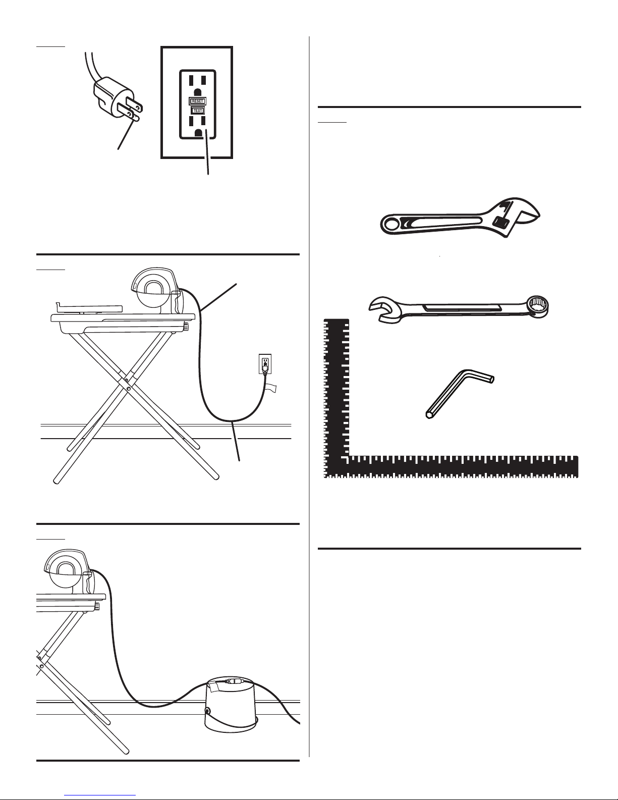
Fig. 1
NOTE: Figure 4 shown on page 17.
NOTE : Figure 4 montré sur la page 17.
NOTA: Figure 4 mostrado en la página 17.
A
B
A - Grounding pin (broche de mise à la terre, patilla de conexión a
tierra)
B - Ground fault circuit interrupter (GFCI) receptacle [prise de dispositif
interrupteur de défaut à la terre (GFCI), enchufe con interruptor de
circuito accionado por falla de conexión a tierra (GFCI)]
Fig. 2
A
Fig. 5
TOOLS NEEDED
OUTILS NÉCESSAIRES
HERRAMIENTAS NECESARIAS
A
B
B
A - Power cord (cordon d’alimentation, cordón de corriente)
B - Drip loop (boucle d’égouttement, vuelta de goteo)
Fig. 3
C
D
A - Adjustable wrench (clé a molette, llave ajustable)
B - 13 mm wrench (clé de 13 mm, llave de 13 mm)
C - 3 mm hex key (clé hexagonale de 3 mm, llave hexagonal de 3 mm)
D - Framing square (équerre de charpentier, escuadra de carpintero)
16
Page 17
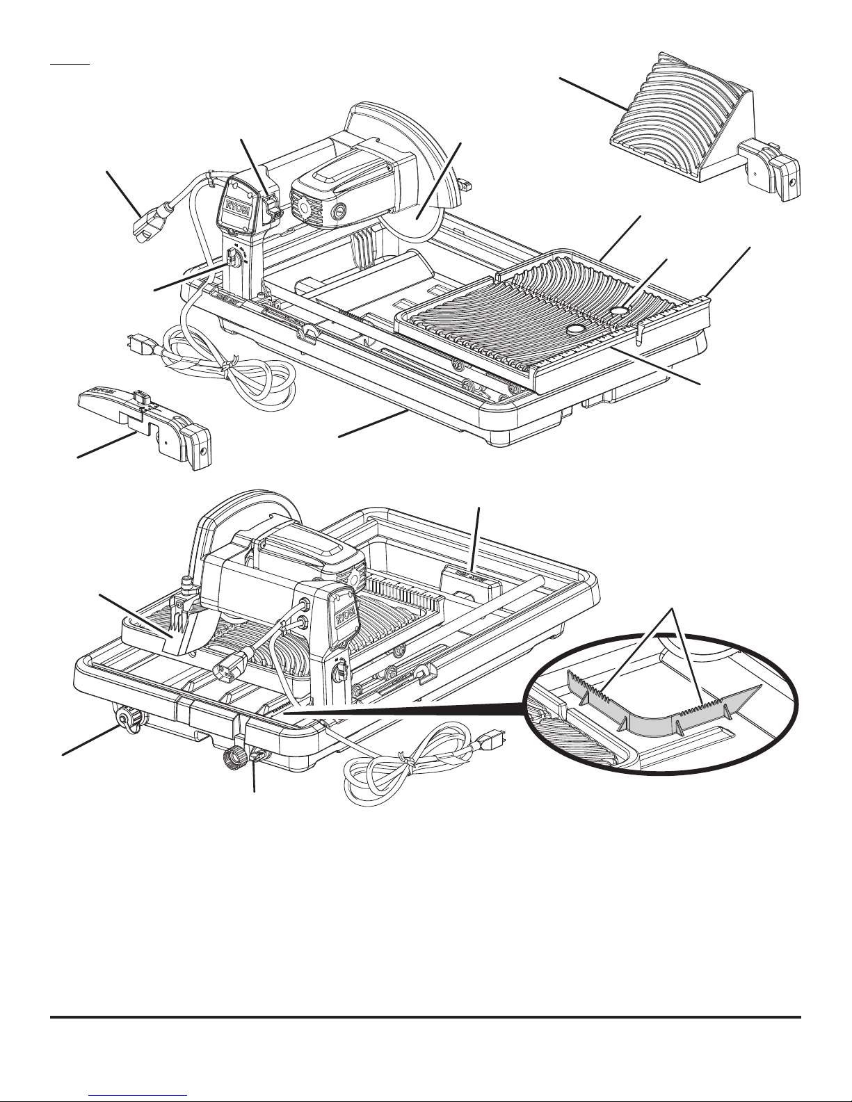
Fig. 4
L
J
K
I
M
N
O
H
P
F
G
E
D
C
B
A - CLEAN WAVE WALL™
B - Pan flow control valve (robinet de réglage de débit du bassin, válvula
de control de flujo de bandeja)
C - Drainage output cap (casquette de la sortie de vidanger, tapa de la
salida de desagüe)
D - Splash guard (protection éclabousser, protector para salpicaduras)
E - Max water fill line (l’eau maximum remplit la ligne, agua máxima llena
la línea)
F - Water tray (plateau d’eau, bandejas de agua)
G - Rip guide (guide de bord, guía de borde al hilo)
H - Arm flow control valve (levier de soupape de réglage de débit, válvula
de control de flujo de brazo)
A
I - Receptacle for optional pump (prise pour la pompe supplé mentaire,
receptáculo para la bomba opcional)
J - On/off switch (interrupteur marche/arrêt, interruptor de encendido/
apagado)
K - Tile cutting wheel (meule à carreaux, muela para cortar losas)
L - Bevel block (bois de biseau, bloque de bisel)
M
- EASY GLIDE™ table (plateau EASY GLIDE™, mesa EASY GLIDE™)
N - “NO HANDS” zone label (étiquette « MAINS À L’ÉCART », etiqueta
“ZONA DE NO ACERCAR LAS MANOS”)
O - Fence scale (échelle du guide, escala de la guía)
P - Fence (guide, guía)
17
Page 18
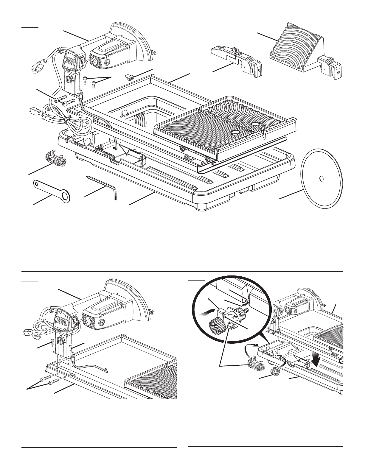
Fig. 6
I
LOOSE PARTS
PIÈCES DÉTACHÉES
B
PIEZAS SUELTAS
L
H
G
K
F
E
A - Tile cutting wheel (meule à carreaux, muela para cortar losas)
B - Bevel block (bois de biseau, bloque de bisel)
C - Rip guide (guide de bord, guía de borde al hilo)
D - Water tray (plateau d’eau, bandejas de agua)
E - Wheel wrench (clé de meule, llave de la muela)
F - 6 mm hex key (clé hexagonale de 6 mm, llave hexagonal de 6 mm)
G - Socket head screw (large) [vis à tête creuse (entretoise), tornillo de
cabeza hueca (grande)]
D
J
C
A
H - Socket head screw (small) [vis à tête creuse (petite), tornillo
de cabeza hueca (pequeña)]
I - Motor head assembly (ensemble du moteur de tête, conjunto
del motor de cabeza)
J - Water tray frame (bâti d’eau, agua en la armazón)
K - Pan flow control valve (robinet de réglage de débit du bassin, válvula de
control de flujo de bandeja)
L - Switch key (clé de commutateur, llave del interruptor)
Fig. 7
B
A
A
D
A - Small socket head screw (petite vis de tête creuse, pequeño tornillo de
cabeza hueca)
B - Motor head assembly (ensemble du moteur de tête, conjunto del motor
de cabeza)
C - Water tray frame (bâti d’eau, agua en la armazón)
D - Large socket head screw (grande vis de tête creuse, grande tornillo de
cabeza hueca]
C
Fig. 8
F
E
H
G
C
D
A - Water tray frame (bâti d’eau, agua en la armazón)
B - Water tray (plateau d’eau, bandejas de agua)
C - Pan flow control valve (robinet de réglage de débit du bassin, válvula de
control de flujo de bandeja)
D - Water supply valve cap (capuchon de arroser la soupape de provision,
tapa de la válvula de suministro de agua)
E - Valve lip (lèvre du clapet, borde de la válvula)
F - Tray ledge (appui du plateau, reborde de la bandeja)
G - Rib (côte, costilla)
H - Notch (encoche, muesca)
B
A
18
Page 19
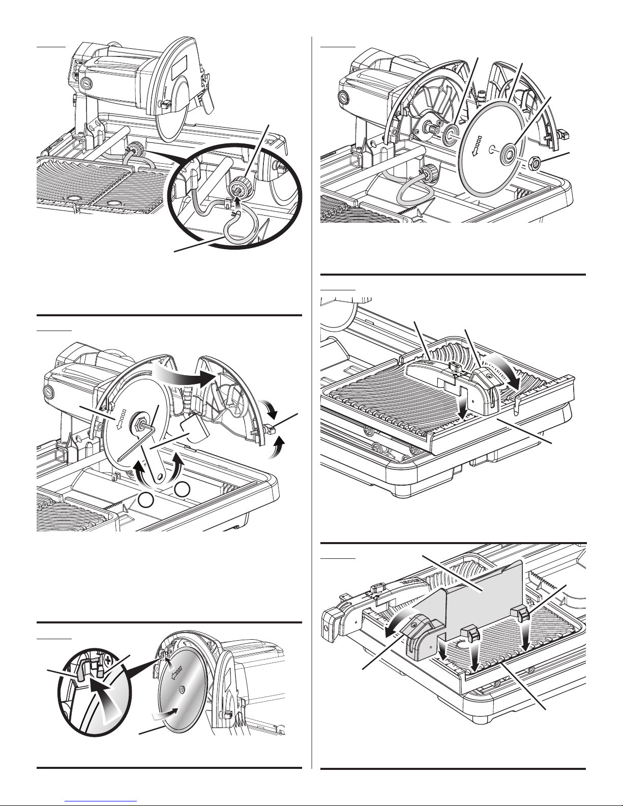
Fig. 9
A
B
A - Pan flow control valve (robinet de réglage de débit du bassin, válvula de
control de flujo de bandeja)
B - Clear hose (flexible d’injection transparent, manguera de inyección
transparente)
Fig. 10
Fig. 12
A
A - Inner washer (rondelle intérieur, arandela interior)
B - Tile cutting wheel (meule à carreaux, muela para cortar losas)
C - Outer washer (rondelle extérieure, arandela exterior)
D - Arbor nut (écrou d’arbre, tuerca del árbol)
B
Fig. 13
A
B
C
D
D
E
B
F
C
B
C
A - Wheel guard lock (protège-meule de blocage, protección para
la muela de fijación)
B - To loosen (pour desserrer, para aflojar)
C - To tighten (pour serrer, para ajustar)
D - Tile cutting wheel (meule à carreaux, muela para cortar losas)
E - Hex key (clé hexagonale, llave hexagonal)
F - Wheel wrench (clé de meule, llave de la muela)
Fig. 11
B
B
A
A - Rip guide (guide de bord, guía de borde al hilo)
B - Lever (levier, palanca)
C - Fence (guide, guía)
Fig. 14
B
A
C
D
A
A - Tile cutting wheel (meule à carreaux, muela para cortar losas)
B - Water nozzles (buses d’eau, boquillas de agua)
C
A - Lever (levier, palanca)
B - Bevel block (bois de biseau, bloque de bisel)
C - Slot (fente, ranura)
D - Bevel block tab (bois de biseau la languette, bloque de bisel la orejeta)
19
Page 20
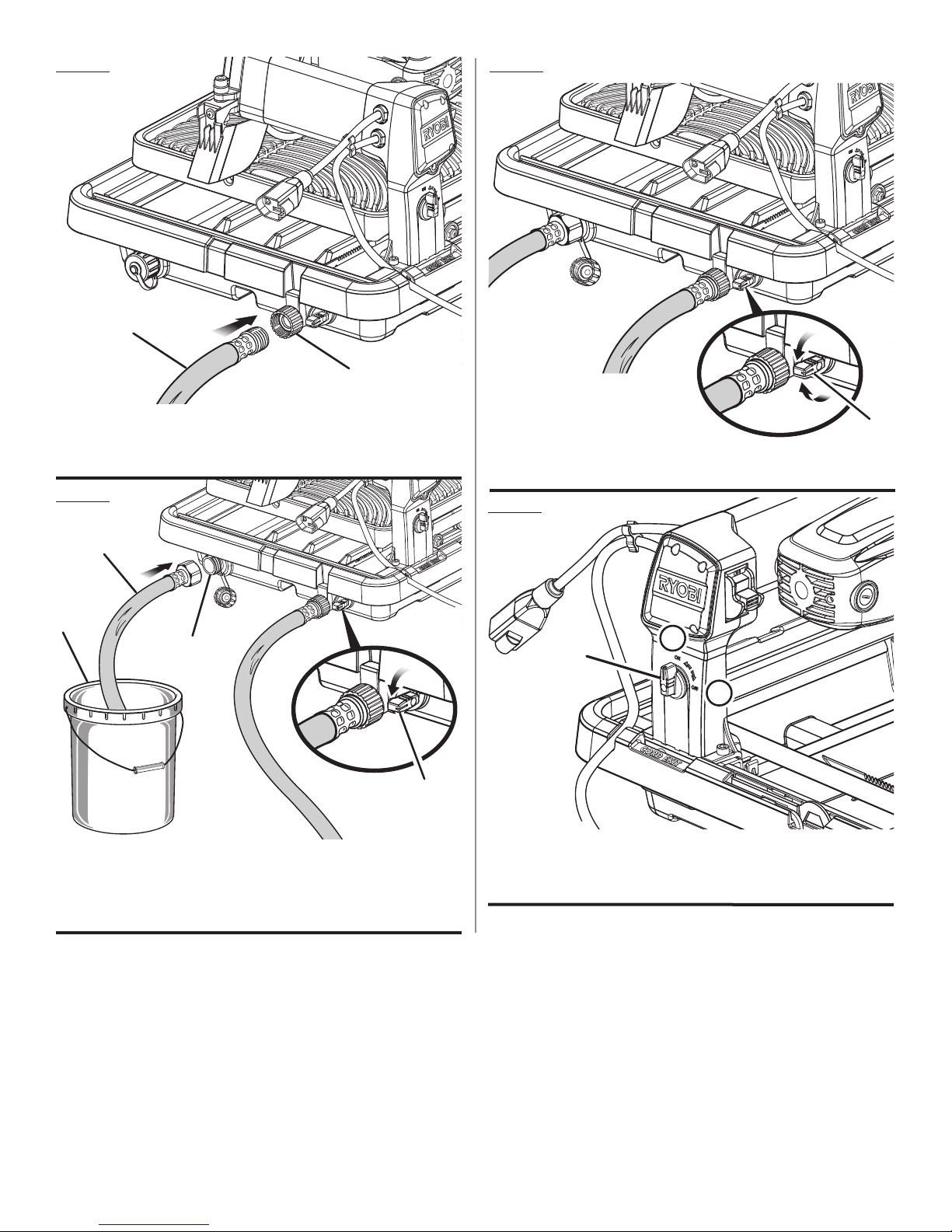
Fig. 15
Fig. 17
B
A
A - Pan flow control valve (robinet de réglage de débit du bassin, válvula de
control de flujo de bandeja)
B - Garden hose (tuyau d’arrosage, manguera de jardín)
Fig. 16
B
A
C
D
A - Bucket (seau, balde)
B - Drainage hose (tuyau de vidanger, manguera de desagüe)
C - Drainage output (sortie de drainage, salida de desagüe)
D- Pan flow control valve (robinet de réglage de débit du bassin, válvula de
control de flujo de bandeja)
A
A - Pan flow control valve (robinet de réglage de débit du bassin, válvula
de control de flujo de bandeja)
Fig. 18
C
B
A
A - Off (arrêt, apagado)
C - Arm flow control valve (levier de soupape de réglage de débit, válvula
de control de flujo de brazo)
C - On (marche, encendido)
20
Page 21
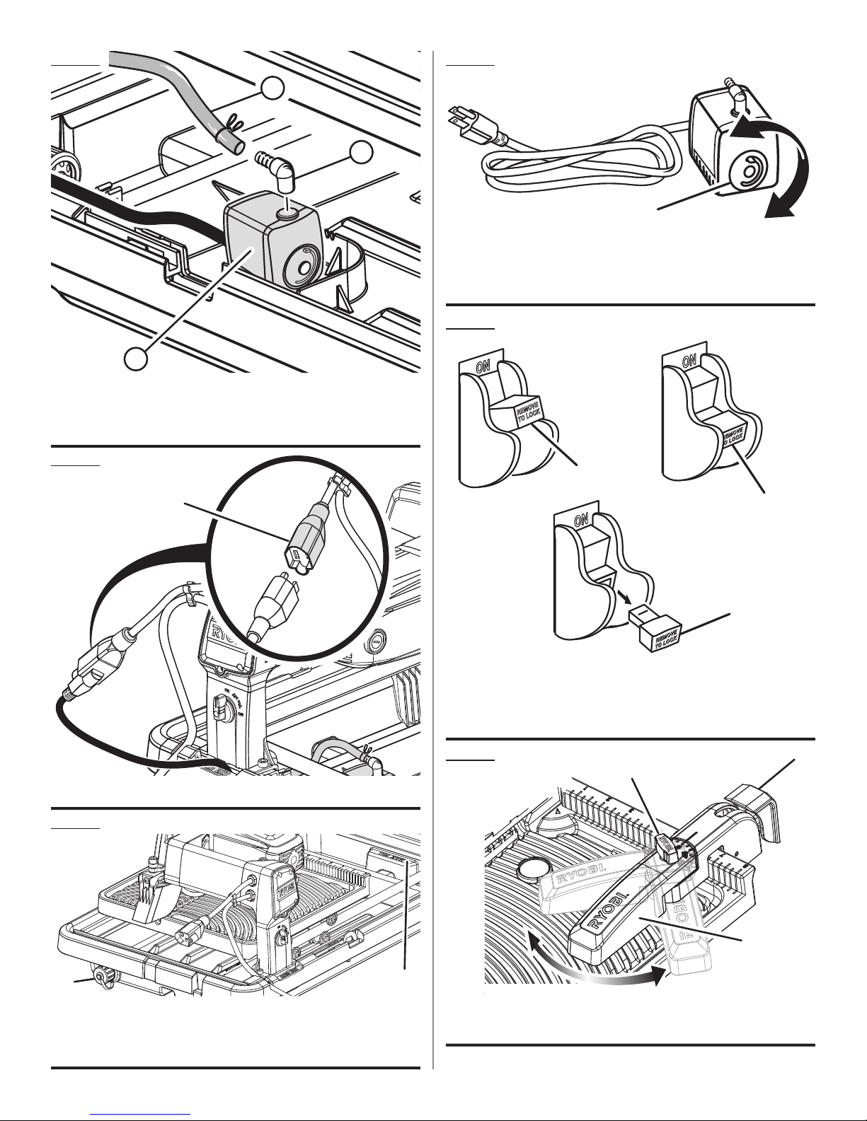
Fig. 19
Fig. 22
A
B
C
A - Clear hose (transparent le tuyau, manguera transparente)
B - 90° fitting (raccord de 90°, conexión de 90°)
C - Water pump (not included) [pompe d’eau (non incluses), bomba de
agua (no incluye)]
Fig. 20
A
B
MAX
MIN
A
A - Water flow selector (sélecteur d’eau le flux, control de agua el flujo)
B - Max (maximales, máx.)
C - Min (minimales, mín.)
C
Fig. 23
A
B
A - Rubber boot (gaine caoutchoutée, botas de goma)
Fig. 21
A
A - Drainage output cap (casquette de la sortie de vidanger, tapa de la
salida de desagüe)
B - Max water fill line (l’eau maximum remplit la ligne, agua máxima llena
la línea)
B
C
A - Switch on (commutateur en position de marche, interruptor en posición
de encendidoI)
B - Switch off (commutateur en position d"arrôt, interruptor en posición
de apagado)
C - Switch key removed (clé de commutateur, llave del interruptor retirada)
Fig. 24
C
B
A
A - Rip guide (guide de bord, guía de borde al hilo)
B - Lock knob (bouton de verrouillage, perilla de fijación)
C - Lever (levier, palanca)
21
Page 22
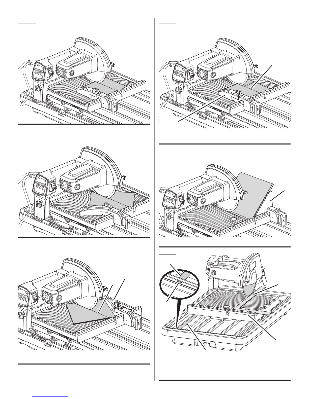
Fig. 25
RIP CUT
(COUPE LONGITUDINALE,
CORTES AL HILO)
Fig. 28
L-CUT
(COUPE D’ONGLET,
CORTE A INGLETE)
A
B
Fig. 26
Fig. 27
DIAGONAL CUT
(COUPE EN DIAGONALE,
CORTE DIAGONALE)
MITER CUT
(COUPE D’ONGLET,
CORTE A INGLETE)
A - Mark (marquer, marca)
B - Rip guide (guide de bord, guía de borde al hilo)
Fig. 29
A - Bevel block (bois de biseau, bloque de bisel)
BEVEL CUT
(COUPE EN BISEAU,
CORTE EN BISEL)
A
Fig. 30
B
B
A
D
A - Mark (marquer, marca)
B - Rip guide (guide de bord, guía de borde al hilo)
A
C
B
A - Hex bolt (boulon hex, perno hexagona)
B - Slide rod (tige de coulisse, barra de la corredera)
C - Fence (guide, guía)
D - Framing square (équerre de charpentier, escuadra de carpintero)
22
Page 23
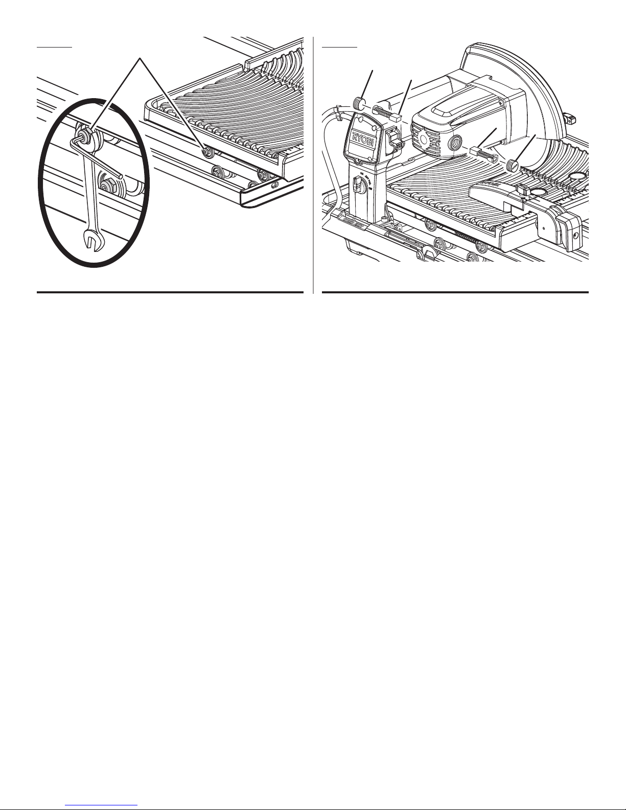
Fig. 31 Fig. 32
A
A
B
A - Cam bolt nut (écrou de boulon de came, tuerca de perilla de leva)
B
A - Brush cap (couvercle de balai, tapa de la escobilla)
B - Brush assembly (balai, conjunto de la escobilla)
A
23
Page 24
OPERATOR’S MANUAL/7 in. TILE SAW
MANUEL D’UTILISATION/SCIE À CARREAUX DE 178 mm (7 po)
MANUAL DEL OPERADOR/SIERRA DE LOSAS DE 178 mm (7 pulg.)
WS731
To request service, purchase replacement parts,
locate an Authorized Service Center and obtain Customer or Technical Support:
Visit www.ryobitools.com or call 1-800-525-2579
If any parts or accessories are damaged or missing,
do not return this product to the store. Call 1-800-525-2579 for immediate service.
Please obtain your model and serial number from the product data plate.
This product is covered under a 3-year limited Warranty. Proof of purchase is required.
MODEL NUMBER _______________ SERIAL NUMBER ____________________________
RYOBI is a registered trademark of Ryobi Limited and is used pursuant to a license granted by Ryobi Limited.
Pour faire une demande de réparations ou obtenir des pièces de rechange, trouver un
Centre de réparations agréé pour obtenir un soutien technique ou le Service à la clientèle :
Visiter www.ryobitools.com ou en téléphonant au 1-800-525-2579
Si des pièces ou accessoires sont manquantes ou endommagées, ne pas retourner
ce produit au magasin. Appeler immédiatement au 1-800-525-2579 pour obtenir de l’aide.
Inscrire les numéros de modèle et de série inscrits sur la plaque d’identification du produit.
Ce produit est couvert par une garantie limitée de trois (3) ans. Une preuve d’achat est exigée.
NUMÉRO DE MODÈLE _______________ NUMÉRO DE SÉRIE ____________________________
RYOBI est une marque déposée de Ryobi Limited et est utilisée en vertu d’une licence accordée par Ryobi Limited.
Para obtener servicio, comprar piezas de repuesto, localizar un centro de servicio autorizado
y obtener Servicio o Asistencia Técnica al Consumidor:
Visite www.ryobitools.com o llame al 1-800-525-2579
Si hay alguna pieza ou accesorios dañada o faltante, no devuelva este producto a la tienda.
Llame al 1-800-525-2579 para servicio técnico inmediato.
Obtenga su modelo y número de serie de la placa de datos del producto.
Este producto está cubierto con una garantía limitada de 3 años. Se solicita prueba de la compra.
NÚMERO DE MODELO _______________ NÚMERO DE SERIE ____________________________
RYOBI es una marca registrada de Ryobi Limited y se utiliza conforme a una licencia otorgada por Ryobi Limited.
1428 Pearman Dairy Road, Anderson, SC 29625 • Phone 1-800-525-2579
États-Unis, Téléphone 1-800-525-2579 • USA, Teléfono 1-800-525-2579
991000680
12-1-15 (REV:02)
ONE WORLD TECHNOLOGIES, INC.
www.ryobitools.com
24
 Loading...