

Page 1
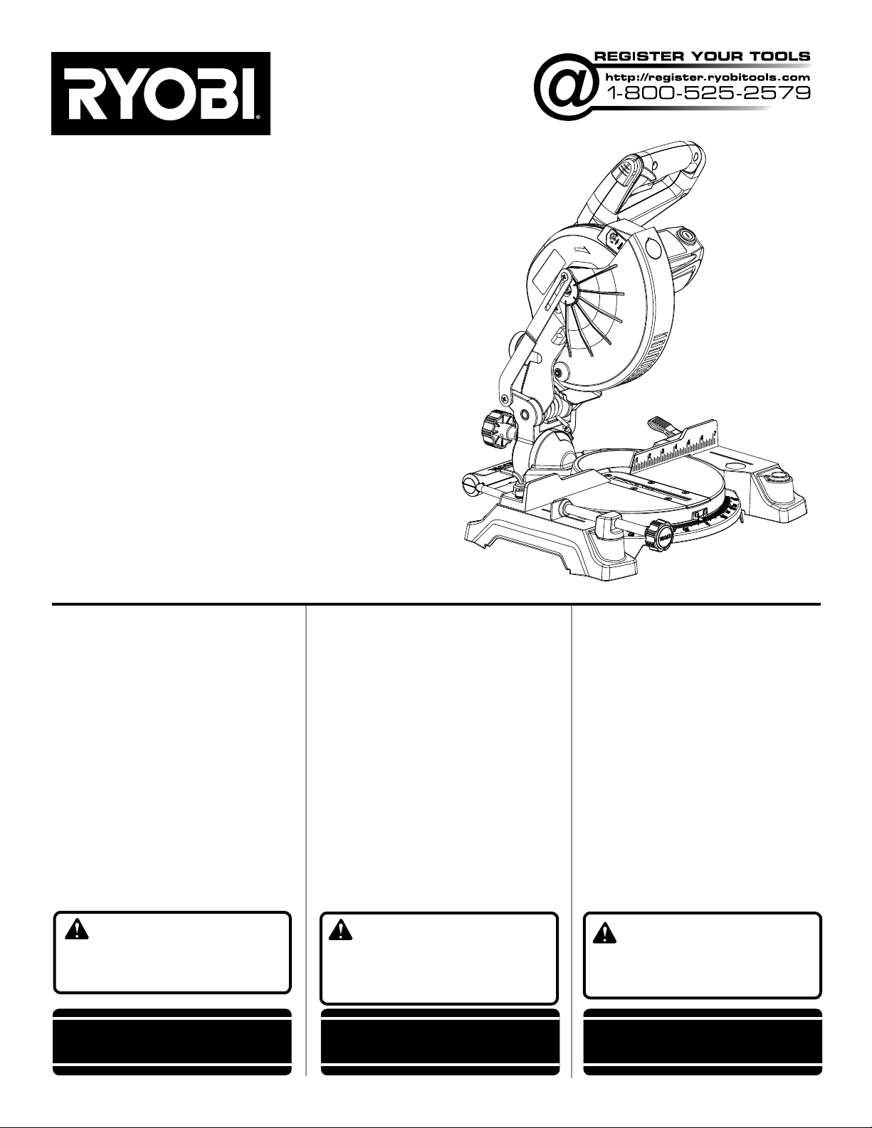
OPERATOR’S MANUAL
MANUEL D’UTILISATION
MANUAL DEL OPERADOR
7-1/4 in. COMPOUND MITER SAW
Double insulated
SCIE À ONGLETS COMPOSÉS DE
184 mm (7-1/4 po),
SIERRA INGLETEADORA COMPUESTA
DESLIZANTE DE 184 mm (7-1/4 pulg.),
Doble aislamiento
TS1143L
Double isolation
TABLE OF CONTENTS
General Safety Rules .......................2-3
Specific Safety Rules ......................3-4
Symbols ..............................................5
Electrical ............................................. 6
Glossary .............................................7
Features .........................................8-10
Tools needed .................................... 10
Loose Parts ......................................11
Assembly .....................................12-18
Operation .....................................19-25
Adjustments ................................26-27
Maintenance ..................................... 28
Parts Ordering / Service ......Back page
WARNING: To reduce the
risk of injury, the user must read and
understand the operator’s manual
before using this product.
SAVE THIS MANUAL FOR
FUTURE REFERENCE
TABLE DES MATIÈRES
Règles de sécurité générales ..........2-3
Règles de sécurité particulières ......3-4
Symboles ............................................5
Caractéristiques électriques ............... 6
Glossaire .............................................7
Caractéristiques ............................8-10
Outils nécessaires ............................10
Liste des pièces detachées .............. 11
Assemblage .................................12-18
Utilisation .....................................19-25
Réglages ......................................26-27
Entretien ...........................................28
Commande de pièces
et dépannage ....................Page arrière
AVERTISSEMENT :
réduire les risques de blessures,
l’utilisateur doit lire et veiller à bien
comprendre le manuel d’utilisation avant
d’employer ce produit.
Pour
CONSERVER CE MANUEL
POUR FUTURE RÉFÉRENCE
ÍNDICE DE CONTENIDO
Reglas de seguridad generales .......2-3
Reglas de seguridad específicas ....3-4
Símbolos ............................................5
Aspectos eléctricos ............................ 6
Glosario de términos .......................... 7
Características ..............................8-10
Herramientas necesarias .................. 10
Lista de piezas sueltas ..................... 11
Armado ........................................12-18
Funcionamiento ...........................19-25
Ajustes .........................................26-27
Mantenimiento ..................................28
Pedidos de piezas
y servicio ....................... Pág. posterior
ADVERTENCIA: Para reducir
el riesgo de lesiones, el usuario debe leer
y comprender el manual del operador
antes de usar este producto.
GUARDE ESTE MANUAL
PARA FUTURAS CONSULTAS
Page 2

GENERAL SAFETY RULES
WARNING:
Read and understand all instructions. Failure to follow
all instructions listed below, may result in electric shock,
fire and/or serious personal injury.
READ ALL INSTRUCTIONS
KNOW YOUR POWER TOOL. Read the operator’s manual
carefully. Learn the applications and limitations as well
as the specific potential hazards related to this tool.
GUARD AGAINST ELECTRICAL SHOCK BY PREVENT-
ING BODY CONTACT WITH GROUNDED SURFACES.
For example: pipes, radiators, ranges, refrigerator enclosures.
KEEP GUARDS IN PLACE and in good working order.
REMOVE ADJUSTING KEYS AND WRENCHES. Form
habit of checking to see that keys and adjusting wrenches
are removed from tool before turning it on.
KEEP WORK AREA CLEAN. Cluttered areas and benches
invite accidents. DO NOT leave tools or pieces of wood
on the tool while it is in operation.
DO NOT USE IN DANGEROUS ENVIRONMENTS. Do
not use power tools in damp or wet locations or expose
to rain. Keep the work area well lit.
KEEP CHILDREN AND VISITORS AWAY. All
visitors should wear safety glasses and be kept a safe
distance from work area. Do not let visitors contact
tool or extension cord while operating.
MAKE WORKSHOP CHILDPROOF with padlocks,
master switches, or by removing starter keys.
DON’T FORCE THE TOOL. It will do the job better and
safer at the feed rate for which it was designed.
USE THE RIGHT TOOL. Do not force the tool or attach-
ment to do a job for which it was not designed.
USE THE PROPER EXTENSION CORD. Make sure your
extension cord is in good condition. Use only a cord heavy
enough to carry the current your product will draw. An
undersized cord will cause a drop in line voltage resulting in loss of power and overheating. A wire gauge size
(A.W.G.) of at least 14 is recommended for an extension
cord 50 feet or less in length. If in doubt, use the next
heavier gauge. The smaller the gauge number, the heavier
the cord.
DRESS PROPERLY. Do not wear loose clothing,
neckties, or jewelry that can get caught and draw you into
moving parts. Rubber gloves and nonskid footwear are
recommended when working outdoors. Also wear
protective hair covering to contain long hair.
ALWAYS WEAR SAFETY GLASSES WITH SIDE
SHIELDS. Everyday eyeglasses have only impact-
resistant lenses, they are NOT safety glasses.
SECURE WORK. Use clamps or a vise to hold work
when practical, it is safer than using your hand and frees
both hands to operate the tool.
DO NOT OVERREACH. Keep proper footing and
balance at all times.
MAINTAIN TOOLS WITH CARE. Keep tools sharp
and clean for better and safer performance. Follow
instructions for lubricating and changing accessories.
DISCONNECT TOOLS. When not in use, before
servicing, or when changing attachments, blades, bits,
cutters, etc., all tools should be disconnected from power
source.
AVOID ACCIDENTAL STARTING. Be sure switch is off
when plugging in any tool.
USE RECOMMENDED ACCESSORIES. Consult the
operator’s manual for recommended accessories. The
use of improper accessories may result in injury.
NEVER STAND ON TOOL. Serious injury could occur if
the tool is tipped or if the cutting tool is unintentionally
contacted.
CHECK DAMAGED PARTS. Before further use of the
tool, a guard or other part that is damaged should be
carefully checked to determine that it will operate properly
and perform its intended function. Check for alignment
of moving parts, binding of moving parts, breakage of
parts, mounting and any other conditions that may affect
its operation. A guard or other part that is damaged must
be properly repaired or replaced by an authorized service
center to avoid risk of personal injury.
USE THE RIGHT DIRECTION OF FEED. Feed work into
a blade or cutter against the direction of rotation of the
blade or cutter only.
NEVER LEAVE TOOL RUNNING UNATTENDED. TURN
THE POWER OFF. Don’t leave tool until it comes to a
complete stop.
PROTECT YOUR LUNGS. Wear a face or dust mask if
the cutting operation is dusty.
PROTECT YOUR HEARING. Wear hearing protection
during extended periods of operation.
DO NOT ABUSE CORD. Never carry tool by the cord or
yank it to disconnect from receptacle. Keep cord from
heat, oil, and sharp edges.
USE OUTDOOR EXTENSION CORDS. When tool
is used outdoors, use only extension cords with
approved ground connection that are intended for use
outdoors and so marked.
KEEP BLADES CLEAN, SHARP, AND WITH
SUFFICIENT SET. Sharp blades minimize stalling
and kickback.
BLADE COASTS AFTER BEING TURNED OFF.
2
Page 3

GENERAL SAFETY RULES
NEVER USE IN AN EXPLOSIVE ATMOSPHERE.
Normal sparking of the motor could ignite fumes.
INSPECT TOOL CORDS PERIODICALLY. If
damaged, have repaired by a qualified service technician at
an authorized service facility. Repair or replace a damaged
or worn cord immediately. Stay constantly aware of cord
location and keep it well away from the rotating blade.
INSPECT EXTENSION CORDS PERIODICALLY and
replace if damaged.
POLARIZED PLUGS. To reduce the risk of electric shock,
this tool has a polarized plug (one blade is wider than
the other). This plug will fit in a polarized outlet only one
way. If the plug does not fit fully in the outlet, reverse the
plug. If it still does not fit, contact a qualified electrician
to install the proper outlet. Do not change the plug in any
way.
KEEP TOOL DRY, CLEAN, AND FREE FROM OIL AND
GREASE. Always use a clean cloth when cleaning. Never
use brake fluids, gasoline, petroleum-based products, or
any solvents to clean tool.
STAY ALERT AND EXERCISE CONTROL. Watch what
you are doing and use common sense. Do not operate
tool when you are tired. Do not rush.
DO NOT USE TOOL IF SWITCH DOES NOT TURN IT
ON AND OFF. Have defective switches replaced by an
authorized service center.
USE ONLY CORRECT BLADES. Do not use blades with
incorrect size holes. Never use blade washers or blade
bolts that are defective or incorrect. The maximum blade
capacity of your saw is 7-1/4 in.
BEFORE MAKING A CUT, BE SURE ALL ADJUST-
MENTS ARE SECURE.
BE SURE BLADE PATH IS FREE OF NAILS. Inspect for
and remove all nails from lumber before cutting.
NEVER TOUCH BLADE or other moving parts during
use.
NEVER START A TOOL WHEN ANY ROTATING COM-
PONENT IS IN CONTACT WITH THE WORKPIECE.
DO NOT OPERATE A TOOL WHILE UNDER THE
INFLUENCE OF DRUGS, ALCOHOL, OR ANY
MEDICATION.
WHEN SERVICING use only identical replacement parts.
Use of any other parts may create a hazard or cause
product damage.
USE ONLY RECOMMENDED ACCESSORIES listed
in this manual or addendums. Use of accessories that
are not listed may cause the risk of personal injury.
Instructions for safe use of accessories are included
with the accessory.
DOUBLE CHECK ALL SETUPS. Make sure blade is
tight and not making contact with saw or workpiece
before connecting to power supply.
SPECIFIC SAFETY RULES
FIRMLY CLAMP OR BOLT your tool to a workbench or
table at approximately hip height.
KEEP HANDS AWAY FROM CUTTING AREA. Do not
reach underneath work or in blade cutting path with your
hands and fingers for any reason. Always turn the power
off.
ALWAYS SUPPORT LONG WORKPIECES while cutting
to minimize risk of blade pinching and kickback. Saw may
slip, walk or slide while cutting long or heavy boards.
ALWAYS USE A CLAMP to secure the workpiece when
possible.
BE SURE THE BLADE CLEARS THE WORKPIECE.
Never start the saw with the blade touching the
workpiece. Allow motor to come up to full speed
before starting cut.
NEVER cut more than one piece at a time. DO NOT
STACK more than one workpiece on the saw table at a
time.
MAKE SURE THE MITER TABLE AND SAW ARM
(BEVEL FUNCTION) ARE LOCKED IN POSITION
BEFORE OPERATING YOUR SAW. Lock the miter
table by securely tightening the miter lock handle. Lock
the saw arm (bevel function) by securely tightening the
bevel lock knob.
NEVER USE A LENGTH STOP ON THE FREE SCRAP
END OF A CLAMPED WORKPIECE. NEVER hold onto
or bind the free scrap end of the workpiece in any operation. If a work clamp and length stop are used together,
they must both be installed on the same side of the saw
table to prevent the saw from catching the loose end and
kicking up.
NEVER PERFORM ANY OPERATION FREEHAND.
Always place the workpiece to be cut on the miter table
and position it firmly against the fence as a backstop.
Always use the fence.
NEVER hand hold a workpiece that is too small to be
clamped. Keep hands clear of the cutting area.
3
Page 4

SPECIFIC SAFETY RULES
NEVER reach behind, under, or within three inches of the
blade and its cutting path with hands and fingers for any
reason.
NEVER reach to pick up a workpiece, a piece of scrap,
or anything else that is in or near the cutting path of the
blade.
NEVER move the workpiece or make adjustment to any
cutting angle while the saw is running and the blade is
rotating. Any slip can result in contact with the blade
causing serious personal injury.
AVOID AWKWARD OPERATIONS AND HAND
POSITIONS where a sudden slip could cause your
hand to move into the blade. ALWAYS make sure you
have good balance. NEVER operate the miter saw
on the floor or in a crouched position.
NEVER stand or have any part of the body in line with
the path of the saw blade.
ALWAYS release the power switch and allow the saw blade
to stop rotating before raising it out of the workpiece.
DO NOT TURN THE MOTOR SWITCH ON AND OFF
RAPIDLY. This could cause the saw blade to loosen
and could create a hazard. Should this ever occur,
stand clear and allow the saw blade to come to a
complete stop. Disconnect your saw from the power
supply and securely retighten the blade bolt.
IF ANY PART OF THIS MITER SAW IS MISSING or
should break, bend, or fail in any way, or should any
electrical component fail to perform properly, shut off
the power switch, remove the miter saw plug from the
power source and have damaged, missing, or failed parts
replaced before resuming operation.
ALWAYS STAY ALERT! Do not allow familiarity (gained
from frequent use of the saw) to cause a careless
mistake. ALWAYS REMEMBER that a careless frac-
tion of a second is sufficient to inflict severe injury.
IF THE POWER SUPPLY CORD IS DAMAGED, it must
be replaced only by the manufacturer or by an authorized
service center to avoid risk.
MAKE SURE THE WORK AREA HAS AMPLE LIGHTING
to see the work and that no obstructions will interfere with
safe operation BEFORE performing any work using the
saw.
ALWAYS TURN OFF THE SAW before disconnecting it
to avoid accidental starting when reconnecting to power
supply. NEVER leave the saw unattended while connected
to a power source.
TURN OFF TOOL and wait for saw blade to come to
a complete stop before moving workpiece or changing
settings.
THIS TOOL should have the following markings:
a) Wear eye protection.
b) Keep hands out of path of saw blade.
c) Do not operate saw without guards in place.
d) Do not perform any operation freehand.
e) Never reach around saw blade.
f) Turn off tool and wait for saw blade to stop before
moving workpiece or changing settings.
g) Disconnect power (or unplug tool as applicable)
before changing blade or servicing.
h) No load speed.
ALWAYS carry the tool only by the “D” handle.
AVOID direct eye exposure when using the laser guide.
THIS SAW CAN TIP OVER if the saw head is released
suddenly and the saw is not secured to a work surface. ALWAYS secure this saw to a stable work surface before any use to avoid serious personal injury.
SAVE THESE INSTRUCTIONS. Refer to them
frequently and use to instruct other users. If you loan
someone this tool, loan them these instructions also.
4
Page 5
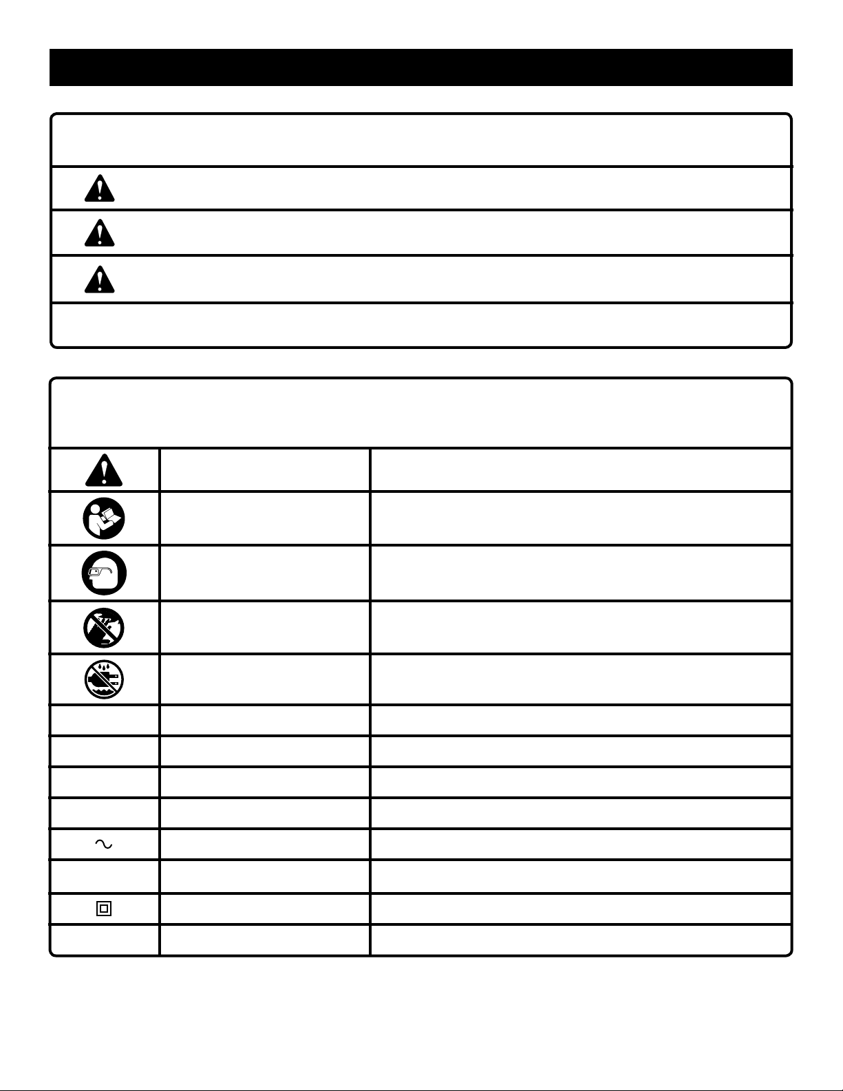
SYMBOLS
The following signal words and meanings are intended to explain the levels of risk associated with this product.
SYMBOL SIGNAL MEANING
DANGER:
WARNING:
CAUTION:
NOTICE:
Some of the following symbols may be used on this tool. Please study them and learn their meaning. Proper interpretation
of these symbols will allow you to operate the tool better and safer.
Indicates an imminently hazardous situation, which, if not avoided, will result
in death or serious injury.
Indicates a potentially hazardous situation, which, if not avoided, could result
in death or serious injury.
Indicates a potentially hazardous situation, which, if not avoided, may result
in minor or moderate injury.
(Without Safety Alert Symbol) Indicates important information not related
to an injury hazard, such as a situation that may result in property damage.
SYMBOL NAME DESIGNATION/EXPLANATION
Safety Alert Indicates a potential personal injury hazard.
Read Operator’s Manual
Eye Protection
To reduce the risk of injury, user must read and understand operator’s manual before using this product.
Always wear eye protection with side shields marked to comply
with ANSI Z87.1.
V
A
Hz
min
n
o
.../min
No Hands Symbol
Wet Conditions Alert Do not expose to rain or use in damp locations.
Volts Voltage
Amperes Current
Hertz Frequency (cycles per second)
Minutes Time
Alternating Current Type of current
No Load Speed Rotational speed, at no load
Class II Construction Double-insulated construction
Per Minute Revolutions, strokes, surface speed, orbits etc., per minute
Failure to keep your hands away from the blade will result in
serious personal injury.
5
Page 6
ELECTRICAL
DOUBLE INSULATION
Double insulation is a concept in safety in electric power tools,
which eliminates the need for the usual three-wire grounded
power cord. All exposed metal parts are isolated from the
internal metal motor components with protecting insulation.
Double insulated tools do not need to be grounded.
WARNING:
The double insulated system is intended to protect the
user from shock resulting from a break in the tool’s internal wiring. Observe all normal safety precautions to
avoid electrical shock.
NOTE: Servicing of a product with double insulation requires
extreme care and knowledge of the system and should be
performed only by a qualified service technician. For service,
we suggest you return the tool to your nearest authorized
service center for repair. Always use original factory replacement parts when servicing.
ELECTRICAL CONNECTION
This tool has a precision-built electric motor. It should be
connected to a power supply that is 120 volts, AC only
(normal household current), 60 Hz. Do not operate this tool
on direct current (DC). A substantial voltage drop will cause
a loss of power and the motor will overheat. If the tool does
not operate when plugged into an outlet, double-check the
power supply.
EXTENSION CORDS
When using a power tool at a considerable distance from
a power source, be sure to use an extension cord that has
the capacity to handle the current the product will draw. An
undersized cord will cause a drop in line voltage, resulting in
overheating and loss of power. Use the chart to determine
the minimum wire size required in an extension cord. Only
round jacketed cords listed by Underwriter’s Laboratories
(UL) should be used.
When working outdoors with a product, use an extension
cord that is designed for outside use. This type of cord is
designated with “WA” or “W” on the cord’s jacket.
Before using any extension cord, inspect it for loose or
exposed wires and cut or worn insulation.
**Ampere rating (on product data plate)
0-2.0 2.1-3.4 3.5-5.0 5.1-7.0 7.1-12.0 12.1-16.0
Cord Length Wire Size (A.W.G.)
25' 16 16 16 16 14 14
50' 16 16 16 14 14 12
100' 16 16 14 12 10 —
**Used on 12 gauge - 20 amp circuit
NOTE: AWG = American Wire Gauge
WARNING:
Keep the extension cord clear of the working area.
Position the cord so that it will not get caught on lumber,
tools, or other obstructions while you are working with
a power tool. Failure to do so can result in serious personal injury.
WARNING:
Check extension cords before each use. If damaged
replace immediately. Never use tool with a damaged cord
since touching the damaged area could cause electrical
shock resulting in serious injury.
6
Page 7

GLOSSARY OF TERMS
Anti-Kickback Pawls (radial arm and table saws)
A device which, when properly installed and maintained,
is designed to stop the workpiece from being kicked back
toward the front of the saw during a ripping operation.
Arbor
The shaft on which a blade or cutting tool is mounted.
Bevel Cut
A cutting operation made with the blade at any angle other
than 90° to the table surface.
Compound Cut
A cross cut made with both a miter and a bevel angle.
Cross Cut
A cutting or shaping operation made across the grain or the
width of the workpiece.
Cutterhead (planers and jointer planers)
A rotating cutterhead with adjustable blades or knives. The
blades or knives remove material from the workpiece.
Dado Cut
A non-through cut which produces a square-sided notch or
trough in the workpiece (requires a special blade).
Featherboard
A device used to help control the workpiece by holding
it securely against the table or fence during any ripping
operation.
FPM or SPM
Feet per minute (or strokes per minute), used in reference
to blade movement.
Freehand
Performing a cut without the workpiece being guided by a
fence, miter gauge, or other aids.
Gum
A sticky, sap-based residue from wood products.
Heel
Alignment of the blade to the fence.
Kerf
The material removed by the blade in a through cut or the
slot produced by the blade in a non-through or partial cut.
Kickback
A hazard that can occur when the blade binds or stalls,
throwing the workpiece back toward operator.
Miter Cut
A cutting operation made with the workpiece at any angle
to the blade other than 90°.
Non-Through Cuts
Any cutting operation where the blade does not extend
completely through the thickness of the workpiece.
Pilot Hole (drill presses)
A small hole drilled in a workpiece that serves as a guide for
drilling large holes accurately.
Push Blocks (for jointer planers)
Device used to feed the workpiece over the jointer planer
cutterhead during any operation. This aid helps keep the
operator’s hands well away from the cutterhead.
Push Blocks (for table saws)
Device used to hold the workpiece during cutting operations. This aid helps keep the operator’s hands well away
from the blade.
Push Sticks (for table saws)
Device used to push the workpiece during cutting operations.
A push stick should be used for narrow ripping operations.
The aid helps keep the operator’s hands well away from
the blade.
Resaw
A cutting operation to reduce the thickness of the workpiece
to make thinner pieces.
Resin
A sticky, sap-based substance that has hardened.
Revolutions Per Minute (RPM)
The number of turns completed by a spinning object in one
minute.
Ripping or Rip Cut
A cutting operation along the length of the workpiece.
Riving Knife/Spreader/Splitter (table saws)
A metal piece, slightly thinner than the blade, which helps
keep the kerf open and also helps to prevent kickback.
Saw Blade Path
The area over, under, behind, or in front of the blade. As it
applies to the workpiece, that area which will be or has been
cut by the blade.
Set
The distance that the tip of the saw blade tooth is bent (or
set) outward from the face of the blade.
Snipe (planers)
Depression made at either end of a workpiece by cutter
blades when the workpiece is not properly supported.
Taper Cut
A cut where the material being cut has a different width at
the beginning of the cut from the the end.
Through Sawing
Any cutting operation where the blade extends completely
through the thickness of the workpiece.
Throw-Back
The throwing back of a workpiece usually caused by the
workpiece being dropped into the blade or being placed
inadvertently in contact with the blade.
Workpiece or Material
The item on which the operation is being done.
Worktable
Surface where the workpiece rests while performing a
cutting, drilling, planing, or sanding operation.
7
Page 8
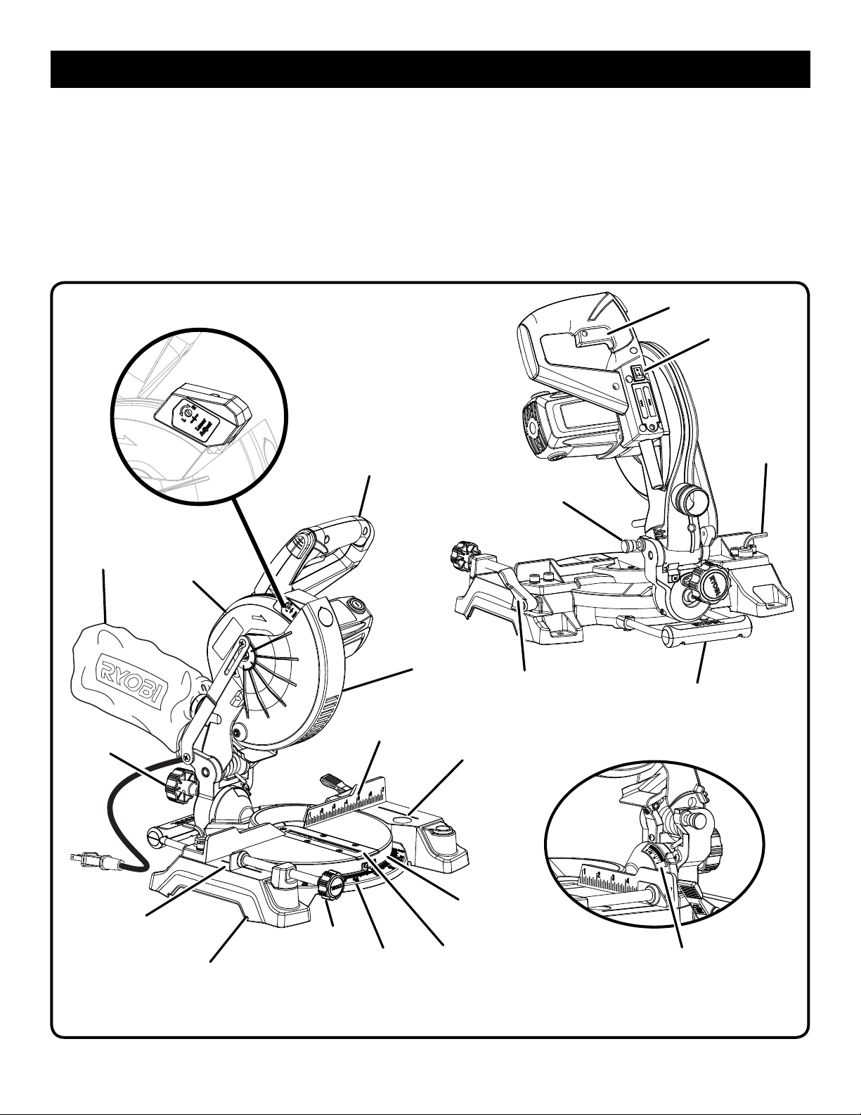
FEATURES
PRODUCT SPECIFICATIONS
Arbor ......................................................................... 5/8 in.
Blade Diameter ......................................................7-1/4 in.
No Load Speed ....................................5,800 r/min. (RPM)
Input .................................. 120 V, AC only, 60 Hz, 9 Amps
LASER
GUIDE
“D” HANDLE
Cutting Capacity with Miter at 0°/Bevel 0°:
Maximum lumber sizes ..................... 1-1/2 in. x 4-1/4 in.
Cutting Capacity with Miter at 45°/Bevel 0°:
Maximum lumber sizes ............................1-1/2 in. x 3 in.
Cutting Capacity with Miter at 0°/Bevel 45°:
Maximum lumber sizes ..................... 1-1/2 in. x 3-1/2 in.
Cutting Capacity with Miter at 45°/Bevel 45°:
Maximum lumber sizes ............................... 3/4 in. x 3 in.
SWITCH TRIGGER
LASER GUIDE
SWITCH
BLADE
WRENCH
LOCK PIN
DUST BAG
BEVEL
LOCK
KNOB
“NO HANDS ZONE”
BOUNDARY LINE
UPPER
BLADE
GUARD
BASE
WORK
CLAMP
MITER
FENCE
MITER
SCALE
LOWER
BLADE
GUARD
“NO HANDS ZONE”
LABEL
MITER
TABLE
THROAT
PLATE
MITER
LOCK LEVER
REAR BRACKET/
CARRYING HANDLE
BEVEL
SCALE
Fig. 1
8
Page 9
FEATURES
KNOW YOUR COMPOUND MITER SAW
See Figures 1 - 5.
The safe use of this product requires an understanding of
the information on the tool and in this operator’s manual as
well as a knowledge of the project you are attempting. Before
use of this product, familiarize yourself with all operating
features and safety rules.
9 AMP MOTOR
The saw has a powerful 9 amp motor with sufficient power to
handle tough cutting jobs. It is made with all ball bearings, and
has externally accessible brushes for ease of servicing.
7-1/4 in. BLADE
A 7-1/4 in. blade is included with the compound miter saw.
It will cut materials up to 1-1/2 in. thick or 4-1/4 in. wide,
depending upon the angle at which the cut is being made.
BEVEL LOCK KNOB
The bevel lock knob securely locks your compound miter
saw at desired bevel angles. Positive stop adjustment
screws have been provided on each side of the saw arm.
These adjustment screws are for making fine adjustments
at 0° and 45°.
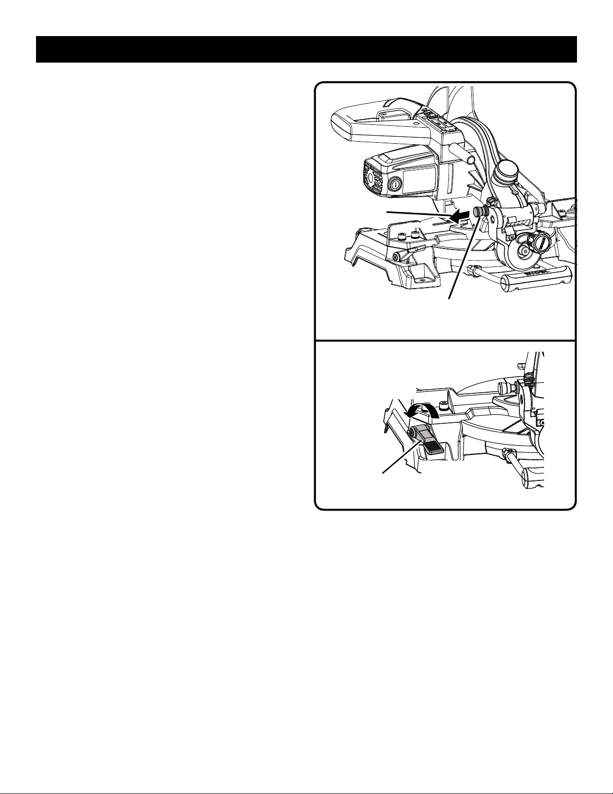
UNLOCK
LOCK PIN
SAW ARM LOCKED IN DOWN POSITION
Fig. 2
BLADE WRENCH STORAGE
A blade wrench is packed with the saw. One end of the
wrench is a phillips screwdriver and the other end is a hex
key. Use the hex key end when installing or removing blade
and the phillips end when removing or loosening screws. A
storage area for the blade wrench is located in the saw’s base.
DETENTS ON MITER TABLE
Detents have been provided at 0°, 15°, 22-1/2°, 31.62°, and
45°. The 15°, 22-1/2°, 31.62°, and 45° detents have been
provided on both the left and right side of the miter table.
LASER GUIDE
For more accurate cuts, a laser guide is included with your
miter saw. When used properly, the laser guide makes accurate, precision cutting simple and easy.
MITER FENCE
The miter fence on the compound miter saw has been
provided to hold your workpiece securely against when
making all cuts.
MITER LOCK LEVER
The miter lock lever securely locks the saw at desired miter
angles. To adjust miter table, pull miter lock lever forward and
up to unlock table. Push lever back and down to lock table.
TO
UNLOCK
MITER
LOCK LEVER
TO
LOCK
Fig. 3
REAR BRACKET/CARRYING HANDLE
For convenience when carrying or transporting the miter
saw from one place to another, a carrying handle has been
provided at the rear of the saw. To transport, turn off and
unplug the saw, then lower the saw arm and lock it in the
down position. Lock saw arm by depressing the lock pin.
9
Page 10
FEATURES
SELF-RETRACTING LOWER BLADE GUARD
The lower blade guard is made of shock-resistant, seethrough plastic that provides protection from each side of
the blade. It retracts over the upper blade guard as the saw
is lowered into the workpiece.
SPINDLE LOCK BUTTON
The spindle lock button locks the spindle stopping the
blade from rotating. Depress and hold the lock button while
installing, changing, or removing blade.
SWITCH TRIGGER
The saw will not start until you depress the switch lock with
your thumb then squeeze the switch trigger. To prevent
unauthorized use of the compound miter saw, disconnect it
from the power supply and lock the switch in the off position.
To lock the switch, install a padlock (not included) through
the hole in the switch trigger. A lock with a long shackle of
5/16 in. diameter may be used. When the lock is installed
and locked, the switch is inoperable. Store the padlock key
in another location.
SPINDLE
LOCK BUTTON
SWITCH
TRIGGER
SWITCH
TRIGGER
Fig. 4
TOOLS NEEDED
The following tool (not included) is needed for making adjustments or installing the blade:
PADLOCK
Fig. 5
SQUARE
COMBINATION SQUARE
Fig. 6
10
Page 11
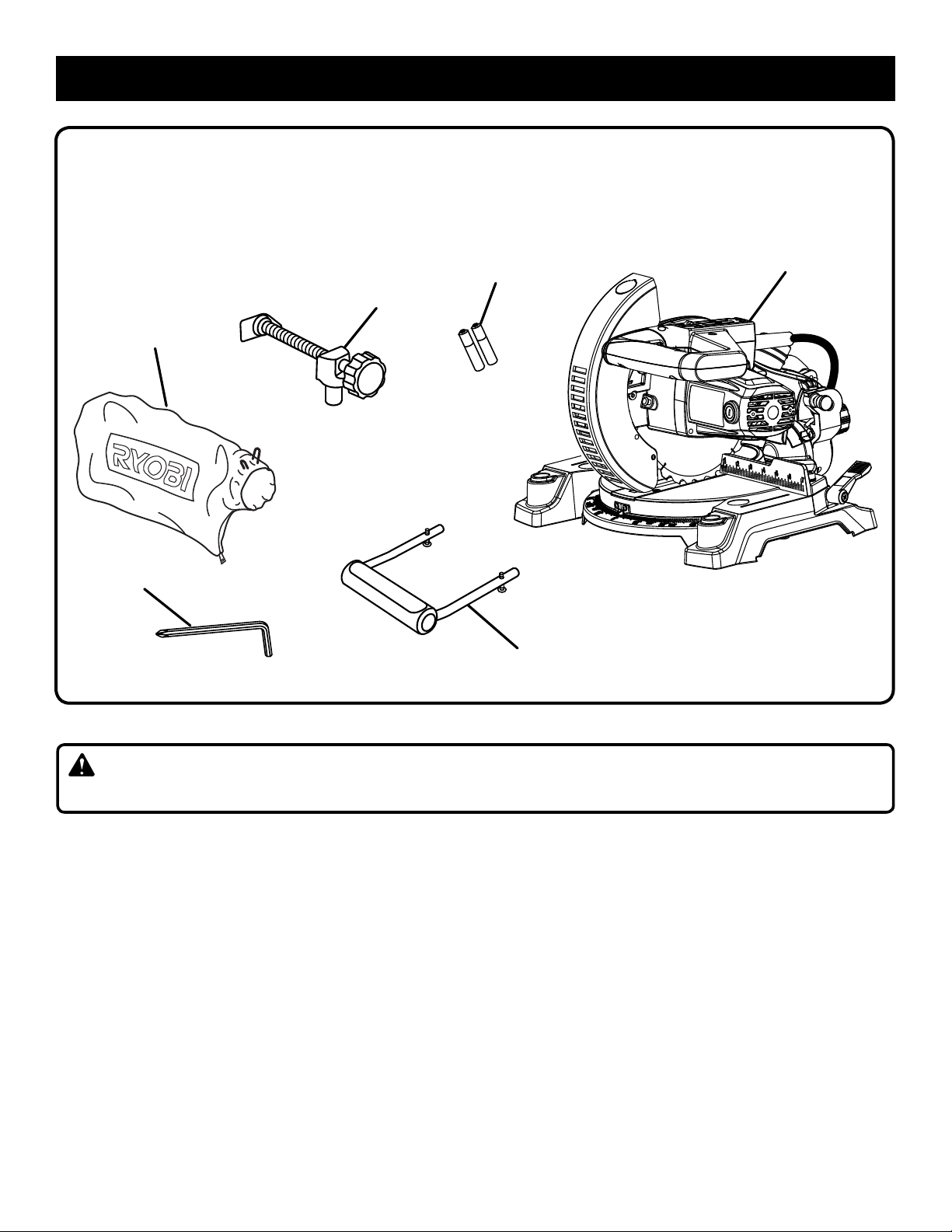
LOOSE PARTS LIST
The following items are included with your compound miter saw:
Miter Saw
Dust Bag
DUST
BAG
BLADE
WRENCH
Work Clamp
Blade Wrench
AAA Batteries (2)
WORK
CLAMP
BATTERIES
AAA
Rear Bracket/Carrying Handle
Operator’s Manual
MITER SAW
REAR BRACKET/
CARRYING HANDLE
WARNING:
The use of attachments or accessories not listed might be hazardous and could cause serious personal injury.
Fig. 7
11
Page 12
ASSEMBLY
UNPACKING
This product requires assembly.
Carefully lift miter saw from the carton by the “D” handle
and the saw base, and place it on a level work surface.
WARNING:
Do not use this product if any parts on the Loose Parts List
are already assembled to your product when you unpack
it. Parts on this list are not assembled to the product by
the manufacturer and require customer installation. Use
of a product that may have been improperly assembled
could result in serious personal injury.
The saw has been shipped with the saw arm secured in
the down position. To release the saw arm, push down
on the top of the saw arm, cut the tie-wrap, and pull out
on the lock pin.
Lift the saw arm by the handle. Hand pressure should
remain on the saw arm to prevent sudden rise upon
release of the tie wrap.
Inspect the tool carefully to make sure no breakage or
damage occurred during shipping.
Do not discard the packing material until you have care-
fully inspected and satisfactorily operated the tool.
The saw is factory set for accurate cutting. After
assembling it, check for accuracy. If shipping has
influenced the settings, refer to specific procedures
explained later in this manual.
If any parts are damaged or missing, please call
1-800-525-2579 for assistance.
WARNING:
If any parts are damaged or missing do not operate this
product until the parts are replaced. Use of this product
with damaged or missing parts could result in serious
personal injury.
WARNING:
Do not attempt to modify this tool or create accessories
not recommended for use with this tool. Any such alteration or modification is misuse and could result in a hazardous condition leading to possible serious personal injury.
WARNING:
Do not start the compound miter saw without checking
for interference between the blade and the miter fence.
Damage could result to the blade if it strikes the miter
fence during operation of the saw and may result in
personal injury.
WARNING:
Always make sure the compound miter saw is securely
mounted to a workbench or an approved workstand.
Failure to heed this warning can result in serious personal
injury.
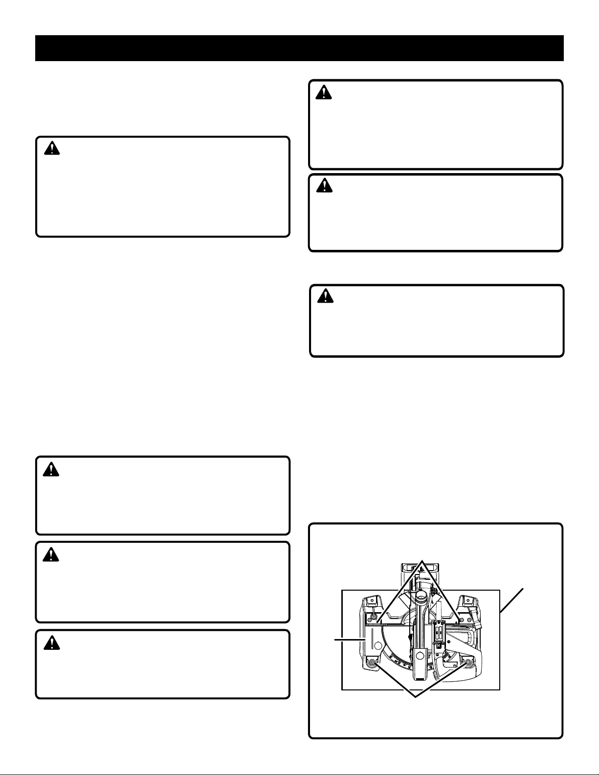
MOUNTING HOLES
See Figure 8.
WARNING:
Always make sure the compound miter saw is securely
mounted to a workbench or an approved workstand.
Failure to heed this warning can result in serious
personal injury.
If not using a stand, the saw should be mounted to a firm
supporting surface such as a workbench. Four bolt holes have
been provided in the saw base for this purpose. Each of the
four mounting holes should be bolted securely using 1/4 in.
machine bolts, lock washers, and hex nuts (not included).
Bolts should be of sufficient length to accommodate the
saw base, lock washers, hex nuts, and the thickness of the
workbench. Tighten all four bolts securely.
The hole pattern for mounting to a workbench is shown in
figure 8. Carefully check the workbench after mounting to
make sure that no movement can occur during use. If any
tipping, sliding, or walking is noted, secure the workbench
to the floor before operating.
TRACE HOLES
AT THESE LOCATIONS
FOR HOLE PATTERN
MOUNTING
SURFACE
WARNING:
Do not connect to power supply until assembly is
complete. Failure to comply could result in accidental
starting and possible serious personal injury.
12
BASE
TRACE HOLES
AT THESE LOCATIONS
FOR HOLE PATTERN
Fig. 8
Page 13
ASSEMBLY
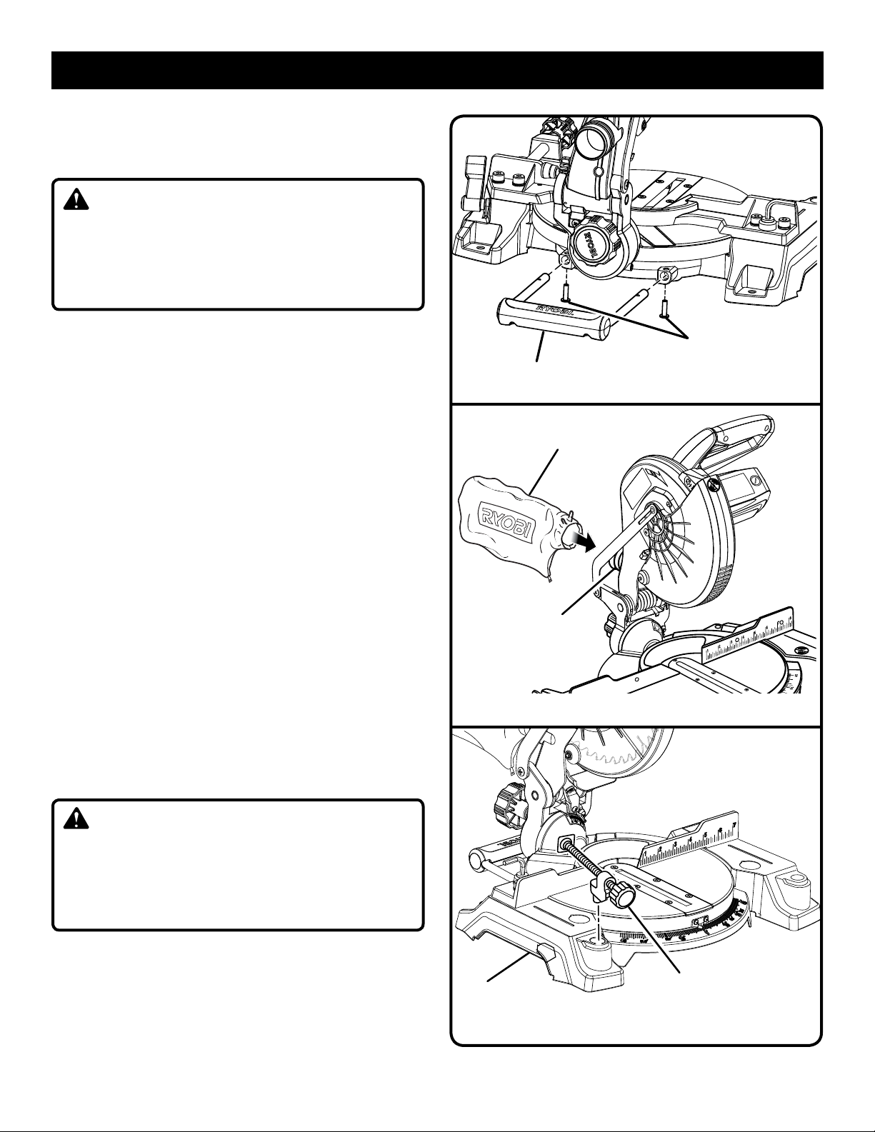
INSTALLING THE REAR BRACKET/CARRYING
HANDLE
See Figure 9.
CAUTION:
A rear bracket is included with this miter saw to prevent
tipping if the saw arm is released suddenly. Do not use
this saw before installing the rear bracket/carrying handle
and securely mounting the saw to a work surface or stand
and may result in personal injury.
Remove the screws from the rear bracket/carrying handle
and set aside.
Slide the bracket in the openings on the saw base, align-
ing the holes underneath the base with the holes in the
bracket.
Insert the screws into the holes and tighten securely.
DUST BAG
See Figure 10.
A dust bag is provided for use on the miter saw. It fits over
the exhaust port on the upper blade guard. Squeeze the two
metal clips to open the mouth of the bag and slide it on the
exhaust port. Release the clips. The metal ring in the bag
should lock in between the grooves on the exhaust port.
To remove the dust bag for emptying, simply reverse the
above procedure.
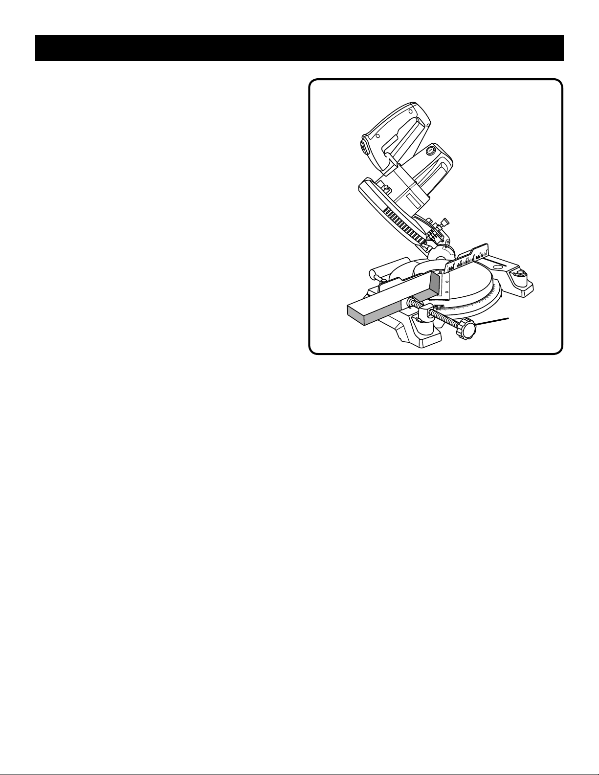
WORK CLAMP
See Figure 11.
The work clamp provides greater control by clamping the
workpiece to the fence. It also prevents the workpiece from
creeping toward the saw blade. This is very helpful when
cutting compound miters.
Depending on the cutting operation and the size of the
workpiece, it may be necessary to use a C-clamp instead
of the work clamp to secure the workpiece to the miter table
prior to making the cut.
REAR BRACKET/
CARRYING HANDLE
DUST
BAG
EXHAUST
PORT
SCREWS
Fig. 9
31.6
Fig. 10
WARNING:
In some operations, the work clamp assembly may
interfere with the operation of the blade guard assembly.
Always make sure there is no interference with the blade
guard prior to beginning any cutting operation to reduce
the risk of serious personal injury.
To install the work clamp:
Place the shaft of the work clamp in either hole on the
miter table base.
Rotate the knob on the work clamp clockwise to move it
in or counterclockwise to move it out as needed.
13
BASE
WORK
CLAMP
Fig. 11
Page 14
ASSEMBLY
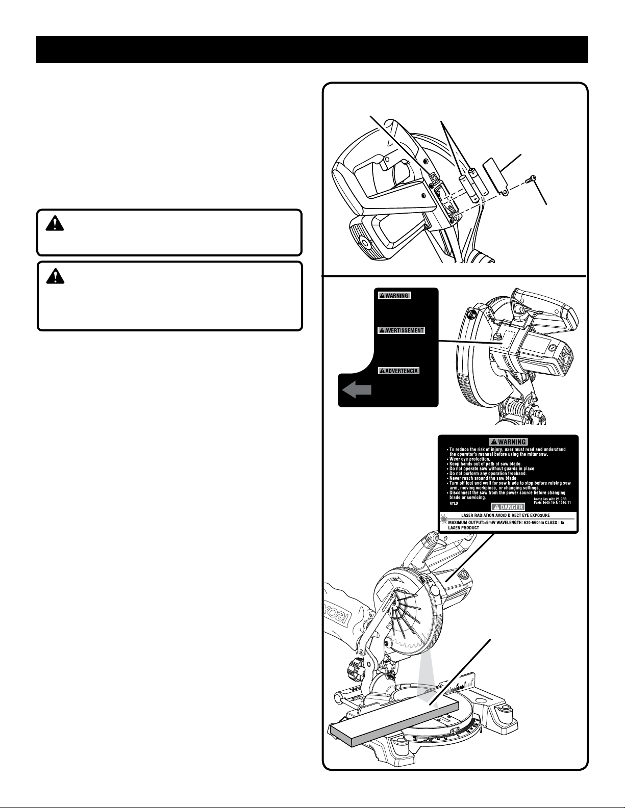
INSTALLING BATTERIES FOR LASER
See Figure 12.
Remove screw from battery compartment cover using
the Phillips end of the supplied blade wrench. Remove
cover and set aside.
Install two AAA batteries according to polarity indicators
inside the battery compartment.
Replace the battery compartment cover. Reinstall screw
and tighten securely.
DANGER:
Laser radiation. Avoid direct eye contact with light source.
WARNING:
Use of controls, adjustments, or performance of procedures other than those specified here can result in
hazardous radiation exposure.
ALIGNING THE LASER GUIDE LINE
See Figure 13.
Unplug the saw. Using a square, draw a straight line on the
workpiece. When the laser guide switch is turned on it will
generate a red line on the work surface. This line will let you
see your mark and the laser guide line at the same time,
and will assist you in lining up the mark for more accurate
cutting of the workpiece.
NOTE: The broken line may begin slightly skewed off of the
mark in the uppermost position. As the saw blade assembly
is lowered, at the approximate point the lower blade guard
starts to move, the laser line will be aligned with the mark and
remain aligned throughout the cut. This is normal. NEVER
attempt to move the workpiece while making a cut. Always
keep hands outside the “No Hands Zone”.
Once both lines are in alignment, do not move the workpiece.
Plug the saw into the power source. Make several practice
cuts on different styles and thickness of material. Repeat
the steps above as necessary.
Removing Your Mark:
Position the laser line near the left edge of your mark on the
work surface in order to remove the mark.
To Cut Your Mark:
Position the laser line near or over your mark on the work
surface in order to cut the mark.
To Leave Your Mark:
Position the laser line near the right edge of your mark on
the work surface in order to leave the mark.
After you have become familiar with using the laser guide,
you will be able to remove, cut, or leave your mark on the
work surface. Practice will teach you the correct position for
aligning the laser line with your mark.
LASER GUIDE
SWITCH
Lock
trigger prior to adjusting
laser. AVOID EXPOSURE:
Laser radiation emitted
from this aperture.
Fixer gâchette avant
laser est réglagé.
EVITER L’EXPOSITION :
Rayonnement laser
émise de cet orifice.
Asegure gatillo antes de
ajuste de laser. EVITE LA
EXPOSIOCIÔN: Radiactiôn
laser se emite por esta
abertura.
BATTERIES
COMPARTMENT
COVER
SCREW
Fig. 12
LASER
LINE
Fig. 13
14
Page 15
ASSEMBLY
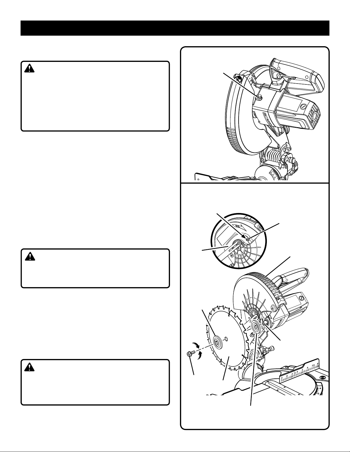
TO INSTALL/REPLACE THE BLADE
See Figures 14 - 15.
WARNING:
A 7-1/4 in. blade is the maximum blade capacity of the
saw. Never use a blade that is too thick to allow outer
blade washer to engage with the flats on the spindle.
Larger blades will come in contact with the blade guards,
while thicker blades will prevent the blade bolt from securing the blade on the spindle. Either of these situations
could result in a serious accident and can cause serious
personal injury.
Unplug the saw.
Raise the saw arm.
Rotate lower blade guard up and remove blade bolt cover
screw. Rotate blade bolt cover up and back to expose
the blade bolt.
Depress and hold the spindle lock button and rotate the
blade bolt until the spindle locks.
Using the wrench provided, loosen and remove the blade
bolt.
NOTE: The blade bolt has left hand threads. Turn blade
bolt clockwise to loosen.
Remove outer blade washer. Do not remove inner blade
washer.
Wipe a drop of oil onto inner blade washer and outer
blade washer where they contact the blade.
WARNING:
If inner blade washer has been removed, replace it before
placing blade on spindle. Failure to do so could cause an
accident since blade will not tighten properly.
Fit saw blade inside lower blade guard and onto spindle.
The blade teeth point downward at the front of saw as
shown in figure 15.
Replace outer blade washer. Double “D” flats on blade
washers align with flats on spindle.
Depress and hold spindle lock button and replace blade
bolt.
NOTE: The blade bolt has left hand threads. Turn blade bolt
counterclockwise to tighten.
CAUTION:
Always install the blade with the blade teeth and the
arrow printed on the side of the blade pointing down at
the front of the saw. The direction of blade rotation is
also stamped with an arrow on the upper blade guard.
SPINDLE
LOCK BUTTON
NOTE: BEFORE USE,
REPLACE SCREW AND
TIGHTEN SECURELY
TO PREVENT GUARD
MOVEMENT
BLADE
BOLT
COVER
OUTER BLADE
WASHER WITH
DOUBLE “D”
FLATS
TO
LOOSEN
TO
TIGHTEN
BLADE
BOLT
BLADE
Fig. 14
BLADE BOLT COVER
SCREW
LOWER
BLADE GUARD
FLAT(S)
ON SPINDLE
31.6
Tighten blade bolt securely.
Replace the lower blade guard and blade bolt cover.
Replace blade bolt cover screw and tighten securely.
INNER BLADE WASHER WITH
DOUBLE “D” FLATS
Fig. 15
15
Page 16
ASSEMBLY
WARNING:
Make sure the spindle lock button is not engaged
before reconnecting saw into power source. Never engage
spindle lock button when blade is rotating.
NOTE: Many of the illustrations in this manual show only
portions of the compound miter saw. This is intentional so
that we can clearly show points being made in the illustrations. Never operate the saw without all guards securely
in place and in good operating condition.
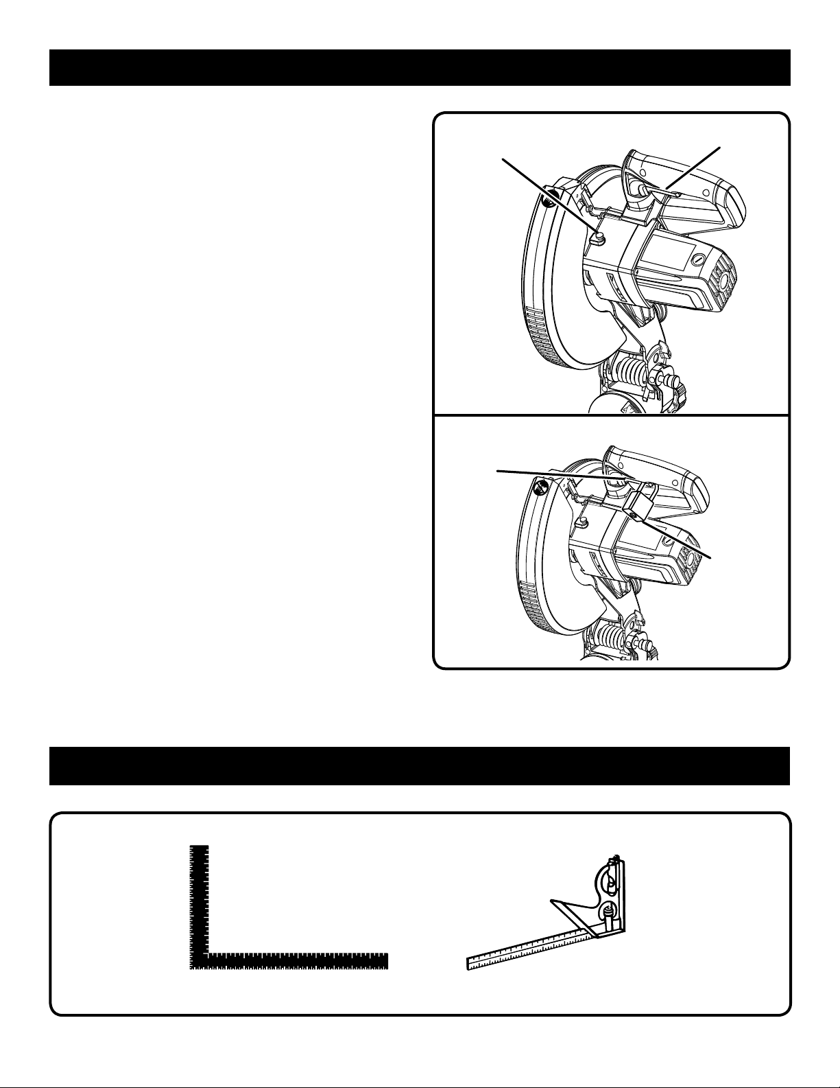
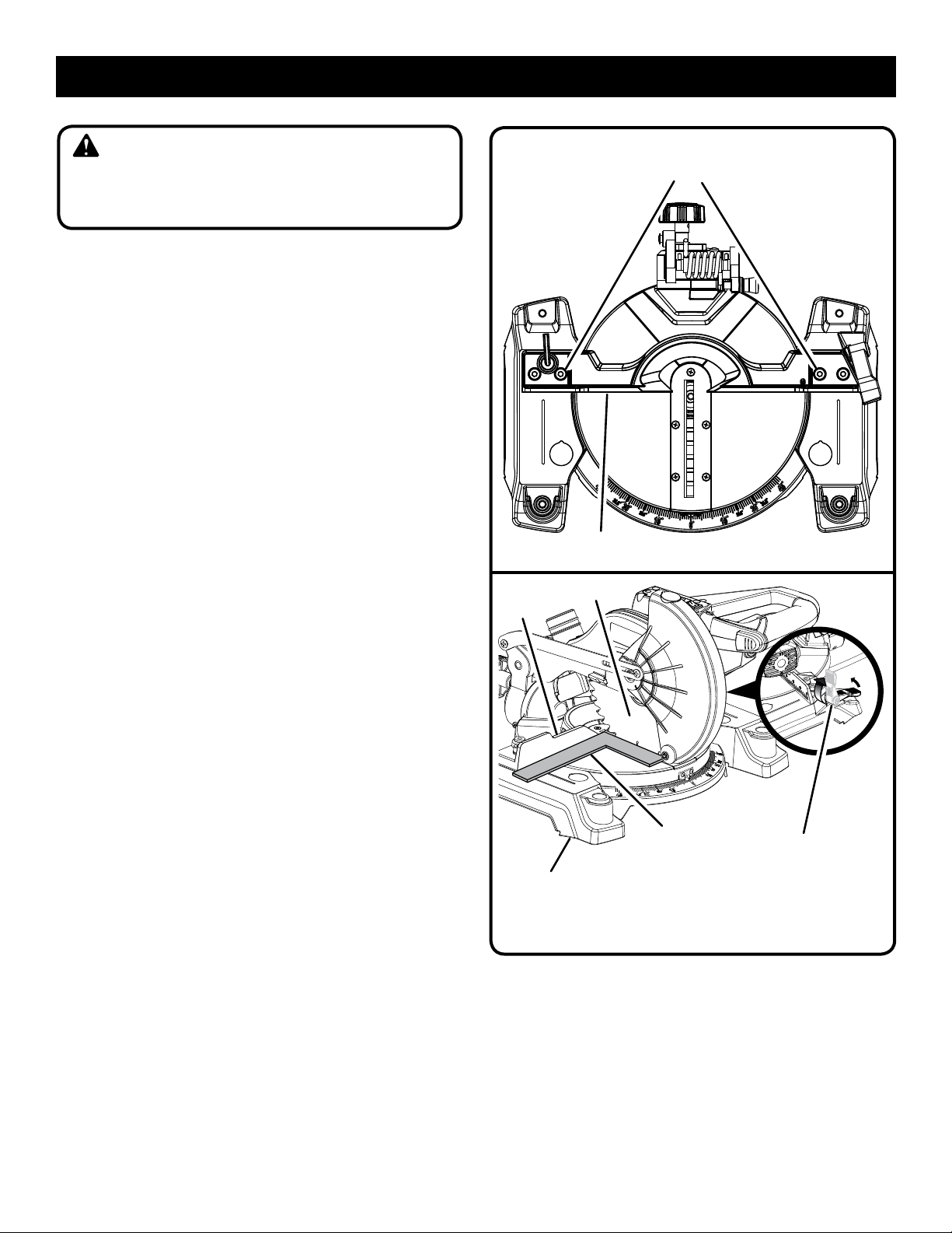
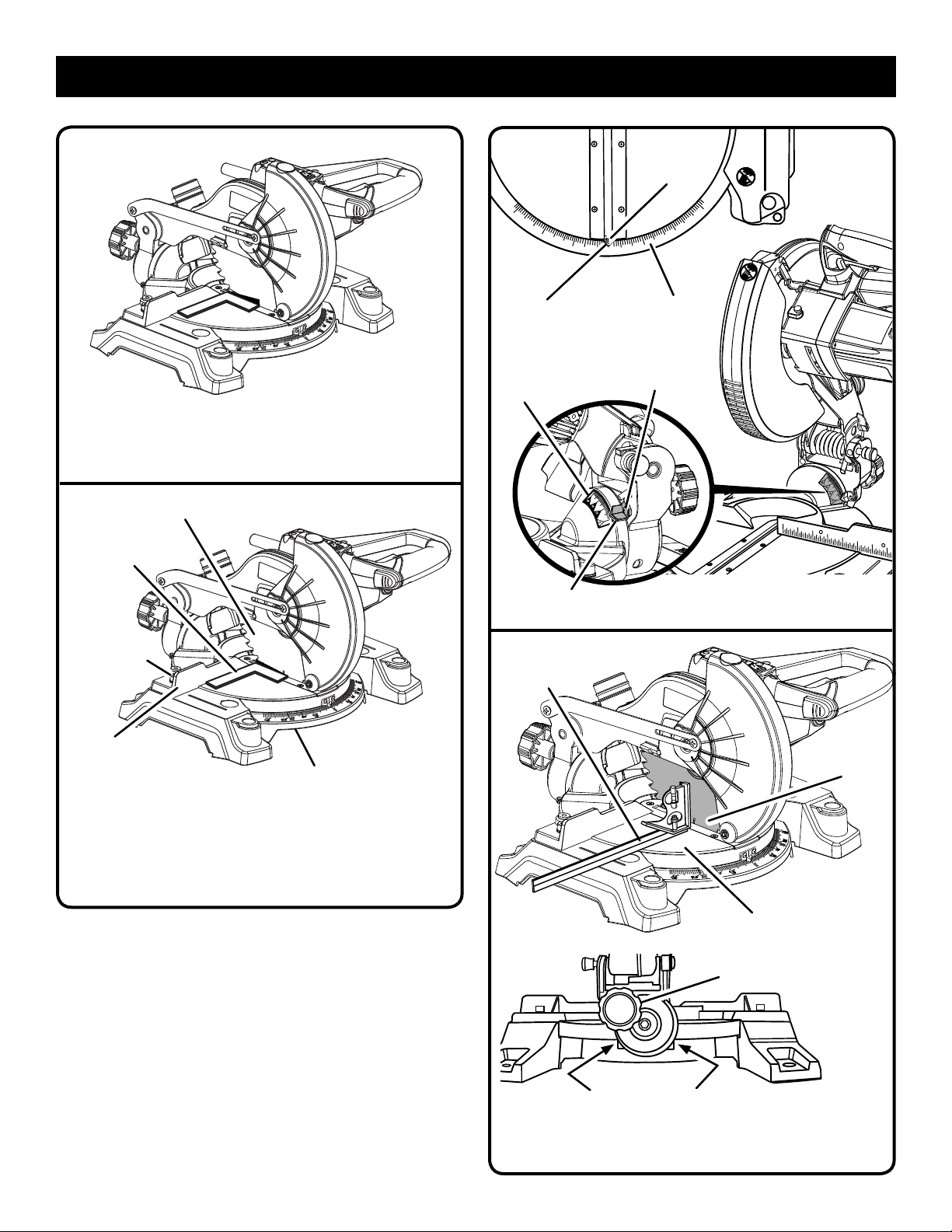
SQUARING THE BLADE TO THE FENCE
See Figures 16 - 19.
Unplug the saw.
Pull the saw arm all the way down and engage the lock
pin to hold the saw arm in transport position.
Unlock the miter lock lever.
Rotate the miter table until the pointer aligns with zero
dentent on the miter scale.
Lock the miter table.
Lay a square flat on the miter table. Place one leg of the
square against the fence. Slide the other leg of the square
against the flat part of saw blade.
NOTE: Make sure that the square contacts the flat part
of the saw blade, not the blade teeth.
The edge of the square and the saw blade should be
parallel as shown in figure 17.
If the front or back edge of the saw blade angles away
from the square as shown in figures 18-19, adjustments
are needed.
Using the blade wrench, loosen the socket head
screws that secure the miter fence to the miter table.
Rotate the miter fence left or right until the saw blade is
parallel with the square.
Retighten the screws securely and recheck the blade-to-
fence alignment.
The saw has two scale indicators, one on the bevel scale
and one on the miter scale. After squaring adjustments have
been made, it may be necessary to loosen the indicator
screws and reset them to zero. See figure 20.
MITER
FENCE
MITER
TABLE
SOCKET HEAD
SCREW(S)
FENCE
BLADE
SQUARE
VIEW OF BLADE SQUARE WITH FENCE
MITER
LOCK HANDLE
Fig. 16
Fig. 17
16
Page 17
ASSEMBLY
INDICATOR
SCREW
VIEW OF BLADE NOT SQUARE WITH FENCE,
SQUARE
SOCKET HEAD
SCREW(S)
MITER
FENCE
ADJUSTMENTS ARE REQUIRED
BLADE
MITER
TABLE
Fig. 18
SCALE
INDICATOR
BEVEL
SCALE
SCALE
INDICATOR
COMBINATION
SQUARE
MITER
SCALE
INDICATOR
SCREW
Fig. 20
BLADE
VIEW OF BLADE NOT SQUARE WITH FENCE,
ADJUSTMENTS ARE REQUIRED
Fig. 19
17
POSITIVE STOP
ADJUSTMENT SCREWS
CORRECT VIEW OF BLADE
SQUARE WITH MITER TABLE
MITER
TABLE
BEVEL
LOCK KNOB
Fig. 21
Page 18
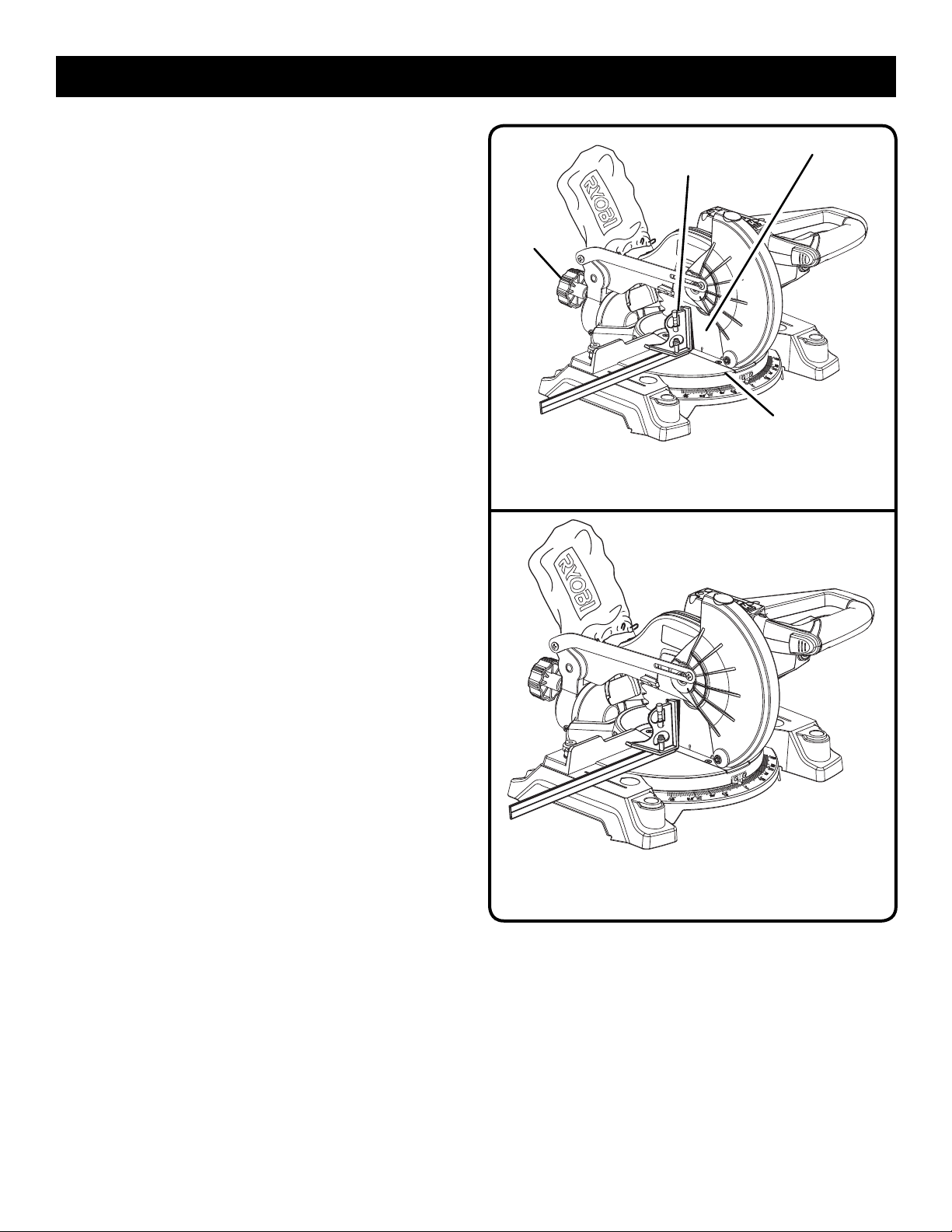
ASSEMBLY
SQUARING THE BLADE TO THE MITER TABLE
See Figures 19 - 23.
Unplug the saw.
Pull the saw arm all the way down and engage the lock
pin to hold the saw arm in transport position.
Unlock the miter lock lever.
Rotate the miter table until the pointer aligns with zero
detent on the miter scale.
Lock the miter lock.
Loosen bevel lock knob and set saw arm at 0
set 90° to miter table). Tighten bevel lock knob at stop.
Place a square against the miter table and the flat part
of saw blade.
NOTE: Make sure that the square contacts the flat part
of the saw blade, not the blade teeth.
Rotate the blade by hand and check the blade-to-table
alignment at several points.
The edge of the square and the saw blade should be
parallel as shown in figure 21.
If the top or bottom of the saw blade angles away from
the square as shown in figures 22 and 23, adjustments
are needed.
Loosen the bevel lock knob.
Adjust positive stop adjustment screw to bring saw blade
into alignment with the square. See Positive Stop Adjustment in the Adjustments section.
Retighten bevel lock knob. Recheck blade-to-table align-
ment.
NOTE: The above procedure can be used to check blade
squareness of the saw blade to the miter table at both 0
and 45° angles.
The saw has two scale indicators, one on the bevel scale
and one on the miter scale. After squaring adjustments have
been made, it may be necessary to loosen the indicator
screws and reset them to zero. See figure 20.
°
bevel (blade
°
BEVEL
LOCK KNOB
VIEW OF BLADE NOT SQUARE WITH MITER
COMBINATION
SQUARE
TABLE, ADJUSTMENTS ARE REQUIRED
BLADE
MITER
TABLE
Fig. 22
18
VIEW OF BLADE NOT SQUARE WITH MITER TABLE,
ADJUSTMENTS ARE REQUIRED
Fig. 23
Page 19
OPERATION
WARNING:
Do not allow familiarity with tools to make you careless.
Remember that a careless fraction of a second is sufficient
to inflict serious injury.
WARNING:
Always wear eye protection with side shields marked to
comply with ANSI Z87.1. Failure to do so could result in
objects being thrown into your eyes, resulting in possible
serious injury.
CUTTING WITH YOUR COMPOUND
MITER SAW
WARNING:
When using a work clamp or C-clamp to secure your
workpiece, clamp workpiece on one side of the blade
only. The workpiece must remain free on one side of the
blade to prevent the blade from binding in workpiece. The
workpiece binding the blade will cause motor stalling and
kickback. This situation could cause an accident resulting
in possible serious personal injury.
WARNING:
Do not use any attachments or accessories not recommended by the manufacturer of this tool. The use of attachments or accessories not recommended can result in
serious personal injury.
APPLICATIONS
This product has been designed only for the purposes listed
below:
Cross cutting wood, wood composition and plastic (do not
cut metals, ceramics, or masonry products.)
Cross cutting miters, joints, etc. for picture frames mold
ings, door casings, and fine joinery
Bevel cutting and compound cutting of lumber and moldings.
NOTE: The blade provided is fine for most wood cutting op
erations, but for fine joinery cuts or cutting plastic, use one of
the accessory blades available from the dealer.
WARNING:
Before starting any cutting operation, clamp or bolt the
compound miter saw to a workbench or an approved
workstand. Never operate the miter saw on the floor or in
a crouched position. Failure to heed this warning can result
in serious personal injury.
WARNING:
To avoid serious personal injury, always lock the miter lock
lever before making a cut. Failure to do so could result in
movement of the control arm or miter table while making
a cut.
WARNING:
To avoid serious personal injury, keep hands outside the
no hands zone, at least 3 in. from the blade. Never perform
any cutting operation freehand (without holding workpiece
against the fence). The blade could grab the workpiece if
it slips or twists.
WARNING:
NEVER move the workpiece or make adjustment to any
cutting angle while the saw is running and the blade is
rotating. Any slip can result in contact with the blade
causing serious personal injury.
TO CROSS CUT
See Figures 24 - 25.
A cross cut is made by cutting across the grain of the
workpiece. A straight cross cut is made with the miter table
set at the 0° position. Miter cross cuts are made with the
-
miter table set at some angle other than zero.
Pull out the lock pin and lift saw arm to its full height.
Unlock the miter table.
-
Rotate the miter table until the pointer aligns with zero
on the miter scale.
NOTE: You can quickly locate 0°, 15°, 22-1/2°, 31.62°
and 45° left or right as you rotate the control arm. The
miter table will seat itself in one of the detent index points,
located in base.
Lock the miter table.
Place the workpiece flat on the miter table with one edge
securely against the fence. If the board is warped, place
the convex side against the fence. If the concave edge
of a board is placed against the fence, the board could
collapse on the blade at the end of the cut, jamming the
blade. See figure 31.
When cutting long pieces of lumber or molding, support
the opposite end of the stock with a roller stand or with
a work surface level with the saw table. See Figure 29.
Align cutting line on workpiece with edge of saw blade
or laser line.
Grasp the workpiece firmly with one hand and secure
it against the fence. Use the optional work clamp or a
C-clamp to secure the workpiece when possible.
19
Page 20
OPERATION
Before turning on the saw, perform a dry run of the cutting
operation just to make sure that no problems will occur
when the cut is made.
Grasp the saw handle firmly. Depress the switch lock
with thumb then squeeze the switch trigger. Allow several
seconds for the blade to reach maximum speed.
Slowly lower the blade into and through the workpiece.
Release the switch trigger and allow the blade to stop
rotating before raising the blade out of the workpiece.
Wait until the blade stops turning before removing the
workpiece from the miter table.
TO BEVEL CUT
See Figure 26.
A bevel cut is made by cutting across the grain of the workpiece
with the blade angled to the workpiece. A straight bevel cut
is made with the miter table set at the zero degree position
and the blade set at an angle between 0° and 45°.
Pull out the lock pin and lift saw arm to its full height.
Unlock the miter table.
Rotate the miter table until the pointer aligns with zero
on the miter scale.
NOTE: You can quickly locate 0°, 15°, 22-1/2°, 31.62°
and 45° left or right as you rotate the control arm. The
miter table will seat itself in one of the detent index points,
located in base.
Lock the miter table.
Loosen the bevel lock knob and move the saw arm to the
left to the desired bevel angle.
Bevel angles can be set from 0° to 45°.
Align the indicator point for the desired angle.
Once the saw arm has been set at the desired angle,
securely tighten the bevel lock knob.
Place the workpiece flat on the miter table with one edge
securely against the fence. If the board is warped, place
the convex side against the fence. If the concave edge
of a board is placed against the fence, the board could
collapse on the blade at the end of the cut, jamming the
blade. See figure 31.
When cutting long pieces of lumber or molding, support
the opposite end of the stock with a roller stand or with
a work surface level with the saw table. See Figure 29.
Align the cutting line on the workpiece with the edge of
saw blade or laser line.
Grasp the workpiece firmly with one hand and secure
it against the fence. Use the optional work clamp or a
C-clamp to secure the workpiece when possible.
Before turning on the saw, perform a dry run of the cutting
operation just to make sure that no problems will occur
when the cut is made.
BEVEL
LOCK
KNOB
SWITCH
LOCK
BEVEL
SCALE
CROSS CUT
MITER CUT
BEVEL CUT
WORK
CLAMP
Fig. 24
Fig. 25
LOCK PIN
INDICATOR
POINT
20
Fig. 26
Page 21
OPERATION
Grasp the saw handle firmly. Depress the switch lock
with thumb then squeeze the switch trigger. Allow several
seconds for the blade to reach maximum speed.
Slowly lower the blade into and through the workpiece.
Release the switch trigger and allow the saw blade to stop
rotating before raising the blade out of the workpiece.
Wait until the blade stops turning before removing the
workpiece from miter table.
TO COMPOUND MITER CUT
See Figures 27 - 28.
A compound miter cut is a cut made using a miter angle and
a bevel angle at the same time. This type of cut is used to
make picture frames, cut molding, make boxes with sloping
sides, and for certain roof framing cuts.
To make this type of cut the control arm on the miter table
must be rotated to the correct angle and the saw arm must
be tilted to the correct bevel angle. Care should always
be taken when making compound miter setups due to the
interaction of the two angle settings.
Adjustments of miter and bevel settings are interdependent
with one another. Each time you adjust the miter setting you
change the effect of the bevel setting. Also, each time you
adjust the bevel setting you change the effect of the miter
setting.
It may take several settings to obtain the desired cut. The
first angle setting should be checked after setting the second
angle, since adjusting the second angle affects the first.
Once the two correct settings for a particular cut have been
obtained, always make a test cut in scrap material before
making a finish cut in good material.
Pull out the lock pin and lift saw arm to its full height.
Unlock the miter table.
Rotate the miter table until the pointer aligns with zero
on the miter scale.
NOTE: You can quickly locate 0°, 15°, 22-1/2°, 31.62°
and 45° left or right as you rotate the control arm. The
miter table will seat itself in one of the detent index points,
located in base.
Lock the miter table.
Loosen the bevel lock knob and move the saw arm to
the left to the desired bevel angle.
Bevel angles can be set from 0° to 45°.
Once the saw arm has been set at the desired angle,
securely tighten the bevel lock knob.
Recheck miter angle setting. Make a test cut in scrap
material.
COMPOUND MITER CUT
WORK
CLAMP
Fig. 27
21
Page 22
OPERATION
Place the workpiece flat on the miter table with one edge
securely against the fence. If the board is warped, place
the convex side against the fence. If the concave edge
of a board is placed against the fence, the board could
collapse on the blade at the end of the cut, jamming the
blade. See figure 31.
When cutting long pieces of lumber or molding, support
the opposite end of the stock with a roller stand or with
a work surface level with the saw table. See Figure 29.
Align the cutting line on the workpiece with the edge of
saw blade or laser line.
Grasp the stock firmly with one hand and secure it against
the fence. Use the optional work clamp or a C-clamp to
secure the workpiece when possible. See Figure 28.
Before turning on the saw, perform a dry run of the cutting
operation just to make sure that no problems will occur
when the cut is made.
Grasp the saw handle firmly. Depress the switch lock
with thumb then squeeze the switch trigger. Allow several
seconds for the blade to reach maximum speed.
Slowly lower the blade into and through the workpiece.
Release the switch trigger and allow the saw blade to stop
rotating before raising the blade out of the workpiece.
Wait until the blade stops turning before removing the
workpiece from miter table.
°
X 45° COMPOUND MITER CUT
45
Fig. 28
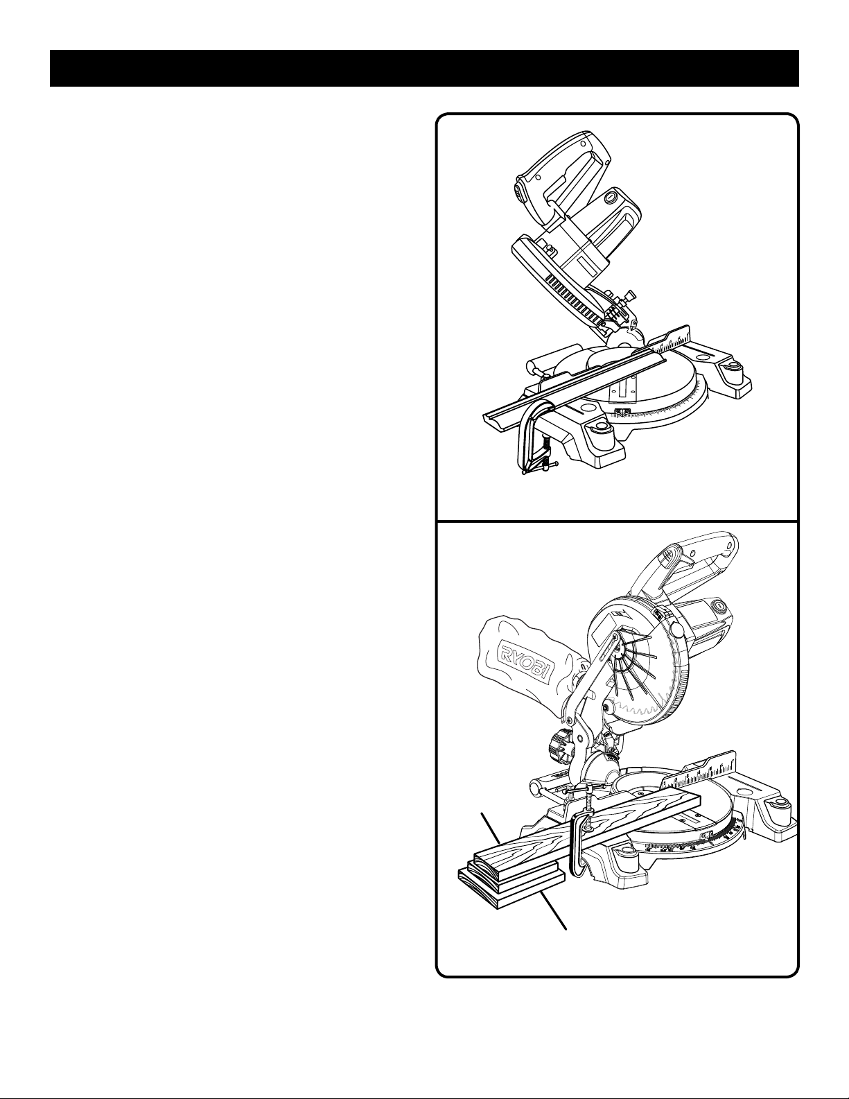
TO SUPPORT LONG WORKPIECES
See Figure 29.
Long workpieces need extra supports. Supports should be
placed along the workpiece so it does not sag. The support
should let the workpiece lay flat on the base of the saw and
worktable during the cutting operation. Use the optional work
clamp or a C-clamp to secure the workpiece.
LONG
WORKPIECE
0
WORKPIECE
SUPPORTS
Fig. 29
22
Page 23

OPERATION
CUTTING COMPOUND MITERS
To aid in making the correct settings, the compound angle setting chart below has been provided. Since compound cuts
are the most difficult to accurately obtain, trial cuts should be made in scrap material, and much thought and planning
made, prior to making the required cut.
PITCH
OF SIDE
0°
5°
10°
15°
20°
25°
30°
35°
40°
45°
50°
55°
60°
65°
70°
75°
80°
85°
90°
4
M- 45.00°
B- 0.00°
M- 44.89°
B- 3.53°
M- 44.56°
B- 7.05°
M- 44.01°
B- 10.55°
M- 43.22°
B- 14.00°
M- 42.19°
B- 17.39°
M- 40.89°
B- 20.70°
M- 39.32°
B- 23.93°
M- 37.45°
B- 27.03°
M- 35.26°
B- 30.00°
M- 32.73°
B- 32.80°
M- 29.84°
B- 35.40°
M- 26.57°
B- 37.76°
M- 22.91°
B- 39.86°
M- 18.88°
B- 41.64°
M- 14.51°
B- 43.08°
M- 9.85°
B- 44.14°
M- 4.98°
B- 44.78°
M- 0.00°
B- 45.00°
5
M- 36.00°
B- 0.00°
M- 35.90°
B- 2.94°
M- 35.58°
B- 5.86°
M- 35.06°
B- 8.75°
M- 34.32°
B- 11.60°
M- 33.36°
B- 14.38°
M- 32.18°
B- 17.09°
M- 30.76°
B- 19.70°
M- 29.10°
B- 22.20°
M- 27.19°
B- 24.56°
M- 25.03°
B- 26.76°
M- 22.62°
B- 28.78°
M- 19.96°
B- 30.60°
M- 17.07°
B- 32.19°
M- 13.95°
B- 33.53°
M- 10.65°
B- 34.59°
M- 7.19°
B- 35.37°
M- 3.62°
B- 35.84°
M- 0.00°
B- 36.00°
NUMBER OF SIDES
6
M- 30.00°
B- 0.00°
M- 29.91°
B- 2.50°
M- 29.62°
B- 4.98°
M- 29.15°
B- 7.44°
M- 28.48°
B- 9.85°
M- 27.62°
B- 12.20°
M- 26.57°
B- 14.48°
M- 25.31°
B- 16.67°
M- 23.86°
B- 18.75°
M- 22.21°
B- 20.70°
M- 20.36°
B- 22.52°
M- 18.32°
B- 24.18°
M- 16.10°
B- 25.66°
M- 13.71°
B- 26.95°
M- 11.17°
B- 28.02°
M- 8.50°
B- 28.88°
M- 5.73°
B- 29.50°
M- 2.88°
B- 29.87°
M- 0.00°
B- 30.00°
7
M- 25.71°
B- 0.00°
M- 25.63°
B- 2.17°
M- 25.37°
B- 4.32°
M- 24.95°
B- 6.45°
M- 24.35°
B- 8.53°
M- 23.56°
B- 10.57°
M- 22.64°
B- 12.53°
M- 21.53°
B- 14.41°
M- 20.25°
B- 16.19°
M- 18.80°
B- 17.87°
M- 17.20°
B- 19.41°
M- 15.44°
B- 20.82°
M- 13.54°
B- 22.07°
M- 11.50°
B- 23.16°
M- 9.35°
B- 24.06°
M- 7.10°
B- 24.78°
M- 4.78°
B- 25.30°
M- 2.40°
B- 25.61°
M- 0.00°
B- 25.71°
8 9
M- 22.50°
B- 0.00°
M- 22.42°
B- 1.91°
M- 22.19°
B- 3.81°
M- 21.81°
B- 5.68°
M- 21.27°
B- 7.52°
M- 20.58°
B- 9.31°
M- 19.73°
B- 11.03°
M- 18.74°
B- 12.68°
M- 17.60°
B- 14.24°
M- 16.32°
B- 15.70°
M- 14.91°
B- 17.05°
M- 13.36°
B- 18.27°
M- 11.70°
B- 19.35°
M- 9.93°
B- 20.29°
M- 8.06°
B- 21.08°
M- 6.12°
B- 21.69°
M- 4.11°
B- 22.14°
M- 2.07°
B- 22.41°
M- 0.00°
B- 22.50°
M- 20.00°
B- 0.00°
M- 19.93°
B- 1.71°
M- 19.72°
B- 3.40°
M- 19.37°
B- 5.08°
M- 18.88°
B- 6.72°
M- 18.26°
B- 8.31°
M- 17.50°
B- 9.85°
M- 16.60°
B- 11.31°
M- 15.58°
B- 12.70°
M- 14.43°
B- 14.00°
M- 13.17°
B- 15.19°
M- 11.79°
B- 16.27°
M- 10.31°
B- 17.23°
M- 8.74°
B- 18.06°
M- 7.10°
B- 18.75°
M- 5.38°
B- 19.29°
M- 3.62°
B- 19.68°
M- 1.82°
B- 19.92°
M- 0.00°
B- 20.00°
10
M- 18.00°
B- 0.00°
M- 17.94°
B- 1.54°
M- 17.74°
B- 3.08°
M- 17.42°
B- 4.59°
M- 16.98°
B- 6.07°
M- 16.41°
B- 7.50°
M- 15.72°
B- 8.89°
M- 14.90°
B- 10.21°
M- 13.98°
B- 11.46°
M- 12.94°
B- 12.62°
M- 11.80°
B- 13.69°
M- 10.56°
B- 14.66°
M- 9.23°
B- 15.52°
M- 7.82°
B -16.26°
M- 6.34°
B- 16.88°
M- 4.81°
B- 17.37°
M- 3.23°
B- 17.72°
M- 1.62°
B- 17.93°
M- 0.00°
B- 18.00°
Each B (Bevel) and M (Miter) Setting is Given to the Closest 0.005°.
COMPOUND-ANGLE SETTINGS FOR POPULAR STRUCTURES
23
Page 24
OPERATION
CUTTING CROWN MOLDING
This compound miter saw does an excellent job of cutting
crown molding. In general, compound miter saws do a better
job of cutting crown molding than any other tool made.
In order to fit properly, crown molding must be compound
mitered with extreme accuracy.
The two contact surfaces on a piece of crown molding that
fit flat against the ceiling and the wall of a room are at angles
that, when added together, equal exactly 90°. Most crown
molding has a top rear angle (the section that fits flat against
the ceiling) of 52° and a bottom rear angle (the section that
fits flat against the wall) of 38°.
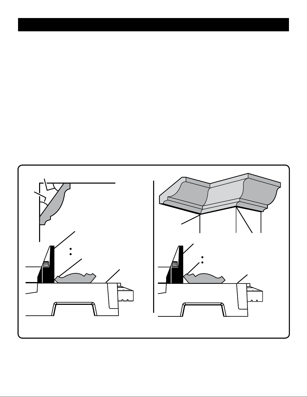
LAYING MOLDING FLAT ON THE MITER
TABLE
See Figure 30.
To use this method for accurately cutting crown molding for
a 90° inside or outside corner, lay the molding with its broad
back surface flat on the miter table and against the fence.
°
52
CEILING
When setting the bevel and miter angles for compound miters,
remember that the settings are interdependent; changing
one angle changes the other angle as well.
Keep in mind that the angles for crown molding are very
precise and difficult to set. Since it is very easy for these
angles to shift, all settings should first be tested on scrap
molding. Also most walls do not have angles of exactly 90°,
therefore, you will need to fine tune your settings.
When cutting crown molding by this method the bevel angle
should be set at 33.85°. The miter angle should be set at
31.62° either right or left, depending on the desired cut for
the application. See the chart for correct angle settings and
correct positioning of crown molding on miter table.
The settings in the chart can be used for cutting. All Standard
(U.S.) crown molding with 52° and 38° angles. The crown
molding is placed flat on the miter table using the compound
features of the miter saw.
38
W
A
L
L
°
FENCE
TOP EDGE AGAINST FENCE =
LEFT SIDE, INSIDE CORNER
RIGHT SIDE, OUTSIDE CORNER
MITER TABLE
CROWN MOLDING FLAT ON MITER TABLE
INSIDE
CORNER
FENCE
BOTTOM EDGE AGAINST FENCE =
RIGHT SIDE, INSIDE CORNER
LEFT SIDE, OUTSIDE CORNER
MITER TABLE
OUTSIDE
CORNER
Fig. 30
24
Page 25
Bevel
Angle Type of Cut
Setting
Left side, inside corner
33.85°
33.85°
33.85°
1. Top edge of molding against fence
2. Miter table set right 31.62°
3. Save left end of cut
Right side, inside corner
1. Bottom edge of molding against fence
2. Miter table set left 31.62°
3. Save left end of cut
Left side, outside corner
1. Bottom edge of molding against fence
2. Miter table set left 31.62°
3. Save right end of cut
OPERATION
Right side, outside corner
33.85°
1. Top edge of molding against fence
2. Miter table set right 31.62°
3. Save right end of cut
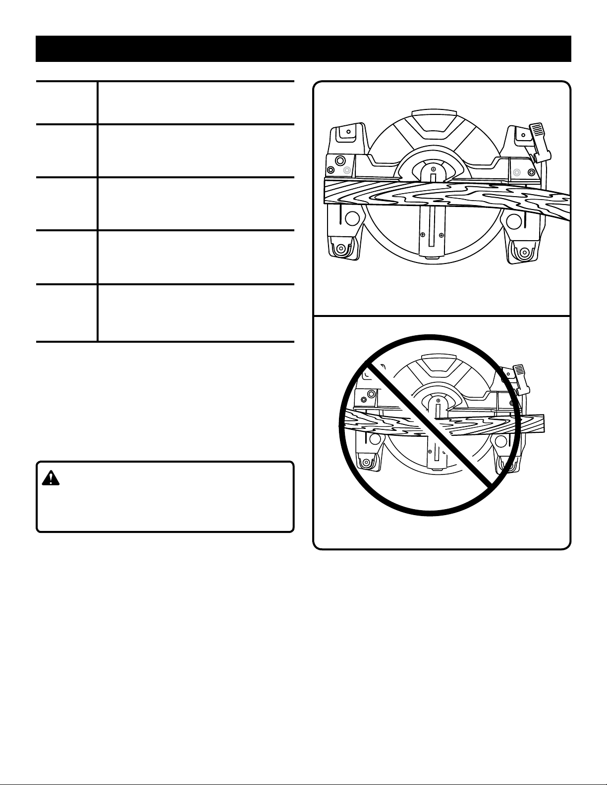
CUTTING WARPED MATERIAL
See Figures 31 - 32.
When cutting warped material, always make sure it is positioned on the miter table with the convex side against the
fence as shown in figure 31.
If the warped material is positioned the wrong way as shown
in figure 32, it will pinch the blade near the completion of
the cut.
WARNING:
To avoid a kickback and to avoid serious personal injury,
never position the concave edge of bowed or warped
material against the fence.
RIGHT
WRONG
Fig. 31
Fig. 32
25
Page 26
ADJUSTMENTS
WARNING:
Before performing any adjustment, make sure the tool is
unplugged from the power supply. Failure to heed this
warning could result in serious personal injury.
The compound miter saw has been adjusted at the
factory for making very accurate cuts. However, some of
the components might have been jarred out of alignment
during shipping. Also, over a period of time, readjustment
will probably become necessary due to wear. After unpacking
the saw, check the following adjustments before you begin
using the saw. Make any readjustments that are necessary
and periodically check the parts alignment to make sure that
the saw is cutting accurately.
CAUTION:
Do not start the compound miter saw without checking
for interference between the blade and the throat plate.
Damage may result to the blade if it strikes the throat
plate during operation of the saw and may result in personal injury.
POSITIVE STOP ADJUSTMENTS
See Figure 33.
NOTE: These adjustments were made at the factory and
normally do not require readjustment.
To adjust:
Unplug the saw.
Loosen the bevel lock knob by turning the knob
counterclockwise.
Square the blade to the miter table as described in the
Assembly section of this manual.
If the blade is out of square, adjust by tightening or
loosening the positive stop adjustment screw.
Retighten bevel lock knob. Recheck blade-to-table
alignment.
NOTE: The above procedure can be used to check blade
squareness of the saw blade to the miter table at both 0°
and 45° angles.
The saw has two scale indicators, one on the bevel scale
and one on the miter scale. After squaring adjustments have
been made, it may be necessary to loosen the indicator
screws and reset them to zero. See figure 20.
PIVOT ADJUSTMENTS
NOTE: These adjustments were made at the factory and
normally do not require readjustment.
TRAVEL PIVOT ADJUSTMENT
The saw arm should rise completely to the up position
by itself.
If the saw arm does not raise by itself or if there is play
in the pivot joints, have saw repaired by at your nearest
authorized service center.
BEVEL PIVOT ADJUSTMENT
The compound miter saw should bevel easily by loosening
the bevel lock knob and tilting the saw arm to the left.
If movement is tight or if there is play in the pivot, have saw
repaired by at your nearest authorized service center.
BEVEL LOCK
KNOB
POSITIVE STOP
ADJUSTMENT
SCREW FOR
0° ANGLES
POSITIVE STOP
ADJUSTMENT
SCREW FOR
45° ANGLES
Fig. 33
26
Page 27

ADJUSTMENTS
DANGER:
Laser radiation. Avoid direct eye contact with light
source.
WARNING:
Use of controls or adjustments or performance of procedures other than those specified herein can result in
hazardous radiation exposure.
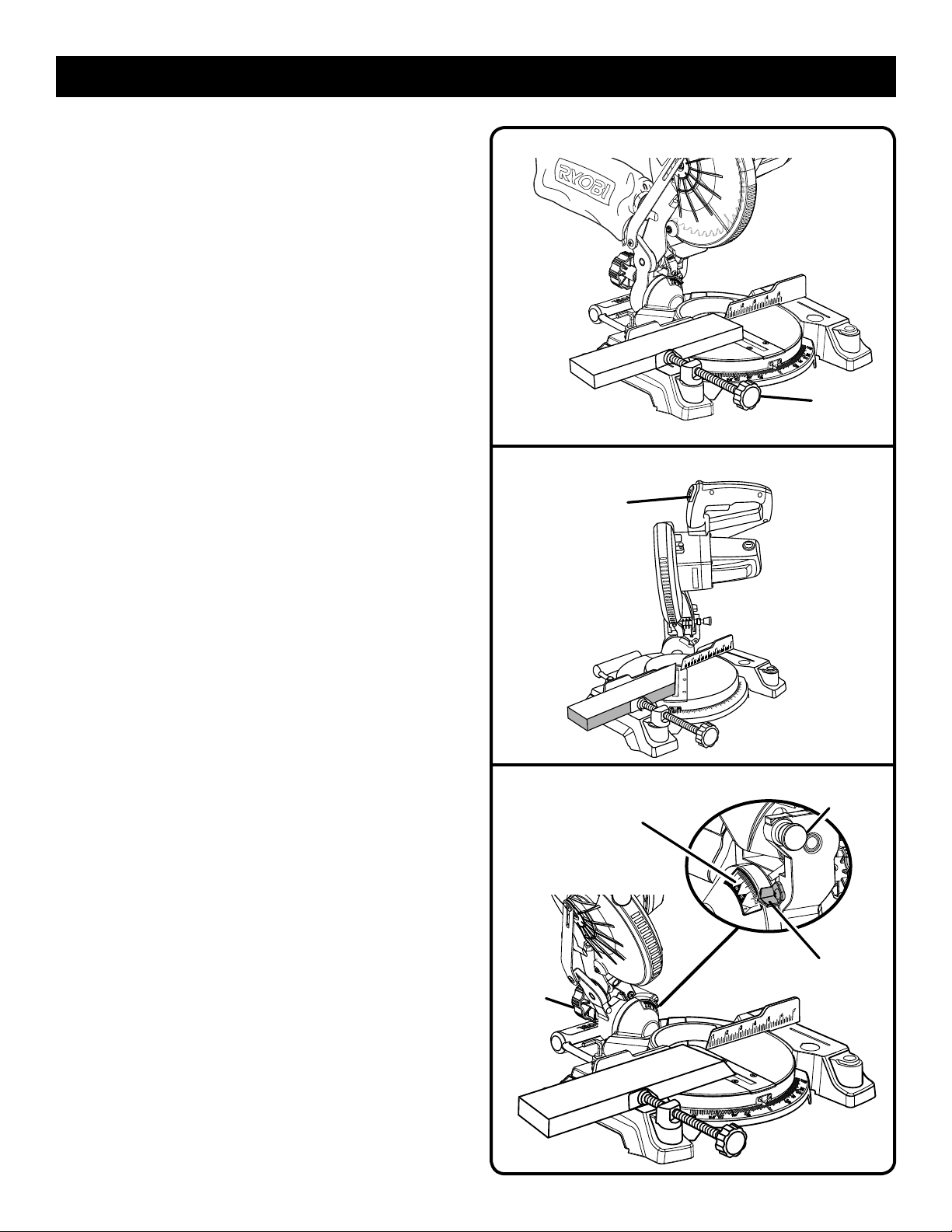
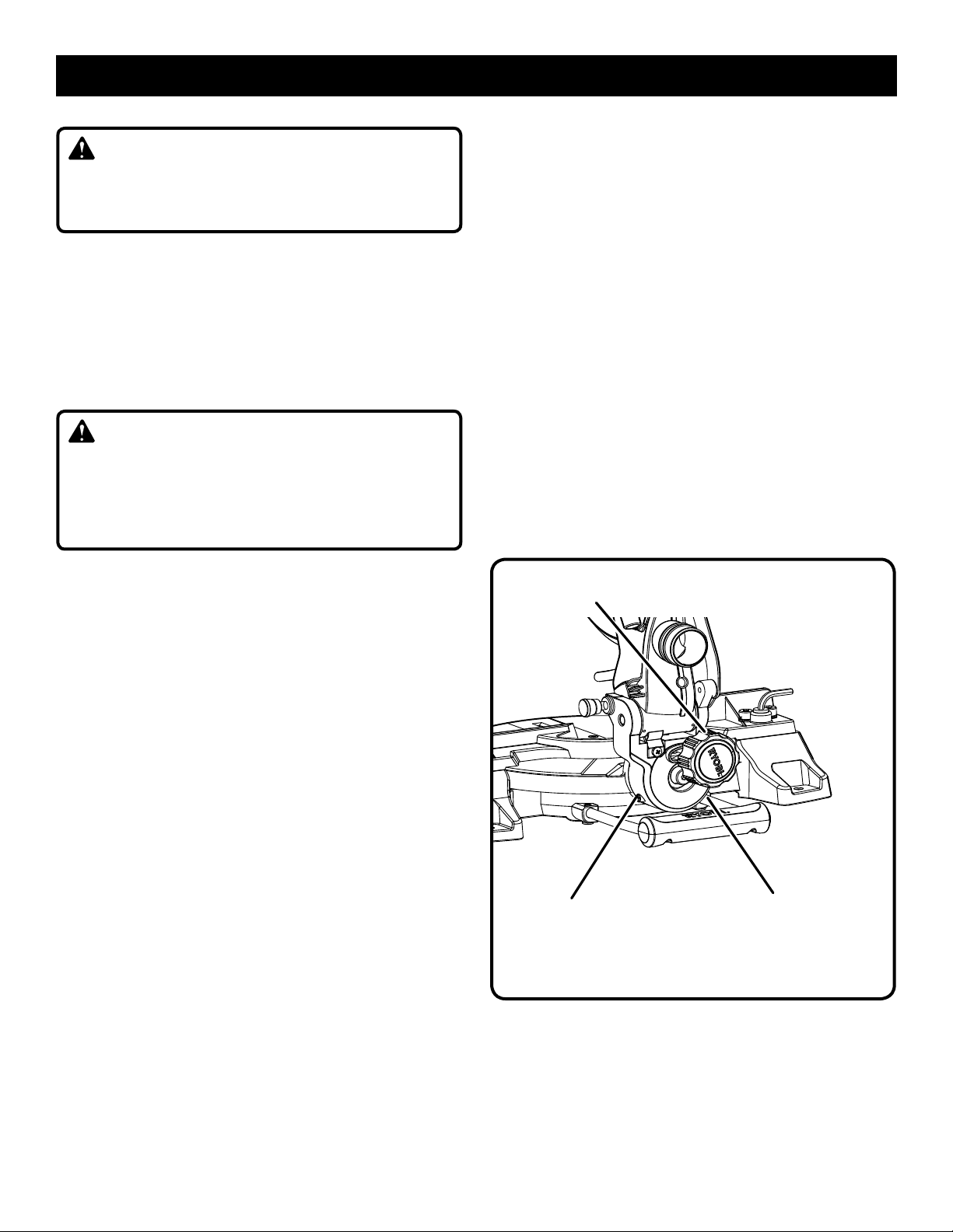
TO ADJUST THE LASER GUIDE
See Figure 34.
Use the work clamp or a C-clamp to secure a piece of
scrap wood.
Plug the saw into the power source and make a slight
cut to score the wood.
Release the switch trigger and allow the saw blade to
stop rotating before raising the blade.
Raise the saw arm.
Unplug the saw.
Turn the laser switch on.
NOTE: The broken line may begin slightly skewed off of
the mark in the uppermost position. As the saw blade
assembly is lowered, at the approximate point the lower
blade guard starts to move, the laser line will be aligned
with the mark and remain aligned throughout the cut. This
is normal. NEVER attempt to move the workpiece while
making a cut. Always keep hands outside the “No Hands
Zone”.
Using the Phillips end of the supplied blade wrench, turn
the laser adjustment screw counterclockwise to move the
laser line left or clockwise to move the laser line right.
NOTE: When properly aligned, the laser should be on the
left edge of the kerf.
LASER
ADJUSTMENT
SCREW
LASER
ASSEMBLY
Fig. 34
TO ADJUST THE MITER LOCK LEVER
See Figure 35.
Prior to squaring the saw blade to the fence, check and adjust
the miter lock lever, if needed. In the “locked” position, the
action of fully locking the miter lock lever should feel tight
and secure. Considerable effort should be required to move
the miter table. If the table moves easily when in the “locked”
position, an adjustment of the miter lock lever is required.
To adjust:
Unplug the saw.
Lock the miter lock lever completely.
Pull the miter lock lever out to the right to disengage, then
rotate forward to adjust.
Release miter lock lever to re-engage
Recheck the miter table to ensure proper tightness.
ADJUST
DESENGAGE
MITER
LOCK LEVER
Fig. 35
27
Page 28

MAINTENANCE
WARNING:
When servicing, use only identical replacement parts.
Use of any other parts can create a hazard or cause
product damage.
WARNING:
Always wear eye protection with side shields marked to
comply with ANSI Z87.1. Failure to do so could result in
objects being thrown into your eyes, resulting in possible
serious injury.
GENERAL MAINTENANCE
Avoid using solvents when cleaning plastic parts. Most
plastics are susceptible to damage from various types of
commercial solvents and may be damaged by their use. Use
clean cloths to remove dirt, dust, oil, grease, etc.
WARNING:
Do not at any time let brake fluids, gasoline, petroleumbased products, penetrating oils, etc., come in contact
with plastic parts. Chemicals can damage, weaken or
destroy plastic which can result in serious personal injury.
Electric tools used on fiberglass material, wallboard, spackling
compounds, or plaster are subject to accelerated wear and
possible premature failure because the fiberglass chips and
grindings are highly abrasive to bearings, brushes, commutators, etc. Consequently, we do not recommend using this
tool for extended work on these types of materials. However,
if you do work with any of these materials, it is extremely
important to clean the tool using compressed air.
LUBRICATION
All of the bearings in this tool are lubricated with a sufficient
amount of high grade lubricant for the life of the unit under
normal operating conditions. Therefore, no further lubrication is required.
BRUSH
CAP
BRUSH
ASSEMBLY
BRUSH
ASSEMBLY
BRUSH
CAP
Fig. 36
BRUSH REPLACEMENT
See Figure 36.
The saw has externally accessible brush assemblies that
should be periodically checked for wear.
Proceed as follows when replacement is required:
Unplug the saw.
Remove brush cap with a screwdriver. Brush assembly is
spring loaded and will pop out when you remove brush
cap.
Remove brush assembly.
Check for wear. Replace both brushes when either has
less than 1/4 in. length of carbon remaining. Do not
replace one side without replacing the other.
Reassemble using new brush assemblies. Make sure
curvature of brush matches curvature of motor and that
brush moves freely in brush tube.
Make sure brush cap is oriented correctly (straight) and
replace.
Tighten brush cap securely. Do not overtighten.
This product has a Three-year Limited Warranty.
For Warranty details go to www.ryobitools.com
28
Page 29

RÈGLES DE SÉCURITÉ GÉNÉRALES
AVERTISSEMENT :
Lire et veiller à bien comprendre toutes les
instructions. Le non respect de toutes les instructions
ci-dessous peut entraîner un choc électrique, un incendie
et / ou des blessures graves.
LIRE TOUTES LES INSTRUCTIONS
VEILLER À BIEN CONNAÎTRE L’OUTIL. Lire attentivement
le manuel d’utilisation. Apprendre les applications et les
limites de l’outil, ainsi que les risques spécifiques relatifs à
son utilisation.
SE PROTÉGER DES CHOCS ÉLECTRIQUES EN ÉVITANT
TOUT CONTACT DU CORPS AVEC DES SURFACES MISES
À LA TERRE. Par exemple : tuyaux, radiateurs, cuisinières,
réfrigérateurs.
MAINTENIR TOUS LES DISPOSITIFS DE PROTECTION
EN PLACE et en bon état de fonctionnement.
RETIRER LES CLÉS ET OUTILS DE RÉGLAGE. Prendre
l’habitude de vérifier que tous les outils et clés de réglage
en ont été retirés de l’outil avant de le mettre en marche.
GARDER LE LIEU DE TRAVAIL PROPRE. Les établis
encombrés et les endroits sombres sont propices aux
accidents. NE PAS laisser d’outils ou de pièces de bois sur
la machine en fonctionnement.
NE PAS UTILISER DANS UN ENVIRONNEMENT
DANGEREUX. Ne pas utiliser les outils électriques dans
des endroits mouillés ou humides, ne pas les exposer à la
pluie. Garder le lieu de travail bien éclairé.
GARDER LES ENFANTS ET VISITEURS À L’ÉCART. Tous
les visiteurs doivent porter des lunettes de sécurité et se
tenir à bonne distance de la zone de travail. Ne pas laisser
les visiteurs toucher l’outil ou son cordon d’alimentation
pendant le fonctionnement.
ASSURER LA SÉCURITÉ DES ENFANTS dans l’atelier en
installant des cadenas et des disjoncteurs ou en retirant les
clés de contact.
NE PAS FORCER L’OUTIL. Il exécutera le travail mieux et
de façon moins dangereuse s’il fonctionne dans les limites
prévues.
UTILISER L’OUTIL APPROPRIÉ. Ne pas utiliser l’outil ou
un accessoire pour effectuer un travail pour lequel il n’est
pas conçu.
UTILISER UN CORDON PROLONGATEUR ADÉQUAT.
S’assurer que le cordon prolongateur est en bon état.
Utiliser exclusivement un cordon d’une capacité suffisante
pour supporter le courant de fonctionnement de l’outil. Un
cordon de capacité insuffisante causerait une baisse de la
tension de ligne, entraînant une perte de puissance et une
surchauffe. Un calibre de fil (A.W.G.) d’au minimum 14 est
recommandé pour un cordon prolongateur de 15,2 mètres
(50 pi) ou moins. En cas de doute, utiliser un cordon du
calibre immédiatement supérieur. Moins le numéro de calibre
est élevé, plus la capacité du fil est grande.
PORTER UNE TENUE APPROPRIÉE. Ne pas porter de
vêtements amples, cravates, ou bijoux susceptibles de
se prendre et vous entraîner dans les pièces mobiles. Des
gants en caoutchouc et des chaussures antidérapantes sont
recommandées pour le travail à l’extérieur. Les cheveux longs
doivent être ramassés sous un couvre-chef.
TOUJOURS PORTER DES LUNETTES DE SÉCURITÉ À
COQUES LATÉRALES. Les lunettes de vue ordinaires sont
munies seulement de verres résistants aux impacts ; ce ne
sont PAS des lunettes de sécurité.
ASSUJETTIR LES PIÈCES. Dans la mesure du possible,
utiliser des serre-joint ou un étau, ce qui réduit les risques
et laisse les deux mains libres pour contrôler l’outil.
NE PAS TRAVAILLER HORS DE PORTÉE. Toujours se tenir
bien campé et en équilibre.
ENTRETENIR SOIGNEUSEMENT LES OUTILS. Garder
les outils bien affûtés et propres pour accroître la sécurité
et les performances. Suivre les instructions de lubrification
et de changement d’accessoires.
DÉBRANCHER TOUS LES OUTILS. Tous les outils doivent
être débranchés lorsqu’ils ne sont pas en usage et avant
toute opération d’entretien ou de changement d’accessoire,
lame, forer, fers, etc.
ÉVITER LES DÉMARRAGES ACCIDENTELS. S’assurer que
le commutateur est en position d’arrêt avant de brancher
un outil.
UTILISER LES ACCESSOIRES RECOMMANDÉS. Voir
les accessoires recommandés dans le manuel d’utilisation.
L’usage de tout accessoire incorrect peut être dangereux.
NE JAMAIS MONTER SUR L’OUTIL. Un basculement
pourrait entraîner des blessures graves ou si l’on touche
involontairementla partie tranchante.
VÉRIFIER L’ÉTAT DES PIÈCES. Avant d’utiliser l’outil de
nouveau examiner soigneusement les pièces et dispositifs de
protection qui semblent endommagés afin de déterminer s’ils
fonctionnent correctement et s’ils remplissent les fonctions
prévues. Vérifier l’alignement des pièces mobiles, s’assurer
qu’aucune pièce n’est bloquée ou cassée, vérifier la fixation
de chaque pièce et s’assurer qu’aucun autre problème ne
risque d’affecter le bon fonctionnement de l’outil. Pour
éviter les risques de blessures, toute protection ou pièce
endommagée doit être correctement réparée ou remplacée
dans un centre de réparations agréé.
ENGAGER LES PIÈCES DANS LE SENS CORRECT. La
pièce ne doit être engagée que contre le sens de rotation
de la lame ou de l’accessoire.
NE JAMAIS LAISSER L’OUTIL EN FONCTIONNEMENT
SANS SURVEILLANCE. COUPER L’ALIMENTATION
ÉLECTRIQUE. Ne pas s’éloigner de l’outil avant qu’il soit
parvenu à un arrêt complet.
PORTER UNE PROTECTION RESPIRATOIRE. Porter
un masque facial ou respiratoire si le travail produit de la
poussière.
PORTER UNE PROTECTION AUDITIVE. Porter une
protection auditive durant les périodes d’utilisation prolongée.
2
Page 30

RÈGLES DE SÉCURITÉ GÉNÉRALES
NE PAS MALTRAITER LE CORDON D’ALIMENTATION.
Ne jamais utiliser le cordon d’alimentation pour transporter
l’outil et ne jamais débrancher ce dernier en tirant sur le
cordon. Garder le cordon à l’écart de la chaleur, de l’huile
et des objets tranchants.
N’UTILISER QUE DES CORDONS PROLONGATEURS
POUR EXTÉRIEUR. Pour les travaux à l’extérieur, utiliser
exclusivement des cordons spécialement conçus à cet effet,
marqués en conséquence, et dotés d’une prise de terre
agréée.
GARDER LES LAMES PROPRES, BIEN AFFÛTÉES ET
SUFFISAMMENT AVOYÉES. Des lames affûtées réduisent
les risques de blocage et de rebond.
LES LAMES CONTINUENT DE TOURNER EN ROUE LIBRE
UNE FOIS LA SCIE MISE HORS TENSION.
NE JAMAIS UTILISER CET OUTIL DANS UNE
ATMOSPHÈRE EXPLOSIVE. Les étincelles normalement
produites par le moteur pourraient enflammer les vapeurs.
INSPECTER RÉGULIÈREMENT LES CORDONS DE
L’OUTIL. Faire remplacer tout commutateur défectueux par
un technicien qualifié ou un centre de réparations agréé.
Tout cordon endommagé doit être réparé ou remplacé
immédiatement. Toujours rester conscient de l’emplacement
du cordon et veiller à le tenir à l’écart de la lame en rotation.
INSPECTER RÉGULIÈREMENT LES CORDONS
PROLONGATEURS et les remplacer s’ils sont endommagés.
FICHES POLARISÉES. Pour réduire les risques de choc
électrique, cet outil est équipé d’une fiche polarisée (une
broche est plus large que l’autre). Cette fiche ne peut être
branchée sur une prise polarisée que dans un sens. Si la
fiche ne peut pas être insérée dans la prise, l’inverser. Si elle
ne peut toujours pas être insérée, faire installer une prise
adéquate par un électricien qualifié. Ne pas modifier la fiche,
de quelque façon que ce soit.
GARDER L’OUTIL SEC, PROPRE ET EXEMPT D’HUILE OU
DE GRAISSE. Toujours utiliser un chiffon propre pour le
nettoyage. Ne jamais utiliser de liquide de freins, d’essence
ou de produits à base de pétrole pour nettoyer l’outil.
RESTER VIGILANT ET GARDER LE CONTRÔLE. Se
montrer attentif et faire preuve de bon sens. Ne pas utiliser
l’outil en état de fatigue. Ne pas se presser.
NE PAS UTILISER L’OUTIL SI LE COMMUTATEUR NE
PERMET PAS DE LE METTRE EN MARCHE OU DE
L’ARRÊTER. Faire remplacer les commutateurs défectueux
dans un centre de réparations agréé.
N’UTILISER QUE LES LAMES APPROPRIÉES. Ne pas
utiliser de lames dont le trou n’est pas de la taille correcte. Ne
jamais utiliser de rondelles ou boulons de lame défectueux
ou de type incorrect. La taille maximum de lame pouvant
être utilisée sur cet outil est de 7-1/4 po.
S’ASSURER QUE TOUS LES DISPOSITIFS DE
PROTECTION FONCTIONNENT CORRECTEMENT AVANT
D’EFFECTUER UNE COUPE.
S’ASSURER QU’AUCUN CLOU NE SE TROUVE SUR LA
TRAJECTOIRE DE LA LAME. Inspecter la pièce et retirer
les clous éventuels avant de la couper.
NE JAMAIS TOUCHER LA LAME ou les pièces en
mouvement pendant le fonctionnement.
NE JAMAIS METTRE UN OUTIL EN MARCHE
LORSQU’UNE PIÈCE EN ROTATION QUELCONQUE
EST EN CONTACT AVEC LA PIÈCE À COUPER.
NE PAS UTILISER CET OUTIL SOUS L’INFLUENCE DE
L’ALCOOL, DE DROGUES OU DE MÉDICAMENTS.
Utiliser exclusivement des pièces identiques à celles d’origine
POUR LES RÉPARATIONS. L’usage de toute autre pièce
pourrait créer une situation dangereuse ou endommager
l’outil.
UTILISER EXCLUSIVEMENT LES ACCESSOIRES
RECOMMANDÉS dans ce manuel ou ses addendas.
L’emploi de tout accessoire non recommandé peut
présenter un risque de blessure. Les instructions de
sécurité d’utilisation sont fournies avec les accessoires.
VÉRIFIER DEUX FOIS TOUS LES RÉGLAGES. S’assurer
que la lame est bien serrée et ne touche ni la scie, ni la
pièce à couper avant de brancher la scie sur le secteur.
RÈGLES DE SÉCURITÉ PARTICULIÈRES
ASSUJETTIR OU BOULONNER SOLIDEMENT
la machine sur un établi ou autre plan de travail,
approximativement à la hauteur des hanches.
GARDER LES MAINS À L’ÉCART DE LA ZONE DE
COUPE. Ne placer en aucun cas la main ou les doigts
au-dessous de la pièce à couper ou sur la trajectoire de
la lame. Toujours éteindre la scie.
TOUJOURS SOUTENIR LES PIÈCES LONGUES
pendant le travail, afin d’éviter les risques de pincement
de la lame et de rebond. La scie peut riper, se déplacer ou
glisser lors de la coupe de planches longues ou lourdes.
Dans la mesure du possible, TOUJOURS UTILISER UN
SERRE-JOINT pour maintenir la pièce.
3
Page 31

RÈGLES DE SÉCURITÉ PARTICULIÈRES
S’ASSURER QUE LA LAME NE TOUCHE PAS LA PIÈCE.
Ne jamais mettre la scie en marche si la lame touche la
pièce à couper. Toujours laisser le moteur atteindre sa
pleine vitesse de rotation avant de commencer la coupe.
S’ASSURER QUE LA TABLE À ONGLETS ET LE
BRAS DE LA SCIE (FONCTION DE BISEAU) SONT
VERROUILLÉS EN PLACE AVANT DE METTRE LA
SCIE EN MARCHE. Bloquer la table à onglets en serrant
fermement se levier de verrouillage d’angle. Bloquer le
bras de la scie (fonction de biseau) en serrant fermement
son bouton de verrouillage.
CETTE SCIE EST UNIQUEMENT CONÇUE POUR
COUPER DU BOIS, DES DÉRIVÉS DU BOIS ET CERTAINS PLASTIQUES. NE PAS COUPER DE MÉTAUX,
CÉRAMIQUES OU PRODUITS DE MAÇONNERIE.
NE JAMAIS UTILISER DE BUTÉE RÉGLABLE SUR
L’EXTRÉMITÉ CHUTE D’UNE PIÈCE À COUPER. NE
JAMAIS tenir ou attacher l’extrémité chute d’une pièce,
quelle que soit l’opération de coupe. Si un serre-joint
et une butée réglable sont utilisés ensemble, ces deux
articles doivent être installés du même côté de la table de
scie pour empêcher que la lame ne morde dans le côté
libre et projette la pièces vers le haut.
NE JAMAIS couper plus d’une pièce à la fois. NE JAMAIS
empiler de pièces sur la table de la scie.
NE JAMAIS TRAVAILLER À MAIN LEVÉE. Toujours
placer la pièce à couper sur la table à onglets et la pousser
fermement contre le guide pour la bloquer. Toujours utiliser
le guide.
NE JAMAIS tenir à la main une pièce trop petite pour être
maintenue par un serre-joint. Garder les mains à l’écart
de la zone de coupe.
NE JAMAIS placer la main ou les doigts derrière,
au-dessous ou à moins de 7,6 cm (3 po) de la lame ou de
sa trajectoire, pour quelque raison que ce soit.
NE JAMAIS essayer de saisir une pièce, une chute ou
quoi que ce soit se trouvant dans ou à proximité de la
trajectoire de la lame.
ÉVITER LES OPÉRATIONS ET POSITIONS
INCOMMODES posant un risque de glissement soudain
de la main vers la lame. TOUJOURS se tenir bien en
équilibre. NE JAMAIS utiliser la scie à onglets sur le sol
ou en se tenant accroupi.
NE JAMAIS se tenir ou laisser une partie du corps se
trouver dans la trajectoire de la lame.
TOUJOURS éteindre la scie et attendre l’arrêt complet
de la lame avant de la relever de la pièce.
NE JAMAIS FAIRE PASSER LE COMMUTATEUR
DE LA POSITION MARCHE À LA POSITION ARRÊT
RAPIDEMENT. Ceci pourrait causer le desserrage de la
lame, créant une situation dangereuse. Si cela se produit,
s’éloigner de la scie et attendre l’arrêt complet de la
lame. Débrancher la scie de la prise secteur et resserrer
le boulon de lame.
SI UNE PIÈCE QUELCONQUE DE LA SCIE MANQUE, est
brisée, déformée ou présente quelque défaut que ce soit,
ou si un composant électrique quel qu’il soit ne fonctionne
pas correctement, éteindre la scie, la débrancher de la prise
secteur et faire réparer ou remplacer la pièce manquante,
endommagée ou défaillante avant de remettre la scie
en service.
SI LE CORDON D’ALIMENTATION EST ENDOMMAGÉ,
il doit être remplacé uniquement pas le fabricant ou par
un centre de réparation agréé pour éviter tout risque.
TOUJOURS ÊTRE ATTENTIF ! Ne pas laisser la familiarité
avec l’outil (acquise par une utilisation fréquente) causer
une erreur stupide. TOUJOURS ÊTRE CONSCIENT
qu’une fraction de seconde d’inattention peut entraîner des
blessures graves.
S’ASSURER QUE LA ZONE DE TRAVAIL EST
SUFFISAMMENT ÉCLAIRÉE pour voir ce que l’on fait et
qu’aucun obstacle ne peut nuire à la sécurité d’utilisation
AVANT d’effectuer quelque coupe que ce soit.
TOUJOURS ÉTEINDRE LA SCIE avant de la débrancher
pour éviter un démarrage accidentel lors du branchement
pour l’utilisation suivante. NE JAMAIS laisser la scie
branchée sans surveillance.
Les avertissements ci-dessous doivent être apposés sur
CET OUTIL :
a) Porter une protection oculaire.
b) Garder les mains hors du passage de la lame.
c) Ne pas utiliser la scie sans que tous les dispositifs
de protection soient en place.
d) Ne jamais travailler à main levée.
e) Ne jamais passer la main ou le bras autour de la lame.
f) Éteindre l’outil et attendre l’arrêt de la lame pour
déplacer la pièce ou modifier les réglages.
g) Couper l’alimentation électrique avant de changer la
lame ou d’effectuer un entretien.
h) Vitesse à vide.
TOUJOURS transporter l’outil par la poignée en « d ».
ÉVITER le contact oculaire direct avec le guide laser.
CETTE SCIE PEUT BASCULER SI SA TÊTE est relâchée
brusquement et assujettie à un plan de travail. Pour éviter
des blessures graves, TOUJOURS assujettir la scie à un
plan de travail stable.
CONSERVER CES INSTRUCTIONS. Les consulter
fréquemment et les utiliser pour instruire les autres
utilisateurs. Si cet outil est prêté, il doit être accompagné
de ces instructions.
4
Page 32

SYMBOLES
Les termes de mise en garde suivants et leur signification ont pour but d’expliquer le degré de risque associé à l’utilisation
de ce produit.
SYMBOLE SIGNAL SIGNIFICATION
DANGER :
AVERTISSEMENT :
ATTENTION :
AVIS :
Certains des symboles ci-dessous peuvent être utilisés sur l’outil. Veiller à les étudier et à apprendre leur signification.
Une interprétation correcte de ces symboles permettra d’utiliser l’outil plus efficacement et de réduire les risques.
Indique une situation extrêmement dangereuse qui, si elle n’est pas évitée,
aura pour conséquences des blessures graves ou mortelles.
Indique une situation potentiellement dangereuse qui, si elle n’est pas évitée,
pourrait avoir pour conséquences des blessures graves ou mortelles.
Indique une situation potentiellement dangereuse qui, si elle n’est pas évitée,
pourrait avoir pour conséquences des blessures légères ou de gravité modérée.
(Sans symbole d’alerte de sécurité) Indique une information importante
ne concernant pas un risque de blessure comme une situation pouvant
occasionner des dommages matériels.
SYMBOLE NOM DÉSIGNATION / EXPLICATION
Symbole d’alerte de
sécurité
Lire le manuel d’utilisation
Protection oculaire
Indique un risque de blessure potentiel.
Pour réduire les risques de blessures, l’utilisateur doit lire et veiller à
bien comprendre le manuel d’utilisation avant d’utiliser ce produit.
Toujours porter une protection oculaire avec écrans latéraux certifiée conforme à la norme ANSI Z87.1.
V
A
Hz
min
n
o
.../min
Symbole mains à l’écart
Avertissement concernant
l’humidité
Volts Tension
Ampères Intensité
Hertz Fréquence (cycles par seconde)
Minutes Temps
Courant alternatif Type de courant
Vitesse à vide Vitesse de rotation à vide
Construction de classe II Construction à double isolation
Par minute Tours, coups, vitesse périphérique, orbites, etc., par minute
Le non respect de cette mise en garde peut entraîner des blessures
graves.
Ne pas exposer l’outil à la pluie ni à l’humidité.
5
Page 33

CARACTÉRISTIQUES ÉLECTRIQUES
DOUBLE ISOLATION
La double isolation est un dispositif de sécurité utilisé sur les
outils à moteur électriques, éliminant le besoin de cordon
d’alimentation habituel à trois fils avec terre. Toutes les pièces
métalliques exposées sont isolées des composants internes
du moteur par l’isolation protectrice. Les outils à double
isolation ne nécessitent pas de mise à la terre.
AVERTISSEMENT :
Le système à double isolation est conçu pour protéger
l’utilisateur contre les chocs électriques causés par une
rupture de l’isolation interne de l’outil. Prendre toutes les
précautions de sécurité normales pour éviter les chocs
électriques.
NOTE : La réparation d’un outil à double isolation exigeant
des précautions extrêmes ainsi que la connaissance
du système, elle ne doit être confiée qu’à un réparateur
qualifié. En ce qui concerne les réparations, nous
recommandons de confier l’outil au centre de réparation
agréé le plus proche. Utiliser exclusivement des pièces
d’origine pour les réparations.
CONNEXIONS ÉLECTRIQUES
Cet outil est équipé d’un moteur électrique de précision. Elle
doit être branchée uniquement sur une alimentation 120 V,
c.a. (courant résidentiel standard), 60 Hz. Ne pas utiliser
cet outil sur une source de courant continu (c.c.). Une chute
de tension importante causerait une perte de puissance et
une surchauffe du moteur. Si l’outil ne fonctionne pas une
fois branché, vérifier l’alimentation électrique.
CORDONS PROLONGATEURS
Lors de l’utilisation d’un outil électrique à grande distance
d’une prise secteur, veiller à utiliser un cordon prolongateur
d’une capacité suffisante pour supporter l’appel de courant de
l’outil. Un cordon de capacité insuffisante causerait une baisse
de la tension de ligne, entraînant une perte de puissance
et une surchauffe. Se reporter au tableau ci-dessous pour
déterminer le calibre minimum de fil requis pour un cordon
donné. Utiliser exclusivement des cordons à gaine cylindrique
homologués par Underwriter’s Laboratories (UL).
Pour le travail à l’extérieur, utiliser un cordon prolongateur
spécialement conçu à cet effet. Ce type de cordon porte
l’inscription « WA » ou « W » sur sa gaine.
Avant d’utiliser un cordon prolongateur, vérifier que ses fils
ne sont ni détachés ni exposés et que son isolation n’est ni
coupée, ni usée.
**Intensité nominale (sur la plaquette signalétique de l’outil)
0-2,0 2,1-3,4 3,5-5,0 5,1-7,0 7,1-12,0 12,1-16,0
Longueur du Calibre de fil
cordon (A.W.G.)
25' 16 16 16 16 14 14
50' 16 16 16 14 14 12
100' 16 16 14 12 10 —
**Utilisé sur circuit de calibre 12 – 20 A
NOTE : AWG = American Wire Gauge
AVERTISSEMENT :
Maintenir le cordon prolongateur à l’écart de la zone de
travail. Lors du travail avec un cordon électrique, placer le
cordon de manière à ce qu’il ne risque pas de se prendre
dans les pièces de bois, outils et autres obstacles. Ne
pas prendre cette précaution peut entraîner des blessures
graves.
AVERTISSEMENT :
Vérifier l’état des cordons prolongateurs avant chaque
utilisation. Remplacer immédiatement tout cordon
endommagé. Ne jamais utiliser un outil dont le cordon
d’alimentation est endommagé, car tout contact avec la
partie endommagée pourrait causer un choc électrique
et des blessures graves.
6
Page 34

GLOSSAIRE
Griffes antirebond (scies à table et radiales)
Dispositifs qui, s’ils sont correctement installés et entretenus,
sont conçus pour empêcher que la pièce coupée soit propulsée
en direction de l’opérateur durant la refente.
Axe
Pièce sur laquelle une lame ou un outil de coupe est monté.
Coupe en biseau
Coupe effectuée avec la lame sur toute position autre que
perpendiculaire (90°) à la table.
Coupe composée
Coupe transversale présentant un angle d’onglet et un angle
de biseau.
Coupe transversale
Coupe ou profilage effectué en travers du grain de la pièce.
Tête de coupe (raboteuses et raboteuses/dégauchisseuses)
Pièce rotative munie de lames réglables. La tête de coupe enlève
du matériau de la pièce.
Rainage
Coupe non traversante produisant une encoche ou gorge
de forme rectangulaire dans la pièce (exige une lame
spéciale).
Cale-guide
Dispositif utilisé pour faciliter le contrôle de la pièce à couper
en la guidant contre la table ou le guide lors des coupes longitudinales.
pi/min ou coups/min
Nombre de pieds par minute (ou coups par minute). Terme
utilisé en référence au mouvement de la lame.
Main levée
Exécution d’une coupe sans que la pièce soit soutenue par un
gide longitudinal, un guide d’onglet ou autre dispositif.
Gomme
Résidu collant formé par la sève du bois.
Talon
Alignement de la lame par rapport au guide.
Trait de scie
Quantité de matériau éliminé par la lame lors de coupes
traversantes ou l’entaille produite lors de coupes non
traversantes ou partielles.
Rebond
Réaction dangereuse se produisant lorsque la lame est
pincée ou bloquée et projetant la pièce en train d’être coupée
en direction de l’opérateur.
Coupe d’onglet
Coupe effectuée avec la lame sur toute position autre que
perpendiculaire (90°) à la table.
Coupes non traversantes
Toute coupe avec laquelle la lame ne traverse pas complètement la pièce.
Trou pilote (perceuses à colonne)
Petit trou pratiqué dans une pièce servant de guide pour assurer
la précision d’un trou de plus grand diamètre.
Blocs poussoirs (pour dégauchisseuses/raboteuses)
Dispositif utilisés pour pousser le matériau contre la tête de
coupe lors de toute opération. Ce dispositif aide à tenir la main
de l’opérateur bien à l’écart de la lame.
Blocs poussoirs (pour scies à table)
Dispositifs utilisés pour pousser le matériau contre la scie lors de
la coupe. Un bâton poussoir doit être utilisé pour la refente de
pièces étroires. Ce dispositif aide à tenir la main de l’opérateur
bien à l’écart de la lame.
Bâtons poussoirs (pour scies à table)
Dispositifs utilisés pour pousser le matériau contre la lame lors
de la coupe. Ce dispositif aide à tenir la main de l’opérateur
bien à l’écart de la lame.
Refente
Opération de coupe destinée à réduire l’épaisseur d’une pièce
pour en produire plusieurs, plus minces.
Résine
Résidu collant formé par la sève du bois durcie.
Tours minute (tr/min)
Nombre de rotations effectuées par un objet en une
minute.
Coupe longitudinale ou refente
Opération de coupe dans le sens de la longueur de la pièce.
Couteau diviseur/écarteur (scies à table)
Pièce de métal légèrement plus mince que la trait de scie, gardant le trait de scie ouvert pour empêcher le rebond.
Trajectoire de la lame de scie
Zone au-dessus, au-dessous, en avant ou en arrière de la lame.
En ce qui concerne la pièce, la partie qui sera ou a été coupée
par la lame.
Voie
Déport de la pointe des dents de la lame par rapport à sa face.
Sifflet (raboteuses)
Enfoncement à l’extrémité d’une pièce causé par les lames de la
tête de coupe lorsque la pièce n’est pas correctement soutenue.
Effiler la Coupe
Une coupe où le matériel est coupe a une ancho différente au
début de la coupe de la la fin.
Coupe traversante
Toute opération de coupe avec laquelle la lame traverse toute
l’épaisseur de la pièce.
Ricochet
Le ricochet est habituellement causé par une pièce lâchée contre la lame ou mise en contact avec la lame accidentellement.
Pièce ou matériau
L’article sur lequel le travail est effectué.
Table
Surface sur laquelle la pièce repose lors des opérations de
coupe, de perçage, de rabotage ou de ponçage.
7
Page 35

CARACTÉRISTIQUES
FICHE TECHNIQUE
Axe .....................................................................................5/8 po
Diamètre de la lame.........................................................7-1/4 po
Vitesse à vide .................................................. 5 800 r/min (RPM)
Alimentation..............................120 V, 60 Hz, c.a. seulement, 9 A
Capacité de coupe avec onglet 0° / biseau 0°
Dimensions nominales maximum
de planches de bois ....38 mm x 108 mm (1-1/2 po x 4-1/4 po)
GUIDE
LASER
POIGNÉE EN
« D »
Capacité de coupe avec onglet 45° / biseau 0°
Dimensions maximum
de planches de bois ............ 38 mm x 76 mm (1-1/2 po x 3 po)
Capacité de coupe avec onglet 0° / biseau 45°
Dimensions maximum
de planches de bois ......38 mm x 89 mm (1-1/2 po x 3-1/2 po)
Capacité de coupe avec onglet 45° / biseau 45°
Dimensions maximum
de planches de bois ................19 mm x 76 mm (3/4 po x 3 po)
GÂCHETTE
COMMUTATEUR
GUIDE LASER
LEVIER DE
VERROUILLAGE
D’ONGLET
AXE DE
CLÉ
DE LAME
BLOCAGE
SAC À
POUSSIÈRE
PROTECTION
DE LAME
SUPÉRIEURE
BOUTON DE
VERROUILLAGE
DE BISEAU
LIGNE DE LIMITE
« MAINS À L’ÉCART »
BASE
BRIDE DE
SERRAGE DE
PIÈCE
GUIDE
D’ONGLET
ÉCHELLE
D’ONGLET
GARDE DE LAME
INFÉRIEURE
AUTOCOLLANT
« MAINS À L’ÉCART »
PLAQUE À
GORGE
SUPPORT ARRIÈRE /
POIGNÉE DE TRANSPORT
TABLE À
ONGLETS
ÉCHELLE
DE BISEAU
Fig. 1
8
Page 36

CARACTÉRISTIQUES
APPRENDRE À CONNAÎTRE LA SCIE À
ONGLETS COMPOSÉS.
Voir les figures 1 - 5.
L’utilisation sûre de ce produit exige une compréhension
des renseignements figurant sur l’outil et contenus dans le
manuel d’utilisation, ainsi qu’une bonne connaissance du
projet entrepris. Avant d’utiliser ce produit, se familiariser
avec toutes ses fonctions et règles de sécurité.
AXE DE
BLOCAGE
MOTEUR 9 A
Cette scie est équipée d’un moteur de 9 ampères assez
puissant pour effectuer les coupes les plus dures. Il est
exclusivement équipé de roulements à billes et doté de balais
accessibles de l’extérieur pour faciliter leur remplacement.
7-1/4 PO LAME
Une lame de 7-1/4 po est fournie avec la scie à onglets composés. Cette lame permet de couper des pièces de 38 mm
(1-1/2 po) maximum d’épaisseur ou 108 mm (4-1/4 po) de
large, selon l’angle de la coupe.
BOUTON DE VERROUILLAGE DE BISEAU
Ce bouton permet de verrouiller solidement la scie sur l’angle
de biseau désiré. Des vis de réglage de butées positives se
trouvent de chaque côté du bras de la scie. Ces vis permettent
d’effectuer le réglage fin aux positions 0° et 45°.
RANGEMENT DE CLÉ DE LAME
La scie est fournie avec une clé de lame. Une extrémité
de la clé est un tournevis cruciforme et l’autre est une clé
hexagonale. Utiliser l’extrémité à clé hexagonale pour installer
et déposer la lame et l’extrémité à tournevis cruciforme pour
retirer ou desserrer des vis. La base de la scie comporte un
espace de rangement pour la clé de lame.
TRINQUETE DE LA TABLE À ONGLETS
Des trinquete sont installées aux positions 0°, 15°, 22-1/2°,
31.62°, et 45°. Les trinquete de 15°, 22-1/2°, 31.62°, et 45°
se trouvent de chaque côté de la table à onglets.
GUIDE LASER
Pour des coupes plus précises, un guide laser est inclus
avec la scie à onglets combinés. Utilisé correctement, le
guide laser permet d’effectuer facilement et simplement
des coupes précises.
GUIDE D’ONGLET
Le guide de la scie à onglets composés permet de maintenir
fermement la pièce pendant la coupe.
LEVIER DE VERROUILLAGE D’ONGLET
Ce levier permet de verrouiller solidement la scie sur l’angle
de coupe désiré. Pour ajuster la table à onglets, tirer le levier
de verrouillage d’onglet vers l’avant et le haut pour débloquer la table. Pousser le levier vers l’arrière et le bas pour
verrouiller la table.
DÉVERROUILLAGE
BRAS BLOQUÉ EN POSITION ABAISSÉE
LEVEZ POUR
DEVERROUILLER
LEVIER DE
VERROUILLAGE
D’ONGLET
POUR
VERROUILLER
Fig. 2
Fig. 3
SUPPORT ARRIÈRE/POIGNÉE DE TRANSPORT
La scie à onglets est équipée d’une poignée montée sur le
arrière de la scie pour faciliter son transport d’un endroit à
un autre. Pour le transport, arrêter et débrancher la scie,
abaisser le bras de la scie et le verrouiller dans cette position. Appuyer sur l’axe de verrouillage pour bloquer le bras
en place.
PROTECTION RÉTRACTABLE DE LAME
INFÉRIEURE
La protection de lame inférieure est construite dans un
plastique transparent et résistant aux chocs qui couvre les
deux côtés de la lame. Elle se rétracte sur la protection de
lame supérieure lorsque la lame est abaissée sur la pièce
à couper.
9
Page 37

CARACTÉRISTIQUES
BOUTON DE VERROUILLAGE DE BROCHE
Le bouton de verrouillage de broche verrouille la broche en
empéchant la lame de tourner. Maintenir le bouton enfoncé
pour l’installation, le changement ou la dépose de la lame.
GÂCHETTE
La scie ne se met en marche que lorsque le verrou de la
commande est enfoncé avec le pouce et que la gâchette
est serrée. Pour empêcher toute utilisation non autorisée
de la scie, la débrancher de l’alimentation et verrouiller
son commutateur en position d’arrêt. Pour verrouiller le
commutateur, installer un cadenas (non inclus) dans le trou
de la gâchette. Il est possible d’utiliser un cadenas à arceau
long de 7,94 mm (5/16 po) de diamètre. Lorsque le cadenas
est installé et verrouillé, le commutateur ne peut pas être
actionné. Conserver le cadenas dans un autre endroit.
BOUTON DE
VERROUILLAGE DE
BROCHE
GÂCHETTE
Fig. 4
GÂCHETTE
CADENAS
OUTILS NÉCESSAIRES
L’outil suivant (non fournis) est nécessaire pour le réglage et l’installation de la lame :
ÉQUERRE
ÉQUERRE COMBINÉE
Fig. 5
Fig. 6
10
Page 38

LISTE DES PIÈCES DÉTACHÉES
Les articles suivant sont fournis avec la scie à onglets composés :
Scie à onglets
Sac à poussiere
SAC À
POUSSIÈRE
Bride de serrage de pièce
Clé à lame
Piles AAA (2)
BASE DE LA SCIE
À ONGLETS
Support arrière / poignée de
transport
Manuel d’utilisation
SCIE À ONGLETS
PILES AAA
CLÉ À LAME
SUPPORT ARRIÈRE /
POIGNÉE DE TRANSPORT
AVERTISSEMENT :
L’utilisation de pièces et accessoires non listés peut être dangereux et entraîner des blessures graves.
Fig. 6
11
Page 39

ASSEMBLAGE
DÉBALLAGE
Ce produit doit être assemblé.
Soulever avec précaution la scie à onglets du carton
d’emballage par la poignée en « D » et la base de la scie et
la poser sur un plan de travail horizontal.
AVERTISSEMENT :
Ne pas utiliser le produit si, en le déballant, vous constatez
que des éléments figurant dans la liste des pièces détachées
sont déjà assemblés. Certaines pièces figurant sur cette liste
n’ont pas été assemblées par le fabricant et exigent une
installation. Le fait d’utiliser un produit qui a été assemblé
de façon inadéquate peut entraîner des blessures.
La scie a été expédié avec le bras en position abaissée.
Pour le libérer, appuyer sur le haut du bras de la scie, couper
l’attache et tirer la goupille de verrouillage.
Relever le bras de la scie en le tirant par sa poignée.
Continuer de maintenir le bras de la scie d’une main, pour
empêcher qu’il ne se relève brusquement lorsque l’attache
est coupée.
Examiner soigneusement l’outil pour s’assurer que rien n’a
été brisé ou endommagé en cours de transport.
Ne pas jeter les matériaux d’emballage avant d’avoir
soigneusement examiné l’outil et avoir vérifié qu’il fonctionne
correctement.
La scie est réglée en usine pour effectuer une coupe précise.
Après l’avoir assemblée, vérifier sa précision. Si les réglages
ont été modifiés en cours d’expédition, voir les procédures
spécifiques présentées plus loin dans ce manuel.
Si des pièces sont manquantes ou endommagées, appeler
le 1-800-525-2579.
AVERTISSEMENT :
Si des pièces manquent ou sont endommagées, ne pas
utiliser ce produit avant qu’elles aient été remplacées. Le
fait d’utiliser ce produit même s’il contient des pièces endommagées ou s’il lui manque des pièces peut entraîner
des blessures graves.
AVERTISSEMENT :
Ne pas essayer de modifier cet outil ou de créer des
accessoires non recommandés pour cet outil. De telles
altérations ou modifications sont considérées comme un
usage abusif et peuvent créer des conditions dangereuses,
risquant d’entraîner des blessures graves.
AVERTISSEMENT :
Ne pas mettre la scie en marche sans s’être assuré de
l’absence d’interférence entre la lame et le guide d’onglets.
La lame pourrait être endommagée si elle entrait en contact
avec le guide d’onglets pendant le fonctionnement.
AVERTISSEMENT :
Toujours s’assurer que la scie à onglets composés est solidement fixée sur un établi ou un stand approuvé. Le non
respect de cette mise en garde peut entraîner des blessures
graves.
TROUS DE FIXATION
Voir la figure 8.
AVERTISSEMENT :
Toujours s’assurer que la scie à onglets composés est
solidement fixée sur un établi ou un stand approuvé. Le non
respect de cette mise en garde peut entraîner des blessures
graves.
Si aucun support n’est utilisé, la scie à onglets composés doit
être montée solidement sur un plan de travail ferme, tel qu’un
établi. Pour ce faire, la base de la scie comporte quatre trous.
Ces quatre trous doivent être utilisés pour fixer la scie sur le plan
de travail au moyen de quatre boulons de 1/4 po, rondelles et
écrous à six pans (non inclus). Les boulons doivent être assez
longs pour traverser la base de la scie, les rondelles frein, les
écrous et l’établi. Serrer les quatre boulons fermement.
La figure 8 illustre la configuration des trous pour l’installation
sur un établi. Une fois la scie installée, vérifier soigneusement
l’établi pour s’assurer qu’aucun mouvement ne peut se produire
pendant l’utilisation. Si l’établi bascule, glisse ou se déplace,
l’assujettir sur le sol avant d’utiliser la scie.
TRACER DES TROUS À CES
EMPLACEMENTS SELON LE
GABARIT DE TROUS
BASE
SURFACE DE
FIXATION
AVERTISSEMENT :
Ne pas brancher sur le secteur avant d’avoir terminé
l’assemblage. Le non respect de cet avertissement peut
causer un démarrage accidentel, entraînant des blessures
graves.
12
TRACER DES TROUS À CES
EMPLACEMENTS SELON LE
GABARIT DE TROUS
Fig. 8
Page 40

ASSEMBLAGE
INSTALLATION DE LA POIGNÉE DE SOUTIEN
ET DE TRANSPORT ARRIÈRE
Voir la figure 9.
ATTENTION :
Cette scie à onglets est dotée d’un support arrière pour
éviter son basculement si le bras de la scie est relâché
soudainement. Ne pas utiliser cette scie avant d’avoir
installé le support arrière / poignèe de transport et solidement assujetti la scie sur un plan de travail ou support.
Retirer les vis de la poignée de soutien et de transport
arrière et les mettre à l’écart.
Glisser le support dans les ouvertures de la base de la
scie, en alignant les trous du support avec les trous situés
sous la base.
Insérer les vis dans les trous et les serrer solidement.
SAC À POUSSIÈRE
Voir la figure 10.
Un sac à poussières est fourni avec cette scie à onglets. Il
s’adapte sur l’orifice de sortie sur la protection supérieure de
la lame. Pour l’installer, pincer les deux pinces métalliques
pour ouvrir l’orifice du sac et le glisser sur l’orifice de sortie.
Relâcher les pinces. La bague métallique du sac doit se
verrouiller entre les gorges de l’orifice de sortie. Pour retirer
le sac et le vider, inverser la procédure ci-dessus.
SUPPORT ARRIÈRE /
POIGNÉE DE TRANSPORT
SAC À
POUSSIÈRE
VIS
Fig. 9
BRIDE DE SERRAGE DE PIÈCE
Voir la figure 11.
La bride de serrage de pièce permet un contrôle accru en
bridant la pièce sur le guide ou la table. Elle évite aussi le
déplacement de la pièce vers la lame. C’est très utile lors
de la coupe d’onglets composés.
Selon l’opération de coupe et les dimensions de la pièce,
il peut être nécessaire d’utiliser un serre-joint au lieu de
la bride de serrage de pièce pour bloquer la pièce avant
d’effectuer la coupe.
AVERTISSEMENT :
Dans certaines conditions, la bride de serrage de pièce
peut perturber le fonctionnement de la protection de
lame. Toujours s’assurer du libre fonctionnement de la
protection de lame avant de commencer la coupe, afin
de réduire le risque de blessure grave.
Installation de la bride de serrage de pièce :
Placer l’axe de la bride de serrage de pièce dans un des
trous de la base de la table de la scie.
Tourner le bouton de la bride de serrage de pièce pour la
déplacer vers l’intérieur ou l’extérieur selon les besoins.
ORIFICE
D’ÉVACUATION
31.6
Fig. 10
BASE
BRIDE DE SERRAGE
DE PIÈCE
Fig. 11
13
Page 41

ASSEMBLAGE
INSTALLATION DES PILES DANS LE LASER
Voir la figure 12.
Retirer la vis du couvercle du compartiment des piles à
l’aide de l’extrémité à pointe cruciforme de la clé de lame
fournie. Retirer le couvercle et le mettre à l’écart.
Installer deux piles AAA en respectant les indicateurs de
polarité à l’intérieur du compartiment des piles.
Replacer le couvercle du compartiment des piles. Réin-
staller la vis et la serrer solidement.
DANGER :
Rayonnement laser. Éviter tout contact oculaire direct
avec la source du rayon.
AVERTISSEMENT :
L’usage de contrôles, de réglages ou de procédures ne
figurant pas dans ce manuel peut entraîner l’exposition
à des rayonnements dangereux.
ALIGNEMENT DU TRAIT LASER
Voir la figure 13.
Débrancher la scie. Avec une équerre, tracer une ligne droite sur
la pièce à couper. Lorsque le commutateur guide laser est en
marche, le laser projette un trait lumineux rouge sur la pièce. Le
pointillé permet de voir la marque tracée sur la pièce en même
temps que le trait laser ce qui permet d’aligner les deux lignes
afin d’obtenir une coupe plus précise.
NOTE : La ligne pointillée peut commencer légèrement à
l’extérieur de la marque de la position la plus haute. Alors que la
lame de la scie commence à descendre, au point approximatif
où le protège-lame commence à se déplacer, la ligne laser sera
alignée avec la marque et restera alignée jusqu’à la fin de la
coupe. Ceci est normal. Ne JAMAIS tenter de déplacer la pièce
de coupe pendant la procédure de coupe. Toujours garder les
mains éloignées de la zone « Mains À L’Écart ».
Une fois que les deux lignes se chevauchent, ne plus bouger
la pièce.
Brancher la scie dans la source d’alimentation. Effectuer
plusieurs coupes d’essais sur des chutes de différents type
de matériau et de différentes épaisseurs. Répéter les étapes
ci-dessus comme nécessaire.
Effacement du tracé de coupe :
Positionner le trait laser près du bord gauche du tracé de coupe
de la pièce, pour l’effacer.
Coupe sur le tracé :
Positionner le trait laser près du tracé ou sur celui-ci pour effectuer la coupe sur la marque.
Pour laisser le tracé de coupe :
Positionner le trait laser près du bord droit du tracé de coupe
de la pièce, pour le laisser en place.
INTERRUPTEUR
LASER
Lock
trigger prior to adjusting
laser. AVOID EXPOSURE:
Laser radiation emitted
from this aperture.
Fixer gâchette avant
laser est réglagé.
EVITER L’EXPOSITION :
Rayonnement laser
émise de cet orifice.
Asegure gatillo antes de
ajuste de laser. EVITE LA
EXPOSIOCIÔN: Radiactiôn
laser se emite por esta
abertura.
PILES
COUVERCLE DU
COMPARTIMENT
VIS
Fig. 12
TRAIT LASER
14
Fig. 13
Page 42

ASSEMBLAGE
Une fois familiarisé avec l’usage du laser, l’opérateur pourra
effacer le tracé, le laisser ou effectuer la coupe sur celui-ci. La
pratique permettra de découvrir la position adéquate du trait
laser par rapport au tracé.
INSTALLATION / REMPLACEMENT DE LA LAME
Voir les figures 13 et 14.
AVERTISSEMENT :
La taille maximum de lame pouvant être utilisée sur cette
scie est de 7-1/4 po. Ne jamais utiliser une lame trop
épaisse pour permettre à la rondelle extérieure de la lame
de s’engager sur les méplats de la broche. Des lames
de plus grandes dimensions toucheraient les protections
de lame et des lames plus épaisses empêcheraient le
boulon de lame de maintenir la lame sur la broche. Ces
deux situations peuvent causer un accident et des blessures graves.
Débrancher la scie.
Une fois la lame a arrêté, relever le bras de la scie.s
Faire tourner la garde inférieure vers le haut et retirer la vis
de l’argent du capot du boulon de lame. Faire tourner le
couvercle de boulon de lame vers le haut et vers l’arrière
pour exposer le boulon de lame.
Appuyer sur l’axe de verrouillage de la broche et tourner
le boulon de lame jusqu’à ce que la broche se verrouille.
À l’aide de la clé fournie, desserrer et retirer le boulon de
lame.
NOTE : Le boulon de lame est fileté à gauche. Il doit donc
être tourné vers la droite pour être desserré.
Retirer la rondelle de lame extérieure. Ne pas retirer la
rondelle intérieure de la lame.
Appliquer une goutte d’huile sur la surface de contact
des rondelles intérieure et extérieure.
AVERTISSEMENT :
Si la rondelle intérieure de la lame a été retirée, la remettre
en place avant d’installer la lame sur la broche. L’absence
de cette pièce pourrait causer un accident, car la lame
ne serait pas correctement serrée.
Engager la lame dans la garde inférieure et sur la broche.
Les dents doivent être orientées vers le bas à l’avant de
la lame, comme le montre la figure 10.
Remettre en place la rondelle de lame extérieure. Les
deux méplats en « D » des rondelles de lame s’alignent
sur les méplats de la broche.
Appuyer sur le bouton de verrouillage de la broche et
réinstaller le boulon de lame.
NOTE : Le boulon de lame est fileté à gauche. Il doit donc être
tourné vers la gauche pour être serré.
VERROUILLAGE DE
BROCHE BOUTON
NOTE : AVANT D’UTILISER,
REMETTRE LA VIS EN PLACE ET
LA SERRE FERMEMENT POUR
EMPÊCHER LE MOUVE-MENT DE
GARDE
COUVERCLE
DU BOULON
DE LAME
RONDELLE EXTÉRIEURE
DE LAME AVEC DOUBLES
MÉPLATS EN « D »
POUR
DESSERRER
POUR
SERRER
BOULON DE
LAME
LAME
RONDELLE INTÉRIEURE
DE LAME AVEC DOUBLES
MÉPLATS EN « D »
Fig. 14
VIS DU CAPOT DU
BOULON DE LAME
GARDE DE LAME
INFÉRIEURE
MÉPLAT(S) DE
LA BROCHE
Fig. 15
31.6
22.5
15
Page 43

ASSEMBLAGE
ATTENTION :
Toujours installer la lame avec les dents et la flèche
imprimée sur son côté, orientées vers le bas à l’avant
de la scie. Le sens de rotation de la lame est également
représenté par une flèche estampée sur la protection
supérieure.
Serrer le boulon de lame fermement.
Remettre la garde de lame inférieure et le couvercle du
boulon en place.
Remettre la vis du capot du boulon de lame en place et
la serrer fermement.
AVERTISSEMENT :
S’assurer que le bouton de verrouillage de la broche
n’est pas engagé avant de brancher la scie sur la source
d’alimentation. Ne jamais engager le bouton de verrouillage de la broche lorsque la lame est en rotation.
VIS À TÊTE CREUSE
DE FIXATION
NOTE : De nombreuses illustrations de ce manuel ne
montrent que des parties de la scie à onglets composés.
Cette présentation a été choisie pour montrer clairement
les différents aspects de la scie. Ne jamais utiliser la scie
sans avoir vérifié que tous les dispositifs de protection
sont en place et en bon état.
ÉQUERRAGE DE LA LAME PAR RAPPORT AU
GUIDE
Voir les figures 15 à 18.
Débrancher la scie.
Abaisser complètement le bras de la scie et engager
l’axe de verrouillage pour maintenir le bras en position
de transport.
Ouvrir le levier de verrouillage d’onglet.
Tourner le table à onglets à aligner le pointeur sur la
graduation zéro cran d’arrêt du rapporteur d’onglet.
Verrouiller le levier de verrouillage d’onglet.
Poser une équerre à plat sur la table à onglets. Placer
une branche de l’équerre contre le guide. Glisser l’autre
branche de l’équerre contre le plat de la lame.
NOTE : Vérifier que l’équerre est en contact avec le plat
de la lame, pas les dents.
Le bord de l’équerre et la lame doivent être parallèles,
comme le montre la figure 16.
Si l’avant ou l’arrière de la lame s’écarte de l’équerre, des
réglages, illustrés aux figures 17 et 18, sont nécessaires.
À l’aide de la clé de lame fournie, desserrer les vis à tête
creuse de fixation du guide d’onglet sur la table à onglets.
Tourner le guide d’onglet vers la gauche ou la droite, afin
de mettre la lame de scie parallèle à l’équerre.
GUIDE
D’ONGLET
GUIDE
D’ONGLET
TABLE À
ONGLETS
VUE DE LA LAME D’ÉQUERRE AVEC LE GUIDE D’ONGLET
Resserrer fermement les vis et vérifier de nouveau
l’alignement du guide et de la lame.
La scie présente deux rapporteurs d’angle, un pour le réglage
d’angle de biseau et un pour le réglage d’onglet. Une fois les
réglages d’alignement effectués, il peut être nécessaire de
desserrer les vis la rapporteur pour les régler à zéro.
LAME
ÉQUERRE
LEVIER DE
VERROUILLAGE
D’ONGLET
Fig. 16
Fig. 17
16
Page 44

ASSEMBLAGE
LAME
VIS À TÊTE CREUSE
DE FIXATION
GUIDE
D’ONGLET
ÉQUERRE
TABLE À
ONGLETS
VUE DE LA LAME PAS D’ÉQUERRE AVEC LE GUIDE,
DES RÉGLAGES SONT NÉCESSAIRES
INDICATEUR
D’ÉCHELLE
Fig. 18
INDICATEUR
D’ÉCHELLE
ÉCHELLE
DE BISEAU
INDICATEUR
D’ÉCHELLE
VIS
D’INDICATEUR
MITER
SCALE
VIS
D’INDICATEUR
Fig. 20
VUE DE LA LAME PAS D’ÉQUERRE AVEC LE GUIDE,
DES RÉGLAGES SONT NÉCESSAIRES
Fig. 19
ÉQUERRE
COMBINÉE
LAME
TABLE À
ONGLETS
BOUTON DE VERROUILLAGE
DE BISEAU
VIS DE RÉGLAGE DE
BUTÉE FIXE
VUE DE LA LAME D’ÉQUERRE AVEC LA TABLE À ONGLETS
Fig. 21
17
Page 45

ASSEMBLAGE
ÉQUERRAGE DE LA LAME PAR RAPPORT À
LA TABLE À ONGLETS
Voir les figures 19 à 22.
Débrancher la scie.
Abaisser complètement le bras de la scie et engager l’axe de
verrouillage pour maintenir le bras en position de transport.
Ouvrir le levier de verrouillage d’onglet.
Tourner le table à onglets à aligner le pointeur sur la
graduation zéro
Verrouiller le levier de verrouillage d’onglet.
Desserrer le bouton de verrouillage d’angle de biseau et
régler le bras de la scie pour un biseau de 0° (lame à 90° de
la table). Serrer le bouton de verrouillage de biseau
Placer une équerre combinée contre la table à onglets et le
plat de la lame.
NOTE : Vérifier que l’équerre est en contact avec le plat de
la lame, pas les dents.
Faire tourner la lame à la main et vérifier son alignement sur
la table en plusieurs points.
Le bord de l’équerre et la lame doivent être parallèles,
comme le montre la figure 20.
Si le haut ou le bas de la lame s’écarte de l’équerre, des
réglages, illustrés aux figures 21 et 22, sont nécessaires.
Desserrer également le bouton de verrouillage de biseau
Tourner la vis de réglage de butée positive de manière à
mettre la lame en parallèle avec l’équerre. Voir la section
Réglage de butée positive dans la section Réglages.
Resserrer le bouton de verrouillage de biseau. Vérifier de
nouveau l’alignement de la lame sur la table.
NOTE : La procédure ci-dessus peut être utilisée pour vérifier
l’alignement de la lame sur la table à 0° et 45°.
La scie présente deux rapporteurs d’angle, un pour le réglage
d’angle de biseau et un pour le réglage d’onglet. Une fois les
réglages d’alignement effectués, il peut être nécessaire de
desserrer les vis des rapporteurs pour les régler à zéro. Voir
la figure 19.
cran d’arrêt du rapporteur d’onglet.
BOUTON DE
VERROUILLAGE DE
BISEAU
LAME
TABLE À
ÉQUERRE
COMBINÉE
ONGLETS
VUE DE LA LAME PAS D’ÉQUERRE AVEC LA TABLE,
DES RÉGLAGES SONT NÉCESSAIRES
Fig. 22
VUE DE LA LAME PAS D’ÉQUERRE AVEC TABLE À ONGLETS,
DES RÉGLAGES SONT NÉCESSAIRES
18
Fig. 23
Page 46

UTILISATION
AVERTISSEMENT :
Ne pas laisser la familiarité avec l’outil faire oublier la
prudence. Ne pas oublier qu’une fraction de seconde
d’inattention peut entraîner des blessures graves.
AVERTISSEMENT :
Toujours porter une protection oculaire avec écrans latéraux
certifiée conforme à la norme ANSI Z87.1. Si cette précaution n’est pas prise, des objets peuvent être projetés dans
les yeux et causer des lésions graves.
AVERTISSEMENT :
Ne pas utiliser d’outils ou accessoires non recommandés
pour cet outil. L’utilisation de pièces et accessoires non
recommandés peut entraîner des blessures graves.
APPLICATIONS
Ce produit est conçu uniquement pour les applications suivantes :
Coupe transversale de pièces de bois, bois composées
et de plastique (ne pas couper de métaux, céramiques ou
produits de maçonnerie.)
Coupe d’onglets, joints, etc., pour cadres, moulures,
encadrements de portes et menuiserie fine
Coupe en biseau et coupe composée de bois et moulures
NOTE : La lame fournie convient à la plupart des opérations
de coupe de bois, toutefois, pour les travaux de menuiserie
fine et la coupe de matières plastiques, utiliser l’une des lames
accessoires en vente dans les magasins.
AVERTISSEMENT :
Avant d’entreprendre toute opération de coupe, assujettir
ou boulonner la scie à onglets composés sur un établi ou
un établi approuvé. Ne jamais utiliser la scie à onglets sur le
sol ou en se tenant accroupi. Le non respect de cette mise
en garde peut entraîner des blessures graves.
AVERTISSEMENT :
Pour éviter des blessures, toujours verrouillage la levier de
verrouillage d’onglet avant d’effectuer une coupe. Si cette
précaution n’est pas prise, le bras de commande et la table
risquent de se déplacer pendant la coupe.
AVERTISSEMENT :
Pour éviter des blessures graves, toujours garder les mains
hors de la zone dangereuse, c’est-à-dire à au moins 76 mm
(3 po) de la lame. Ne jamais effectuer de coupes à main levée
(c.-à-d. sans maintenir la pièce contre le guide). La lame
pourrait se coincer dans la pièce si celle-ci glisse ou tourne.
TRAVAUX DE COUPE AVEC LA SCIE À
ONGLETS COMPOSÉS
AVERTISSEMENT :
Si un serre-joint ou une bride de serrage de pièce est utilisé
pour maintenir la pièce, il ne doit être placé que d’un côté
de la lame. La pièce doit être libre d’un côté de la lame afin
qu’elle ne risque pas de la bloquer. Un pincement de la lame
dans la pièce causerait le calage du moteur et un rebond. Le
blocage de la lame peut entraîner des blessures graves.
AVERTISSEMENT :
NE JAMAIS se déplacer l’ajustement de pièce ou marque à
n’importe quel angle de coupe pendant que la scie court et
la lame tourne. N’importe quelle erreur peut avoir pour résultat le contact avec la lame causant des blessures graves.
COUPE TRANSVERSALE
Voir les figures 24 a 25.
Une coupe transversale est effectuée en travers du grain de
la pièce de bois. Pour effectuer une coupe transversale droite,
la table à onglets doit être réglée sur 0°. Les coupes d’onglets
sont réalisées en réglant la table sur tout angle autre que 0°.
Tirer l’axe de verrouillage du bras et relever ce dernier
complètement.
Débloquage de la table à onglets.
Tourner le table à onglets à aligner le pointeur sur la
graduation zéro du rapporteur d’onglet.
NOTE : La scie peut être réglée rapidement sur 0°, 15°, 22-
1/2°, à gauche ou à droite, 31.62° ou 45° à gauche ou à droite
tout en tournant le bras de commande. La table à onglet
engage d’elle-même dans l’une des points d’indexation
pratiquées dans le base.
Verrouiller le levier de verrouillage d’onglet.
Placer la pièce à couper à plat sur la table à onglets, l’un de
ses bords solidement appuyé contre le guide. Si la planche
est voilée, placer le côté convexe contre le guide. Si le bord
concave d’une pièce est placé contre le guide, la pièce peut
se refermer sur la lame en fin de coupe et la bloquer.
figure 31.
Lors de la coupe de planches ou de moulures longues,
soutenir l’extrémité libre de la pièce avec un chevalet à
rouleau ou un plan de travail se trouvant au même niveau
que la scie. Voir la figure 29.
Aligner la ligne de coupe de la pièce à couper avec le bord
de la lame de scie ou la ligne laser.
Saisir fermement la pièce d’une main et la caler contre le
guide. Dans la mesure du possible, utiliser la bride de serrage
de pièce optionnelle ou un serre-joint pour maintenir la pièce.
Avant de mettre la scie en marche, effectuer un essai à
vide, afin de s’assurer qu’aucun problème ne se présentera
lorsque la coupe est effectuée.
Voir la
19
Page 47

UTILISATION
Saisir la poignée de la scie fermement. Enfoncer le dispositif
de verrouillage avec le po puis serrer la gâchette.Attendre
quelques secondes que la lame parvienne à sa vitesse de
rotation maximum.
Abaisser lentement la lame sur la pièce.
Relâcher la gâchette et attendre l’arrêt complet de la
lame avant de la relever de la pièce. Attendre que la lame
s’immobilise complètement avant de retirer la pièce de la
table.
COUPE EN BISEAU
Voir la figure 26.
Une coupe en biseau est réalisée en travers du grain de la pièce,
avec la lame en biais. Pour effectuer une coupe en biseau droite,
la table à onglets doit être réglée sur 0° et la lame entre 0° et 45°.
Tirer l’axe de verrouillage du bras et relever ce dernier
complètement.
Débloquage de la table à onglets.
Tourner le table à onglets à aligner le pointeur sur la graduation
zéro du rapporteur d’onglet.
NOTE : La scie peut être réglée rapidement sur 0°, 15°,
22-1/2°, à gauche ou à droite, 31.62° ou 45° à gauche
ou à droite tout en tournant le bras de commande. La
table à onglet engage d’elle-même dans l’une des points
d’indexation pratiquées dans le base.
Verrouillage de la table à onglets.
Desserrer le bouton de verrouillage d’angle de biseau et
régler le bras de la scie sur l’angle désiré.
L’angle de biseau est réglable de 0° à 45°.
Aligner le point de repère sur la graduation correspondant
à l’angle désiré.
Une fois le bras réglé sur l’angle désiré, serrer fermement
le bouton de verrouillage de biseau.
Placer la pièce à couper à plat sur la table à onglets, l’un
de ses bords solidement appuyé contre le guide. Si la
planche est voilée, placer le côté convexe contre le guide.
Si le bord concave d’une pièce est placé contre le guide,
la pièce peut se refermer sur la lame en fin de coupe et
la bloquer. Voir la figure 31.
Lors de la coupe de planches ou de moulures longues,
soutenir l’extrémité libre de la pièce avec un chevalet à
rouleau ou un plan de travail se trouvant au même niveau
que la scie. Voir la figure 29.
Aligner la ligne de coupe de la pièce à couper avec le
bord de la lame de scie ou la ligne laser.
Saisir fermement la pièce d’une main et la caler contre
le guide. Dans la mesure du possible, utiliser la bride de
serrage optionnelle ou un serre-joint pour maintenir la
pièce.
Avant de mettre la scie en marche, effectuer un essai à
vide, afin de s’assurer qu’aucun problème ne se présentera
lorsque la coupe est effectuée.
VERROUILLAGE DE
COMMUTATEUR
ÉCHELLE D’ANGLE
D’INCLINAISON
BOUTON DE
VERROUILLAGE DE
BISEAU
COUPE TRANSVERSALE
COUPE D’ONGLET
COUPE EN BISEAU
BRIDE DE
SERRAGE DE
PIÈCE
Fig. 24
Fig. 25
AXE DE
VERROUILLAGE
INDICATEUR
D’ÉCHELLE
Fig. 26
20
Page 48

UTILISATION
Saisir la poignée de la scie fermement. Enfoncer le
dispositif de verrouillage avec le po puis serrer la gâchette.
Attendre quelques secondes que la lame parvienne à sa
vitesse de rotation maximum.
Abaisser lentement la lame sur la pièce.
Relâcher la gâchette et attendre l’arrêt complet de la
lame avant de la relever de la pièce. Attendre que la lame
s’immobilise complètement avant de retirer la pièce de
la table.
COUPE D’ONGLET COMPOSÉ
Voir les figures 27 et 28.
Une coupe d’onglet composé consiste à utiliser un angle
d’onglet et un angle de biseau simultanément. Ce type de
coupe est utilisé pour la réalisation de cadres, de boîtes à
pans inclinés et certains travaux de charpente.
Pour effectuer ce type de coupe, le bras de commande de
la table doit être réglé sur l’angle d’onglet désiré et la scie
doit être inclinée sur l’angle de biseau correct. Le plus grand
soin doit être apporté aux réglages pour onglets composés,
du fait de l’interaction des deux réglages d’angle.
Les réglages d’angles d’onglet et de biseau sont relationnels.
Tout changement de l’angle d’onglet affecte le réglage de
l’angle de biseau. De même, tout changement de l’angle de
biseau affecte le réglage de l’angle d’onglet.
Plusieurs réglages peuvent s’avérer nécessaires pour obtenir
la coupe désirée. Le premier réglage d’angle doit être vérifié
après avoir effectué le second, étant donné que ce second
réglage affecte le premier.
Une fois les réglages correct pour une coupe désirée obtenus,
toujours effectuer une coupe d’essai sur une chute avant de
couper la pièce définitive.
Tirer l’axe de verrouillage du bras et relever ce dernier
complètement.
Débloquage de la table à onglets.
Tourner le table à onglets à aligner le pointeur sur la
graduation zéro du rapporteur d’onglet.
NOTE : La scie peut être réglée rapidement sur 0°, 15°,
22-1/2°, à gauche ou à droite, 31.62° ou 45° à gauche
ou à droite tout en tournant le bras de commande. La
table à onglet engage d’elle-même dans l’une des points
d’indexation pratiquées dans le base.
Verrouillage de la table à onglets.
Desserrer le bouton de verrouillage d’angle de biseau et
régler le bras de la scie sur l’angle désiré.
L’angle de biseau est réglable de 0° à 45°.
Une fois le bras réglé sur l’angle désiré, serrer fermement
le bouton de verrouillage de biseau.
Vérifier de nouveau le réglage d’angle d’onglet. Effectuer
une coupe d’essai sur une chute.
COUPE D’ONGLET COMPOSÉ
BRIDE DE
SERRAGE DE
PIÈCE
Fig. 27
Placer la pièce à couper à plat sur la table à onglets, l’un
de ses bords solidement appuyé contre le guide. Si la
planche est voilée, placer le côté convexe contre le guide.
Si le bord concave d’une pièce est placé contre le guide,
la pièce peut se refermer sur la lame en fin de coupe et
la bloquer. Voir la figure 31.
Lors de la coupe de planches ou de moulures longues,
soutenir l’extrémité libre de la pièce avec un chevalet à
rouleau ou un plan de travail se trouvant au même niveau
que la scie. Voir la figure 29.
Aligner la ligne de coupe de la pièce à couper avec le
bord de la lame de scie ou la ligne laser.
Saisir fermement la pièce d’une main et la caler contre
le guide. Dans la mesure du possible, utiliser la bride de
serrage optionnelle ou un serre-joint pour maintenir la
pièce. Voir la figure 28.
21
Page 49

UTILISATION
Avant de mettre la scie en marche, effectuer un essai à
vide, afin de s’assurer qu’aucun problème ne se présentera
lorsque la coupe est effectuée.
Saisir la poignée de la scie fermement. Enfoncer le dispositif
de verrouillage avec le po puis serrer la gâchette. Attendre
quelques secondes que la lame parvienne à sa vitesse
de rotation maximum.
Abaisser lentement la lame sur la pièce.
Relâcher la gâchette et attendre l’arrêt complet de la
lame avant de la relever de la pièce. Attendre que la lame
s’immobilise complètement avant de retirer la pièce de
la table.
SUPPORT DE PIÈCES LONGUES
Voir la figure 29.
Les pièces longues nécessitent un support additionnel. Les
supports doivent être placés sous la pièce, de manière à ce
qu’elle ne fléchisse pas. Les supports doivent permettre à
la pièce de reposer à plat sur la base de la scie et la table
pendant la coupe. Dans la mesure du possible, utiliser la
bride de serrage optionnelle ou un serre-joint pour maintenir
la pièce.
COUPE D’ONGLET COMPOSÉ 45° X 45°
Fig. 28
22
PIÈCE
LONGUE
0
SUPPORTS DE
LA PIÈCE
Fig. 29
Page 50

UTILISATION
COUPE D’ONGLETS COMPOSÉS
Le tableau des réglages d’angles ci-dessous est conçu pour faciliter les réglages. Les coupes composées étant les plus
difficiles à réaliser, des essais doivent être effectués sur des chutes et la coupe définitive ne doit être effectuée qu’après
mûre réflexion et planification.
ANGLE
DE CÔTÉ
0°
5°
10°
15°
20°
25°
30°
35°
40°
45°
50°
55°
60°
65°
70°
75°
80°
85°
90°
4
M- 45,00°
B- 0,00°
M- 44,89°
B- 3,53°
M- 44,56°
B- 7,05°
M- 44,01°
B- 10,55°
M- 43,22°
B- 14,00°
M- 42,19°
B- 17,39°
M- 40,89°
B- 20,70°
M- 39,32°
B- 23,93°
M- 37,45°
B- 27,03°
M- 35,26°
B- 30,00°
M- 32,73°
B- 32,80°
M- 29,84°
B- 35,40°
M- 26,57°
B- 37,76°
M- 22,91°
B- 39,86°
M- 18,88°
B- 41,64°
M- 14,51°
B- 43,08°
M- 9,85°
B- 44,14°
M- 4,98°
B- 44,78°
M- 0,00°
B- 45,00°
5
M- 36,00°
B- 0,00°
M- 35,90°
B- 2,94°
M- 35,58°
B- 5,86°
M- 35,06°
B- 8,75°
M- 34,32°
B- 11,60°
M- 33,36°
B- 14,38°
M- 32,18°
B- 17,09°
M- 30,76°
B- 19,70°
M- 29,10°
B- 22,20°
M- 27,19°
B- 24,56°
M- 25,03°
B- 26,76°
M- 22,62°
B- 28,78°
M- 19,96°
B- 30,60°
M- 17,07°
B- 32,19°
M- 13,95°
B- 33,53°
M- 10,65°
B- 34,59°
M- 7,19°
B- 35,37°
M- 3,62°
B- 35,84°
M- 0,00°
B- 36,00°
NOMBRE DE CÔTÉS
6
M- 30,00°
B- 0,00°
M- 29,91°
B- 2,50°
M- 29,62°
B- 4,98°
M- 29,15°
B- 7,44°
M- 28,48°
B- 9,85°
M- 27,62°
B- 12,20°
M- 26,57°
B- 14,48°
M- 25,31°
B- 16,67°
M- 23,86°
B- 18,75°
M- 22,21°
B- 20,70°
M- 20,36°
B- 22,52°
M- 18,32°
B- 24,18°
M- 16,10°
B- 25,66°
M- 13,71°
B- 26,95°
M- 11,17°
B- 28,02°
M- 8,50°
B- 28,88°
M- 5,73°
B- 29,50°
M- 2,88°
B- 29,87°
M- 0,00°
B- 30,00°
7
M- 25,71°
B- 0,00°
M- 25,63°
B- 2,17°
M- 25,37°
B- 4,32°
M- 24,95°
B- 6,45°
M- 24,35°
B- 8,53°
M- 23,56°
B- 10,57°
M- 22,64°
B- 12,53°
M- 21,53°
B- 14,41°
M- 20,25°
B- 16,19°
M- 18,80°
B- 17,87°
M- 17,20°
B- 19,41°
M- 15,44°
B- 20,82°
M- 13,54°
B- 22,07°
M- 11,50°
B- 23,16°
M- 9,35°
B- 24,06°
M- 7,10°
B- 24,78°
M- 4,78°
B- 25,30°
M- 2,40°
B- 25,61°
M- 0,00°
B- 25,71°
8 9
M- 22,50°
B- 0,00°
M- 22,42°
B- 1,91°
M- 22,19°
B- 3,81°
M- 21,81°
B- 5,68°
M- 21,27°
B- 7,52°
M- 20,58°
B- 9,31°
M- 19,73°
B- 11,03°
M- 18,74°
B- 12,68°
M- 17,60°
B- 14,24°
M- 16,32°
B- 15,70°
M- 14,91°
B- 17,05°
M- 13,36°
B- 18,27°
M- 11,70°
B- 19,35°
M- 9,93°
B- 20,29°
M- 8,06°
B- 21,08°
M- 6,12°
B- 21,69°
M- 4,11°
B- 22,14°
M- 2,07°
B- 22,41°
M- 0,00°
B- 22,50°
M- 20,00°
B- 0,00°
M- 19,93°
B- 1,71°
M- 19,72°
B- 3,40°
M- 19,37°
B- 5,08°
M- 18,88°
B- 6,72°
M- 18,26°
B- 8,31°
M- 17,50°
B- 9,85°
M- 16,60°
B- 11,31°
M- 15,58°
B- 12,70°
M- 14,43°
B- 14,00°
M- 13,17°
B- 15,19°
M- 11,79°
B- 16,27°
M- 10,31°
B- 17,23°
M- 8,74°
B- 18,06°
M- 7,10°
B- 18,75°
M- 5,38°
B- 19,29°
M- 3,62°
B- 19,68°
M- 1,82°
B- 19,92°
M- 0,00°
B- 20,00°
10
M- 18,00°
B- 0,00°
M- 17,94°
B- 1,54°
M- 17,74°
B- 3,08°
M- 17,42°
B- 4,59°
M- 16,98°
B- 6,07°
M- 16,41°
B- 7,50°
M- 15,72°
B- 8,89°
M- 14,90°
B- 10,21°
M- 13,98°
B- 11,46°
M- 12,94°
B- 12,62°
M- 11,80°
B- 13,69°
M- 10,56°
B- 14,66°
M- 9,23°
B- 15,52°
M- 7,82°
B -16,26°
M- 6,34°
B- 16,88°
M- 4,81°
B- 17,37°
M- 3,23°
B- 17,72°
M- 1,62°
B- 17,93°
M- 0,00°
B- 18,00°
Chaque angle B (biseau) et O (onglet) est indiquée au 0,005ème de degré le plus proche.
RÉGLAGES D’ANGLES COMPOSÉS POUR LES CONSTRUCTIONS COURANTES
23
Page 51

UTILISATION
COUPE DE MOULURE COURONNÉE
Cette scie à onglets composés est idéale pour la coupe de
moulures couronnées. En général, les scies à onglets sont
préférables à tout autre outil pour la coupe de moulures
couronnées.
Pour un ajustage correct, les moulures couronnées doivent
être coupées avec une précision extrême.
Les deux surfaces de contact d’une section de moulure
couronnée se fixant à plat sur le plafond et le mur d’une
pièce, à des angles qui, lorsqu’ils sont additionnés, totalisent
exactement 90°. La plupart des moulures couronnées
présentent un angle supérieur arrière (partie reposant à plat
contre le plafond) de 52° et un angle inférieur arrière (partie
reposant à plat sur le mur) de 38°.
POSE DE LA MOULURE À PLAT SUR LA TABLE
À ONGLETS
Voir la figure 30.
Pour effectuer une coupe à 90° intérieure ou extérieure précise
selon cette méthode, poser la moulure avec sa face arrière
large à plat sur la table, contre le guide.
Lors du réglage des angles de biseau et d’onglet pour une
coupe composée, ne pas oublier que les réglages des deux
angles sont relationnels, la modification de l’un entraîne la
modification de l’autre.
Se rappeler également que les angles de moulure couronnée
doivent être extrêmement précis et son difficiles à obtenir.
Étant donné que ces angles peuvent très facilement être
faussés, tous les réglages doivent être vérifiés en effectuant
une coupe d’essai sur une chute. En outre, la plupart des
murs ne présentant pas des angles d’exactement 90°, des
réglages fins sont nécessaires
Lors de la coupe d’une moulure couronnée suivant cette
méthode, l’angle de biseau doit être réglé à 33,85°. L’angle
d’onglet doit être réglé à 31,62° à droite ou à gauche,
suivant le sens de coupe nécessaire pour l’application.
Consulter le tableau ci-dessous pour les réglages d’angle et
le positionnement corrects de la moulure sur la table.
Les réglages indiqués au tableau ci dessous peuvent être
utilisés pour la coupe de toutes les moulures américaines
standard à angles de 52° et 38°. La moulure couronnée est
placée à plat sur la table pour utiliser les fonctions de coupe
composée de la scie.
38°
52°
M
U
R
PLAFOND
GUIDE
CÔTÉ SUPÉRIEUR CONTRE LE GUIDE =
• CÔTÉ GAUCHE, COIN INTÉRIEUR
• CÔTÉ DROIT, COIN EXTÉRIEUR
TABLE À ONGLETS
COIN
INTÉRIEUR
GUIDE
CÔTÉ INFÉRIEUR CONTRE LE GUIDE =
• CÔTÉ DROIT, COIN INTÉRIEUR
• CÔTÉ GAUCHE, COIN EXTÉRIEUR
COIN EXTÉRIEUR
TABLE À ONGLETS
MOULURE COURONNÉE À PLAT SUR LA TABLE À ONGLETS
24
Fig. 30
Page 52

Réglage de
l’angle de Type de coupe
biseau
Coin intérieur, côté gauche
33,85°
33,85°
33,85°
33,85°
1. Bord supérieur de la moulure contre le guide
2. Angle d’onglet réglé à droite sur 31,62°
3. Conserver la section gauche de la pièce
coupée.
Coin intérieur, côté droit
1. Bord inférieur de la moulure contre le guide
2. Angle d’onglet réglé à gauche sur 31,62
3. Conserver la section gauche de la pièce
coupée.
Coin extérieur, côté gauche
1. Bord inférieur de la moulure contre le guide
2. Angle d’onglet réglé à gauche sur 31,62
3. Conserver la section droite de la pièce
coupée.
Coin extérieur, coin droit
1. Bord supérieur de la moulure contre le guide
2. Angle d’onglet réglé à droite sur 31,62
3. Conserver la section droite de la pièce
coupée.
UTILISATION
°
°
CORRECT
Fig. 31
°
COUPE DE PIÈCES VOILÉES
Voir les figures 31 et 32.
Lors de la coupe d’une pièce voilée, toujours s’assurer
que son bord convexe est placé contre le guide, comme le
montre la figure 31.
Si une pièce voilée est placée dans le mauvais sens, comme
illustré à la figure 32, elle pincera la lame vers la fin de la
coupe.
AVERTISSEMENT :
Pour éviter les risques de rebond et de blessures graves,
ne jamais placer le bord concave d’une pièce voilée ou
déformée contre le guide.
INCORRECT
Fig. 32
25
Page 53

RÉGLAGES
AVERTISSEMENT :
Avant d’effectuer tout réglage, s’assurer que l’outil est
débranché. Le non respect de cet avertissement pourrait
entraîner des blessures graves.
La scie à onglets composés a été réglée en usine pour
effectuer des coupes très précises. Toutefois, certains
composants peuvent avoir été désalignés pendant le
transport. En outre, après un certain temps des réglages
s’avéreront probablement nécessaires, du fait de l’usure. Une
fois la scie déballée, vérifier les réglages indiqués ci-dessous
avant de l’utiliser. Effectuer tous les réglages nécessaires et
vérifier périodiquement l’alignement des pièces pour s’assurer
que la scie effectue des coupes précises.
ATTENTION :
Ne pas mettre la scie en marche sans s’être assuré de
l’absence de perturbations entre la lame et la plaque
à gorge. La lame pourrait être endommagée si elle
entrait en contact avec la plaque à gorge pendant le
fonctionnement.
RÉGLAGES DES PIVOTS
NOTE : Ces réglages ont été effectués en usine et n’ont
normalement pas besoin d’être refaits.
RÉGLAGE DU PIVOT DE BRAS
Le bras de la scie doit se relever complètement de lui-
même.
Si le bras de la scie ne se relève pas de lui-même ou si
les articulations présentent du jeu, faire réparer la scie
par le centre de réparations agréé le plus proche.
RÉGLAGES DE BUTÉE POSITIVE
Voir la figure 33.
NOTE : Ces réglages ont été effectués en usine et n’ont
normalement pas besoin d’être refaits.
Réglage :
Débrancher la scie.
Desserrer le bouton de verrouillage d’angle de biseau
en le tournant dans le sens inverse des aiguilles d’une
montre.
Mettre la lame d’équerre par rapport à la table à onglets
comme décrit dans la section Assemblage de ce manuel.
Si la lame n’est pas à l’équerre, la réajuster en serrant ou
en desserrant la vis de réglage de butée positive.
Resserrer le bouton de verrouillage de biseau Vérifier de
nouveau l’alignement de la lame sur la table.
NOTE : La procédure ci-dessus peut être utilisée pour
vérifier l’alignement de la lame sur la table à 0° et 45°.
La scie présente deux rapporteurs d’angle, un pour le réglage
d’angle de biseau et un pour le réglage d’onglet. Une fois
les réglages d’alignement effectués, il peut être nécessaire
de desserrer les vis des rapporteurs pour les régler à zéro.
Voir la figure 19.
BOUTON DE
VERROUILLAGE DE
BISEAU
RÉGLAGE DU PIVOT DE BISEAU
La scie à onglets composés doit pouvoir être facilement
réglée pour la coupe de biseaux en desserrant le bouton
de verrouillage d’angle de biseau et en inclinant le bras
de la scie vers la gauche.
Si le mouvement est restreint ou si les articulations
présentent du jeu, faire réparer la scie par le centre de
réparations agréé le plus proche.
26
VIS DE RÉGLAGE
DE BUTÉE POSITIVE
POUR ONGLETS
À 0°
VIS DE RÉGLAGE
DE BUTÉE POSITIVE
POUR ONGLETS
À 45°
Fig. 33
Page 54

RÉGLAGES
DANGER :
Rayonnement laser. Éviter tout contact oculaire direct avec
la source du rayon.
AVERTISSEMENT :
L’usage de contrôles, de réglages ou de procédures ne
figurant pas dans ce manuel peut entraîner l’exposition à
des rayonnements dangereux.
VIS DE RÉGLAGE
DE LASER
RÉGLAGE DU LASER
Voir la figure 34.
Utiliser le serre-joint de travail facultatif ou serre-joint pour
obtenir un morceau de bois de fragment.
Brancher la scie et faire une coupe insignifiante pour marquer
le bois.
Relâcher la gâchette et attendre l’arrêt complet de la lame.
Relever le bras de la scie.
Débrancher la scie.
Mettre le commutateur de guide laser en marche.
NOTE : La ligne pointillée peut commencer légèrement à
l’extérieur de la marque de la position la plus haute. Alors
que la lame de la scie commence à descendre, au point
approximatif où le protège-lame commence à se déplacer,
la ligne laser sera alignée avec la marque et restera alignée
jusqu’à la fin de la coupe. Ceci est normal. Ne JAMAIS
tenter de déplacer la pièce de coupe pendant la procédure
de coupe. Toujours garder les mains éloignées de la zone «
Mains À L’Écart ».
Pour ajuster le laser, tourner le vis de réglage de laser vers le
sens horaire si la ligne laser s’est déplacée vers la gauche ou
dans le sens antihoraire si elle s’est déplacée vers la droite.
NOTE : Correctement entretenue aligné, la laser doit être
sur le bord gauche du trait de scie.
ENSEMBLE DU
LASER
Fig. 34
POUR AJUSTER LE LEVIER DE VERROUILLAGE
DE L’ONGLET
Voir la figure 35.
Avant d’équerrer la lame de la scie avec le guide, vérifier et
ajuster le levier de verrouillage de l’onglet, au besoin. En position
« Verrouillé », l’action du verrouillage du levier d’onglet doit être
ferme et sûre. Il devrait être nécessaire de déployer un effort
considérable pour déplacer la table à onglet. Si la table se
déplace facilement en position « Verrouillé », il est nécessaire
d’ajuster le levier de verrouillage de l’onglet.
Pour ajuster :
Débrancher la scie.
Verrouiller complètement le levier de verrouillage d’onglet.
Tirer le levier de verrouillage de l’onglet vers l’extérieur (vers
la droite) pour le désengager, puis le tourner vers l’avant pour
l’ajuster.
AJUSTER
DÉSENGAGER
LEVIER DE
VERROUILLAGE
D’ONGLET
Relâcher le levier de verrouillage de l’onglet pour le
réengager.
Vérifier de nouveau la table à onglet afin de s’assurer qu’elle
est arrimée solidement.
Fig. 35
27
Page 55

ENTRETIEN
AVERTISSEMENT :
Utiliser exclusivement des pièces identiques à celles
d’origine pour les réparations. L’usage de toute autre
pièce pourrait créer une situation dangereuse ou
endommager l’outil.
AVERTISSEMENT :
Toujours porter une protection oculaire avec écrans
latéraux certifiée conforme à la norme ANSI Z87.1 lors
de l’utilisation de produit. Si une opération dégage de la
poussière, porter également un masque anti-poussière.
ENTRETIEN GÉNÉRAL
Éviter d’utiliser des solvants pour le nettoyage des pièces en
plastique. La plupart des matières plastiques peuvent être
endommagées par divers types de solvants du commerce.
Utiliser un chiffon propre pour éliminer la saleté, la poussière,
l’huile, la graisse, etc.
AVERTISSEMENT :
Ne jamais laisse de liquides tels que le fluide de freins,
l’essence, les produits à base de pétrole, les huiles
pénétrantes, etc., entrer en contact avec les pièces en
plastique. Les produits chimiques peuvent endommager,
affaiblir ou détruire le plastique, ce qui peut entraîner des
blessures graves.
Les outils électriques utilisés sur la fibre de verre, le
placoplâtre, les mastics de bouchage ou le plâtre s’usent
plus vite et sont susceptibles de défaillance prématurée, car
les particules et les éclats de fibre de verre sont fortement
abrasifs pour les roulements, balais, commutateurs, etc.
En conséquence, nous ne recommandons pas d’utiliser cet
outil pour un travail prolongé avec ces types de matériaux.
Toutefois, si l’outil a été utilisé sur l’un de ces matériaux, il est
extrêmement important de le nettoyer à l’air comprimé.
LUBRIFICATION
Tous les roulements de cet outil sont garnis d’une quantité
de graisse de haute qualité, suffisante pour la durée de vie de
l’outil, dans des conditions d’utilisation normales. Aucune autre
lubrification n’est donc nécessaire.
COUVERCLE
DE BALAI
BALAI
BALAI
COUVERCLE
DE BALAI
Fig. 36
REMPLACEMENT DES BALAIS
Voir la figure 36.
Le moteur de la scie est équipé de balais accessibles de
l’extérieur, dont l’usure doit être vérifiée périodiquement.
Lorsque le remplacement des balais s’avère nécessaire,
procéder comme suit :
Débrancher la scie.
Retirer le couvercle des balais à l’aide d’un tournevis. Les
balais sont montés sur ressort et sont éjectés lorsque le
couvercle est retiré.
Retirer les balais.
Regarder s’ils sont usés. Remplacer les deux balais
lorsque la longueur du carbone est de 6 mm (1/4 po) ou
moins. Ne pas remplacer un balai sans remplacer l’autre.
Installer les nouveaux balais. S’assurer que la courbure
des balais correspond à celle du moteur et que les balais
tournent librement dans leurs tubes.
S’assurer que le couvercle est correctement aligné (droit)
et ll’istaller.
Serrer le couvercle solidement. Ne pas trop serrer.
Ce produit possède une garantie limitée de trois ans.
Pour obtenir les détails sur la garantie, visitez le
www.ryobitools.com
28
.
Page 56

REGLAS DE SEGURIDAD GENERALES
ADVERTENCIA:
Lea y comprenda todas las instrucciones. El
incumplimiento de las instrucciones señaladas abajo puede
causar descargas eléctricas, incendios y lesiones serias.
LEA TODAS LAS INSTRUCCIONES
FAMILIARÍCESE CON SU HERRAMIENTA ELÉCTRICA.
Lea cuidadosamente el manual del operador. Aprenda los
usos, limitaciones y posibles peligros relacionados con esta
herramienta.
PROTÉJASE CONTRA DESCARGAS ELÉCTRICAS
EVITANDO TOCAR CON EL CUERPO SUPERFICIES
CONECTADAS A TIERRA. Por ejemplo: tubos, radiadores,
estufas y cajas de refrigeradores.
MANTENGA LAS PROTECCIONES EN SU LUGAR y en
buenas condiciones de trabajo.
RETIRE TODA LLAVE Y HERRAMIENTA DE AJUSTE.
Adquiera el hábito de verificar que se haya retirado de la
herramienta eléctrica toda llave y herramienta de ajuste
antes de encenderla.
MANTENGA LIMPIA EL ÁREA DE TRABAJO. Una mesa
o área de trabajo mal despejada es causas común de accidentes. NO deje herramientas o piezas de madera en la
herramienta mientras esté funcionando.
NO UTILICE LA HERRAMIENTA EN ENTORNOS PELIG-
ROSOS. No utilice las herramientas eléctricas en lugares
húmedos o mojados ni las exponga a la lluvia. Mantenga
bien iluminada el área de trabajo.
MANTENGA ALEJADOS A LOS NIÑOS Y DEMÁS CIR-
CUNSTANTES. Todos los presentes deben llevar puestos
anteojos de seguridad y permanecer a una distancia segura
del área de trabajo. No permita que ninguno de los presentes toque la herramienta eléctrica o el cordón de extensión
mientras esté funcionando la unidad.
HAGA SU TALLER A PRUEBA DE NIÑOS con candados,
interruptores maestros y retirando las llaves de arranque.
NO FUERCE LA HERRAMIENTA. Efectúa el trabajo mejor y
de manera más segura, si se utiliza a la velocidad de avance
para la que está diseñada.
USE LA HERRAMIENTA ADECUADA PARA LA TAREA. No
fuerce la herramienta ni ningún accesorio a efectuar tareas
para las que no están hechos.
USE UN CORDÓN DE EXTENSIÓN ADECUADO.
Asegúrese de que esté en buen estado el cordón de extensión. Al utilizar un cordón de extensión sólo utilice uno del
calibre suficiente para soportar la corriente que consume el
producto. Un cordón de un grueso insuficiente causa una
caída en el voltaje de línea, y produce recalentamiento y
pérdida de potencia. Se recomienda que los conductores
sean de calibre 14 (A.W.G.) por lo menos, para un cordón de
extensión de 15,2 metros (50 pies) de largo o menos. Si tiene
dudas, utilice un cordón del calibre más grueso siguiente.
Cuanto menor es el número de calibre, mayor es el grueso
del cordón.
VÍSTASE ADECUADAMENTE. Evite ponerse ropas
holgadas, corbatas ni joyas que puedan engancharse y tirar
de usted hacia las piezas en movimiento. Se recomiendan
guantes y calzado antiderrapantes al trabajar al aire libre.
Si tiene el pelo largo cúbraselo de alguna manera para
contenerlo.
SIEMPRE PÓNGASE ANTEOJOS DE SEGURIDAD CON
PROTECCIÓN LATERAL. Los anteojos de uso diario tienen
lentes resistentes a golpes únicamente; NO son anteojos de
seguridad.
ASEGURE LA PIEZA DE TRABAJO. Utilice prensas de
mano o de banco para sujetar la pieza de trabajo cuando
resulte práctico hacerlo; es más seguro que utilizar la mano
y quedan ambas manos libres para manejar la herramienta.
NO ESTIRE EL CUERPO PARA ALCANZAR MAYOR DIS-
TANCIA. Mantenga una postura firme y buen equilibrio en
todo momento.
DÉ MANTENIMIENTO CON CUIDADO A LAS
HERRAMIENTAS. Mantenga afiladas y limpias las
herramientas para obtener de las mismas un desempeño
mejor y más seguro. Siga las instrucciones correspondientes
al cambio y lubricación de accesorios.
DESCONECTE LAS HERRAMIENTAS. Todas las herra-
mientas deben desconectarse del suministro de corriente
cuando no estén usándose, o al cambiarles aditamentos,
hojas de corte, brocas, fresas, etc.
EVITE UN ARRANQUE ACCIDENTAL DE LA UNIDAD.
Asegúrese de que el interruptor esté en la posición de
apagado antes de conectar la clavija de cualquier herramienta.
USE ACCESSORIOS RECOMENDADOS. Consulte este
manual del operador, donde aparecen los accesorios recomendados. El empleo de accesorios inadecuados puede
causar lesiones.
NO SE PARE NUNCA EN LA HERRAMIENTA. Pueden
producirse lesiones serias si se vuelca la herramienta o si
accidentalmente se toca la hoja.
INSPECCIONE LAS PIEZAS DAÑADAS. Antes de seguir
utilizando la herramienta, es necesario inspeccionar cuidadosamente toda protección o pieza dañada para determinar si funcionará correctamente y desempeñará la función
a la que está destinada. Verifique la alineación de las partes
móviles, que no haya atoramiento de partes móviles, que
no haya piezas rotas, el montaje de las piezas y cualquier
otra condición que pudiera afectar su funcionamiento. Toda
protección o pieza que esté dañada debe repararse apropiadamente o reemplazarse en un centro de servicio autorizado.
AVANCE LA PIEZA DE TRABAJO EN LA DIRECCIÓN
CORRECTA. Solamente empuje la pieza de trabajo hacia
la hoja o fresa, contra el sentido de rotación de éstos.
NUNCA DEJE FUNCIONANDO DESATENDIDA LA HER-
RAMIENTA. APAGUE LA CORRIENTE. No abandone la
herramienta hasta verla completamente detenida.
PROTÉJASE LOS PULMONES. Use una careta o mascarilla
contra el polvo si la operación de corte genera mucho polvo.
2
Page 57

REGLAS DE SEGURIDAD GENERALES
PROTÉJASE EL OÍDO. Durante períodos prolongados de
utilización de la unidad póngase protección para los oídos.
NO MALTRATE EL CORDÓN ELÉCTRICO. Nunca porte
la herramienta sujetándola por el cordón eléctrico, ni tire
del mismo para desconectarla de la toma de corriente.
Mantenga el cordón eléctrico alejado del calor, del aceite
y de los bordes afilados.
UTILICE CORDONES DE EXTENSIÓN PARA USO EN EL
EXTERIOR. Al utilizar la herramienta en el exterior, sólo uti-
lice cordones de extensión con conexión a tierra aprobada
apropiados para uso al aire libre y marcados para tal tipo
de uso.
MANTENGA LAS HOJAS DE CORTE LIMPIAS Y AFI-
LADAS. Las hojas de corte afiladas reducen al mínimo los
paros y los contragolpes.
LA HOJA DE CORTE CONTINÚA GIRANDO POR INERCIA
DESPUÉS DE APAGARSE LA UNIDAD.
NUNCA UTILICE LA UNIDAD EN UNA ATMÓSFERA
EXPLOSIVA. El chispeo normal del motor podría encender
los gases presentes.
INSPECCIONE PERIÓDICAMENTE LOS CORDONES
ELÉCTRICOS DE LAS HERRAMIENTAS. Si están daña-
dos, llévelos a un establecimiento de servicio autorizado
para que los revise un técnico de servicio calificado. Repare
o reemplace de inmediato todo cordón dañado o gastado.
Siempre esté consciente de la ubicación del cordón y manténgalo bien alejado de la hoja en movimiento de giro.
INSPECCIONE PERIÓDICAMENTE LOS CORDONES
DE EXTENSIÓN y reemplácelos si están dañados.
CLAVIJAS POLARIZADAS. Las herramientas con
aislamiento doble están equipadas de una clavija polarizada
(una patilla es más ancha que la otra). Esta clavija encaja de
una sola forma en una toma de corriente polarizada. Si la
clavija no encaja completamente en la toma de corriente,
invierta la clavija. Si aún así no encaja, comuníquese con
un electricista calificado para que instale una toma de corriente adecuada. No modifique la clavija de ninguna manera.
M A NTENGA LA HER R AMIENTA SECA , LI MPIA Y LIBRE
DE ACEITE Y GRASA. Siempre utilice un paño limpio para
la limpieza de la unidad. Nunca utilice fluidos para frenos,
gasolina, productos a base de petróleo ni solventes para
limpiar la herramienta.
PERMANEZCA ALERTA Y EN CONTROL. Preste atención
a lo que esté haciendo y aplique el sentido común. No utilice
la herramienta cuando esté cansado. No se apresure.
NO UTILICE LA HERRAMIENTA SI EL INTERRUPTOR
NO ENCIENDE O NO APAGA. Lleve todo interruptor de-
fectuoso a un centro de servicio autorizado para que lo
reparen.
SÓLO UTILICE HOJAS DE CORTE ADECUADAS. No
use hojas con orificio de un tamaño incorrecto. Nunca
utilice arandelas ni pernos de la hoja de corte dañados o
inadecuados. La sierra tiene capacidad para hojas hasta
de un diámetro de 7-1/4 pulg.
ANTES DE EFECTUAR UN CORTE VERIFIQUE QUE ES-
TÉN BIEN ASEGURADOS TODOS LOS DISPOSITIVOS
DE AJUSTE.
ASEGÚRESE DE QUE NO HAYA CLAVOS EN LA
TRAYECTORIA DE LA HOJA. Inspeccione la madera y
elimine todos los clavos presentes en la misma antes de
empezar a cortar.
NUNCA TOQUE LA HOJA ni ninguna otra pieza en
movimiento durante el funcionamiento de la unidad.
NUNCA ARRANQUE LA HERRAMIENTA CUANDO
LA PIEZA GIRATORIA CORRESPONDIENTE ESTÉ
TOCANDO LA PIEZA DE TRABAJO.
NO UTILICE NINGUNA HERRAMIENTA SI SE
ENCUENTRA BAJO LOS EFECTOS DE DROGAS,
ALCOHOL O MEDICAMENTOS.
AL DAR SERVICIO a la unidad, sólo utilice piezas de
repuesto idénticas. El empleo de piezas diferentes puede
causar un peligro o dañar el producto.
UTILICE SOLAMENTE LOS ACCESORIOS señalados en
este manual o en los apéndices. El uso de accesorios no
mencionados en este manual plantea el riesgo de que ocur
ran lesiones corporales. Cada accesorio se acompaña de
instrucciones para su uso sin riesgos.
REVISE DOS VECES TODA CONFIGURACIÓN DE LA
HERRAMIENTA. Asegúrese de que la hoja esté apretada
y de que no toque la sierra o la pieza de trabajo antes de
conectar la unidad al suministro de corriente.
-
REGLAS DE SEGURIDAD ESPECÍFICAS
SUJETE FIRMEMENTE CON PRENSAS DE MANO O
PERNOS la herramienta en una mesa o banco de trabajo
aproximadamente a la altura de la cadera.
MANTENGA LAS MANOS ALEJADAS DEL ÁREA DE
CORTE. No trate de alcanzar bajo la pieza de trabajo o en
la trayectoria de corte de la hoja con las manos y dedos por
ninguna razón. Siempre apague la corriente.
SIEMPRE APOYE LAS PIEZAS DE TRABAJO LARGAS
mientras corta para reducir al mínimo el riesgo de un pellizcamiento de la hoja de corte y de un contragolpe. La sierra
puede resbalarse, caminar o deslizarse al cortar tablas
largas o pesadas.
SIEMPRE UTILICE LA PRENSA para asegurar la pieza de
trabajo cuando sea posible.
3
Page 58

REGLAS DE SEGURIDAD ESPECÍFICAS
ASEGÚRESE DE QUE LA HOJA TRASPASE LA PIEZA DE
TRABAJO. Nunca arranque la sierra con la hoja tocando la
pieza de trabajo. Permita que el motor se detenga completamente antes de iniciar el corte.
ASEGÚRESE DE QUE LA MESA DE INGLETES Y EL
BRAZO DE LA SIERRA (FUNCIÓN DE CORTE A BISEL)
ESTÉN FIJOS EN SU POSICIÓN ANTES DE PONER A
FUNCIONAR LA SIERRA. Fije la mesa de ingletes; para
ello, apriete firmemente la palanca de fijación de inglete.
Asegure el brazo de la sierra (función de corte a bisel); para
ello, apriete firmemente la perilla de fijación de bisel.
ESTA SIERRA SIRVE SOLAMENTE PARA CORTAR
MADERA, PRODUCTOS DE TAL MATERIAL Y ALGUNOS
PLÁSTICOS. NO CORTE ARTÍCULOS DE METAL, CERÁMICA O MAMPOSTERÍA.
NUNCA UTILICE UN TOPE DE LONGITUD EN EL
EXTREMO DE DESPERDICIOS SUELTOS DE UNA
PIEZA DE TRABAJO SUJETA CON PRENSA. NUNCA
sujete o doble el extremo de desperdicio de una pieza de
trabajo en cualquier operación. Si se utilizan juntos una
prensa para pieza de trabajo y un tope de longitud, ambos
deben estar instalados en el mismo lado de la mesa de la
sierra para evitar que la sierra coja el extremo suelto y dé
un contragolpe hacia arriba.
NUNCA corte más de una pieza a la vez. NO APILE más
de una pieza de trabajo sobre la mesa de la sierra a la vez.
NUNCA EFECTÚE A PULSO NINGUNA OPERACIÓN.
Siempre coloque la pieza de trabajo por cortar en la mesa
de ingletes y acomódela firmemente contra la guía como
tope trasero. Siempre use la guía.
NUNCA sujete con la mano una pieza de trabajo que sea
demasiado pequeña para ser sujetada con prensa. Mantenga las manos alejadas del área del corte.
NUNCA alcance por detrás, por abajo o a menos de 76 mm
(3 pulg.) de la hoja y de su trayectoria de corte con las manos
o con los dedos, por ninguna razón.
NUNCA trate de estirarse para levantar una pieza de trabajo,
un trozo de desecho o cualquier cosa que esté en el trayecto
de corte de la hoja, o cerca del mismo.
EVITE OPERACIONES Y POSICIONES EXTRAÑAS DE
LAS MANOS en las cuales un deslizamiento rápido pudiera
causar que la mano tocara la hoja. SIEMPRE asegúrese de
estar en una postura equilibrada. NUNCA utilice la sierra
ingleteadora en el piso o estando en cuclillas.
NUNCA se pare ni tenga ninguna parte del cuerpo en línea
con la trayectoria de la hoja de la sierra.
SIEMPRE suelte el interruptor de corriente y permita que
se cese de girar la hoja de la sierra antes de levantarla de
la pieza de trabajo.
NO ENCIENDA Y APAGUE CON RAPIDEZ EL INTER-
RUPTOR. Esto podría causar el aflojamiento de la hoja de
la sierra y el consiguiente peligro. Si esto llegara a ocurrir,
aléjese y permita que se detenga completamente la hoja de
la sierra. Desconecte la sierra del suministro de corriente y
vuelva a apretar firmemente el perno de la hoja.
SI CUALQUIER PIEZA DE ESTA SIERRA
INGLETEADORA ESTÁ FALTANTE, rota, doblada o funciona mal de cualquier forma, o si cualquier componente
eléctrico de la misma no funciona debidamente, apague el
interruptor de corriente, retire la clavija del suministro de
corriente y llame a un técnico para que reemplace toda pieza
dañada, faltante o defectuosa antes de reanudar el trabajo.
SI ESTÁ DAÑADO EL CORDÓN DE CORRIENTE, debe ser
reemplazado únicamente por el fabricante o en un centro
de servicio autorizado para evitar riesgos.
¡SIEMPRE PERMANEZCA ALERTA! No permita que su
familiaridad con la máquina (proveniente del uso frecuente
de la sierra) sea causa de un error de descuido. SIEMPRE
TENGA PRESENTE que un descuido de un instante es
suficiente para causar una lesión grave.
ASEGÚRESE DE QUE EL ÁREA DE TRABAJO CUENTE
CON SUFICIENTE ILUMINACIÓN para ver la pieza de trabajo y de que ninguna obstrucción interfiera en la seguridad
de la operación ANTES de efectuar cualquier trabajo en la
sierra.
SIEMPRE APAGUE LA SIERRA antes de desconectarla
para evitar un arranque accidental de la misma al volver a
conectarla al suministro de corriente. NUNCA deje desatendida la sierra mientras esté conectada a un suministro
de corriente.
ESTA HERRAMIENTA tendrá los siguientes avisos:
a) Póngase protección ocular.
b) Mantenga las manos fuera de la trayectoria de la hoja
de corte.
c) No utilice la sierra sin las protecciones montadas en
su lugar.
d) No efectúe a pulso ninguna operación.
e) Nunca intente alcanzar nada alrededor de la hoja
de corte.
f) Apague la herramienta y espere a que se detenga la
hoja de corte de la sierra antes de mover la pieza de
trabajo o de cambiar los ajustes.
g) Siempre desconecte el suministro de corriente antes de
cambiar la hoja de corte o de dar servicio a la unidad.
h) Velocidad en vacío.
SIEMPRE porte la herramienta por el mango en “d”.
EVITE toda exposición directa de los ojos al utilizar la guía
láser.
ESTA SIERRA PUEDE VOLCARSE si se suelta súbitamente
la cabeza de la misma y la sierra no está asegurada a una
superficie de trabajo. SIEMPRE asegure esta sierra a una
superficie de trabajo estable antes de usarla para evitar
lesiones serias.
GUARDE ESTAS INSTRUCCIONES. Consúltelas con fre-
cuencia y empléelas para instruir a otros usuarios. Si presta a
alguien esta herramienta, facilítele también las instrucciones.
4
Page 59

SÍMBOLOS
Las siguientes palabras de señalización y sus significados tienen el objeto de explicar los niveles de riesgo relacionados
con este producto.
SÍMBOLO SEÑAL SIGNIFICADO
PELIGRO:
ADVERTENCIA:
PRECAUCIÓN:
AVISO:
Es posible que se empleen en esta herramienta algunos de los siguientes símbolos. Le suplicamos estudiarlos
y aprender su significado. Una correcta interpretación de estos símbolos le permitirá utilizar mejor y de manera más segura
la herramienta.
Indicates an imminently hazardous situation, which, if not avoided, will result
in death or serious injury.
Indicates a potentially hazardous situation, which, if not avoided, could result
in death or serious injury.
Indicates a potentially hazardous situation, which, if not avoided, may result
in minor or moderate injury.
(Sin el símbolo de alerta de seguridad) Indica información importante no
relacionada con ningún peligro de lesiones, como una situación que puede
ocasionar daños físicos.
SÍMBOLO NOMBRE DENOMINACIÓN/EXPLICACIÓN
Alerta de seguridad Indica un peligro posible de lesiones personales.
Para reducir el riesgo de lesiones, el usuario debe leer y
Lea el manual del operador
comprender el manual del operador antes de usar este
producto.
V
A
Hz
min
n
o
.../min
Protección ocular
Símbolo de no acercar las
manos
Alerta de condiciones húmedas No exponga la unidad a la lluvia ni la use en lugares húmedos.
Volts Voltaje
Amperes Corriente
Hertz Frecuencia (ciclos por segundo)
Minutos Tiempo
Corriente alterna Tipo de corriente
Velocidad en vacío Velocidad de rotación, en vacío
Fabricación Clase II Fabricación con doble aislamiento
Por minuto
Siempre póngase protección ocular con la marca de cumplimiento
de la norma ANSI Z87.1.
Si no mantiene las manos alejadas de la hoja de corte, se causará
serias lesiones corporales.
Revoluciones, carreras, velocidad superficial, órbitas, etc., por minuto
5
Page 60

ASPECTOS ELÉCTRICOS
DOBLE AISLAMIENTO
El doble aislamiento es una característica de seguridad de las
herramientas eléctricas, la cual elimina la necesidad de usar
el típico cordón eléctrico de tres conductores con conexión
a tierra. Todas las partes metálicas expuestas están aisladas
de los componentes metálicos internos del motor por medio
de aislamiento de protección. No es necesario conectar a
tierra las herramientas con doble aislamiento.
ADVERTENCIA:
El sistema de doble aislamiento está destinado para
proteger al usuario contra las descargas eléctricas
resultantes de la ruptura del cableado interno de
la herramienta. Observe todas las precauciones de
seguridad para evitar descargas eléctricas.
NOTA: El mantenimiento de una herramienta con doble
aislamiento requiere sumo cuidado y conocimiento del
sistema, y únicamente deben realizarlo técnicos de servicio
calificados. Para el servicio de la herramienta, le sugerimos
llevarla al centro de servicio autorizado más cercano para
toda reparación. Siempre utilice piezas de repuesto de la
fábrica original al dar servicio a la unidad.
CORDONES DE EXTENSIÓN
Al utilizar una herramienta eléctrica a una distancia
considerable de la fuente de voltaje, asegúrese de utilizar
un cordón de extensión con la suficiente capacidad para
soportar la corriente de consumo de la herramienta. Un cordón
de un calibre insuficiente causa una caída en el voltaje de
línea, la cual a su vez produce recalentamiento y pérdida de
potencia. Básese en la tabla suministrada para determinar el
grueso mínimo requerido del cordón de extensión. Solamente
deben utilizarse cordones con forro redondo registrados en
Underwriter’s Laboratories (UL).
Al trabajar a la intemperie con una herramienta, utilice un
cordón de extensión fabricado para uso en el exterior. Este
tipo de cordón lleva las letras “WA” o “W” en el forro.
Antes de utilizar un cordón de extensión, inspecciónelo para
ver si tiene conductores flojos o expuestos y aislamiento
cortado o gastado.
**Amperaje (aparece en la placa de datos de la herramienta)
0-2,0 2,1-3,4 3,5-5,0 5,1-7,0 7,1-12,0 12,1-16,0
Longitud Calibre conductores
del cordón (A.W.G.)
25' 16 16 16 16 14 14
CONEXIÓN ELÉCTRICA
Esta herramienta dispone de un motor eléctrico fabricado
con precisión. Debe conectarse únicamente a un suministro
de voltaje de 120 V, corriente alterna solamente
(corriente normal para uso doméstico), 60 Hz. No utilice
esta herramienta con corriente continua (c.c.). Una caída
considerable de voltaje causa una pérdida de potencia y
el recalentamiento del motor. Si la herramienta no funciona
al conectarla en una toma de corriente, vuelva a verificar el
suministro de voltaje.
50' 16 16 16 14 14 12
100' 16 16 14 12 10 —
**Se usa en los circuitos de calibre 12, de 20 amperes.
NOTA: AWG = American Wire Gauge
ADVERTENCIA:
Mantenga el cordón de extensión fuera del área de
trabajo. Al trabajar con una herramienta eléctrica, coloque
el cordón de tal manera que no pueda enredarse en
la madera, herramientas ni en otras obstrucciones. La
inobservancia de esta advertencia puede causar lesiones
serias.
ADVERTENCIA:
Inspeccione los cordones de extensión cada vez antes
de usarlos. Si están dañados reemplácelos de inmediato.
Nunca utilice la herramienta con un cordón dañado,
ya que si toca la parte dañada puede producirse una
descarga eléctrica, y las consecuentes lesiones serias.
6
Page 61

GLOSARIO DE TÉRMINOS
Trinquetes anticontragolpe (sierras radiales y de mesa)
Es un dispositivo, el cual, cuando se instala y da mantenimiento
correctamente, sirve para detener la pieza de trabajo para no
ser lanzada hacia atrás, hacia la parte frontal la sierra durante
una operación de corte al hilo.
Árbol
Es el eje donde se monta una hoja o herramienta de corte.
Corte en bisel
Es una operación de corte efectuada con la hoja a un ángulo
diferente de 90° con respecto a la superficie de la mesa.
Corte combinado
Es un corte transversal efectuado a inglete y a bisel.
Corte transversal
Es una operación de corte o fresado efectuada a través de la
fibra o ancho de la pieza de trabajo.
Cabeza de corte (cepillos normales y de juntas)
Es una cabeza de corte giratoria con hojas o cuchillas ajustables.
Las hojas o cuchillas eliminan material de la pieza de trabajo.
Corte de ranura
Es un corte parcial sin traspaso que produce una muesca, o
un canal de lado a lado, de lados a escuadra, en la pieza de
trabajo (se requiere una hoja especial).
Peine de sujeción
Es un dispositivo empleado como ayuda para controlar la pieza
de trabajo guiándola con seguridad contra la mesa o la guía
durante las operaciones de corte al hilo.
PPM o CPM
Pies por minuto (o carreras por minuto), se emplea refiriéndose
al movimiento de la hoja.
A pulso
Es efectuar un corte sin guiar la pieza de trabajo con ninguna
guía, guía de ingletes ni ningún otro medio.
Goma
Es el residuo pegajoso de savia presente en la madera.
Talón
Es la alineación de la hoja con respecto a la guía de corte al hilo.
Corte
Es la cantidad de material eliminado por la hoja en un corte
completo con traspaso, o en una ranura producida por la hoja
en un corte sin traspaso o parcial.
Contragolpe
Es un peligro que puede ocurrir cuando la hoja se atora o se
atasca, y lanza la pieza de trabajo hacia atrás, en dirección
del operador.
Corte a inglete
Es una operación de corte efectuada con la pieza de trabajo a
un ángulo diferente de 90° con respecto a la hoja.
Cortes sin traspaso
Es cualquier operación de corte en la cual la hoja de corte no
traspasa completamente el espesor de la pieza de trabajo.
Agujero guía (taladradoras de columna)
Es un agujero pequeño taladrado en una pieza de trabajo, el
cual sirve como guía para taladrar con precisión agujeros más
grandes.
Bloques empujadores (para cepillos de juntas)
Son dispositivos empleados para avanzar la pieza de trabajo por
el cepillo de juntas durante cualquier operación. Este medio ayuda
al operador a mantener las manos alejadas de la cabeza de corte.
Bloques empujadores (para sierras de mesa)
Son dispositivos empleados para empuje la pieza de trabajo a
través de la sierra durante operaciones de corte. Estos medios
ayudan al operador a mantener las anos alejadas de la hoja
de corte.
Palos empujadores (para sierras de mesa)
Son dispositivos empleados para empuje la pieza de trabajo a
través de la sierra durante operaciones de corte. Estos medios
ayudan al operador a mantener las manos alejadas de la hoja
de corte.
Reaserrado
Es una operación de corte efectuada para reducir el espesor
de la pieza de trabajo para hacer piezas más delgadas.
Resina
Es la sustancia pegajosa a base de savia que se endurece.
Revoluciones por minuto (RPM)
Es el número de vueltas realizadas por un objeto en movimiento
de giro en un minuto.
Corte longitudinal o al hilo
Es una operación de corte paralela al largo de la pieza de trabajo.
Cuchilla separadora/abridor/separador (sierras de mesa)
Es una pieza metálica, levemente más delgada que la hoja, la
cual se emplea para mantener abierto el corte y también ayuda
a evitar un contragolpe.
Trayectoria de la hoja de la sierra
Es el área encima, abajo, detrás o delante de la hoja. En relación con
la pieza de trabajo, es el área que será o ha sido cortada por la hoja.
Triscado
Es la distancia que se ha doblado hacia afuera (que se ha
triscado) la punta de los dientes de la hoja de la sierra, a partir
de la cara de la hoja.
Redondeo de aristas (cepillos)
Es una depresión hecha en cualquiera de los dos extremos de
una pieza de trabajo por las cuchillas de corte cuando no se
proporciona un apoyo adecuado a la pieza de trabajo.
Cónico Corte
Un corte donde el material para ser corte tiene una anchura
diferente al principio del corte del el fin.
Aserrado con traspaso
Es cualquier operación de corte en la cual la hoja de corte
traspasa completamente el espesor de la pieza de trabajo.
Lanzamiento
Es el lanzamiento hacia atrás de una pieza de trabajo, y
normalmente es causado al dejar caer dicha pieza en la hoja o
al hacerla tocar accidentalmente ésta.
Pieza de trabajo o material
Es la pieza a la que se efectúa la operación.
Mesa
Es la superficie sobre la cual descansa la pieza de trabajo
mientras se le efectúa una operación de corte, taladrado,
cepillado o lijado.
7
Page 62

CARACTERÍSTICAS
ESPECIFICACIONES DEL PRODUCTO
Árbol ............................................................................... 5/8 pulg.
Diámetro de la hoja .....................................................7-1/4 pulg.
Velocidad en vacío .......................................... 5 800 r/min (RPM)
Corriente
de entrada ............................ 120 V, sólo corr. alt., 60 Hz., 9 A
Capacidad de corte con inglete a 0°/bisel a 0°:
Tamaños nominales máximos
de la madera ........ 108 mm x 38 mm (4-1/4 pulg. x 1-1/2 pulg.)
GUÍA
LÁSER
MANGO EN
“D”
Capacidad de corte con inglete a 45°/bisel a 0°:
Tamaños máximos
de la madera .................76 mm x 38 mm (3 pulg. x 1-1/2 pulg.)
Capacidad de corte con inglete a 0°/bisel a 45°:
Tamaños máximos
de la madera .......... 89 mm x 38 mm (3-1/2 pulg. x 1-1/2 pulg.)
Capacidad de corte con inglete a 45°/bisel a 45°:
Tamaños máximos
de la madera .................... 76 mm x 19 mm (3 pulg. x 3/4 pulg.)
GATILLO DEL
INTERRUPTOR
INTERRUPTOR DE
GUÍA DE LÁSER
LLAVE DE
PALANCA
DE FIJACIÓN
PASADOR DE
FIJACIÓN
HOJA
DE INGLETE
SACO
CAPTAPOLVO
PROTECCIÓN
SUPERIOR DE
LA HOJA
PERILLA DE
FIJACIÓN
DE BISEL
LÍNEA DIVISORIA
DE LA “ZONA DE
NO ACERCAR LAS
MANOS”
BASE
GUÍA DE
INGLETES
PRENSA DE
TRABAJO
ESCALA DE
INGLETES
PROTECCIÓN
INFERIOR DE LA HOJA
ETIQUETA “ZONA
DE NO ACERCAR
LAS MANOS”
MESA DE
INGLETES
PLACA DE
GARGANTA
SOPORTE TRASERO/
MANGO DE ACARREO
ESCALA DE
BISELES
Fig. 1
8
Page 63

CARACTERÍSTICAS
FAMILÍCESE CON LA SI-
ERRA INGLETEADORA COMBINADA
Vea las figuras 1 a 5.
El uso seguro que este producto requiere la comprensión de
la información impresa en la herramienta y en el manual del
operador así como ciertos conocimientos sobre el proyecto
a realizar. Antes de usar este producto, familiarícese con
todas las características de funcionamiento y normas de
seguridad.
MOTOR DE 9 AMPERES
La sierra dispone de un potente motor de 9 amperes con
suficiente potencia para manejar hasta los trabajos de
corte más pesados. Está fabricado con cojinetes de bolas
y cuenta con escobillas accesibles externamente para facilitar el servicio.
HOJA DE 7-1/4 pulg.
Con la sierra ingleteadora combinada se incluye una hoja
de corte de 7-1/4 pulg. Corta materiales hasta de 38 mm
(1-1/2 pulg.) de espesor ó 108 mm (4-1/4 pulg.) de ancho,
según el ángulo al que se efectúe el corte.
DEVERROUILLER
ASEGURADO EN LA POSICIÓN INFERIOR
PASADOR DE
FIJACIÓN
BRAZO DE LA SIERRA
Fig. 2
PERILLA DE FIJACIÓN DE BISEL
La manija de fijación de bisel asegura firmemente la sierra
ingleteadora combinada en los ángulos de bisel deseados.
Hay un tornillo de ajuste de tope en cada lado del brazo de
la sierra. Estos tornillos de ajuste son para efectuar ajustes
finos a 0° y a 45°.
LUGAR DE GUARDAR LA LLAVE DE LA HOJA
La sierra incluye una llave para la hoja. Un extremo de la llave
es un destornillador Phillips y el otro una llave hexagonal.
La llave hexagonal sirve para montar o desmontar la hoja
de corte y el extremo de destornillador Phillips sirve para
retirar o aflojar tornillos. Hay un lugar para guardar la llave
de la hoja situado en la base de la sierra.
CRAN D’ARRÊT DE LA MESA DE INGLETES
Hay crans a 0°, 15°, 22-1/2°, 31.62° y 45°. Hay crans a 15°,
22-1/2°, 31.62° y 45° a ambos lados, izquierdo y derecho,
de la mesa de ingletes.
GUÍA LÁSER
Para realizar cortes más precisos, se incluye una guía láser
con su sierra ingleteadora. Cuando se usa correctamente,
la guía láser facilita la realización de cortes de precisión.
GUÍA DE INGLETES
La guía de ingletes de la sierra ingleteadora combinada se
suministra para apoyar firmemente la pieza de trabajo al
efectuar todo tipo de cortes.
DESBLOQUEAR
PALANCA
DE FIJACIÓN
DE INGLETE
ASEGURAR
Fig. 3
PALANCA DE FIJACIÓN DEL INGLETE
La palanca de fijación del inglete fija firmemente la sierra
en el ángulo de inglete deseado. Para ajustar la mesa de
ingletes, tire la palanca de fijación de inglete hacia adelante
y desbloquee la mesa. Empuje la palanca hacia atrás y hacia
abajo para bloquear la mesa.
SOPORTE TRASERO/MANGO DE ACARREO
Para su conveniencia al trasladar o transportar la sierra
ingleteadora de un lugar a otro, la sierra dispone de un
mango de acarreo en la parte trasero. Para transportar la
sierra, apáguela y desconéctela, después baje el brazo de
la sierra y asegúrelo en la posición inferior. El brazo se fija
oprimiendo el pasador de seguridad.
9
Page 64

CARACTERÍSTICAS
PROTECCIÓN INFERIOR AUTORRETRAÍBLE
DE LA HOJA
La protección inferior de la hoja está hecha de plastico
transparente resistente a impactos que proporciona protección a cada lado de la hoja. Se retrae por encima de la
protección superior a medida que se baja la hoja hacia la
pieza de trabajo.
BOTÓN DEL SEGURO DEL HUSILLO
El botón del seguro del husillo sirve para asegurar el husillo
y impedir el giro de la hoja. Oprima y no suelte el botón del
seguro del husillo mientras instala, cambia o desmonta la hoja.
GATILLO DEL INTERRUPTOR
La sierra no funcionará hasta que oprima el seguro del
interruptor con el pulgar y oprima el gatillo del interruptor. Para
evitar el uso no autorizado de la sierra ingleteadora combinada,
desconéctela del suministro de corriente y asegurar el
interruptor en la posición de apagado. Para asegurar el
interruptor, coloque un candado (no viene incluido) a través del
agujero del gatillo del interruptor. Se puede usar una traba con
un grillete largo de 7,94 mm (5/16 pulg.) de diámetro. Cuando
el candado está está instalado y cerrado, no puede accionarse
el gatillo del interruptor. Guarde la llave del candado en
otro lugar.
BOTÓN DEL
SEGURO DEL
HUSILLO
GATILLO DEL
INTERRUPTOR
GATILLO DEL
INTERRUPTOR
Fig. 4
HERRAMIENTAS NECESARIAS
La herramienta siguiente (no incluida) es necesaria para efectuar ajustes o instalar la hoja:
ESCUADRA
CANDADO
Fig. 5
10
ESCUADRA DE
COMBINACIÓN
Fig. 6
Page 65

LISTA DE PIEZAS SUELTAS
Vienen incluidos los siguientes artículos con la sierra ingleteadora combinada:
Sierra ingleteadora
Saco captapolvo
Prensa de trabajo
PRENSA DE TRABAJO
SACO
CAPTAPOLVO
Llave de hoja
Baterías AAA (2)
BATERÍAS
AAA
Soporte trasero/mango de acarreo
Manual del operador
SIERRA INGLETEADORA
LLAVE DE HOJA
SOPORTE TRASERO/
MANGO DE ACARREO
ADVERTENCIA:
El empleo de aditamentos o accesorios no enumerados arriba podría ser peligros y causar lesiones serias.
Fig. 7
11
Page 66

ARMADO
DESEMPAQUETADO
Este producto requiere armarse.
Retire cuidadosamente la sierra ingleteadora de la caja,
utilizando el mango en forma de “D” y la base de la sierra y
colóquela sobre una superficie de trabajo a nivel.
ADVERTENCIA:
No utilice este producto si alguna pieza incluida en la lista
de piezas sueltas ya está ensamblada al producto cuando
lo desempaqueta. El fabricante no ensambla las piezas de
esta lista en el producto. Éstas deben ser instaladas por
el usuario. El uso de un producto que puede haber sido
ensamblado de forma inadecuada podría causar lesiones
personales graves.
Embarcamos la sierra con el brazo de la misma asegurado
en la posición inferior. Para liberar el brazo de la sierra,
empújelo hacia abajo por la parte superior, corte la amarra
y extraiga el pasador de seguridad.
Levante la sierra sujetándola del mango. La presión de la
mano debe permanecer en el brazo de la sierra para evitar
un levantamiento súbito del mismo al soltarse la amarra.
Inspeccione cuidadosamente la herramienta para asegurarse
de que no haya sufrido ninguna rotura o daño durante el
transporte.
No deseche el material de empaquetado sin haber inspec-
cionado cuidadosamente la herramienta y haberla utilizado
satisfactoriamente.
La sierra viene ajustada desde la fábrica para realizar cor-
tes exactos. Después de armarla verifique la exactitud de
la misma. Si en el envío resultaron afectados los ajustes,
consulte los procedimientos específicos explicados más
adelante en este manual..
Si hay piezas dañadas o faltantes, le suplicamos llamar al
1-800-525-2579, donde le brindaremos asistencia.
ADVERTENCIA:
Si falta o está dañada alguna pieza, no utilice este producto
sin haber reemplazado la pieza. Usar este producto con
partes dañadas o faltantes puede causar lesiones serias
al operador.
ADVERTENCIA:
No intente modificar esta herramienta ni hacer accesorios
no recomendados para la misma. Cualquier alteración o
modificación constituye maltrato el cual puede causar una
condición peligrosa, y como consecuencia posibles lesiones
corporales serias.
ADVERTENCIA:
No encienda la sierra ingleteadora combinada sin revisar
para ver si hay interferencia entre la hoja y la guía de ingletes.
Puede dañarse la hoja si toca la guía de ingletes durante el
funcionamiento de la sierra.
ADVERTENCIA:
Siempre asegúrese de que la sierra ingleteadora combinada
esté firmemente montada en un banco de trabajo o en un
pedestal aprobado. La inobservancia de esta advertencia
puede causar lesiones serias.
AGUJEROS DE MONTAJE
Vea la figura 8.
ADVERTENCIA:
Siempre asegúrese de que la sierra ingleteadora combinada
esté firmemente montada en un banco de trabajo o en un
pedestal aprobado. La inobservancia de esta advertencia puede
causar lesiones serias.
Si no utiliza un soporte, la sierra ingleteadora combinada debe
montarse en una superficie de soporte firme, como un banco de
trabajo. Hay cuatro agujeros para perno en la base de la sierra
para este fin. Cada uno de los cuatro agujeros de montaje deben
estar atornillados firmemente con pernos de máquina de 1/4
pulg., arandelas de seguridad y tuercas hexagonales (no vienen
incluidos). Los pernos deben ser la suficiente longitud para dar
acomodo a la base de la sierra, las arandelas de seguridad, las
tuercas hexagonales y el espesor del banco de trabajo. Apriete
firmemente los cuatro pernos.
En la figura 8 aparecen los agujeros para el montaje en un banco
de trabajo. Revise cuidadosamente el banco de trabajo después
de montar la unidad para asegurarse de que no ocurra ningún
durante el uso de la misma. Si el banco de trabajo se inclina,
desliza o camina, asegúrelo al piso antes de utilizar la unidad.
SEÑALE EL CENTRO
DE LOS AGUJEROS EN
ESTOS LUGARES
SUPERFICIE
DE MONTAJE
BASE
ADVERTENCIA:
No conecte la unidad al suministro de corriente antes de
terminar de armarla. De lo contrario la unidad puede ponerse
en marcha accidentalmente, con el consiguiente riesgo de
lesiones serias.
12
SEÑALE EL CENTRO
DE LOS AGUJEROS EN
ESTOS LUGARES
Fig. 8
Page 67

ARMADO
INSTALACIÓN DEL SOPORTE TRASERO Y DEL
MANGO DE ACARREO
Vea la figura 9.
ADVERTENCIA:
Con esta sierra ingleteadora se incluye un soporte trasero
para evitar un volcamiento si se suelta súbitamente el brazo
de la sierra. No use esta sierra sin haber instalado el soporte
trasero/mango de acarreo y sin haber montado la sierra en
una superficie de trabajo o base.
Retire los tornillos del soporte trasero o del mango de
acarreo y déjelos a un lado.
Introduzca el soporte en los orificios que se encuentran en
la base de la sierra de manera que los orificios de la parte
inferior de la base queden alineados con los orificios del
soporte.
Coloque los tornillos en los orificios y ajústelos firmemente
SACO CAPTAPOLVO
Vea la figura 10.
Se suministra un saco captapolvo para utilizarse con la sierra
ingleteadora. Se acopla en la abertura de salida del aserrín,
en la protección superior de la hoja. Para instalarlo, apriete
los dos clips metálicos para abrir la boca del saco y móntelo
en la abertura de salida del aserrín. Suelte los clips. El anillo
metálico del saco debe quedar fijo entre las ranuras de la
abertura de salida del aserrín. Para retirar el saco captapolvo
con el fin de vaciarlo, invierta el procedimiento anterior.
PRENSA DE TRABAJO
Vea la figura 11.
La prensa de trabajo ofrece mayor control al prensar la pieza
de trabajo contra la guía o contra la mesa. También evita que
la pieza de trabajo avance hacia la hoja de la sierra. Esto es
muy útil al efectuar cortes a inglete combinados.
Según sea la operación de corte y el tamaño de la pieza de
trabajo, puede ser necesario usar una prensa de mano (en
forma de “C”) en lugar de la prensa de trabajo para asegurar
la pieza antes de efectuar el corte.
SOPORTE TRASERO/
MANGO DE ACARREO
SACO
CAPTAPOLVO
ORIFICIO
DE ESCAPE
TORNILLOS
Fig. 9
31.6
Fig. 10
ADVERTENCIA:
En algunas operaciones el conjunto de la prensa de
trabajo puede interferir en el movimiento del conjunto
de protección de la hoja. Siempre asegúrese de que no
haya interferencia en el movimiento de la protección de
la hoja antes de comenzar cualquier operación de corte,
para reducir el riesgo de lesiones corporales serias.
Para instalar la prensa de trabajo:
Coloque el vástago de la prensa de trabajo en un agujero u
otro de la base de la mesa de la sierra.
Gire la perilla de la prensa de trabajo para acercarla o alejarla,
según sea necesario.
13
BASE
PRENSA DE
TRABAJO
Fig. 11
Page 68

ARMADO
INSTALACIÓN DE LAS BATERÍAS EN EL LÁSER
Vea la figura 12.
Retire el tornillo de la cubierta del compartimiento de las
baterías con la punta Phillips de la llave de la segueta
provista. Quite la cubierta y déjela a un lado.
Instale dos baterías AAA según la polaridad indicada en el
interior del compartimiento de las baterías.
Vuelva a colocar la cubierta del compartimiento de las
baterías. Vuelva a instalar los tornillos y ajústelos firmemente.
PELIGRO:
Radiación láser. Evite todo contacto directo de los ojos con
la fuente de luz.
ADVERTENCIA:
Todo control, ajuste o procedimiento diferente de los especificados aquí, puede causar una exposición peligrosa
a la radiación.
ALINEACIÓN DE LA LÍNEA DE LA GUÍA LÁSER
Vea la figura 13.
Desconecte la sierra. Con una escuadra, marque una línea recta
en la pieza de trabajo. Cuándo el interruptor de guía de láser lo
es prendido, la guía láser genera una línea roja en la superficie
de trabajo. La línea le permite ver la marca que usted puso y
la propia línea al mismo tiempo, lo cual le ayuda a alinear la
marca para lograr un corte más preciso en la pieza de trabajo.
NOTA: La línea segmentada puede comenzar levemente sesgada desde la marca en la posición más alta. A medida que
se baja el conjunto de la hoja, en el punto de aproximación,
la protección inferior de la hoja comienza a moverse. La línea
láser se alineará con la marca y permanecerá alineada durante
todo el corte. Esto es normal. NUNCA intente mover la pieza de
trabajo mientras realiza el corte. Mantenga siempre las manos
fuera de la “Zona de no Acercar las Manos”.
Una vez que estén alineadas ambas líneas, no mueva la pieza
de trabajo.
Conecte la sierra en el suministro de corriente. Realice varios
cortes de prueba en materiales de diferentes tipos y espesores.
Repita el encima de pasos necesitó.
Remoción de la marca puesta por usted:
Acomode la línea láser cerca del borde izquierdo de la marca de
usted sobre la superficie de trabajo con el fin de retirar la marca.
Para cortar la marca:
Acomode la línea láser cerca o sobre la marca de usted en la
superficie de trabajo con el fin de cortar la marca.
Para dejar la marca:
Acomode la línea láser cerca del borde derecho de la marca de
usted sobre la superficie de trabajo con el fin de dejar la marca.
Después de familiarizarse con el uso de la guía láser, podrá retirar, cortar o dejar la marca de usted en la superficie de trabajo.
Con la práctica aprenderá la posición correcta para alinear la
línea láser con la marca de usted.
INTERRUPTOR
14
EL LÁSER
Lock
trigger prior to adjusting
laser. AVOID EXPOSURE:
Laser radiation emitted
from this aperture.
Fixer gâchette avant
laser est réglagé.
EVITER L’EXPOSITION :
Rayonnement laser
émise de cet orifice.
Asegure gatillo antes de
ajuste de laser. EVITE LA
EXPOSIOCIÔN: Radiactiôn
laser se emite por esta
abertura.
BATERÍAS
CUBIERTA DEL
COMPARTIMIENTO
TORNILLO
Fig. 12
LÍNEA DE LÁSER
Fig. 13
Page 69

ARMADO
PARA INSTALAR O REEMPLAZAR LA HOJA
Vea las figuras 14 y 15.
ADVERTENCIA:
La sierra tiene capacidad para hojas hasta de un diámetro de
7-1/4 pulg. Nunca utilice una hoja tan gruesa que la
arandela exterior de la hoja no se enganche en las
partes planas del husillo. Las hojas más grandes tocan
las protecciones de la hoja, y las más gruesas impiden
asegurarlas con el perno correspondiente en el husillo.
Cualquiera de estas dos situaciones puede producir
un accidente serio, con las consiguientes lesiones
corporales serias.
Desconecte la sierra.
Suba el brazo de la sierra.
Levante la protección inferior de la hoja y retire el tornillo
de la cubierta del perno de la segueta. Suba la tapa del
perno de la hoja y deje expuesto éste.
Oprima el botón del seguro del husillo y gire el perno de
la hoja hasta inmovilizar el husillo.
Con la llave suministrada de la hoja afloje el perno de la
misma y retírelo.
NOTA: El perno tiene rosca izquierda. Gire hacia la
derecha el perno de la hoja para aflojarlo.
Retire la arandela exterior de la hoja. No retire la arandela
interior de la hoja.
Unte una gota de aceite en la arandela interior y en la
arandela exterior de la hoja, donde tocan ésta.
ADVERTENCIA:
Si la arandela interior de la hoja ha sido retirada, vuelva
a colocarla antes de instalar la hoja en el husillo. Si no lo
hace podría producirse un accidente ya que la hoja no
se apretaría correctamente.
Acomode la hoja de la sierra dentro de la protección
inferior, y móntela en el husillo. Los dientes de la sierra
apuntan hacia abajo en la parte delantera de la sierra,
como se muestra en la figura 15.
Retire la arandela exterior de la hoja. Las dos partes
planas en “D” de la hoja se alinean con las partes planas
del husillo.
Oprima el botón del seguro del husillo y vuelva a colocar
el perno de la hoja.
NOTA: El perno tiene rosca izquierda. Gire hacia la izquierda
el perno de la hoja para apretarlo.
PRECAUCIÓN:
Siempre instale la hoja con los dientes de la misma y la
flecha impresa en el costado de la hoja apuntando hacia
abajo en la parte frontal de la sierra. El sentido de giro
de la hoja también está impreso en forma de flecha en
la protección superior de la hoja.
HUSILLO
CON SEGURO
BOTÓN
NOTA: ANTES DE USO, VUELVA A COLOCAR
EL TORNILLO Y APRIÉTELO FIRMEMENTE
PARA PREVENIR EL MOVIMIENTO DE
PROTECCIÓN
TAPA DEL
PERNO DE
LA HOJA
ARANDELA
EXTERIOR DE
LA HOJA CON
DOS PARTES
PLANAS EN
“D”
PARA
AFLOJAR
PARA
APRETAR
PERNO DE
LA HOJA
HOJA
ARANDELA INTERIOR
DE LA HOJA CON DOS
PARTES PLANAS EN “D”
DEL PERNO DE
PLANA(S) DEL
Fig. 14
TORNILLO DE
LA CUBIERTA
LA SEGUETA
PROTECCIÓN
INFERIOR DE
LA HOJA
PARTE(S)
HUSILLO
31.6
Fig. 15
15
Page 70

ARMADO
Apriete firmemente el perno de la hoja.
Vuelva a colocar la protección inferior y la tapa del perno
de la hoja.
Vuelva a colocar el tornillo de la cubierta del perno de la
segueta y apriételo firmemente.
ADVERTENCIA:
S’assurer que le bouton de verrouillage de la broche
n’est pas engagé avant de brancher la scie sur la source
d’alimentation. Ne jamais engager le bouton de verrouillage de la broche lorsque la lame est en rotation
NOTA: En muchas de las ilustraciones de este manual se
muestran sólo porciones de la sierra ingleteadora combinada.
Esto es intencional, para poder mostrar claramente lo que
queremos decir en las ilustraciones. Nunca utilice la sierra
sin todas las protecciones montadas en su lugar y en
buen estado de funcionamiento.
ESCUADRADO DE LA HOJA CON LA GUÍA
Vea las figuras 16 a 19.
Desconecte la sierra.
Tire del brazo de la sierra completamente hacia abajo y
enganche el pasador de seguridad para asegurar el brazo
en la posición de transporte.
Afloje la palanca de fijación del inglete.
Gire la mesa de inglete hasta no alinear el indicador con
el cero trinquete de la escala de ingletes.
Bloquee la mesa de ingletes
Coloque horizontalmente una escuadra sobre la mesa
de ingletes. Coloque una pata de la escuadra contra la
guía. Deslice la otra pata de la escuadra para colocarla
contra la parte plana de la hoja de la sierra.
NOTA: Asegúrese de que la escuadra toque la parte plana
de la hoja de la sierra, no los dientes.
El borde de la escuadra y la hoja de la sierra deben estar
paralelas, como se muestra en la figura 17.
Si el borde delantero o trasero de la hoja de la sierra forma
un ángulo con respecto a la escuadra, como se muestra
en la figuras 18-19, se requieren ajustes.
Con la llave de hoja suministrada afloje los tornillos de
cabeza hueca encargados de asegurar el guía de ingletes
a la mesa de ingletes.
Gire la guía de ingletes la izquierda o derecha hasta dejar
la hoja de la sierra paralela con respecto a la escuadra.
Vuelva a apretar los tornillos firmemente y revise de nuevo
la alineación de la hoja con la guía.
La sierra dispone de dos indicadores de escala, uno en la
escala de biseles y uno en la de ingletes. Después de efectuar
los ajustes de escuadrado, puede ser necesario aflojar los
tornillos de la indicador y reajustarlos a cero.
TORNILLO(S) DE
CABEZA HUECA
GUÍA DE INGLETES
HOJA
GUÍA DE
INGLETES
ESCUADRA DE
CARPINTERO
MESA DE
INGLETES
VISTA A DE LA HOJA A ESCUADRA CON LA GUÍA
Fig. 16
MITER
LOCK HANDLE
Fig. 17
16
Page 71

ARMADO
ARMADO
TORNILLO DEL
INDICADOR
VISTA DE LA HOJA FUERA DE ESCUADRA CON LA GUÍA,
SE REQUIEREN AJUSTES
HOJA
TORNILLO(S) DE
CABEZA HUECA
Fig. 18
INDICADOR DE
LA ESCALA
ESCALA DE
BISELES
INDICADOR DE
LA ESCALA
ESCUADRA DE
COMBINACIÓN
ESCALA DE
INGLETES
TORNILLO DEL
INDICADOR
Fig. 20
GUÍA DE
INGLETES
ESCUADRA
VISTA DE LA HOJA FUERA DE ESCUADRA CON LA GUÍA,
SE REQUIEREN AJUSTES
MESA DE
INGLETES
Fig. 19
17
MESA DE
INGLETES
PERILLA DE FIJACIÓN DE
BISEL
TORNILLOS DE
AJUSTE DEL TOPE
VISTA CORRECTA DE LA HOJA A ESCUADRA CON
LA MESA DE INGLETES
Fig. 21
HOJA
Page 72

ARMADO
ARMADO
ESCUADRADO DE LA HOJA CON LA MESA
DE INGLETES
Vea las figuras 19 a 23.
Desconecte la sierra.
Tire del brazo de la sierra completamente hacia abajo y
enganche el pasador de seguridad para asegurar el brazo
en la posición de traslado.
Afloje la palanca de fijación del inglete.
Gire la mesa de inglete hasta no alinear el indicador con el
cero trinquete de la escala de ingletes.
Asegurar la palanca de fijación del inglete.
Afloje la perilla de fijación de bisel a 0° (la hoja puesta a 90°
con la mesa de ingletes). Apriete la perilla de fijación de bisel.
Coloque una escuadra de combinación contra la mesa de
ingletes y parte plana de la hoja de la sierra.
NOTA: Asegúrese de que la escuadra toque la parte plana
de la hoja de la sierra, no los dientes.
Gire la hoja con la mano y revise la alineación de la hoja con
la mesa en varios puntos.
El borde de la escuadra y la hoja de la sierra deben estar
paralelas, como se muestra en la figura 20.
Si la parte superior o inferior de la hoja de la sierra forma un
ángulo con respecto a la escuadra, como se muestra en las
figuras 21 y 22, se requieren ajustes.
También afloje la perilla de fijación de bisel.
Ajuste el tornillo de ajuste del tope para alinear la hoja con
la escuadra. Vea el apartado Ajuste de Los Topes en la
sección Ajustes.
Vuelva a apretar la perilla de fijación de inglete. Vuelva a
revisar la alineación de la hoja con la mesa.
NOTA: El procedimiento descrito arriba puede aplicarse para
revisar el escuadrado de la hoja con la mesa de ingletes a
0° y a 45°.
La sierra dispone de dos indicadores de escala, uno en la escala
de biseles y uno en la de ingletes. Después de efectuar los
ajustes de escuadrado, puede ser necesario aflojar los tornillos
de los indicadores y reajustarlos a cero. Vea la figura 19.
PERILLA DE
FIJACIÓN DE
BISEL
ESCUADRA DE
COMBINACIÓN
VISTA DE LA HOJA FUERA DE ESCUADRA CON LA MESA DE
INGLETES, SE REQUIEREN AJUSTES
HOJA
MESA DE
INGLETES
Fig. 22
18
VISTA DE LA HOJA FUERA DE ESCUADRA CON LA MESA
DE INGLETES; SE REQUIEREN AJUSTES
Fig. 23
Page 73

FUNCIONAMIENTO
ADVERTENCIA:
No permita que su familarización con las herramientas lo
vuelva descuidado. Tenga presente que un descuido de un
instante es suficiente para causar una lesión grave.
ADVERTENCIA:
Siempre póngase protección ocular con la marca de
cumplimiento de la norma ANSI Z87.1. Si no cumple esta
advertencia, los objetos que salen despedidos pueden
producirle lesiones serias en los ojos.
FORMA DE CORTAR CON LA SIERRA
INGLETEADORA COMBINADA
ADVERTENCIA:
Al utilizar la prensa de trabajo o una de mano para asegurar
la pieza de trabajo, sujete ésta sólo en un lado de la hoja. La
pieza de trabajo debe quedar libre en un lado de la hoja para
evitar que ésta se atore en la pieza de trabajo. El atoramiento
de la hoja en la pieza de trabajo causa un agarrotamiento y
un contragolpe del motor. Esta situación podría causar un
accidente, y como consecuencia posibles lesiones serias.
ADVERTENCIA:
No utilice ningún aditamento o accesorio no recomendado
por el fabricante de esta herramienta. El empleo de
aditamentos o accesorios no recomendandos podría causar
lesiones serias.
APLICACIONES
Este producto ha sido diseñado sólo para los fines enumerados
abajo:
Cortes transversales en madera, combinados y plástico (no
corte artículos de metal, cerámica o mampostería.)
Cortes transversales a inglete, de uniones, etc., para marcos
de cuadros, molduras, marcos de puertas y ensambladuras
finas
Cortes a bisel y cortes combinados de madera y molduras
NOTA: La hoja suministrada es adecuada para la mayoría de
las operaciones de corte, pero para cortes de ensambladuras
finas y en plástico, utilice una de las hojas de accesorio a la
venta en la tienda de venta de productos de su preferencia.
ADVERTENCIA:
Antes de iniciar cualquier operación de corte, sujete con
prensa(s) o atornille en el banco o un banco de trabajo
aprobado de trabajo la sierra ingleteadora combinada.
Nunca utilice la sierra ingleteadora en el piso o estando
en cuclillas. La inobservancia de esta advertencia puede
causar lesiones serias.
ADVERTENCIA:
Para evitar lesiones corporales serias, siempre asegurar la
palanca de fijación de inglete antes de efectuar un corte. De
lo contrario podría producirse un movimiento del brazo de
control o de la mesa de ingletes mientras se efectúa el corte.
ADVERTENCIA:
Para evitar lesiones corporales serias, mantenga las manos
fuera de la zona de no acercar las manos; por lo menos a
76 mm (3 pulg.) de la hoja. Nunca efectúe a pulso ninguna
operación de corte (sin asegurar la pieza de trabajo contra la
guía). La hoja podría coger la pieza de trabajo si se resbala
o tuerce.
ADVERTENCIA:
NUNCA mueva el ajuste de la pieza de trabajo ni marca a
algún ángulo cortante mientras el vio corre y la hoja gira.
Cualquier tropiezo puede tener como resultado el contacto
con la hoja que causa lesiones serias.
PARA CORTAR TRANSVERSALMENTE
Vea las figuras 24 y 25.
Un corte transversal se efectúa cortando a través de la fibra
de la pieza de trabajo. Un corte transversal recto se efectúa
con la guía ajustable puesta en la posición de 0°. Los cortes
a inglete se efectúan con la mesa de ingletes puesta en algún
ángulo diferente de cero.
Extraiga el pasador de seguridad y levante el brazo de la
sierra a su máxima altura.
Desbloquee la mesa de ingletes.
Gire la mesa de inglete hasta no alinear el indicador con el
cero de la escala de ingletes.
NOTA: Usted puede localizar con rapidez los ángulos de 0˚,
15˚, 22-1/2˚, 31.62˚ y 45˚ a la izquierda o derecha a medida
que gira el brazo de control. La mesa de ingletes se asienta
por sí sola en una de las puntos de indice de tope situadas
en la base.
Asegurar la palanca de fijación del inglete.
Coloque la pieza de trabajo horizontal en la mesa de ingletes,
con un borde firme contra la guía. Si está distorsionada la
tabla, coloque el lado convexo contra la guía. Si se coloca
el canto cóncavo de la tabla contra la guía, la tabla podría
venirse sobre la hoja al final del corte, y la frenaría. Vea la
figura 31.
Al cortar tablas o molduras largas, apoye el extremo
opuesto del material sobre un soporte de rodillo o con una
superficie de trabajo a nivel con la mesa de la sierra. Vea la
figura 29.
Alinee la línea de corte de la pieza de trabajo con el borde
de la hoja de la sierra o con la línea láser.
Sujete firmemente la pieza con una mano y asegúrela contra
la guía. Use la prensa de trabajo optativa o una prensa de
mano para asegurar la pieza de trabajo siempre que sea
posible.
Antes de encender la sierra, efectúe una simulación de
la operación de corte, sólo para asegurarse de que no
suceda ningún problema durante la operación de corte real.
19
Page 74

FUNCIONAMIENTO
Sujete firmemente el mango de la sierra. Oprima el seguro
del interruptor con el pulgar y luego oprima el gatillo. Permita
transcurrir varios segundos para que la hoja alcance su
velocidad máxima.
Baje lentamente la hoja de la sierra hacia la pieza de trabajo
y corte ésta.
Suelte el gatillo del interruptor y permita que se cese de girar
la hoja antes de levantarla de la pieza de trabajo. Aguarde
hasta que la hoja deje de girar antes de retirar la pieza de
trabajo de la sierra ingleteadora.
PARA CORTAR A BISEL
Vea la figuras 26.
Un corte en bisel se efectúa cortando a través de la fibra de
la pieza de trabajo con la hoja en ángulo con dicha pieza. Un
corte en bisel recto se efectúa con la mesa de ingletes en la
posición de cero grados y la hoja a un ángulo entre 0° y 45°.
Extraiga el pasador de seguridad y levante el brazo de la
sierra a su máxima altura.
Desbloquee la mesa de ingletes.
Gire la mesa de inglete hasta no alinear el indicador con el
cero de la escala de ingletes.
NOTA: Usted puede localizar con rapidez los ángulos de 0˚,
15˚, 22-1/2˚, 31.62˚ y 45˚ a la izquierda o derecha a medida
que gira el brazo de control. La mesa de ingletes se asienta
por sí sola en una de las puntos de indice de tope situadas
en la base.
Bloquee la mesa de ingletes.
Afloje la perilla de fijación de bisel y mueva el brazo de la
sierra hacia la izquierda al ángulo de bisel deseado.
Los ángulos de bisel pueden fijarse de 0° a 45°.
Alinee el indicador con el ángulo deseado.
Una vez puesto el brazo de la sierra en el ángulo deseado,
apriete firmemente la perilla de fijación de bisel.
Coloque la pieza de trabajo horizontal en la mesa de
ingletes, con un borde firme contra la guía. Si está
distorsionada la tabla, coloque el lado convexo contra
la guía. Si se coloca el canto cóncavo de la tabla contra
la guía, la tabla podría venirse sobre la hoja al final del
corte, y la frenaría. Vea la figura 31.
Al cortar tablas o molduras largas, apoye el extremo
opuesto del material sobre un soporte de rodillo o con una
superficie de trabajo a nivel con la mesa de la sierra. Vea la
figura 29.
Alinee la línea de corte de la pieza de trabajo con el borde
de la hoja de la sierra o con la línea láser.
Sujete firmemente la pieza con una mano y asegúrela
contra la guía. Use la prensa de trabajo optativa o una
prensa de mano para asegurar la pieza de trabajo siempre
que sea posible.
Antes de encender la sierra, efectúe una simulación de
la operación de corte, sólo para asegurarse de que no
suceda ningún problema durante la operación de corte real.
SEGURO DEL
INTERRUPTOR
PERILLA
DE
FIJACIÓN
DEL
BISEL
CORTE TRANSVERSAL
CORTE EN INGLETE
CORTE EN BISEL
ESCALA DE
BISELES
PRENSA DE
TRABAJO
Fig. 24
Fig. 25
PASADOR DE
SEGURIDAD
INDICADOR DE
LA ESCALA
20
Fig. 26
Page 75

FUNCIONAMIENTO
Sujete firmemente el mango de la sierra. Oprima el seguro
del interruptor con el pulgar y luego oprima el gatillo.
Permita transcurrir varios segundos para que la hoja
alcance su velocidad máxima.
Baje lentamente la hoja de la sierra hacia la pieza de
trabajo y corte ésta.
Suelte el gatillo del interruptor y permita que se cese de
girar la hoja de la sierra antes de levantarla de la pieza
de trabajo. Aguarde hasta que la hoja deje de girar antes
de retirar la pieza de trabajo de la sierra ingleteadora.
PARA EFECTUAR UN CORTE A INGLETE
COMBINADO
Vea las figuras 27 y 28.
Un corte en bisel combinado es un corte efectuado a un
ángulo de inglete y a un ángulo de bisel al mismo tiempo.
Este tipo de corte se usa para elaborar marcos de cuadros,
cortar molduras, elaborar cajas con lados inclinados y para
ciertos cortes para entramado de techos.
Para efectuar este tipo de corte, el brazo de control de la
mesa de ingletes debe girarse al ángulo correcto y el brazo de
la sierra debe inclinarse al ángulo de bisel correcto. Siempre
debe tenerse cuidado al preparar la unidad para cortes a
inglete combinados debido a la interacción existente entre
los ajustes de los dos ángulos.
El ajuste de los ángulos de inglete y de bisel son
interdependientes entre sí. Cada vez que se ajusta el ángulo
de inglete se cambia el efecto en el ángulo de bisel. También,
cada vez que se ajusta el ángulo de bisel se cambia el efecto
en el ángulo de inglete.
Puede tomarse varios ajustes obtener el corte deseado.
El ajuste del primer ángulo debe revisarse después de
ajustarse el segundo, puesto que el ajuste del segundo
afecta el primero.
Una vez obtenidos los dos ajustes correctos para un corte en
particular, siempre efectúe un corte de prueba en material de
desecho antes de efectuar un corte final en material bueno.
Extraiga el pasador de seguridad y levante el brazo de la
sierra a su máxima altura.
Desbloquee la mesa de ingletes.
Gire la mesa de inglete hasta no alinear el indicador con
el cero de la escala de ingletes.
NOTA: Usted puede localizar con rapidez los ángulos
de 0˚, 15˚, 22-1/2˚, 31.62˚ y 45˚ a la izquierda o derecha a
medida que gira el brazo de control. La mesa de ingletes
se asienta por sí sola en una de las puntos de indice de
tope situadas en la base.
Bloquee la mesa de ingletes.
Afloje la perilla de fijación de bisel y mueva el brazo de
la sierra hacia la izquierda al ángulo de bisel deseado.
Los ángulos de bisel pueden fijarse de 0˚ a 45˚.
CORTE EN INGLETE COMBINADO
PRENSA DE
TRABAJO
Fig. 27
Una vez puesto el brazo de la sierra en el ángulo deseado,
apriete firmemente la perilla de fijación de bisel.
Vuelva a revisar el ajuste del ángulo de inglete. Efectúe
un corte de prueba en material de desecho.
Coloque la pieza de trabajo horizontal en la mesa de
ingletes, con un borde firme contra la guía. Si está
distorsionada la tabla, coloque el lado convexo contra la
guía. Si se el canto cóncavo de la tabla se viniera sobre
la hoja al final del corte, la atoraría. Vea la figura 31.
Al cortar tablas o molduras largas, apoye el extremo
opuesto del material sobre un soporte de rodillo o con
una superficie de trabajo a nivel con la mesa de la sierra.
Vea la figura 29.
Alinee la línea de corte de la pieza de trabajo con el borde
de la hoja de la sierra o con la línea láser.
Sujete firmemente la pieza con una mano y asegúrela
contra la guía. Use la prensa de trabajo optativa o una
prensa de mano para asegurar la pieza de trabajo siempre
que sea posible. Vea la figura 28.
Antes de encender la sierra, efectúe una simulación de
la operación de corte, sólo para asegurarse de que no
suceda ningún problema durante la operación de corte
real.
21
Page 76

FUNCIONAMIENTO
Sujete firmemente el mango de la sierra. Oprima el seguro
del interruptor con el pulgar y luego oprima el gatillo.
Permita transcurrir varios segundos para que la hoja
alcance su velocidad máxima.
Baje lentamente la hoja de la sierra hacia la pieza de
trabajo y corte ésta.
Suelte el gatillo del interruptor y permita que se cese de
girar la hoja de la sierra antes de levantarla de la pieza
de trabajo. Aguarde hasta que la hoja deje de girar antes
de retirar la pieza de trabajo de la sierra ingleteadora.
PARA APOYAR LAS PIEZAS DE TRABAJO
LARGAS
Vea la figura 29.
Las piezas de trabajo largas necesitan soportes extra. Los
soportes deben colocarse a lo largo de la pieza de trabajo
de manera que no se pandee. El soporte debe permitir que
la pieza permanezca horizontal en la base de la sierra y la
mesa de trabajo durante el corte. Use la prensa de trabajo
optativa o una prensa de mano para asegurar la pieza de
trabajo.
CORTE A INGLETE COMBINADO DE 45° X 45°
PIEZA DE
TRABAJO
LARGA
0
Fig. 28
22
SOPORTES DE LA
PIEZA DE TRABAJO
Fig. 29
Page 77

FUNCIONAMIENTO
CÓMO EFECTUAR CORTES A INGLETE COMBINADOS
Como ayuda para realizar los ajustes correctos, se suministra la siguiente tabla de ángulos combinados. Puesto que los
cortes combinados son los más difíciles de obtener, deben efectuarse cortes de prueba en material de desecho, así como
una gran cantidad de reflexión y planeación, antes de efectuar el corte final.
INCLINACIÓN
DEL LADO
0°
5°
10°
15°
20°
25°
30°
35°
40°
45°
50°
55°
60°
65°
70°
75°
80°
85°
90°
4
M- 45,00°
B- 0,00°
M- 44,89°
B- 3,53°
M- 44,56°
B- 7,05°
M- 44,01°
B- 10,55°
M- 43,22°
B- 14,00°
M- 42,19°
B- 17,39°
M- 40,89°
B- 20,70°
M- 39,32°
B- 23,93°
M- 37,45°
B- 27,03°
M- 35,26°
B- 30,00°
M- 32,73°
B- 32,80°
M- 29,84°
B- 35,40°
M- 26,57°
B- 37,76°
M- 22,91°
B- 39,86°
M- 18,88°
B- 41,64°
M- 14,51°
B- 43,08°
M- 9,85°
B- 44,14°
M- 4,98°
B- 44,78°
M- 0,00°
B- 45,00°
5
M- 36,00°
B- 0,00°
M- 35,90°
B- 2,94°
M- 35,58°
B- 5,86°
M- 35,06°
B- 8,75°
M- 34,32°
B- 11,60°
M- 33,36°
B- 14,38°
M- 32,18°
B- 17,09°
M- 30,76°
B- 19,70°
M- 29,10°
B- 22,20°
M- 27,19°
B- 24,56°
M- 25,03°
B- 26,76°
M- 22,62°
B- 28,78°
M- 19,96°
B- 30,60°
M- 17,07°
B- 32,19°
M- 13,95°
B- 33,53°
M- 10,65°
B- 34,59°
M- 7,19°
B- 35,37°
M- 3,62°
B- 35,84°
M- 0,00°
B- 36,00°
NÚMERO DE LADOS
6
M- 30,00°
B- 0,00°
M- 29,91°
B- 2,50°
M- 29,62°
B- 4,98°
M- 29,15°
B- 7,44°
M- 28,48°
B- 9,85°
M- 27,62°
B- 12,20°
M- 26,57°
B- 14,48°
M- 25,31°
B- 16,67°
M- 23,86°
B- 18,75°
M- 22,21°
B- 20,70°
M- 20,36°
B- 22,52°
M- 18,32°
B- 24,18°
M- 16,10°
B- 25,66°
M- 13,71°
B- 26,95°
M- 11,17°
B- 28,02°
M- 8,50°
B- 28,88°
M- 5,73°
B- 29,50°
M- 2,88°
B- 29,87°
M- 0,00°
B- 30,00°
7
M- 25,71°
B- 0,00°
M- 25,63°
B- 2,17°
M- 25,37°
B- 4,32°
M- 24,95°
B- 6,45°
M- 24,35°
B- 8,53°
M- 23,56°
B- 10,57°
M- 22,64°
B- 12,53°
M- 21,53°
B- 14,41°
M- 20,25°
B- 16,19°
M- 18,80°
B- 17,87°
M- 17,20°
B- 19,41°
M- 15,44°
B- 20,82°
M- 13,54°
B- 22,07°
M- 11,50°
B- 23,16°
M- 9,35°
B- 24,06°
M- 7,10°
B- 24,78°
M- 4,78°
B- 25,30°
M- 2,40°
B- 25,61°
M- 0,00°
B- 25,71°
8 9
M- 22,50°
B- 0,00°
M- 22,42°
B- 1,91°
M- 22,19°
B- 3,81°
M- 21,81°
B- 5,68°
M- 21,27°
B- 7,52°
M- 20,58°
B- 9,31°
M- 19,73°
B- 11,03°
M- 18,74°
B- 12,68°
M- 17,60°
B- 14,24°
M- 16,32°
B- 15,70°
M- 14,91°
B- 17,05°
M- 13,36°
B- 18,27°
M- 11,70°
B- 19,35°
M- 9,93°
B- 20,29°
M- 8,06°
B- 21,08°
M- 6,12°
B- 21,69°
M- 4,11°
B- 22,14°
M- 2,07°
B- 22,41°
M- 0,00°
B- 22,50°
M- 20,00°
B- 0,00°
M- 19,93°
B- 1,71°
M- 19,72°
B- 3,40°
M- 19,37°
B- 5,08°
M- 18,88°
B- 6,72°
M- 18,26°
B- 8,31°
M- 17,50°
B- 9,85°
M- 16,60°
B- 11,31°
M- 15,58°
B- 12,70°
M- 14,43°
B- 14,00°
M- 13,17°
B- 15,19°
M- 11,79°
B- 16,27°
M- 10,31°
B- 17,23°
M- 8,74°
B- 18,06°
M- 7,10°
B- 18,75°
M- 5,38°
B- 19,29°
M- 3,62°
B- 19,68°
M- 1,82°
B- 19,92°
M- 0,00°
B- 20,00°
10
M- 18,00°
B- 0,00°
M- 17,94°
B- 1,54°
M- 17,74°
B- 3,08°
M- 17,42°
B- 4,59°
M- 16,98°
B- 6,07°
M- 16,41°
B- 7,50°
M- 15,72°
B- 8,89°
M- 14,90°
B- 10,21°
M- 13,98°
B- 11,46°
M- 12,94°
B- 12,62°
M- 11,80°
B- 13,69°
M- 10,56°
B- 14,66°
M- 9,23°
B- 15,52°
M- 7,82°
B- 16,26°
M- 6,34°
B- 16,88°
M- 4,81°
B- 17,37°
M- 3,23°
B- 17,72°
M- 1,62°
B- 17,93°
M- 0,00°
B- 18,00°
Cada cantidad, B (bisel) y M (inglete), se da con una tolerancia de 0,005°.
AJUSTES DE ÁNGULOS COMBINADOS PARA ESTRUCTURAS COMUNES
23
Page 78

FUNCIONAMIENTO
CÓMO CORTAR MOLDURAS DE CORONA
Esta sierra ingleteadora combinada realiza una labor
excelente para cortes de molduras de corona. En general,
las sierras ingleteadoras combinadas realizan una labor
mejor en el corte de molduras de corona que ninguna otra
herramienta.
Con el fin de lograr un ajuste correcto, las molduras de corona
deben cortarse con una precisión extrema, con cortes a
inglete combinados.
Las dos superficies de contacto de una moldura de corona
que queda horizontal contra el cielo raso y la pared de un
cuarto están en ángulos que añadidos dan un total exacto
de 90°. La mayoría de molduras de corona tienen un ángulo
posterior superior (es la sección que queda horizontal contra
el cielo raso) de 52°, y un ángulo posterior inferior (la sección
que queda contra la pared) de 38°.
MOLDURA DE CORONA EN POSICIÓN
HORIZONTAL EN LA MESA DE INGLETES
Vea la figura 30.
Para usar este método a fin de cortar con exactitud molduras
de corona para una esquina interior o exterior de 90°, coloque
la moldura con su superficie posterior ancha horizontalmente
sobre la mesa de ingletes y contra la guía.
Al fijar los ángulos de bisel e inglete de los cortes a inglete
combinados, recuerde que los ajustes son interdependientes;
si se cambia un ángulo se cambia el otro también.
Tenga presente que los ángulos de las molduras de corona
son muy precisos y difíciles de ajustar. Puesto que es muy
fácil que estos ángulos cambien, todos los ajustes deben
probarse primero en molduras de desecho. También, la
mayoría de las paredes no tienen ángulos exactos de 90°,
por lo tanto usted debe efectuar ajustes finos a los ángulos.
Al cortar molduras de corona con este método, el ángulo de
bisel debe fijarse a 33,85°. El ángulo de inglete debe fijarse
a 31,62°, a la derecha o izquierda, según el corte deseado
para cada aplicación en particular. En la tabla mostrada
abajo encontrará los ajustes correctos de los ángulos y la
colocación correcta de la moldura de corona en la mesa
de ingletes.
Los ajustes mostrados en la tabla de abajo pueden utilizarse
para cortar molduras de corona 100% estándar (“All
Standard” en EE.UU.) con ángulos de 52° y 38°. La moldura
de corona se coloca horizontal sobre la mesa de ingletes
usando las características de cortes combinados de la sierra
ingleteadora.
38°
52°
P
A
R
E
D
CIELO RASO
GUÍA
CANTO SUPERIOR CONTRA LA GUÍA =
• LADO IZQ., ESQUINA INT.
• LADO DER., ESQUINA EXT.
MESA DE INGLETES
ESQUINA
INTERIOR
GUÍA
CANTO INFERIOR CONTRA LA GUÍA =
• LADO DER., ESQUINA INT.
• LADO IZQ., ESQUINA EXT.
ESQUINA EXTERIOR
MESA DE INGLETES
MOLDURA DE CORONA EN POSICIÓN HORIZONTAL EN LA MESA DE INGLETES
24
Fig. 30
Page 79

Ajuste del
ángulo
de bisel Tipo de corte
Lado izquierdo, esquina interior
33,85°
33,85°
33,85°
33,85°
1. Canto superior moldura contra guía
2. Mesa ingletes a 31,62° a la der.
3. Guarde extremo izquierdo del corte
Lado derecho, esquina interior
1. Canto inferior moldura contra guía
2. Mesa ingletes a 31,62° a la izq.
3. Guarde extremo izquierdo del corte
Lado izquierdo, esquina exterior
1. Canto inferior moldura contra guía
2. Mesa ingletes a 31,62° a la izq.
3. Guarde extremo derecho del corte
Lado derecho, esquina exterior
1. Canto superior moldura contra guía
2. Mesa ingletes a 31,62° a la der.
3. Guarde extremo derecho del corte
FUNCIONAMIENTO
FORMA CORRECTA
Fig. 31
CÓMO CORTAR MATERIAL DISTORSIONADO
Vea las figuras 31 y 32.
Al cortar material distorsionado, siempre asegúrese de que
esté colocado en la mesa de ingletes con el lado convexo
contra la guía, como se muestra en la figura 31.
Si se coloca de una forma equivocada el material distorsionado, como se muestra en la figura 32, pellizcará la hoja al
llegar al final del corte.
ADVERTENCIA:
Para evitar un contragolpe y posibles lesiones graves,
nunca coloque el canto cóncavo de un material arqueado
o distorsionado contra la guía.
FORMA INCORRECTA
Fig. 32
25
Page 80

AJUSTES
ADVERTENCIA:
Antes de efectuar cualquier ajuste, asegúrese de que la
herramienta esté desconectada del suministro de corriente. La inobservancia de esta advertencia podría causar
lesiones corporales serias.
La sierra ingleteadora combinada ha sido ajustada en la fábrica para producir cortes muy exactos. No obstante, algunos
de los componentes podrían haberse desalineado durante
el transporte. También, al paso del tiempo, probablemente
será necesario un reajuste debido al desgaste. Después de
desempaquetar la sierra, revise los siguientes ajustes antes
de comenzar a utilizar la sierra. Realice todo reajuste necesario, y periódicamente revise la alineación de las piezas
para asegurarse de que la sierra corte con precisión.
PRECAUCIÓN:
No encienda la sierra ingleteadora combinada sin revisar
para ver si hay interferencia entre la hoja y la placa de la
garaganta. Puede dañarse la hoja si toca la placa de la
garganta durante el funcionamiento de la sierra.
AJUSTES DE LOS PIVOTES
NOTA: Estos ajustes se realizaron en la fábrica y normalmente
no requieren reajustarse.
AJUSTE DEL PIVOTE DE RECORRIDO
El brazo de la sierra debe subir completamente por sí
mismo hasta la posición superior.
Si el brazo de la sierra no se levanta por sí mismo, o si
hay juego en las articulaciones de pivote, lleve la sierra
al centero de servicio autorizado de su preferencia para
su reparación.
AJUSTES DE LOS TOPES
Vea la figura 33.
NOTA: Estos ajustes se realizaron en la fábrica y normalmente
no requieren reajustarse.
Para ajustar:
Desconecte la sierra.
Afloje la perilla de fijación de bisel; para ello, gírela a la
izquierda.
Escuadre la hoja con respecto a la mesa de ingletes como
se describe en la sección Armado de este manual.
Si la segueta está fuera de escuadra, ajústela apretando
o aflojando el tornillo de ajuste del tope positivo.
Vuelva a apretar la perilla de fijación de inglete. Vuelva a
revisar la alineación de la hoja con la mesa.
NOTA: El procedimiento descrito arriba puede aplicarse
para revisar el escuadrado de la hoja con la mesa de
ingletes a 0° y a 45°.
La sierra dispone de dos indicadores de escala, uno en
la escala de biseles y uno en la de ingletes. Después de
efectuar los ajustes de escuadrado, puede ser necesario
aflojar los tornillos de los indicadores y reajustarlos a cero.
Vea la figura 19.
PERILLA DE
FIJACIÓN DE BISEL
AJUSTE DEL PIVOTE DE BISEL
La sierra ingleteadora combinada debe inclinarse fácil-
mente al aflojar la perilla de fijación de bisel e inclinar el
brazo de la sierra hacia la izquierda.
Si el pivote se siente apretado o tiene juego, lleve la sierra
al centero de servicio autorizado de su preferencia para
su reparación.
TORNILLO DE AJUSTE
DEL TOPE PARA
ÁNGULOS DE 0°
26
TORNILLO DE AJUSTE
DEL TOPE PARA
ÁNGULOS DE 45°
Fig. 33
Page 81

AJUSTES
PELIGRO:
Radiación láser. Evite todo contacto directo de los ojos
con la fuente de luz.
ADVERTENCIA:
Todo control, ajuste o procedimiento diferente de los especificados aquí, puede causar una exposición peligrosa
a la radiación.
TORNILLO DE
AJUSTE DEL LÁSER
PARA AJUSTAR LA GUÍA LASER
Vea la figura 34.
Use la prensa de trabajo optativa o una prensa de mano
para asegurar la pieza de madera de desecho.
Conecte la sierra en el suministro de corriente y haga un
corte leve para rayar la madera.
Suelte el gatillo del interruptor y espere a que la hoja de la
sierra.
Suba el brazo de la sierra.
Desconecte la sierra.
Encienda el lInterruptor de la guía láser.
NOTA: La línea segmentada puede comenzar levemente ses-
gada desde la marca en la posición más alta. A medida que
se baja el conjunto de la hoja, en el punto de aproximación,
la protección inferior de la hoja comienza a moverse. La línea
láser se alineará con la marca y permanecerá alineada durante todo el corte. Esto es normal. NUNCA intente mover la
pieza de trabajo mientras realiza el corte. Mantenga siempre
las manos fuera de la “Zona de no Acercar las Manos”.
Para ajustar el láser, girar el tornillo de ajuste a la derecha
si la línea de láser se ha movido hacia la izquierda y gire la
tornillo a la izquierda si la línea de láser se ha movido a la
derecha.
NOTA: Cuándo alineó apropiadamente,la láser debe estar
en la orilla izquierda del corte.
PARA AJUSTAR LA PALANCA DE FIJACIÓN
DE INGLETES
Vea la figura 35.
Antes de encuadrar la segueta de la sierra a la guía, verifique
y ajuste la palanca de fijación de ingletes si es necesario. En
la posición “de traba”, la sensación al trabar por completo la
palanca de fijación del inglete debe ser firme y segura. Se requiere
un esfuerzo considerable para mover la mesa de ingletes. Si la
mesa se mueve fácilmente cuando se encuentra en la posición
“de ajuste”, se debería hacer un ajuste a la palanca de fijación
de ingletes.
Para ajustar:
Desconecte la sierra.
Trabe por completo la palanca de fijación del inglete.
CONJUNTO DE
LÁSER
Fig. 34
AJUSTARLA
DESENGANCHARLA
PALANCA
DE FIJACIÓN
DE INGLETE
Mueva la palanca de fijación de ingletes hacia la derecha,
para desengancharla y luego gire hacia adelante para
ajustarla.
Suelte la palanca de fijación de ingletes para volver a
engancharla.
Vuelva a controlar la mesa de ingletes para garantizar un
ajuste apropiado.
Fig. 35
27
Page 82

MANTENIMIENTO
ADVERTENCIA:
Al dar servicio a la unidad, sólo utilice piezas de repuesto
idénticas. El empleo de piezas diferentes puede causar
un peligro o dañar el producto.
ADVERTENCIA:
Cuando utilice este producto, siempre póngase
protección ocular con protección lateral con la marca de
cumplimiento de la norma ANSI Z87.1. Si la operación
genera mucho polvo, también póngase una mascarilla
contra el polvo.
MANTENIMIENTO GENERAL
Evite el empleo de solventes al limpiar piezas de plástico.
La mayoría de los plásticos son susceptibles a diferentes
tipos de solventes comerciales y pueden resultar dañados.
Utilice paños limpios para eliminar la suciedad, el polvo, el
aceite, la grasa, etc.
ADVERTENCIA:
No permita en ningún momento que fluidos para
frenos, gasolina, productos a base de petróleo, aceites
penetrantes, etc., lleguen a tocar las piezas de plástico.
Las sustancias químicas pueden dañar, debilitar o
destruir el plástico, lo cual a su vez puede producir
lesiones corporales serias.
Las herramientas eléctricas que se utilizan en materiales de
fibra de vidrio, paneles de yeso para paredes, compuestos de
resanar o yeso, están sujetas a desgaste acelerado y posible
fallo prematuro porque las partículas y limaduras de fibra de
vidrio son altamente abrasivas para los cojinetes, escobillas,
conmutadores, etc. Por consiguiente, no recomendamos el
uso de esta herramienta durante períodos prolongados de
trabajo en estos tipos de materiales. Sin embargo, si usted
trabaja con cualquiera de estos materiales, es sumamente
importante limpiar la herramienta con aire comprimido.
LUBRICACIÓN
Todos los cojinetes de esta herramienta están lubricados con
suficiente cantidad de aceite de alta calidad para toda la vida
útil de la unidad en condiciones normales de funcionamiento.
Por lo tanto, no se necesita lubricación adicional.
TAPA DE LA
ESCOBILLA
CONJUNTO DE
LA ESCOBILLA
CONJUNTO DE
LA ESCOBILLA
TAPA DE LA
ESCOBILLA
Fig. 36
REEMPLAZO DE LAS ESCOBILLAS
Vea la figura 36.
La sierra dispone de conjuntos de escobillas accesibles
externamente, cuyo desgaste debe revisarse periódicamente.
Proceda como sigue cuando se requiera un
reemplazo:
Desconecte la sierra.
Retire la tapa de la escobilla con un destornillador. El
conjunto de cada escobilla tiene un resorte y salta al
retirarse la tapa de la escobilla.
Retire el conjunto de la escobilla.
Efectúe una inspección para ver si hay desgaste.
Reemplace ambas escobillas cuando una u otra tenga
menos de 6 mm (1/4 pulg.) de carbón restante. No
reemplace un solo lado sin reemplazar el otro.
Vuelva a armar la unidad empleando conjuntos de
escobillas nuevos. Asegúrese de que la curvatura de
la escobillas corresponda a la del motor y de que las
escobillas se muevan libremente en los tubos de las
mismas.
Asegúrese de que la tapa de la escobilla esté orientada
correctamente (en línea recta) y colóquela.
Apriete firmemente la tapa de la escobilla. No efectúe un
apriete excesivo.
Este producto cuenta con una garantía limitada de tres años.
Para obtener detalles acerca de la garantía,
visite www.ryobitools.com
28
Page 83

CALIFORNIA PROPOSITION 65
WARNING:
This product and some dust created by power sanding, sawing, grinding, drilling, and other construction
activities may contain chemicals, including lead, known to the State of California to cause cancer, birth defects, or other reproductive harm. Wash hands after handling.
Some examples of these chemicals are:
• lead from lead-based paints,
• crystalline silica from bricks and cement and other masonry products and,
• arsenic and chromium from chemically treated lumber.
Your risk from exposure to these chemicals varies, depending on how often you do this type of work. To
reduce your exposure, work in a well-ventilated area and with approved safety equipment, such as dust
masks that are specially designed to filter out microscopic particles.
PROPOSITION 65 DE L’ÉTAT DE CALIFORNIE
AVERTISSEMENT :
Ce produit et la poussière dégagée lors du ponçage, sciage, meulage, perçage de certains matériaux et lors
d’autres opérations de construction peuvent contenir des produits chimiques, notamment du plomb qui,
selon l’État de la Californie, peuvent causer le cancer, des anomalies congénitales et d’autres dommages
au système reproducteur. Bien se laver les mains après toute manipulation.
Voici certains exemples de ces produits chimiques :
• le plomb contenu dans la peinture au plomb,
• la silice cristalline contenue dans les briques, le béton et d’autres produits de maçonnerie, ainsi que
• l’arsenic et le chrome contenus dans le bois de construction traité par produits chimiques.
Le risque présenté par l’exposition à ces produits varie en fonction de la fréquence de ce type de travail. Pour
réduire l’exposition, travailler dans un endroit bien aéré et utiliser des équipements de sécurité approuvés
tels que masques antipoussières spécialement conçus pour filtrer les particules microscopiques.
CALIFORNIA - PROPUESTA DE LEY NÚM. 65
ADVERTENCIA:
Este producto y algunos polvos generados al efectuarse operaciones de lijado, aserrado, esmerilado, taladrado y
otras actividades de la construcción, contienen sustancias químicas reconocidas por el estado de California como
causantes de cáncer, defectos congénitos y otras afecciones del aparato reproductor. Lávese las manos después
de utilizar el aparato.
Algunos ejemplos de estas sustancias químicas son:
• plomo de las pinturas a base de plomo,
• sílice cristalino de los ladrillos, del cemento y de otros productos de albañilería, y
• arsénico y cromo de la madera químicamente tratada.
El riesgo de la exposición a estos compuestos varía, según la frecuencia con que se realice este tipo de trabajo. Para
reducir la exposición personal, trabaje en áreas bien ventiladas, y con equipo de seguridad aprobado, tal como las
caretas para el polvo especialmente diseñadas para filtrar partículas microscópicas.
Page 84

OPERATOR’S MANUAL
MANUEL D’UTILISATION / MANUAL DEL OPERADOR
7-1/4 in. COMPOUND MITER SAW
SCIE À ONGLETS COMPOSÉS DE
SIERRA INGLETEADORA COMPUESTA DESLIZANTE DE 184
To request service, purchase replacement parts,
locate an Authorized Service Center and obtain Customer or Technical Support:
Visit www.ryobitools.com or call 1-800-525-2579
If any parts or accessories are damaged or missing,
do not return this product to the store. Call 1-800-525-2579 for immediate service.
Please obtain your model and serial number from the product data plate.
MODEL NUMBER _______________ SERIAL NUMBER ____________________________
RYOBI is a registered trademark of Ryobi Limited and is used pursuant to a license granted by Ryobi Limited.
184 mm (7-1/4 po)
mm (7-1/4 pulg.),
TS1143L
Pour faire une demande de réparations ou obtenir des pièces de rechange, trouver un
Centre de réparations agréé pour obtenir un soutien technique ou le Service à la clientèle :
Visiter www.ryobitools.com ou en téléphonant au 1-800-525-2579
Si des pièces ou accessoires sont manquantes ou endommagées, ne pas retourner
ce produit au magasin. Appeler immédiatement au 1-800-525-2579 pour obtenir de l’aide.
Inscrire les numéros de modèle et de série inscrits sur la plaque d’identification du produit.
NUMÉRO DE MODÈLE _______________ NUMÉRO DE SÉRIE ____________________________
RYOBI est une marque déposée de Ryobi Limited et est utilisée en vertu d’une licence accordée par Ryobi Limited.
Para obtener servicio, comprar piezas de repuesto, localizar un centro de servicio autorizado
y obtener Servicio o Asistencia Técnica al Consumidor:
Visite www.ryobitools.com o llame al 1-800-525-2579
Si hay alguna pieza ou accesorios dañada o faltante, no devuelva este producto a la tienda.
Llame al 1-800-525-2579 para servicio técnico inmediato.
Obtenga su modelo y número de serie de la placa de datos del producto.
NÚMERO DE MODELO _______________ NÚMERO DE SERIE ____________________________
RYOBI es una marca registrada de Ryobi Limited y se utiliza conforme a una licencia otorgada por Ryobi Limited.
ONE WORLD TECHNOLOGIES, INC.
1428 Pearman Dairy Road, Anderson, SC 29625 • Phone 1-800-525-2579
États-Unis, Téléphone 1-800-525-2579 • USA, Teléfono 1-800-525-2579
www.ryobitools.com
990000955
3-27-14 (REV:01)
A subsidiary of Techtronic Industries Co., LTD OTC: TTNDY
 Loading...