

Page 1
OPERATOR’S MANUAL
RESET
TEST
RESET
TEST
RESET
TEST
45
30
MANUEL D’UTILISATION
MANUAL DEL OPERADOR
4 in. WET/DRY TILE SAW
SCIE À CARREAUX À SEC/SOUS
EAU DE 105 mm (4 po)
SIERRA DE LOSAS PARA TRABAJOS
EN HÚMEDO/SECO de 105 mm (4 pulg.)
TC401
INCLUDES: Wet/Dry Tile Saw, Diamond
Cutting Wheel, Arbor Wrenches (2), Water
Supply Hose, Faucet Adaptor, Operator’s
Manual
TABLE OF CONTENTS
****************
General Power Tool Safety
Warnings .........................................2-3
Tile Saw Safety Warnings ................3-5
Symbols ..............................................6
Electrical ..........................................7-8
Features .............................................. 8
Assembly .......................................9-10
Operation .....................................10-12
Maintenance ..................................... 13
Illustrations ..................................15-17
Parts Ordering / Service ..... Back Page
WARNING: To reduce the
risk of injury, the user must read and
understand the operator’s manual
before using this product.
INCLUT : Wet/Dry Tile Saw, Diamond
Cutting Wheel, Arbor Wrenches (2), Water
Supply Hose, Faucet Adaptor, Operator’s
Manual
TABLE DES MATIÈRES
****************
Avertissements généraux de sécurité en
ce qui a trait aux outils électriques...... 2-3
Avertissements de sécurité en ce qui a
trait à la scie à carreaux ..................3-5
Symboles ............................................ 6
Caractéristiques électriques ............7-8
Caractéristiques .................................8
Assemblage ...................................9-10
Utilisation .....................................10-12
Entretien ...........................................13
Illustrations ..................................15-17
Commande de pièces /
réparation ..........................Page arrière
AVERTISSEMENT :
réduire les risques de blessures,
l’utilisateur doit lire et veiller à bien
comprendre le manuel d’utilisation avant
d’employer ce produit.
Pour
INCLUYE: Wet/Dry Tile Saw, Diamond
Cutting Wheel, Arbor Wrenches (2), Water
Supply Hose, Faucet Adaptor, Operator’s
Manual
ÍNDICE DE CONTENIDO
****************
Advertencias de seguridad generales para
el uso de herramientas eléctricas .........2-3
Advertencias de seguridad para el uso
de la sierra de losas ........................3-5
Símbolos ............................................6
Aspectos eléctricos .........................7-8
Características ...................................8
Armado ..........................................9-10
Funcionamiento ...........................10-12
Mantenimiento .................................. 13
Ilustraciones ................................15-17
Pedidos de piezas /
servicio .......................... Pág. posterior
ADVERTENCIA: Para reducir
el riesgo de lesiones, el usuario debe leer
y comprender el manual del operador
antes de usar este producto.
SAVE THIS MANUAL FOR
FUTURE REFERENCE
CONSERVER CE MANUEL
POUR FUTURE RÉFÉRENCE
GUARDE ESTE MANUAL
PARA FUTURAS CONSULTAS
Page 2

GENERAL POWER TOOL SAFETY WARNINGS
WARNING!
Read all safety warnings and all instructions. Failure to
follow the warnings and instructions may result in electric
shock, fire and/or serious injury.
Save all warnings and instructions for future reference.
The term “power tool” in the warnings refers to your mainsoperated (corded) power tool or battery- operated (cordless)
power tool.
WORK AREA SAFETY
Keep work area clean and well lit. Cluttered or dark
areas invite accidents.
Do not operate power tools in explosive atmospheres,
such as in the presence of flammable liquids, gases,
or dust. Power tools create sparks which may ignite the
dust or fumes.
Keep children and bystanders away while operating a
power tool. Distractions can cause you to lose control.
ELECTRICAL SAFETY
Power tool plugs must match the outlet. Never modify
the plug in any way. Do not use any adapter plugs with
earthed (grounded) power tools. Unmodified plugs and
matching outlets will reduce risk of electric shock.
Avoid body contact with earthed or grounded surfaces
such as pipes, radiators, ranges and refrigerators.
There is an increased risk of electric shock if your body
is earthed or grounded.
Do not expose power tools to rain or wet conditions.
Water entering a power tool will increase the risk of electric shock.
Do not abuse the cord. Never use the cord for carrying,
pulling or unplugging the power tool. Keep cord away
from heat, oil, sharp edges, or moving parts. Damaged
or entangled cords increase the risk of electric shock.
When operating a power tool outdoors, use an exten-
sion cord suitable for outdoor use. Use of a cord suit-
able for outdoor use reduces the risk of electric shock.
If operating a power tool in a damp location is un-
avoidable, use a ground fault circuit interrupter (GFCI)
protected supply. Use of a GFCI reduces the risk of
electric shock.
PERSONAL SAFETY
Stay alert, watch what you are doing and use com-
mon sense when operating a power tool. Do not use
a power tool while you are tired or under the influence
of drugs, alcohol or medication. A moment of inatten-
tion while operating power tools may result in serious
personal injury.
Use personal protective equipment. Always wear eye
protection. Protective equipment such as dust mask,
nonskid safety shoes, hard hat, or hearing protection used
for appropriate conditions will reduce personal injuries.
Prevent unintentional starting. Ensure the switch is in
the off-position before connecting to power source
and/or battery pack, picking up or carrying the tool.
Carrying power tools with your finger on the switch or
energising power tools that have the switch on invites
accidents.
Remove any adjusting key or wrench before turning
the power tool on. A wrench or a key left attached to
a rotating part of the power tool may result in personal
injury.
Do not overreach. Keep proper footing and balance
at all times. This enables better control of the power tool
in unexpected situations.
Dress properly. Do not wear loose clothing or jewel-
lery. Keep your hair, clothing, and gloves away from
moving parts. Loose clothes, jewellery or long hair can
be caught in moving parts.
If devices are provided for the connection of dust
extraction and collection facilities, ensure these are
connected and properly used. Use of dust collection
can reduce dust-related hazards.
Do not wear loose clothing or jewelry. Contain long
hair. Loose clothes, jewelry, or long hair can be drawn
into air vents.
Do not use on a ladder or unstable support. Stable
footing on a solid surface enables better control of the
power tool in unexpected situations.
POWER TOOL USE AND CARE
Do not force the power tool. Use the correct power
tool for your application. The correct power tool will
do the job better and safer at the rate for which it was
designed.
Do not use the power tool if the switch does not turn
it on and off. Any power tool that cannot be controlled
with the switch is dangerous and must be repaired.
Disconnect the plug from the power source and/or the
battery pack from the power tool before making any
adjustments, changing accessories, or storing power
tools. Such preventive safety measures reduce the risk
of starting the power tool accidentally.
Store idle power tools out of the reach of children and
do not allow persons unfamiliar with the power tool
or these instructions to operate the power tool. Power
tools are dangerous in the hands of untrained users.
Maintain power tools. Check for misalignment or bind-
ing of moving parts, breakage of parts and any other
condition that may affect the power tool’s operation. If
damaged, have the power tool repaired before use. Many
accidents are caused by poorly maintained power tools.
2 — English
Page 3

GENERAL POWER TOOL SAFETY WARNINGS
Keep cutting tools sharp and clean. Properly main-
tained cutting tools with sharp cutting edges are less
likely to bind and are easier to control.
Use the power tool, accessories and tool bits etc.
in accordance with these instructions, taking into
account the working conditions and the work to be
performed. Use of the power tool for operations different
from those intended could result in a hazardous situation.
SAFETY INSTRUCTIONS FOR
ABRASIVE CUTTING-OFF OPERATIONS
The guard provided with the tool must be securely
attached to the power tool and positioned for
maximum safety, so the least amount of wheel is
exposed towards the operator. Position yourself and
bystanders away from the plane of the rotating wheel.
The guard helps to protect operator from broken wheel
fragments and accidental contact with wheel.
Use only diamond cut-off wheels for your power tool.
Just because an accessory can be attached to your
power tool, it does not assure safe operation.
The rated speed of the accessory must be at least
equal to the maximum speed marked on the power
tool. Accessories running faster than their rated speed
can break and fly apart.
Wheels must be used only for recommended
applications. For example: do not grind with the side
of cut-off wheel. Abrasive cut-off wheels are intended for
peripheral grinding, side forces applied to these wheels
may cause them to shatter.
Always use undamaged wheel flanges that are of
correct diameter for your selected wheel. Proper wheel
flanges support the wheel thus reducing the possibility
of wheel breakage.
The outside diameter and the thickness of your
accessory must be within the capacity rating of your
power tool. Incorrectly sized accessories cannot be
adequately guarded or controlled.
The arbour size of wheels and flanges must properly fit
the spindle of the power tool. Wheels and flanges with
arbour holes that do not match the mounting hardware of
the power tool will run out of balance, vibrate excessively
and may cause loss of control.
SERVICE
Have your power tool serviced by a qualified repair
person using only identical replacement parts. This will
ensure that the safety of the power tool is maintained.
When servicing a power tool, use only identical
replacement parts. Follow instructions in the
Maintenance section of this manual. Use of unauthorized
parts or failure to follow Maintenance instructions may
create a risk of shock or injury.
Do not use damaged wheels. Before each use, inspect
the wheels for chips and cracks. If power tool or
wheel is dropped, inspect for damage or install an
undamaged wheel. After inspecting and installing the
wheel, position yourself and bystanders away from
the plane of the rotating wheel and run the power tool
at maximum no load speed for one minute. Damaged
wheels will normally break apart during this test time.
Wear personal protective equipment. Depending
on application, use face shield, safety goggles or
safety glasses. As appropriate, wear dust mask,
hearing protectors, gloves and shop apron capable
of stopping small abrasive or workpiece fragments.
The eye protection must be capable of stopping flying
debris generated by various operations. The dust mask or
respirator must be capable of filtrating particles generated
by your operation. Prolonged exposure to high intensity
noise may cause hearing loss.
Keep bystanders a safe distance away from work area.
Anyone entering the work area must wear personal
protective equipment. Fragments of workpiece or of
a broken wheel may fly away and cause injury beyond
immediate area of operation.
Hold the power tool by insulated gripping surfaces
only, when performing an operation where the cutting
accessory may contact hidden wiring or its own cord.
Cutting accessory contacting a “live” wire may make
exposed metal parts of the power tool “live” and could
give the operator an electric shock.
Position the cord clear of the spinning accessory. If
you lose control, the cord may be cut or snagged and
your hand or arm may be pulled into the spinning wheel.
Never lay the power tool down until the accessory has
come to a complete stop. The spinning wheel may grab
the surface and pull the power tool out of your control.
Do not run the power tool while carrying it at your
side. Accidental contact with the spinning accessory
could snag your clothing, pulling the accessory into your
body.
3 — English
Page 4

SAFETY INSTRUCTIONS FOR
ABRASIVE CUTTING-OFF OPERATIONS
Regularly clean the power tool’s air vents. The motor’s
fan will draw the dust inside the housing and excessive
accumulation of powdered metal may cause electrical
hazards.
Do not operate the power tool near flammable
materials. Sparks could ignite these materials.
KICKBACK AND RELATED WARNINGS:
Kickback is a sudden reaction to a pinched or snagged rotating wheel. Pinching or snagging causes rapid stalling of the
rotating wheel which in turn causes the uncontrolled power
tool to be forced in the direction opposite of the wheel’s
rotation at the point of the binding.
For example, if an abrasive wheel is snagged or pinched by
the workpiece, the edge of the wheel that is entering into the
pinch point can dig into the surface of the material causing
the wheel to climb out or kick out. The wheel may either jump
toward or away from the operator, depending on direction
of the wheel’s movement at the point of pinching. Abrasive
wheels may also break under these conditions.
Kickback is the result of power tool misuse and/or incorrect
operating procedures or conditions and can be avoided by
taking proper precautions as given below:
Maintain a firm grip on the power tool and position
your body and arm to allow you to resist kickback
forces. Always use auxiliary handle, if provided, for
maximum control over kickback or torque reaction
during start-up. The operator can control torque
reactions or kickback forces, if proper precautions are
taken.
Never place your hand near the rotating accessory.
Accessory may kickback over your hand.
Do not position your body in line with the rotating
wheel. Kickback will propel the tool in direction opposite
to the wheel’s movement at the point of snagging.
Use special care when working corners, sharp edges
etc. Avoid bouncing and snagging the accessory.
Corners, sharp edges or bouncing have a tendency to
snag the rotating accessory and cause loss of control or
kickback.
Do not attach a saw chain, woodcarving blade,
segmented diamond wheel or toothed saw blade.
Such blades create frequent kickback and loss of control.
Do not “jam” the wheel or apply excessive pressure.
Do not attempt to make an excessive depth of cut.
Overstressing the wheel increases the loading and
susceptibility to twisting or binding of the wheel in the
cut and the possibility of kickback or wheel breakage.
When wheel is binding or when interrupting a cut for
any reason, switch off the power tool and hold the
power tool motionless until the wheel comes to a
complete stop. Never attempt to remove the wheel
from the cut while the wheel is in motion otherwise
kickback may occur. Investigate and take corrective
action to eliminate the cause of wheel binding.
Do not restart the cutting operation in the workpiece.
Let the wheel reach full speed and carefully re-enter
the cut. The wheel may bind, walk up or kickback if the
power tool is restarted in the workpiece.
Support panels or any oversized workpiece to
minimize the risk of wheel pinching and kickback.
Large workpieces tend to sag under their own weight.
Supports must be placed under the workpiece near the
line of cut and near the edge of the workpiece on both
sides of the wheel.
Use extra caution when making a “pocket cut” into
existing walls or other blind areas. The protruding wheel
may cut gas or water pipes, electrical wiring or objects
that can cause kickback.
ADDITIONAL SAFETY RULES
Know your power tool. Read operator’s manual
carefully. Learn its applications and limitations, as well
as the specific potential hazards related to this tool.
Following this rule will reduce the risk of electric shock,
fire, or serious injury.
Always wear eye protection with side shields marked
to comply with ANSI Z87.1. Failure to do so could
result in objects being thrown into your eyes, resulting in
possilbe serious injury.
Protect your lungs. Wear a face or dust mask if the
operation is dusty. Following this rule will reduce the
risk of serious personal injury.
Protect your hearing. Wear hearing protection during
extended periods of operation. Following this rule will
reduce the risk of serious personal injury.
Inspect tool cords periodically and, if damaged, have
repaired at your nearest authorized service center.
Constantly stay aware of cord location. Following this
rule will reduce the risk of electric shock or fire.
To reduce the risk of electrocution, keep all connec-
tions dry and off the ground. Keep the tool dry when
applying water to the cutting wheel. Do not stand in water
when operating the tool. Do not touch the plug with wet
hands. Keep bystanders away from water and electricity.
4 — English
Page 5

SAFETY INSTRUCTIONS FOR
ABRASIVE CUTTING-OFF OPERATIONS
Check damaged parts. Before further use of the
tool, a guard or other part that is damaged should
be carefully checked to determine that it will operate
properly and perform its intended function. Check for
alignment of moving parts, binding of moving parts,
breakage of parts, mounting, and any other conditions
that may affect its operation. A guard or other part that
is damaged should be properly repaired or replaced
by an authorized service center. Following this rule will
reduce the risk of shock, fire, or serious injury.
Make sure your extension cord is in good condition.
When using an extension cord, be sure to use one
heavy enough to carry the current your product
will draw. A wire gauge size (A.W.G.) of at least
14 is recommended for an extension cord 25 feet
or less in length. A cord exceeding 100 feet is not
recommended. If in doubt, use the next heavier gauge.
The smaller the gauge number, the heavier the cord.
An undersized cord will cause a drop in line voltage
resulting in loss of power and overheating.
If the power supply cord is damaged, it must be
replaced only by the manufacturer or by an authorized
service center to avoid risk.
Save these instructions. Refer to them frequently and
use them to instruct others who may use this tool. If you
loan someone this tool, loan them these instructions also.
CALIFORNIA PROPOSITION 65
WARNING:
This product and some dust created by power sanding, sawing, grinding, drilling, and other construction activities may
contain chemicals, including lead, known to the State of California to cause cancer, birth defects, or other reproductive
harm. Wash hands after handling.
Some examples of these chemicals are:
• lead from lead-based paints,
• crystalline silica from bricks and cement and other masonry products and,
• arsenic and chromium from chemically treated lumber.
Your risk from exposure to these chemicals varies, depending on how often you do this type of work. To reduce your
exposure, work in a well-ventilated area and with approved safety equipment, such as dust masks that are specially
designed to filter out microscopic particles.
5 — English
Page 6
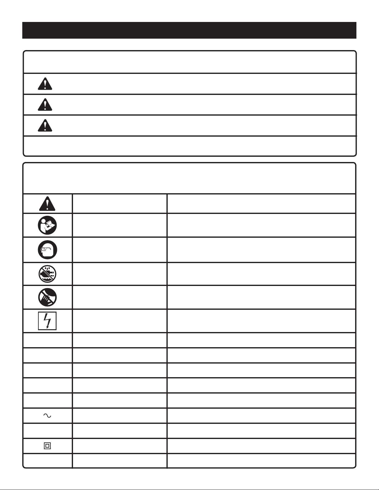
SYMBOLS
The following signal words and meanings are intended to explain the levels of risk associated with this product.
SYMBOL SIGNAL MEANING
DANGER:
WARNING:
CAUTION:
NOTICE:
Some of the following symbols may be used on this product . Please study them and learn their meaning. Proper
interpretation of these symbols will allow you to operate the product better and safer.
SYMBOL NAME
Safety Alert Indicates a potential personal injury hazard.
Read Operator’s Manual
Eye Protection
Indicates an imminently hazardous situation, which, if not avoided, will result
in death or serious injury.
Indicates a potentially hazardous situation, which, if not avoided, could result
in death or serious injury.
Indicates a potentially hazardous situation, which, if not avoided, may result in
minor or moderate injury.
(Without Safety Alert Symbol) Indicates important information not related to an
injury hazard, such as a situation that may result in property damage.
DESIGNATION/EXPLANATION
To reduce the risk of injury, user must read and understand
operator’s manual before using this product.
Always wear eye protection with side shields marked to comply with
ANSI Z87.1.
Wet Conditions Alert Do not expose to rain or use in damp locations.
No Hands Symbol
Electrocution Failure to properly ground can result in electrocution.
V
A Amperes Current
Hz Hertz Frequency (cycles per second)
W Watt Power
min
n
o
Volts Voltage
Minutes Time
Alternating Current Type of current
No Load Speed Rotational speed, at no load
Class II Construction Double-insulated construction
Failure to keep your hands away from the cutting wheel will result
in serious personal injury.
.../min Per Minute Revolutions, strokes, surface speed, orbits etc., per minute
6 — English
Page 7
ELECTRICAL
DOUBLE INSULATION
Double insulation is a concept in safety in electric power
tools, which eliminates the need for the usual threewire grounded power cord. All exposed metal parts are
isolated from the internal metal motor components with
protecting insulation. Double insulated tools do not need
to be grounded.
WARNING:
The double insulated system is intended to protect
the user from shock resulting from a break in the tool’s
internal insulation. Observe all normal safety precautions
to avoid electrical shock.
NOTE: Servicing of a product with double insulation requires
extreme care and knowledge of the system and should
be performed only by a qualified service technician. For
service, we suggest you return the product to your nearest authorized service center for repair. Always use original
factory replacement parts when servicing.
ELECTRICAL CONNECTION
This product has a precision-built electric motor. It should
be connected to a power supply that is 120 volts (AC only
normal household current), 60 Hz. Do not operate this
product on direct current (DC). A substantial voltage drop
will cause a loss of power and the motor will overheat. If
the product does not operate when plugged into an outlet,
double-check the power supply.
EXTENSION CORDS
When using a power tool at a considerable distance from
a power source, be sure to use an extension cord that has
the capacity to handle the current the product will draw. An
undersized cord will cause a drop in line voltage, resulting in
overheating and loss of power. Use the chart to determine
the minimum wire size required in an extension cord. Only
round jacketed cords listed by Underwriter’s Laboratories
(UL) should be used.
When working outdoors with a product , use an extension
cord that is designed for outside use. This type of cord is
designated with “WA” or “W” on the cord’s jacket.
Before using any extension cord, inspect it for loose or
exposed wires and cut or worn insulation.
**Ampere rating (on product data plate)
0-2.0 2.1-3.4 3.5-5.0 5.1-7.0 7.1-12.0 12.1-16.0
Cord Length Wire Size (A.W.G.)
WARNING:
Keep the extension cord clear of the working area.
Position the cord so that it will not get caught on
lumber, tools, or other obstructions while you are working
with a power tool. Failure to do so can result in serious
personal injury.
WARNING:
Check extension cords before each use. If damaged
replace immediately. Never use the product with a
damaged cord since touching the damaged area could
cause electrical shock resulting in serious injury.
GROUND FAULT CIRCUIT INTERRUPTER
See Figure 1, page 15.
This unit is equipped with a Ground Fault Circuit Interrupter
(GFCI), which guards against the hazards of ground fault
currents. An example of ground fault current is the current
that would flow through a person who is using an appliance
with faulty insulation and, at the same time, is in contact
with an electrical ground such as a plumbing fixture, wet
floor, or earth.
GFCI plugs do not protect against short circuits, overloads,
or shocks.
NOTE: The GFCI plug provided will “open” each time that
it is disconnected from the AC wall receptacle. To ensure
readiness for use, press the reset button each time you connect the tool to the power supply.
The GFCI plug can be tested with the TEST and RESET
buttons.
To test:
Depress the TEST button. This should cause the RESET
button to pop out.
To restore power, depress the RESET button.
Perform this test monthly to ensure proper operation of the
GFCI.
WARNING:
Do not operate tool without GFCI intact. Do not replace
cord in order to bypass the GFCI. If the cord is damaged,
do not use the product, take the product to an authorized
service center for repair. Failure to do so can result in serious
personal injury.
25' 16 16 16 16 14 14
50' 16 16 16 14 14 12
100' 16 16 14 12 10 —
**Used on 12 gauge - 20 amp circuit.
NOTE: AWG = American Wire Gauge
7 — English
Page 8

ELECTRICAL
POSITION OF THE TILE SAW
See Figure 2, page 15.
To avoid the possibility of the tool plug or outlet getting
wet, position tile saw to one side of a wall-mounted outlet
to prevent water from dripping onto the outlet or plug. The
operator should arrange a “drip loop” in the cord connecting
the saw to the outlet. The “drip loop” is that part of the cord
below the level of the outlet, or the connector if an extension
cord is used, to prevent water traveling along the cord and
coming in contact with the outlet.
FEATURES
PRODUCT SPECIFICATIONS
Wheel Diameter (Included) ........................................... 4 in.
Wheel Diameter (Max Capacity) .............................4-3/8 in.
Cutting wheel Arbor .................................................. 5/8 in.
Cutting Depth at 0º ...............................................1-5/32 in.
If the plug or outlet does get wet, DO NOT unplug the cord.
Disconnect the fuse or circuit breaker that supplies power
to the tool then unplug and examine for the presence of
water in the outlet.
WARNING:
To reduce the risk of electrocution, keep all connections
dry and off the ground. Do not touch the plug with wet
hands.
Cutting Depth at 45º .................................................. 3/4 in.
No Load Speed ...................................13,700 r/min. (RPM)
Wheel Type ......................Continuous Rim Diamond Wheel
Input ................................. 120 V, AC only, 60 Hz, 12 Amps
KNOW YOUR TILE SAW
See Figure 3, page 15.
The safe use of this product requires an understanding of
the information on the product and in this operator’s manual
as well as a knowledge of the project you are attempting.
Before use of this product, familiarize yourself with all
operating features and safety rules.
BEVEL ADJUSTMENT
The bevel adjustment feature allows you to make bevel cuts
up to 45º.
CONTINUOUS RIM DIAMOND WHEEL
The continuous rim diamond wheel provided with this saw
is for wet cutting only. Dry cutting is possible with the use
of an optional cutting wheel marked as usable for dry cutting (not included). This tile saw will accept either a 4” or a
4-3/8” (111 mm) continuous rim cutting wheel.
DEPTH ADJUSTMENT
Change the depth of cut from 0 to 1-5/32 in. using the depth
adjustment knob.
ERGONOMIC DESIGN
The design provides comfort when operating in different
positions and at different angles.
GFCI PLUG
The saw is equipped with a GFCI plug to guard against the
hazards of ground fault currents. This plug does not protect
against short circuits, overloads, or shocks.
LOCK-ON BUTTON
The lock-on button is convenient for continuous use for
extended periods of time.
WATER SUPPLY KIT
For wet tile cutting, install the water supply kit and connect
to an appropriate water supply.
8 — English
Page 9
ASSEMBLY
UNPACKING
This product requires assembly.
Carefully remove the product and any accessories from
the box. Make sure that all items listed in the packing list
are included.
WARNING:
Items in this Assembly section are not assembled to the
product by the manufacturer and require customer installation. Use of a product that may have been improperly
assembled could result in serious personal injury.
If any parts are damaged or missing, please call
1-800-525-2579 for assistance. In Mexico, please call
01-800-843-1111.
WARNING:
If any parts are damaged or missing do not operate
this product until the parts are replaced. Use of this
product with damaged or missing parts could result in
serious personal injury.
WARNING:
Do not attempt to modify this product or create accessories not recommended for use with this product. Any
such alteration or modification is misuse and could result
in a hazardous condition leading to possible serious
personal injury.
ATTACHING WATER SUPPLY KIT
See Figure 4, page 15.
The water supply must come from a fresh water main. NEVER
turn the water supply on high. The water supply valve provides
a convenient on/off control lever for starting and stopping
the water flow onto the cutting wheel.
Unplug the saw.
Attach the water supply kit to the saw as shown using
the screw provided. Tighten securely.
With the faucet turned completely off, attach the faucet
adaptor to a garden hose or outdoor faucet.
Once the cutting wheel is installed, the tile saw is ready
to be used.
NOTE: The tool is rated for a maximum water pressure of
60psi.
NOTE: For dry cutting, it is not necessary to install the water
supply kit.
WARNING:
A 4-3/8 in. (111 mm) wheel is the maximum wheel capacity of the saw. Also, never use a wheel that is too thick to
allow outer cutting wheel washer to engage with the flat
on the spindle. Larger wheels will come in contact with
the wheel guards, while thicker wheels will prevent cutting
wheel screw from securing wheel on spindle. Either of
these situations could result in a serious accident.
WARNING:
WARNING:
Do not connect to power supply until assembly is
complete. Failure to comply could result in accidental
starting and possible serious personal injury.
9 — English
Do not use cutting wheels rated less than the no load
speed of this tool. Failure to heed this warning could
result in personal injury. Do not use wheel with cracks,
gaps, or teeth.
WARNING:
Do not use toothed or segmented wheels. Use only
continuous rimmed diamond wheels suited for masonry
materials.
Page 10
ASSEMBLY
INSTALLING CUTTING WHEEL
See Figures 5 - 6, page 16.
Unplug the saw.
Hold the outer cutting wheel washer still using the hex
box wrench.
With your other hand, use the hex “T” wrench to remove
the cutting wheel screw by turning it clockwise.
Remove outer cutting wheel washer.
WARNING:
If inner flange bushing has been removed, replace it
before placing wheel on spindle. Failure to do so will
prevent wheel from tightening properly and could result
in serious personal injury.
OPERATION
DANGER:
Keep hands away from cutting area and the cutting
wheel. Keep your second hand on auxiliary handle, or
motor housing. If both hands are holding the saw, they
cannot be cut by the cutting wheel.
WARNING:
Check to see that the arrow on the wheel and the arrow
on the saw are pointing in the same direction.
Fit the cutting wheel inside the wheel guard between the
two nozzles of the water supply and onto the inner flange
bushing.
Replace the outer cutting wheel washer.
Hold the outer cutting wheel washer still using the hex
box wrench.
Align the outer cutting wheel washer with the inner cutting
wheel bushing until it engages.
Tighten cutting wheel screw securely by turning it coun-
terclockwise with the hex “T” wrench.
NOTE: Never use a wheel that is too thick to allow the
outer cutting wheel washer to engage with the flat on the
spindle.
NOTICE:
Before each use, inspect the entire product for damaged,
missing, or loose parts such as screws, cutting wheel
washers, hoses, fittings, etc. Tighten securely all screws,
washers and fittings and do not operate this product until
all missing or damaged parts are replaced. Please call
1-800-525-2579 or contact an authorized service center
for assistance.
Do not allow familiarity with this product to make you
careless. Remember that a careless fraction of a second is
sufficient to inflict serious injury.
WARNING:
Always wear eye protection with side shield marked to
comply with ANSI Z87.1. Failure to do so could result in
objects being thrown into your eyes resulting in possible
serious injury.
WARNING:
Do not use any attachments or accessories not
recommended by the manufacturer of this product. The
use of attachments or accessories not recommended
can result in serious personal injury.
10 — English
APPLICATIONS
You may use this product for the purpose listed below:
Wet or dry cross cutting, rip cutting, and bevel cutting of
man-made tile, pavers, and natural stone tile products
CUTTING WHEELS
The best of cutting wheels will not cut efficiently if they are
dull or badly worn. Using a dull wheel will place a heavy
load on the saw. Keep extra wheels on hand, so that sharp
wheels are always available.
WARNING:
Since wheel is exposed on underside of work, keep
hands and fingers away from cutting area. Any part of
your body coming in contact with moving wheel may
result in serious injury.
STARTING/STOPPING THE SAW
See Figure 7, page 16.
To start the saw: Depress the switch trigger.
Always let the wheel reach full speed, then guide the saw
into the workpiece.
Page 11
OPERATION
To stop the saw: Release the switch trigger.
After you release the switch trigger, allow the wheel to come
to a complete stop. DO NOT remove the saw from the
workpiece while the wheel is moving.
LOCK-ON BUTTON
See Figure 7, page 16.
The saw is equipped with a lock-on feature, which is convenient for continuous use for extended periods of time.
To lock-on:
Depress the switch trigger.
Push in and hold the lock-on button, located on the side
of the handle.
Release the switch trigger.
Release the lock-on button.
To release the lock, depress and release the switch
trigger.
ADJUSTING CUTTING WHEEL DEPTH
See Figure 8, page 16.
Always keep correct wheel depth setting. The correct wheel
depth setting for all cuts should not exceed 1/4 in. below the
material being cut. More wheel depth will increase the chance
of kickback and cause the cut to be rough.
To adjust the wheel depth:
Unplug the saw.
To make the best possible cut:
Hold the saw firmly.
Avoid placing your hand on the workpiece while making
a cut.
Support the workpiece so that the cut is always on your left.
Support the workpiece near the cut.
Clamp the workpiece securely so that the workpiece will
not move during the cut.
Avoid placing the saw on the part of the workpiece that
will fall off when the cut is made.
Place the workpiece with the “good” side down.
Draw a guideline along the desired line of cut before
beginning your cut.
Keep the cord away from the cutting area. Always place
the cord to prevent it from hanging up on the workpiece
while making a cut.
If wet cutting is desired, turn the water supply valve to
start water flow.
DANGER:
If the cord hangs up on the workpiece during a cut,
release the switch trigger immediately and allow the
wheel to come to a complete stop. Unplug the saw and
reposition the cord to prevent it from hanging up again.
WARNING:
Failure to unplug the tool could result in accidental starting causing serious injury.
Loosen depth lock knob by turning it counter-clockwise.
Hold base flat against the workpiece and raise or lower
saw until the desired depth of cut is reached.
Tighten depth lock knob securely by turning it clockwise.
OPERATING THE SAW
See Figures 9 - 10, page 16.
It is important to understand the correct method for operating the saw. Refer to the figures in this section to learn the
correct and incorrect ways for handling the saw.
WARNING:
To make sawing easier and safer, always maintain proper
control of the saw. Loss of control could cause an accident resulting in possible serious injury.
WARNING:
When lifting the saw from the workpiece, the wheel is
exposed on the underside of the saw.
DANGER:
Using a saw with a damaged cord could result in serious
injury or death. If the cord has been damaged, have it
replaced before using the saw again.
MAKING CUTS
Always draw the line to be cut on the tile using a marker or
grease pencil. If the tile is shiny and hard-to-mark, place
masking tape on the tile and mark the tape.
A common problem when cutting tile is straying from the
marked line. Once you’ve strayed from the mark, you can not
force the wheel back to the line by twisting the tile. Instead,
back up and recut the tile slicing off a small amount of tile
until the wheel is back on track.
To avoid this problem, use a straight edge guide whenever
possible for making cross cuts and miter cuts.
If wet cutting is desired, it should be performed outside.
TO MAKE A CROSS CUT
See Figure 11, page 16.
Cross cuts are straight 90º cuts. The material is fed into the
cut at a 90º angle to the wheel, and the wheel is vertical.
Using a marker or grease pencil, mark the area to be cut
on material.
Secure the workpiece.
11 — English
Page 12

OPERATION
If wet cutting is desired, turn the water supply valve to
start water flow.
Depress the switch trigger to start the saw.
Let the cutting wheel build up to full speed and wait for
the wheel to get wet before moving the wheel into the
material.
When the cut is made, release the switch trigger. Wait
for the cutting wheel to come to a complete stop before
removing the saw from the material.
Stop the water flow.
TO MAKE A DIAGONAL CUT
See Figure 12, page 16.
Diagonal cuts are also referred to as “long point to long
point cuts”.
Using a marker or grease pencil, mark the area to be cut
on material.
Secure the workpiece.
If wet cutting is desired, turn the water supply valve to
start water flow.
Depress the switch trigger to start the saw.
Let the cutting wheel build up to full speed and wait for
the wheel to get wet before moving the wheel into the
material.
When the cut is made, release the switch trigger. Wait
for the cutting wheel to come to a complete stop before
removing the saw from the material.
Stop the water flow.
TO MAKE A MITER CUT
See Figure 13, page 17.
Miter cuts are used for cutting outside and inside corners
with the material at any angle to the wheel other than 90°.
Miter cuts tend to “creep” during cutting. This can be controlled by holding the workpiece securely against a straight
edge guide.
Using a marker or grease pencil, mark the area to be cut
on material.
Secure the workpiece.
If wet cutting is desired, turn the water supply valve to
start water flow.
Depress the switch trigger to start the saw.
Let the cutting wheel build up to full speed and wait for
the wheel to get wet before moving the wheel into the
material.
When the cut is made, release the switch trigger. Wait
for the cutting wheel to come to a complete stop before
removing the saw from the material.
Stop the water flow.
TO MAKE AN L-CUT
See Figure 14, page 17.
L-cuts are cuts that remove a piece of tile to fit in a corner,
around a cabinet, or a piece of molding and are made by
two separate cuts.
NOTE: Only overcut on the bottom or underneath side of
the material being cut.
Using a marker or grease pencil, mark the area to be cut
on both sides of the material.
Secure the workpiece.
If wet cutting is desired, turn the water supply valve to
start water flow.
Depress the switch trigger to start the saw.
Let the cutting wheel build up to full speed and wait for the
wheel to get wet before moving the wheel into the material.
Make the cut far enough into the material without overcut-
ting.
Release the switch trigger. Wait for the cutting wheel to
come to a complete stop before removing the saw from
the material.
Turn the material over and make the cut along one of the
marks. This time overcut the other line and the cut piece
should separate from the rest of the material.
Depress the switch trigger.
Let the cutting wheel build up to full speed and wait for the
wheel to get wet before moving the wheel into the material.
When the cut is made, release the switch trigger. Wait
for the cutting wheel to come to a complete stop before
removing the saw from the material.
Stop the water flow.
TO MAKE A BEVEL CUT
See Figure 15, page 17.
Beveled 45° cuts can be made by adjusting the position of
the motor head.
Using a marker or grease pencil, mark the area to be cut
on material.
Secure the workpiece.
Loosen the bevel lock knob on the front of the saw.
Rotate the base until you reach the desired angle setting
on the bevel scale.
Tighten the bevel lock knob securely.
If wet cutting is desired, turn the water supply valve to
start water flow.
Depress the switch trigger to start the saw.
Let the cutting wheel build up to full speed and wait for the
wheel to get wet before moving the wheel into the material.
When the cut is made, release the switch trigger. Wait
for the cutting wheel to come to a complete stop before
removing the saw from the material.
Stop the water flow.
12 — English
Page 13
MAINTENANCE
WARNING:
When servicing, use only identical replacement parts.
Use of any other parts can create a hazard or cause
product damage.
WARNING:
Always wear eye protection with side shields marked
to comply with ANSI Z87.1 during product operation. If
operation is dusty, also wear a dust mask.
GENERAL MAINTENANCE
Avoid using solvents when cleaning plastic parts. Most
plastics are susceptible to damage from various types of
commercial solvents and may be damaged by their use. Use
clean cloths to remove dirt, dust, oil, grease, etc.
WARNING:
Do not at any time let brake fluids, gasoline, petroleumbased products, penetrating oils, etc., come in contact
with plastic parts. Chemicals can damage, weaken or
destroy plastic which can result in serious personal injury.
Electric tools used on fiberglass material, wallboard, spackling compounds, or plaster are subject to accelerated wear
and possible premature failure because the fiberglass chips
and grindings are highly abrasive to bearings, brushes,
commutators, etc. Consequently, we do not recommend
using this product for extended work on these types
of materials. However, if you do work with any of these
materials, it is extremely important to clean the product
using compressed air.
LUBRICATION
All of the bearings in this product are lubricated with a
sufficient amount of high grade lubricant for the life of the
unit under normal operating conditions. Therefore, no further
lubrication is required.
POWER SUPPLY CORD REPLACEMENT
If replacement of the power supply cord is necessary, this
must be done by an authorized service center in order to
avoid a safety hazard.
BRUSH REPLACEMENT
See Figure 16, page 15.
NOTE: This saw is equipped with two externally accessible
brushes located on either side of the saw housing.
Unplug the saw.
WARNING:
Failure to unplug the tool could result in accidental starting causing possible serious injury.
Remove brush caps using a screwdriver.
Remove brush assemblies.
Check for wear. Replace both brush assemblies when
either has less than 1/4 in. length of carbon remaining.
NOTE: Do not replace one side without replacing the
other.
Reassemble using new brush assemblies. Make sure
curvature of brush matches curvature of motor and that
brush moves freely in brush tube.
Reassemble by reversing the steps listed above.
Tighten brush caps securely. Do not over tighten.
WHEEL MAINTENANCE
If wheel cutting ability deteriorates or becomes slow, the wheel
may need resurfacing. Cutting a brick paver will resurface
the wheel and improve wheel cutting ability.
NOTE: ILLUSTRATIONS START ON PAGE 15
AFTER FRENCH AND SPANISH LANGUAGE SECTIONS
13 — English
Page 14

NOTES
14 — English
Page 15

AVERTISSEMENTS GÉNÉRAUX DE SÉCURITÉ EN CE QUI A
TRAIT AUX OUTILS ÉLECTRIQUES
SÉCURITÉ PERSONNELLE
AVERTISSEMENT !
Lire toutes les règles et toutes les instructions de sécurité.Ne
pas suivre l’ensemble des avertissements et des instructions peut
entraîner une électrocution, un incendie ou des blessures graves.
Conserver les avertissements et les instructions à des fins
de référence ultérieure. Le terme « outil électrique » utilisé
dans les avertissements fait référence aux outils électriques
(avec fil) à alimentation sur secteur ou aux outils électriques
(sans fil) alimentés par batterie.
LIEU DE TRAVAIL
Garder le lieu de travail propre et bien éclairé. Les endroits
encombrés ou sombres sont propices aux accidents.
Ne pas utiliser d’outils électriques dans des atmosphères
explosives, par exemple en présence de liquides, gaz ou
poussières inflammables. Les outils électriques produisent
des étincelles risquant d’enflammer les poussières ou
vapeurs.
Garder les enfants et badauds à l’écart pendant
l’utilisation d’un outil électrique. Les distractions peuvent
causer une perte de contrôle.
SÉCURITÉ ÉLECTRIQUE
Les fiches des outils électriques doivent correspondre
à la prise secteur utilisée. Ne jamais modifier la fiche,
de quelque façon que ce soit. Ne jamais utiliser
d’adaptateurs de fiche avec des outils mis à la terre. Les
fiches et prises non modifiées réduisent le risque de choc
électrique.
Éviter tout contact du corps avec des surfaces mises
à la terre, telles que tuyaux, radiateurs, cuisinières et
réfrigérateurs. Le risque d’électrocution est accru lorsque
le corps est mis à la terre.
Ne pas exposer les outils électriques à l’eau ou l’humidité.
La pénétration d’eau dans ces outils accroît le risque de choc
électrique.
Ne pas maltraiter le cordon d’alimentation. Ne jamais
utiliser le cordon d’alimentation pour transporter l’outil et
ne jamais débrancher ce dernier en tirant sur le cordon.
Garder le cordon à l’écart de la chaleur, de l’huile, des
objets tranchants et des pièces en mouvement. Un
cordon endommagé ou emmêlé accroît le risque de choc
électrique.
Pour les travaux à l’extérieur, utiliser un cordon
spécialement conçu à cet effet. Utiliser un cordon conçu
pour l’usage extrérieur réduit les risques de choc électrique.
S’il est nécessaire d’utiliser l’outil électrique dans un
endroit humide, employer un dispositif interrupteur de
défaut à la terre (GFCI). L’utilisation d’un GFCI réduit le
risque de décharge électrique.
Rester attentif, prêter attention au travail et faire preuve
de bon sens lors de l’utilisation de tout outil électrique.
Ne pas utiliser cet outil en état de fatigue ou sous
l’influence de l’alcool, de drogues ou de médicaments.
Un moment d’inattention pendant l’utilisation d’un outil
électrique peut entraîner des blessures graves.
Utiliser l’équipement protectif blessures. Toujours porter
une protection oculaire. L’équipement protectif tel qu’un
masque filtrant, de chaussures de sécurité, d’un casque
ou d’une protection auditive, utilisé dans des conditions
appropriées réduira le risque de blessures.
Empêcher les démarrages accidentels. S’assurer que la
gâchette est en position d’arrêt avant de brancher l’outil
à une source de courant ou d’insérer la batterie, de le
ramasser ou de le transporter. Le fait de transporter l’outil
en gardant le doigt sur la gâchette ou de le brancher lorsque
la gâchette est en position de marche favorise les accidents.
Retirer les clés de réglage avant de mettre l’outil en
marche. Une clé laissée sur une pièce rotative de l’outil
peut causer des blessures.
Ne pas travailler hors de portée. Toujours se tenir bien
campé et en équilibre. Ceci permettra de mieux contrôler
l’outil en cas de situation imprévue.
Porter une tenue appropriée. Ne porter ni vêtements
amples, ni bijoux. Garder les cheveux, les vêtements
et les gants à l’écart des pièces en mouvement. Les
vêtements amples, bijoux et cheveux longs peuvent se
prendre dans les pièces en mouvement.
Si les outils sont équipés de dispositifs de dépoussiérage,
s’assurer qu’ils sont connectés et correctement utilisés.
L’utilisation d’un dépoussiéreur peut réduire les risques liés
à la poussière.
Ne porter ni vêtements amples, ni bijoux. Attacher ou
couvrir les cheveux longs. Les vêtements amples, bijoux et
cheveux longs peuvent se prendre dans les ouïes d’aération.
Ne pas utiliser l’outil sur une échelle ou un support
instable. Une bonne tenue et un bon équilibre permettent
de mieux contrôler l’outil en cas de situation imprévue.
UTILISATION ET ENTRETIEN DE L’OUTILS
MOTORISÉS
Ne pas forcer l’outil. Utiliser un outil approprié pour
le travail. Un outil approprié exécutera le travail mieux et
de façon moins dangereuse s’il est utilisé dans les limites
prévues.
Ne pas utiliser l’outil si le commutateur ne permet pas
de le mettre en marche et de l’arrêter. Tout outil qui ne
peut pas être contrôlé par son commutateur est dangereux
et doit être réparé.
Débrancher l’outil et / ou retirer le bloc de batteries avant
d’effectuer des réglages, de changer d’accessoire ou de
ranger l’outil. Ces mesures de sécurité réduisent les risques
de démarrage accidentel de l’outil.
2 — Français
Page 16

AVERTISSEMENTS GÉNÉRAUX DE SÉCURITÉ EN CE QUI A
TRAIT AUX OUTILS ÉLECTRIQUES
Ranger lesoutils électriqueshors deportée des enfantset
ne laisser personne n’étant pas familiarisé avec le
fonctionnement de l’outil ou ces instructions utiliser
l’outil. Dans les mains de personnes n’ayant pas reçu des
instructions adéquates, les outils sont dangereux.
Veiller à entretenir les outils électriques. Vérifier
qu’aucune pièce mobile n’est mal alignée, grippée ou
brisée et s’assurer qu’aucun autre problème risque
d’affecter le bon fonctionnement de l’outil. En cas de
dommages, faire réparer l’outil avant de l’utiliser de
nouveau. Beaucoup d’accidents sont causés par des outils
mal entretenus.
Garder les outils bien affûtés et propres. Des outils
correctement entretenus et dont les tranchants sont bien
affûtés risquent moins de se bloquer et sont plus faciles à
contrôler.
MESURES DE SÉCURITÉ POUR LES
OPÉRATIONS DE TRONÇONNAGE PAR MEULE
Le protège-meule doit être fixé solidement à l’outil
électrique et positionné de manière à garantir une
sécurité optimale et qu’une plus petite partie de la meule
soit dirigée vers l’utilisateur. Éloigner le corps et les
spectateurs du plan de rotation de la meule. Le protège-
meule aide à protéger l’utilisateur contre la projection de
fragments de meule brisés et le contact accidentel avec la
meule.
Utiliser seulement des meules diamants avec cet outil
électrique. Le simple fait qu’un accessoire puisse être
installé sur l’outil électrique ne signifie pas qu’il peut être
utilisé en toute sécurité.
La vitesse de rotation nominale de l’accessoire doit au
moins être égale à la vitesse maximale indiquée sur l’outil
électrique. Les accessoires utilisés à une vitesse supérieure
à leur vitesse de rotation nominale peuvent se briser et se
détacher.
Utiliser seulement les meules pour effectuer les
opérations pour lesquelles elles sont conçues. Par
exemple : Ne pas utiliser le côté d’une meule pour
tronçonner. Les meules à tronçonner sont conçues pour la
rectification périphérique et l’application d’une force latérale
sur les meules peut provoquer leur bris.
Toujours utiliser des meules à collerettes intactes et de
diamètre conforme à la meule choisie. Les collerettes de
meule conformes soutiennent la meule tout en minimisant
les risques de bris de la meule.
3 — Français
Utiliser l’outil électrique, les accessoires, les grains etc.
conformément à ces instructions en tenant compte des
conditions de travail et de la tâche à effectuer. L’utilisation
de cet outil électrique pour effectuer une opération pour
laquelle il n’est pas conçu peut occasionner une situation
dangereuse.
DÉPANNAGE
Les réparations doivent être confiées à un technicien
qualifié, utilisant exclusivement des pièces identiques
à celles d’origine. Ceci assurera le maintien de la sécurité
de l’outil.
Utiliser exclusivement des pièces identiques à celles
d’origine pour les réparations. Se conformer aux
instructions de la section Entretien de ce manuel.
L’usage de pièces non autorisées ou le non-respect des
instructions peut présenter des risques de choc électrique
ou de blessures.
Le diamètre extérieur et l’épaisseur de l’accessoire
doivent être conformes à la puissance nominale de l’outil
électrique. Il est impossible de protéger ou de contrôler
adéquatement un accessoire de dimension inappropriée.
Le diamètre de l’arbre des meules et des collerettes
doivent être parfaitement adaptés à la broche de l’outil
électrique. Les meules et collerettes équipées d’alésages
centraux ne correspondant pas à la quincaillerie de montage
de l’outil se déstabiliseront, vibreront de façon excessive et
pourront causer une perte de contrôle.
Ne pas utiliser des meules endommagées. Avant chaque
utilisation, vérifier et s’assurer que les meules ne sont
pas brisées et ne comportent pas de fissures. Si l’outil
électrique ou l’accessoire est échappé, s’assurer
qu’il n’est pas endommagé ou installer une meule
intacte. Après avoir effectué cette opération, éloigner
le corps et les spectateurs de l’accessoire en rotation
et faire fonctionner l’outil à sa vitesse à vide maximale
pendant une minute. Les meules endommagées se brisent
généralement lors de cet essai.
Porter un équipement de protection personnel. Selon le
travail à effectuer, porter un écran facial, des lunettes
de sécurité ou des lunettes étanches. Au besoin, porter
également un masque antipoussière, un protecteur
d’oreilles, des gants et un tablier d’atelier résistant aux
petits fragments abrasifs ou aux fragments provenant
des pièces à travailler. Le protecteur oculaire utilisé
doit résister aux débris projetés par diverses opérations.
Le masque antipoussière ou le respirateur doit pouvoir
empêcher l’infiltration de particules produites par le travail.
Une exposition prolongée à un bruit fort peut provoquer une
perte auditive.
Page 17

SAFETY INSTRUCTIONS FOR
ABRASIVE CUTTING-OFF OPERATIONS
S’assurer qu’aucun spectateur ne se tient à proximité
du lieu de travail. Toute personne entrant sur le lieu de
travail doit porter l’équipement de protection personnel.
Des fragments provenant d’une pièce à travailler ou d’un
accessoire brisé peuvent être projetés et causer des
blessures, même à des personnes se tenant à une certaine
distance du lieu de travail immédiat.
Lorsque l’outil est utilisé pour un travail risquant de le
mettre en contact avec des fils électriques cachés ou
avec son propre cordon d’alimentation, le tenir par les
surfaces de prise isolées. Tout contact avec un fil sous
tension électrifierait les parties métalliques de l’outil, et
causerait un choc électrique.
Tenir le cordon loin de l’accessoire en rotation. En cas de
perte de contrôle, le cordon peut se couper ou être tiré, et la
main ou le bras de l’utilisateur risquent d’entrer en contact
avec l’accessoire en rotation.
Ne jamais déposer l’outil électrique avant l’arrêt complet
de l’accessoire. La meule en rotation peut gripper la surface
et occasionner une perte de contrôle de l’outil électrique.
Ne jamais faire fonctionner l’outil électrique en le
transportant à ses côtés. L’accessoire en rotation peut
s’accrocher accidentellement aux vêtements et entrer en
contact avec l’utilisateur.
Nettoyer régulièrement les grilles d’aération de l’outil
électrique. Le ventilateur du moteur aspire la poussière
dans le bâti et crée une accumulation excessive de métal
fritté, ce qui peut causer un danger électrique.
Ne pas faire fonctionner l’outil électrique à proximité de
matériaux inflammables. Les étincelles peuvent enflammer
ces matériaux.
REBOND ET AVERTISSEMENTS
COMPLÉMENTAIRES :
Le rebond est une réaction soudaine occasionnée par une
meule en rotation se pinçant ou se grippant. Le pincement
ou le grippage provoque le blocage immédiat de la meule
en rotation qui, à son tour, entraîne l’outil incontrôlé dans
le sens opposé à la rotation de l’accessoire, à l’endroit du
pincement.
Par exemple, lorsque la meule se grippe ou se coince dans
la pièce à travailler, le bord de la meule pénétrant dans le
point de pincement peut creuser la surface du matériau et
provoquer son élévation ou sa déviation. La meule peut bondir
vers l’avant ou s’éloigner de l’utilisateur selon la direction du
mouvement de la meule au moment où elle a atteint le point
de pincement. Dans ces conditions d’utilisation, les meules
peuvent également se briser.
Un rebond est causé par à une mauvaise utilisation de
l’outil ou au non-respect des procédures ou des conditions
d’utilisation et peut être évité en respectant les précautions
prescrites ci-dessous :
Tenir fermement l’outil électrique, placer le corps et le
bras de manière à pouvoir résister aux rebonds. Toujours
utiliser la poignée auxiliaire, s’il y en a une, pour assurer
un contrôle optimal en cas de rebond ou de couple de
réaction lors du démarrage de l’outil. L’utilisateur peut
contrôler les rebonds et les couples de réactions s’il respecte
les précautions prescrites.
Ne jamais placer les mains à proximité de l’accessoire
en rotation. En cas de rebond, l’accessoire peut dévier sur
celles-ci.
Ne pas aligner le corps avec la meule en rotation. Un
rebond propulsera l’outil dans le sens opposé au mouvement
de la meule au moment où elle a atteint le point de grippage.
Faire preuve d’une extrême prudence au moment
d’utiliser l’outil sur des coins ou des rebords tranchants
et éviter les rebondissements et le grippage de
l’accessoire. Les coins, les arêtes vives et les surfaces
rebondissantes ont tendance à se gripper à l’accessoire en
rotation et à causer une perte de contrôle ou un rebond.
Ne pas installer une chaîne coupante, une lame à
sculpter le bois, une meule diamant segmentée, ou
une pale dentée De telles lames provoquent de nombreux
rebonds et la perte de contrôle.
S’assurer que la meule à tronçonner ne se coince pas
et éviter d’appliquer une pression excessive. Éviter de
tronçonner sur une profondeur excessive. Une surcharge
sur la meule augmente le collage, la tendance à la torsion ou
au coincement de la meule pendant la coupe et les risques
de rebond ou de bris de la meule.
Si la meule se coince ou si l’opération de coupe est
interrompue pour une raison quelconque, éteindre l’outil
électrique et le maintenir immobile jusqu’à ce que la
meule s’arrête complètement. Ne jamais tenter de retirer
la meule de la pièce tronçonnée tant que la meule tourne
pour éviter le rebond. Déterminer et résoudre la cause du
coincement de la lame..
Ne pas reprendre le tronçonnage directement sur la
pièce à travailler. Permettre à la meule d’atteindre sa
vitesse maximale puis la réinsérer soigneusement dans
le trait de coupe. La meule risque de se coincer, de se
soulever ou de rebondir si cette précaution n’est pas prise.
Soutenir les panneaux et toute pièce à travailler
surdimensionnée afin de minimiser les risques de
pincement et de rebond de la meule. Les pièces à travailler
de grandes dimensions ont tendance à fléchir sous leur
propre poids. Il importe donc de disposer des supports sous
la pièce à travailler, près du trait de coupe et au bord de la
pièce à travailler, des deux côtés de la meule.
Redoubler de prudence lors de la découpe d’évidements
dans des cloisons ou autres endroits sans visibilité
arrière. La partie en saillie de la meule peut couper les
conduites d’eau ou de gaz, le câblage électrique et tout
autre objet pouvant provoquer un rebond.
4 — Français
Page 18

SAFETY INSTRUCTIONS FOR
ABRASIVE CUTTING-OFF OPERATIONS
RÈGLES DE SÉCURITÉ SUPPLÉMENTAIRES
Apprendre à connaître l’outil. Lire attentivement le
manuel d’utilisation. Apprendre les applications et
les limites de l’outil, ainsi que les risques spécifiques
relatifs à son utilisation. Le respect de cette consigne
réduira les risques d’incendie, de choc électrique et de
blessures graves.
Toujours porter une protection oculaire avec écrans
latéraux certifiée conforme à la norme ANSI Z87.1. Si
cette précaution n’est pas prise, des objets peuvent être
projetés dans les yeux et causer des lésions graves.
Protection respiratoire. Porter un masque facial ou
un masque anti-poussière si le travail produit de la
poussière. Le respect de cette consigne réduira les
risques de blessures graves.
Protection auditive. Porter une protection auditive
lors de l’utilisation prolongée. Le respect de cette règle
réduira les risques de blessures graves.
Inspecter régulièrement les cordons d’alimentation
des outils et s’ils sont endommagés, les confier au
centre de réparations agréé le plus proche. Toujours
être conscient de l’emplacement du cordon. Le respect
de cette règle réduira les risques de choc électrique et
d’incendie.
Garder le raccordement de la rallonge au sec et loin
du sol pour réduire le risque d’électrocution. Garder
l’outil au sec lorsque vous appliquez de l’eau sur la meule.
Ne pas vous tenir debout dans l’eau lorsque vous opérez
l’outil. Ne pas toucher à la prise avec les mains mouillées.
Garder les personnes à l’écart de l’eau et de l’électricité.
Vérifier l’état des pièces. Avant d’utiliser l’outil de
nouveau examiner soigneusement les pièces et
dispositifs de protection qui semblent endommagés
afin de déterminer s’ils fonctionnent correctement
et s’ils remplissent les fonctions prévues. Vérifier
l’alignement des pièces mobiles, s’assurer qu’aucune
pièce n’est bloquée ou cassée, vérifier la fixation de
chaque pièce et s’assurer qu’aucun autre problème
ne risque d’affecter le bon fonctionnement de l’outil.
Toute protection ou pièce endommagée doit être
correctement réparée ou remplacée dans un centre
de réparations agréé. Le respect de cette consigne
réduira les risques de choc électrique, d’incendie et de
blessures graves.
S’assurer que le cordon prolongateur est en bon état.
Si un cordon prolongateur est utilisé, s’assurer que
sa capacité est suffisante pour supporter le courant
de fonctionnement de l’outil. Un calibre de fil (A.W.G)
d’au minimum 14 est recommandé pour un cordon
prolongateur de 7,6 m (25 pi) ou moins. L’usage d’un
cordon de plus de 30 m (100 pi) est déconseillé. En cas
de doute, utiliser un cordon du calibre immédiatement
supérieur. Moins le numéro de calibre est élevé, plus
la capacité du fil est grande. Un cordon de capacité
insuffisante causerait une baisse de la tension de ligne,
entraînant une perte de puissance et une surchauffe.
Si le cordon d’alimentation est endommagé, il doit être
remplacé uniquement pas le fabricant ou par un centre
de réparation agréé pour éviter tout risque.
Conserver ces instructions. Les consulter fréquemment
et les utiliser pour instruire les autres utilisateurs
éventuels. Si cet outil est prêté, il doit être accompagné
de ces instructions.
PROPOSITION 65 DE LA CALIFORNIE
AVERTISSEMENT :
Ce produit et la poussière dégagée lors du ponçage, sciage, meulage, perçage de certains matériaux et lors d’autres opérations
de construction contient des produits chimiques reconnus causer le cancer, des malformations congénitales ou des lésions
de l’appareil reproducteur. Bien se laver les mains après toute manipulation.
Voici certains exemples de ces produits chimiques :
• le plomb contenu dans la peinture au plomb,
• la silice cristalline contenue dans les briques, le béton et d’autres produits de maçonnerie, ainsi que
• l’arsenic et le chrome contenus dans le bois de construction traité par produits chimiques.
Le risque présenté par l’exposition à ces produits varie en fonction de la fréquence de ce type de travail. Pour réduire
l’exposition,: travailler dans un endroit bien aéré et utiliser des équipements de sécurité approuvés tels que masques
antipoussière spécialement conçus pour filtrer les particules microscopiques.
5 — Français
Page 19

SYMBOLES
Les termes de mise en garde suivants et leur signification ont pour but d’expliquer le degré de risques associé à
l’utilisation de ce produit.
SYMBOLE SIGNAL SIGNIFICATION
DANGER :
AVERTISSEMENT :
ATTENTION :
AVIS :
Certains des symboles ci-dessous peuvent être présents sur le produit. Veiller à les étudier et à apprendre leur signification.
Une interprétation correcte de ces symboles permettra d’utiliser l’outil plus efficacement et de réduire les risques.
SYMBOLE
Symbole d’alerte de sécurité Indique un risque de blessure potentiel.
Lire le manuel d’utilisation
Protection oculaire
NOM
Indique une situation extrêmement dangereuse qui, si elle n’est pas
évitée, aura pour conséquences des blessures graves ou mortelles.
Indique une situation potentiellement dangereuse qui, si elle n’est pas
évitée, pourrait entraîner des blessures graves ou mortelles.
Indique une situation potentiellement dangereuse qui, si elle n’est pas
évitée, pourraît entraîner des blessures légères ou de gravité modérée.
(Sans symbole d’alerte de sécurité) Indique une information importante
ne concernant pas un risque de blessure comme une situation pouvant
occasionner des dommages matériels.
DÉSIGNATION / EXPLICATION
Pour réduire les risques de blessures, l’utilisateur doit lire et veiller à
bien comprendre le manuel d’utilisation avant d’utiliser ce produit.
Toujours porter une protection oculaire avec écrans latéraux certifiée
conforme à la norme ANSI Z87.1.
Avertissement concernant
l’humidité
Symbole garder les mains à
l’écart
Électrocution Une mauvaise mise à la terre peut causer une électrocution.
V
A Ampères Intensité
Hz Hertz Fréquence (cycles par seconde)
W Watts Puissance
min Minutes Temps
n
o
Volts Tension
Courant alternatif Type de courant
Vitesse à vide Vitesse de rotation à vide
Construction de classe II Construction à double isolation
Ne pas exposer l’outil à la pluie ni à l’humidité.
Tenir les mains près de la meule représente un risque de blessures
graves.
.../min Par minute Tours, coups, vitesse périphérique, orbites, etc., par minute
6 — Français
Page 20

CARACTÉRISTIQUES ÉLECTRIQUES
DOUBLE ISOLATION
La double isolation est un dispositif de sécurité utilisé sur les
outils à moteur électriques, éliminant le besoin pour un cordon
d’alimentation trois fil avec prise de terre habituel. Toutes les
pièces métalliques exposées sont isolées des composants
internes du moteur. Les outils à double isolation ne nécessitent
pas de mise à la terre.
AVERTISSEMENT :
Le système à double isolation est conçu pour protéger
l’utilisateur contre les chocs électriques causés par une
rupture du câblage interne de l’outil. Prendre toutes les
précautions de sécurité normales pour éviter les chocs
électriques.
NOTE: Le dépannage d’un outil à double isolation exigeant
des précautions extrêmes et la connaissance du système,
il ne doit être confié qu’à un technicien de service qualifié.
En ce qui concerne les réparations, nous recommandons de
confier l’outil au centre de réparation le plus proche. Utiliser
exclusivement des pièces d’origine pour les réparations.
CONNEXION ÉLECTRIQUE
Ce produit est équipé d’un moteur électrique de précision.
Il doit être branché sur une alimentation 120 V, 60 Hz, c.a.
uniquement (courant résidentiel standard). Ne pas utiliser
cet outil sur une source de courant continu (c.c.). Une chute
de tension importante causerait une perte de puissance et
une surchauffe du moteur. Si l’outil ne fonctionne pas une
fois branché, vérifier l’alimentation électrique.
**Intensité nominale (sur la plaquette signalétique de l’outil)
0-2,0 2,1-3,4 3,5-5,0 5,1-7,0 7,1-12,0 12,1-16,0
Longueur
du cordon Calibre des fils (A.W.G.)
25' 16 16 16 16 14 14
50' 16 16 16 14 14 12
100' 16 16 14 12 10 —
**Utilisé sur circuit de calibre 12 – 20 A
NOTE : AWG = American Wire Gauge
AVERTISSEMENT :
Maintenir le cordon prolongateur à l’écart de la zone de
travail. Lors du travail avec un cordon électrique, placer le
cordon de manière à ce qu’il ne risque pas de se prendre
dans les pièces de bois, outils et autres obstacles. Ne
pas prendre cette précaution peut entraîner des blessures
graves.
AVERTISSEMENT :
Vérifier l’état des cordons prolongateurs avant chaque
utilisation. Remplacer immédiatement tout cordon
endommagé. Le fait de ne jamais utilise un outil dont le
cordon d’alimentation est endommagé car tout contact
avec une partie dénudée pourrait causer un choc
électrique et des blessures graves.
CORDONS PROLONGATEURS
Lors de l’utilisation d’un outil électrique à grande distance
d’une prise secteur, veiller à utiliser un cordon prolongateur
d’une capacité suffisante pour supporter le prélèvement
de courant du moteur. Un cordon de capacité insuffisante
causerait une baisse de la tension de ligne, entraînant
une perte de puissance et une surchauffe. Se reporter au
tableau ci-dessous pour déterminer la taille de fils requise
pour un cordon donné. Utiliser exclusivement des cordons
homologués par Underwriter’s Laboratories (UL).
Pour les travaux à l’extérieur, utiliser un cordon spécialement
conçu à cet effet. La gaine des cordons de ce type porte
l’inscription « WA » ou « W ».
Avant d’utiliser un cordon prolongateur, vérifier que les fils
ne sont ni détachés ni exposés et que l’isolation n’est ni
coupée, ni usée.
DISJONCTEUR DE FUITE À LA TERRE
Voir la figure 1, page 15.
Cette unité est équipée d’un disjoncteur de fuite à la terre
qui protège des dangers de courants de défaut à la terre.
Un exemple de courant de défaut à la terre est le courant
qui passerait par une personne utilisant un appareil dont
l’isolation serait défectueuse, et qui serait en même temps
en contact avec une mise électrique à la terre, telle qu’un
dispositif de plomberie, un sol mouillé ou la terre.
Les prises protégées par un disjoncteur de fuite à la terre
ne protègent pas des court-circuits, des surcharges et des
chocs électriques.
NOTE : The GFCI plug proficed will “open” each time that it
is disonnected from the AC wall recepticle. Pour s’assurer
que le produit est toujours prêt à être utilisé, appuyer sur le
bouton « Reset » (Réinitialisation) chaque fois que le produit
est branché à la source d’alimentation.
Les prises protégées par un disjoncteur de fuite à la terre
fiche testées au moyen des boutons TEST et RESET
(Réinitialisation).
Pour tester :
Appuyer sur le bouton TEST. Ceci doit faire sortir le bouton
« Reset » (Réinitialiser).
7 — Français
Page 21

CARACTÉRISTIQUES ÉLECTRIQUES
Pour restaurer l’alimentation, appuyer sur le bouton
« Reset » (Réinitialiser).
Effectuer ce test chaque mois pour assurer un bon
fonctionnement du disjoncteur de fuite à la terre.
AVERTISSEMENT :
Ne pas opérer l’outil sans disjoncteur de fuite à la terre
approprié. Ne pas remplacer le cordon pour tenter de
contourner le disjoncteur de fuite à la terre. Si le cordon
est endommagé, ne pas utiliser le produit et l’apporter à un
centre de service autorisé pour réparation. Ne pas prendre
cette précaution peut causer des blessures graves.
PLACER DE LA SCIE À CARREAUX
Voir la figure 2, page 15.
Afin d’éviter de mouiller la fiche de l’appareil ou la prise de
courant, placer la scie à carreaux du côté d’une prise de
CARACTÉRISTIQUES
FICHE TECHNIQUE
Diamètre de la meule (Compris) ................... 105 mm (4 po)
Diamètre de la meule (Capacité Max) ....... 111 mm (4-3/8 po)
Meule de coupe axe ....................................16 mm (5/8 po)
Profondeur de coupe à 0º .................. 29.3 mm (1-5/32 po)
courant murale afin d’empêcher l’eau de s’égoutter dans
la prise ou la fiche. L’utilisateur doit arranger une boucle
d’égouttement dans le cordon reliant la scie à la prise de
courant. La boucle d’égouttement est la partie du cordon
qui se trouve sous le niveau de la prise, ou du connecteur
dans le cas d’utilisation d’une rallonge, pour empêcher l’eau
de s’égoutter le long du cordon et d’entrer en contact avec
la prise.
Si la fiche ou la prise entrent en contact avec de l’eau NE PAS
débrancher le cordon. Débrancher le fusible ou le disjoncteur
qui alimentent l’outil. Ensuite, débrancher l’appareil et vérifier
s’il y a de l’eau dans la prise.
AVERTISSEMENT :
Pour réduire le risque d’électrocution, garder toutes les
connexions sèches et dégagées du sol. Ne pas toucher
à la fiche lorsque les mains sont mouillées.
Profondeur de coupe à 45º .........................19 mm (3/4 po)
Vitesse à vide .......................................13 700 r/min (RPM)
Type de meule .............Meule diamant avec jante continue
Alimentation.................. 120 V, c.a. seulement, 60 Hz, 12 A
APPRENDRE À CONNAÎTRE LA SCIE À
CARREAUX
Voir la figure 3, page 15.
L’utilisation sûre de ce produit exige une comprehension
des renseignements figurant sur l’outil et contenus dans le
manuel d’utilisation, ainsi qu’une bonne connaissance du
projet entrepris. Avant d’utiliser ce produit, se familiariser
avec toutes ses caractéristiques et règles de sécurité.
RÉGLAGE DU BISEAU
La fonction de réglage du biseau permet d’effectuer des
coupes en biseau allant jusqu’à 45°.
MEULE DIAMANT AVEC JANTE CONTINUE
La meule diamant avec jante continue fournie avec la scie
est conçue pour effectuer des coupes sous eau seulement.
La coupe à sec est possible en utilisant une meule en option
marquée pour une telle utilisation (non incluse). Cette scie à
carreaux accepte une lame circulaire de 111,1 mm (4 3/8 po).
RÉGLAGE DE LA PROFONDEUR
Modifier la profondeur de coupe de 0 mm à 29.3 mm
(0 po à 1-5/32 po) à l’aide de la fonction de réglage de la
profondeur.
8 — Français
CONCEPTION ERGONOMIQUE
L’outil est conçu pour procurer du confort à l’utilisateur
lorsque celui-ci doit le manipuler à des positions différentes
et à des angles différents.
FICHE À DISJONCTEUR DE FUITE À LA TERRE
La scie est dotée d’une fiche à disjoncteur de fuite à la
terre qui la protège contre les risques associés au courant
de défaut de mise à la terre. Toutefois, cette fiche n’offre
aucune protection contre les courts-circuits, les surcharges
ou les décharges.
BOUTON DE VERROUILLAGE
Le bouton de verrouillage de la gâchette permet pratique
pour un fonctionnement continu pendant des périodes
prolongées.
ENSEMBLE ALIMENTATION EN EAU
Pour effectuer des coupes sous eau, installer l’ensemble
alimentation en eau et le raccorder à une alimentation en
eau appropriée.
Page 22

ASSEMBLAGE
DÉBALLAGE
Ce produit nécessite un assemblage.
Avec précaution, sortir le produit et les accessoires de la
boîte. S’assurer que toutes les pièces figurant sur la liste
de contrôle sont incluses.
AVERTISSEMENT :
Items in this Assembly section are not assembled to
the product by the manufacturer and require customer
installation. Use of a product that may have been
improperly assembled could result in serious personal
injury.
Si des pièces manquent ou sont endommagées, appeler
le 1-800-525-2579. Au Mexique, veuillez composer le
numéro 01-800-843-1111.
AVERTISSEMENT :
Si des pièces manquent ou sont endommagées, ne pas
utiliser cet outil avant qu’elles aient été remplacées. Le
fait d’utiliser ce produit même s’il contient des pièces
endommagées ou s’il lui manque des pièces peut
entraîner des blessures graves.
En gardant le robinet complètement fermé, fixer
l’adaptateur pour robinet sur un boyau de jardin ou sur
un robinet extérieur.
Une fois la meule installée, la scie à carreaux est prête à
être utilisée.
NOTE: L’outil est évalué pour usage avec une pression d’eau
maximale de 60 psi.
NOTE : Il n’est pas nécessaire d’installer l’ensemble
alimentation en eau pour effectuer des coupes à sec.
AVERTISSEMENT :
La taille maximum de meule pouvant être utilisée sur cette
scie est de 111 mm (4-3/8 po). Ne jamais utiliser une
meule trop épaisse pour permettre à la rondelle extérieure
de la meule de coupe de s’engager sur les méplats de la
broche. Des meules de trop grand diamètre toucheraient
les protections de meules et des meules trop épaisses
empêcheraient que le vis puisse maintenir la meule sur la
broche. Ces deux situations peuvent causer un accident
grave.
AVERTISSEMENT :
AVERTISSEMENT :
Ne pas essayer de modifier cet outil ou de créer des
accessoires non recommandés pour cet outil. De telles
altérations ou modifications sont considérées comme un
usage abusif et peuvent créer des conditions dangereuses
pouvant entraîner des blessures graves.
AVERTISSEMENT :
Ne pas brancher sur le secteur avant d’avoir terminé
l’assemblage. Le non-respect de cet avertissement
peut causer un démarrage accidentel, entraînant des
blessures graves.
FIXATION DE L’ENSEMBLE ALIMENTATION
EN EAU
Voir la figure 4, page 15.
L’alimentation en eau doit comprendre un système principal
d’alimentation en eau fraîche. NE JAMAIS régler l’alimentation
en eau au niveau élevé. La valve d’alimentation en eau
comprend un interrupteur « On/Off » (Marche/arrêt) levier
de commande qui permet d’activer et d’arrêter l’écoulement
de l’eau sur la meule.
Débrancher la scie.
Fixer l’ensemble alimentation en eau sur la scie tel
qu’indiqué à l’aide de la vis fournie. Serrer solidement.
Ne pas utiliser de mueles dont la vitesse à vide de rotation
nominale est inférieure à celle de l’outil. Le non-respect de
cet avertissement pourrait entraîner des blessures graves.
Ne jamais utiliser des meules qui ont des ouvertures, des
rainures, ou des dents sur cet outil.
AVERTISSEMENT :
Ne pas utiliser de meules dentelées ou segmentées.
Utiliser uniquement des meules diamant avec jante
continue conçues pour les matériaux de maçonnerie.
INSTALLATION DE LA MEULE
Voir les figures 5 et 6, page 16.
Débrancher la scie.
Tenir la rondelle extérieure de la meule de coupe en
utilisant la clé hexagonale fermée.
À l’aide de l’autre main, utiliser la clé hexagonale à
manche en T pour retirer la vis de la meule de coupe en
la tournant dans le sens horaire.
Retirer la rondelle extérieure de la meule de coupe.
AVERTISSEMENT :
Si la douille à collerette intérieure a été retirée, la remettre
en place avant d’installer la meule sur la broche. Le nonrespect de cette mise en garde peut empêcher le serrage
correct de la meule et entraîner des blessures graves.
9 — Français
Page 23

ASSEMBLAGE
S’assurer que la flèche se trouvant sur la meule et la flèche
se trouvant sur la scie pointent dans la même direction.
Insérer la lame à l’intérieur du protège-meule, entre les
deux buses de l’alimentation en eau et sur la douille de
collerette intérieure.
Replacer la rondelle extérieure de la meule de coupe.
Tenir la rondelle extérieure de la meule de coupe en
utilisant la clé hexagonale fermée.
UTILISATION
DANGER :
Garder les mains à l’écart de la zone de coupe et de
la meule de coupe. Garder la deuxième main sur la
poignée auxiliaire ou le boîtier du moteur. Lorsque
les deux mains sont utilisées pour tenir la scie, elles ne
risquent pas d’être blessées par la meule de coupe.
AVERTISSEMENT :
Ne pas laisser la familiarité avec ce produit faire oublier
la prudence. Ne pas oublier qu’une fraction de seconde
d’inattention peut entraîner des blessures graves.
Aligner la rondelle de meule extérieure avec la douille de
meule intérieure jusqu’à ce qu’elle s’insère.
Serrer solidement la vis de la meule de coupe en la
tournant dans le sens antihoraire à l’aide de la clé
hexagonale à manche en T.
NOTE : Ne jamais utiliser une meule trop épaisse afin de
permettre à la rondelle extérieure de la meule de coupe
de s’engager sur le méplat de la broche.
APPLICATIONS
Ce produit peut être utilisé pour le application ci-dessous :
Pour effectuer des coupes transversales, des coupes
longitudinales, des coupes en biseau et des découpes
d’ouvertures sec ou sous eau dans des carreaux faits à
la main, des pavés et des carreaux de pierre naturelle.
MEULE DE COUPES
Aucune meule, même la meilleure, ne permettra d’effectuer
des coupes efficaces si elle est émoussée ou très usée.
L’usage d’une meule de coupe émoussée impose une forte
charge sur la scie. Garder des meule de coupes de rechange
à portée de la main afin de toujours disposer d’un outil affûté.
AVERTISSEMENT :
Toujours porter une protection oculaire certifiée conforme
à la norme ANSI Z87.1. Si cette précaution n’est pas
prise, des objets peuvent être projetés dans les yeux et
causer des lésions graves.
AVERTISSEMENT :
Ne pas utiliser d’accessoires ou d’outils non recommandés
par le fabricant de cet outil. L’utilisation de pièces et
accessoires non recommandés peut entraîner des
blessures graves.
AVIS :
Avant chaque utilisation, inspecter complètement
l’appareil et s’assurer qu’aucune pièce, telle que les vis,
écrous, boulons, chapeaux, etc., n’est endommagée,
manquante ou desserrée. Serrer fermement toutes les
vis, les pièces de fixation et les capuchons et ne pas
utiliser le produit tant que toutes les pièces manquantes
ou endommagées n’ont pas été remplacées. Veuillez
appeler au 1 800-525-2579 ou communiquez avec un
centre de service autorisé pour obtenir de l’assistance.
AVERTISSEMENT :
De ce fait, il est impératif de garder les mains à l’écart
de la zone de coupe et de la meule. Le contact de
toute partie du corps avec la meule peuvent causer des
blessures graves.
MISE EN MARCHE ET ARRÊT DE LA SCIE
Voir la figure 7, page 16.
Pour mettre la scie en marche : Appuyer sur la gâchette.
Toujours laisser la meule parvenir à sa vitesse maximum
avant de l’engager dans le bois.
Pour arrêter la scie : Relâcher la gâchette.
Une fois la gâchette relâchée laisser la meule parvenir à
l’arrêt complet. Ne pas retirer la scie de la pièce avant l’arrêt
complet de la meule.
BOUTON DE VERROUILLAGE
Voir la figure 7, page 16.
Cette scie est dotée d’un bouton de verrouillage de
gâchette,commode pour continu prolongé.
Verrouillage :
Appuyer et tenir sur la gâchette.
Maintenir le bouton de verrouillage, situé sur le côté de
la poignée, enfoncé.
10 — Français
Page 24

UTILISATION
Relâcher la gâchette.
Relâcher le bouton de verrouillage et la percussion rotatif
continue de tourner.
Pour désengager le verrouillage, appuyer sur la gâchette,
puis la relâcher.
RÉGLAGE DE LA PROFONDEUR DE COUPE
Voir la figure 8, page 16.
Toujours maintenir un réglage de profondeur de coupe
correct. La meule ne doit pas dépasser de plus de 6,35 mm
(1/4 po) au-dessous de la planche coupée. Un dépassement
plus important augmente le risque de rebond et nuit à la
netteté de la coupe.
Pour régler la profondeur de coupe :
Débrancher la scie.
AVERTISSEMENT :
Ne pas débrancher l’outil peut causer un démarrage
accidentel, entraînant des blessures graves.
Desserrez la poignée de profondeur verrouillage en la
tournant dans le sens contraire à celui des aguilles d’une
montre.
Maintenir la base à plat contre la pièce à travailler, puis
soulever ou abaisser la scie jusqu’à la profondeur de
coupe désirée.
Serrer fermement le profondeur bouton en le tournant vers
la droite.
Assujettir la pièce solidement, afin qu’elle ne risque pas
de bouger pendant la coupe.
Éviter de placer sur la partie de la pièce qui tombera une
fois la coupe effectuée.
Placer la pièce avec la « bonne » face vers le bas.
Tracer la ligne de coupe désirée avant de commencer le
travail.
Garder le cordon d’alimentation à l’écart de la zone
de coupe. Toujours placer le cordon d’alimentation de
manière à ce qu’il ne pende pas sur la pièce pendant la
coupe.
Au moment d’effectuer des coupes sous eau, régler
la valve d’alimentation en eau de manière à activer
l’écoulement d’eau.
DANGER :
Si le cordon d’alimentation se pose sur la pièce pendant la
coupe, relâcher la gâchette immédiatement et permettre
à la meule parvenir à l’arrêt complet. Débrancher la scie et
repositionner le cordon, de manière à ce que le problème
ne se reproduise plus.
DANGER :
L’utilisation d’une scie dont le cordon est endommagé
pourrait causer un choc électrique et des blessures
graves ou mortelles. Si le cordon est endommagé, le faire
remplacer avant d’utiliser la scie de nouveau.
UTILISATION DE LA SCIE
Voir les figures 9 et 10, page 16.
Il est essentiel de comprendre la méthode correcte d’utilisation
de la scie. Vois les illustrations de cette section montrant les
façons correctes et incorrectes d’utiliser la scie.
AVERTISSEMENT :
Toujours garder le contrôle de la scie pour faciliter le
travail et assurer la sécurité. Une perte de contrôle peut
entraîner des blessures graves.
AVERTISSEMENT :
Lorsque la scie est retirée de la planche, la partie
inférieure de la meule reste exposée.
Pour obtenir une qualité de coupe maximum :
Tenir la scie fermement.
Éviter de placer la main sur la pièce pendant la coupe.
Soutenir la planche de manière à ce qu’elle se trouve
toujours à gauche.
Soutenir la pièce à couper près du trait de scie.
EXÉCUTION DE COUPES
Toujours dessiner la ligne être coupée sur le carreaux utilisant
un crayon de borne ou graisse. Si le carreaux est brillant et
dur-à-la marque, le lieu masquant la bande sur le carreau
et marque la bande.
Un problème commun en coupant le carreaux erre de la
ligne marquée. Une fois vous avez erré de la marque, vous
ne pouvez pas forcer la muele de retour à la ligne en tordant
le carreaux. Plutôt, la sauvegarde et recut que le carreaux
coupant en tranches d’une petite quantité de carreau jusqu’à
ce que la meule est arrière sur la piste.
Pour éviter ce problème, utiliser le guide de chant déchirure
quand possible. Utiliser le guide de chant en faiant les coupes
transversale et les coupes d’onglet et le bois de biseau pour
biseaute des coupures.
Effectuer les coupes sous eau à l’extérieur.
POUR EFFECTUER UNE COUPE TRANSVERSALE
Voir la figure 11, page 16.
Les coupes transversale sont directement 90° les coupures.
Le matériel est nourri dans la coupure à un 90° l’angle à la
roue, et la muele est verticale.
11 — Français
Page 25

UTILISATION
L’utilisation d’un crayon de borne ou graisse, marquer le
secteur être coupé sur le matériel.
Immobiliser la pièce à travailler.
Au moment d’effectuer des coupes sous eau, régler la valve
d’alimentation en eau de manière à activer l’écoulement
d’eau.
Appuyer sur la gâchette pour mettre en marche la scie.
Laissez le muele de coupe atteindre son régime maximum
et attendre le muele pour obtenir mouillé avant d’avancer
le meule vers le matériau.
Une fois la coupe effectuée, relâcher la gâchette. Attendre
que la meule s’arrête complètement avant de retirer la scie
du matériau.
Arrêter la circulation d’eau.
POUR EFFECTUER UNE COUPE EN DIAGONALE
Voir la figure 12, page 17.
Les coupes diagonales sont aussi connues sous le nom de
« coupes de long point à long point ».
L’utilisation d’un crayon de borne ou graisse, marquer le
secteur être coupé sur le matériel.
Immobiliser la pièce à travailler.
Au moment d’effectuer des coupes sous eau, régler la valve
d’alimentation en eau de manière à activer l’écoulement
d’eau.
Appuyer sur la gâchette pour mettre en marche la scie.
Laissez le muele de coupe atteindre son régime maximum
et attendre le muele pour obtenir mouillé avant d’avancer
le meule vers le matériau.
Une fois la coupe effectuée, relâcher la gâchette. Attendre
que la meule s’arrête complètement avant de retirer la scie
du matériau.
Arrêter la circulation d’eau.
POUR EFFECTUER UNE COUPE D’ONGLET
Voir la figure 13, page 17
Une coupe d’onglet pour couper les coins intérieures et
extérieures de tuiles avec le matériel à n’importe quel angle à
la roue autrement que 90°. Les coupes d’onglet ont tendance
à « ramper » pendant la coupe. Cela peut être contrôlé en
maintenant solidement la pièce à travailler contre un guide de
bords droit.
L’utilisation d’un crayon de borne ou graisse, marquer le
secteur être coupé sur le matériel.
Immobiliser la pièce à travailler.
Au moment d’effectuer des coupes sous eau, régler la valve
d’alimentation en eau de manière à activer l’écoulement
d’eau.
Appuyer sur la gâchette pour mettre en marche la scie.
Laissez le muele de coupe atteindre son régime maximum
et attendre le muele pour obtenir mouillé avant d’avancer
le meule vers le matériau.
Une fois la coupe effectuée, relâcher la gâchette. Attendre
que la meule s’arrête complètement avant de retirer la scie
du matériau.
Arrêter la circulation d’eau.
12 — Français
POUR EFFECTUER UNE COUPE EN L
Voir la figure 14, page 17.
Une coupe en L est une section de la matériaux q’on retire et
qu’on utilize lorsqu’on coupe un morceau de matériaux afin de
l’ajuster dans le coin d’une armoire ou une boiserie et sont fait
par deux coupures séparées.
NOTE : Seulement overcut dessous ou au-dessous du côté du
matériel est coupé.
L’utilisation d’un crayon de borne ou graisse, marquer le
secteur être coupé sur le matériel.
Immobiliser la pièce à travailler.
Au moment d’effectuer des coupes sous eau, régler la valve
d’alimentation en eau de manière à activer l’écoulement
d’eau.
Appuyer sur la gâchette pour mettre en marche la scie.
Laissez le muele de coupe atteindre son régime maximum
et attendre le muele pour obtenir mouillé avant d’avancer
le meule vers le matériau.
Faire la coupe loin assez dans le matériel sans surcoupe.
Relâcher la gâchette. Attendre que la meule s’arrête com-
plètement avant de retirer la scie du matériau.
Tourner le matériel sur et faire la coupe le long d’une des
marques. Ce surcoupe de temps l’autre ligne et le morceau
de coupure doivent séparer du reste du matériel.
Appuyer sur la gâchette.
Laissez le muele de coupe atteindre son régime maximum
et attendre le muele pour obtenir mouillé avant d’avancer
le meule vers le matériau.
Une fois la coupe effectuée, relâcher la gâchette. Attendre
que la meule s’arrête complètement avant de retirer la scie
du matériau.
Arrêter la circulation d’eau.
POUR EFFECTUER UNE COUPE BISEAU
Voir la figure 15, page 17.
Il est possible d’effectuer des coupes en biseau de 45° en
ajustant la position de la tête du moteur.
L’utilisation d’un crayon de borne ou graisse, marquer le
secteur être coupé sur le matériel.
Immobiliser la pièce à travailler.
Desserrer le bouton de verrouillage du levier de réglage du
biseau situé à l’avant de la scie.
Tourner la base jusqu’au réglage d’inclinaison désiré sur
l’échelle d’angle de biseau.
Serrer solidement le bouton de verrouillage du levier de
réglage du biseau.
Au moment d’effectuer des coupes sous eau, régler la valve
d’alimentation en eau de manière à activer l’écoulement
d’eau.
Appuyer sur la gâchette pour mettre en marche la scie.
Laissez le muele de coupe atteindre son régime maximum
et attendre le muele pour obtenir mouillé avant d’avancer
le meule vers le matériau.
Une fois la coupe effectuée, relâcher la gâchette. Attendre
que la meule s’arrête complètement avant de retirer la scie
du matériau.
Arrêter la circulation d’eau.
Page 26

ENTRETIEN
AVERTISSEMENT :
Utiliser exclusivement des pièces identiques à celles
d’origine pour les réparations. L’usage de toute autre
pièce pourrait créer une situation dangereuse ou
endommager l’outil.
AVERTISSEMENT :
Toujours porter une protection oculaire avec écrans
latéraux certifiée conforme à la norme ANSI Z87.1. Si
cette précaution n’est pas prise, des objets peuvent être
projetés dans les yeux et causer des lésions graves.
ENTRETIEN GÉNÉRAL
Éviter d’utiliser des solvants pour le nettoyage des pièces en
plastique. La plupart des matières plastiques peuvent être
endommagées par divers types de solvants du commerce.
Utiliser un chiffon propre pour éliminer la saleté, la poussière,
l’huile, la graisse, etc.
AVERTISSEMENT :
Ne jamais laisser de liquides tels que le fluide de freins,
l’essence, les produits à base de pétrole, les huiles
pénétrantes, etc., entrer en contact avec les pièces en
plastique. Les produits chimiques peuvent endommager,
affaiblir ou détruire le plastique, ce qui peut entraîner des
blessures graves.
Les outils électriques utilisés sur la fibre de verre, le placoplâtre,
les mastics de bouchage ou le plâtre s’usent plus vite et sont
susceptibles de défaillance prématurée, car les particules et
les éclats de fibre de verre sont fortement abrasifs pour les
roulements, balais, commutateurs, etc. Toutefois, si l’outil
a été utilisé sur l’un de ces matériaux, il est extrêmement
important de le nettoyer à l’air comprimé.
REMPLACEMENT DU CORDON
D’ALIMENTATION
S’il y a lieu, le cordon d’alimentation doit être remplacé par
un un centre de réparation agréé afin d’éviter tout risque.
REMPLACEMENT DES BALAIS
Voir la figure 16, page 17.
NOTE : La scie est dotée de deux balais accessibles par
l’extérieur et situés de chaque côté du logement de la
scie.
Débrancher la scie.
AVERTISSEMENT :
Ne pas débrancher la scie peut causer un démarrage
accidentel, entraînant des blessures graves.
Retirer les capuchons de balais à l’aide d’un tournevis.
Retirer les balais.
Regarder s’ils sont usés. Remplacer les deux balais
lorsque la longueur du carbone est de 6,4 mm (1/4 po)
ou moins.
NOTE : Ne jamais remplacer un seul balai.
Installer les nouveaux balais. S’assurer que la courbure
des balais correspond à celle du moteur et que les balais
tournent librement dans leurs tubes.
Réinstaller les balais en reprenant la procédure de
démontage ci-dessus à l’inverse.
Serrer fermement les capuchons de balais. Ne pas trop
serrer.
ENTRETIEN DE LA MEULE
Si la meule ralentit ou si sa capacité de coupe se détériore
elle nécessite peut-être un polissage. Le fait de couper un
pavé en brique permet de polir la meule et d’accroître son
rendement.
LUBRIFICATION
Tous les roulements de ce produit sont enduits d’une quantité
suffisante de lubrifiant de haute qualité pour la durée de vie
de l’outil, dans des conditions d’utilisation normales. Aucune
autre lubrification n’est donc nécessaire.
NOTE : ILLUSTRATIONS COMMENÇANT SUR
15 DE PAGE APRÈS LA SECTION ESPAGNOL
13 — Français
Page 27

NOTES
14 — Français
Page 28

ADVERTENCIAS DE SEGURIDAD GENERALES PARA
EL USO DE HERRAMIENTAS ELÉCTRICAS
ADVERTENCIA:
Lea todas las advertencias de seguridad y todas las
instrucciones. La inobservancia de las advertencias e
instrucciones puede causar descargas eléctricas, incendios o
lesiones graves.
Guarde todas las advertencias e instrucciones para consultarlas
en el futuro. El término “herramienta eléctrica” en las advertencias
se refiere a las herramientas eléctricas que funcionan con corriente
(con cordón) o las que funcionan con batería (inalámbricas).
ÁREA DE TRABAJO
Mantenga limpia y bien iluminada el área de trabajo. Un área
de trabajo mal despejada o mal iluminada propicia accidentes.
No utilice herramientas motorizadas en atmósferas
explosivas, como las existentes alrededor de líquidos, gases
y polvos inflamables. Las herramientas eléctricas generan
chispas que pueden encender el polvo y los vapores inflamables.
Mantenga alejados a los niños y circunstantes al maniobrar
una herramienta eléctrica. Toda distracción puede causar la
pérdida del control de la herramienta.
SEGURIDAD ELÉCTRICA
Las clavijas de las herramientas eléctricas deben
corresponder a las tomas de corriente donde se conectan.
Nunca modifique la clavija de ninguna forma. No utilice
ninguna clavija adaptadora con herramientas eléctricas
dotadas de contacto a tierra. Conectando las clavijas originales
en las tomas de corriente donde corresponden se disminuye el
riesgo de una descarga eléctrica.
Evite el contacto del cuerpo con las superficies de objetos
conectados a tierra, como las tuberías, radiadores, estufas y
refrigeradores. Existe un mayor riesgo de descargas eléctricas
si el cuerpo está haciendo tierra.
No exponga las herramientas eléctricas a la lluvia ni a
condiciones de humedad. La introducción de agua en una
herramienta eléctrica aumenta el riesgo de descargas eléctricas.
No maltrate el cordón eléctrico. Nunca utilice el cordón para
trasladar, desconectar o tirar de la herramienta eléctrica.
Mantenga el cordón lejos del calor, aceite, bordes afilados y
piezas móviles. Los cordones eléctricos dañados o enredados
aumentan el riesgo de descargas eléctricas.
Al utilizar una herramienta eléctrica a la intemperie, use
un cordón de extensión apropiado para el exterior. Usando
un cordón adecuado para el exterior se disminuye el riesgo de
descargas eléctricas.
Si debe operar una herramienta en lugares húmedos, use
un suministro protegido por un interruptor de circuito con
pérdida a tierra (GFCI). El uso de un GFCI reduce el riesgo de
descargas eléctricas.
SEGURIDAD PERSONAL
Permanezca alerta, preste atención a lo que esté haciendo y
aplique el sentido común al utilizar herramientas eléctricas.
No utilice la herramienta eléctrica si está cansado o se
encuentra bajo los efectos de alguna droga, alcohol o
medicamento. Un momento de inatención al utilizar una
herramienta eléctrica puede causar lesiones corporales serias.
Utilice protección el equipo otros. Siempre póngase
protección ocular. El uso de equipo protector como mascarilla
para el polvo, calzado de seguridad, casco y protección para
los oídos en las circunstancias donde corresponda disminuye
el riesgo de lesiones.
Evite que la herramienta se active accidentalmente.
Asegúrese de que el interruptor esté en la posición de
apagado antes de conectar la herramienta a un suministro
de corriente o paquete de baterías. Tome esta precaución
también antes de levantar o trasladar la unidad. Transportar
herramientas eléctricas con el dedo en el interruptor o enchufar
herramientas eléctricas que tienen el interruptor encendido puede
ocasionar accidentes.
Retire toda llave o herramienta de ajuste antes de encender
la herramienta eléctrica. Toda llave o herramienta de ajuste
dejada en una pieza giratoria de la herramienta eléctrica puede
causar lesiones.
No estire el cuerpo para alcanzar mayor distancia. Mantenga
una postura firme y buen equilibrio en todo momento. De esta
manera se logra un mejor control de la herramienta eléctrica en
situaciones inesperadas.
Vístase adecuadamente. No vista ropas holgadas ni joyas.
Mantenga el cabello, la ropa y los guantes alejados de las
piezas móviles. Las ropas holgadas y las joyas, así como el
cabello largo, pueden engancharse en las piezas móviles.
Si se suministran dispositivos para conectar mangueras de
extracción y captación de polvo, asegúrese de que éstas
estén bien conectadas y se usen correctamente. El uso de
la captación de polvo puede reducir los peligros relacionados
con éste.
No vista ropas holgadas ni joyas. Recójase el cabello si está
largo. Las ropas holgadas y las joyas, así como el cabello largo,
pueden resultar atraídas hacia el interior de las aberturas de
ventilación.
No utilice la unidad al estar en una escalera o en un
soporte inestable. Una postura estable sobre una superficie
sólida permite un mejor control de la herramienta eléctrica en
situaciones inesperadas.
EMPLEO Y CUIDADO DE LA HERRAMIENTA
ELÉCTRICA
No fuerce la herramienta eléctrica. Utilice la herramienta
eléctrica adecuada para cada trabajo. La herramienta eléctrica
adecuada efectúa mejor y de manera más segura el trabajo, si
además se maneja a la velocodad para la que está diseñada.
No utilice la herramienta si el interruptorno enciende ni se
apaga. Cualquier herramienta eléctrica que no pueda controlarse
con el interruptor es peligrosa y debe repararse.
2 — Español
Page 29

ADVERTENCIAS DE SEGURIDAD GENERALES PARA
EL USO DE HERRAMIENTAS ELÉCTRICAS
Desconecte la clavija del suministro de corriente o retire
el paquete de pilas de la herramienta eléctrica, según sea
el caso, antes de efectuarle cualquier ajuste, cambiarle
accesorios o guardarla. Tales medidas preventivas de seguridad
reducen el riesgo de poner en marcha accidentalmente la
herramienta eléctrica.
Guarde las herramientas eléctricas desocupadas fuera del
alcance de los niños y no permita que las utilicen personas
no familiarizadas con las mismas o con estas instrucciones.
Las herramientasson peligrosas en manos de personas no
capacitadas en el uso de las mismas.
Preste mantenimiento a las herramientas eléctricas. Revise
para ver si hay desalineación o atoramiento de piezas
móviles, ruptura de piezas o toda otra condición que pueda
afectar el funcionamiento de la herramienta eléctrica. Si
está dañada la herramienta eléctrica, permita que la reparen
antes de usarla. Numerosos accidentes son causados por
herramientas eléctricas mal cuidadas.
Mantenga las herramientas de corte afiladas y limpias. Las
herramientas de corte bien cuidadas y con bordes bien afilados,
tienen menos probabilidad de atascarse en la pieza de trabajo
y son más fáciles de controlar.
Utilice la herramienta eléctrica, los accesorios y las brocas
de la herramienta, etc. de acuerdo con estas instrucciones,
teniendo en cuenta las condiciones de trabajo y la tarea que
realizará. El uso de la herramienta eléctrica en trabajos para los
cuales no fue diseñada puede originar una situación peligrosa.
SERVICIO
Permita que un técnico de reparación calificado preste
servicio a la herramienta eléctrica, y sólo con piezas de
repuesto idénticas. De esta manera se mantiene la seguridad
de la herramienta eléctrica.
Al dar servicio a una herramienta eléctrica, sólo utilice piezas
de repuesto idénticas. Siga las instrucciones señaladas en la
sección Mantenimiento de este manual. El empleo de piezas
no autorizadas o el incumplimiento de las instrucciones de
mantenimiento puede significar un riesgo de descarga eléctrica
o de lesiones.
INSTRUCCIONES DE SEGURIDAD PARA
OPERACIONES CON DISCOS DE TROCEAR ABRASIVOS
La protección provista con la herramienta eléctrica debe
fijarse firmemente a esta y colocarse para brindar la máxima
seguridad posible, de manera que el disco quede expuesto
lo menos posible en dirección al operador. Ubíquese y
ubique a las personas presentes lejos del plano del disco
en movimiento. La protección ayuda a resguardar al operador
de los fragmentos de disco roto y del contacto accidental con
el disco.
Use solamente discos de trocear diamantados con la
herramienta eléctrica. El simple hecho de que un accesorio
pueda acoplarse a la herramienta eléctrica no garantiza una
operación segura.
La velocidad nominal del accesorio debe ser, al menos,
igual a la velocidad máxima que se indica en la herramienta
eléctrica. Los accesorios que funcionan a una velocidad
superior a la nominal pueden romperse y salir despedidos.
Los discos se deben emplear solamente para los usos
recomendados. Por ejemplo: no esmerile con el costado
de un disco de trocear. Los discos de trocear abrasivos están
diseñados para el esmerilado periférico, y si se aplican fuerzas
laterales a estos discos, pueden romperse.
Use siempre bridas de discos que no estén dañadas y que
sean del diámetro correcto para el disco seleccionado.
Las bridas de discos adecuadas sostienen el disco y, de esa
manera, reducen la posibilidad de que se rompa.
El diámetro externo y el grosor del accesorio deben estar
dentro de la capacidad nominal de la herramienta eléctrica.
Los accesorios de tamaño incorrecto no se pueden proteger ni
controlar adecuadamente.
El tamaño de mandril de los discos y las bridas debe
ajustarse adecuadamente al husillo de la herramienta
eléctrica. Los discos y las bridas con orificios para mandril
que no coinciden con las piezas de montaje de las herramienta
eléctrica se desequilibran, vibran en exceso y pueden causar
la pérdida del control..
No utilice discos dañados. Antes de cada uso, inspeccione
los discos para detectar desportilladuras y grietas. Si la
herramienta eléctrica o el disco se caen, controle que
no tengan daños o instale un disco no dañado. Luego de
inspeccionar e instalar el disco, ubíquese y ubique a las
personas presentes lejos del plano del disco en movimiento
y opere la herramienta eléctrica a velocidad máxima sin
carga durante un minuto. Los discos dañados generalmente
se quiebran durante este tiempo de prueba.
Utilice un equipo de protección personal. Según la
aplicación, use una careta protectora completa, gafas
protectoras o anteojos de seguridad. Según sea apropiado,
utilice una máscara antipolvo, protectores auditivos,
guantes y un delantal de trabajo a fin de detener pequeños
fragmentos abrasivos o de piezas de trabajo. La protección
ocular debe detener los fragmentos suspendidos generados por
las distintas operaciones. La máscara antipolvo o el respirador
deben filtrar las partículas que se generen durante la operación.
La exposición prolongada a ruidos de alta intensidad puede
producir pérdida auditiva.
3 — Español
Page 30

SAFETY INSTRUCTIONS FOR
ABRASIVE CUTTING-OFF OPERATIONS
Mantenga a las personas presentes a una distancia prudente
del área de trabajo. Toda persona que ingrese al área de
trabajo debe utilizar equipos de protección personal. Los
fragmentos de las piezas de trabajo o de un disco roto pueden
salir disparados y provocar lesiones fuera del área inmediata
de operación..
Sujete la herramienta por las superficies aisladas de sujeción
al efectuar una operación en la cual la herramienta de corte
pueda entrar en contacto con cables ocultos o con su propio
cordón eléctrico. Todo contacto de una herramienta de corte
con un cable cargado carga las piezas metálicas expuestas de
la herramienta y da una descarga eléctrica al operador.
Coloque el cable lejos del accesorio giratorio. Si usted
pierde el control, el cable puede cortarse o enredarse, y pueden
quedarle atrapados la mano o el brazo en el disco giratorio.
Nunca coloque la herramienta eléctrica sobre una superficie
hasta que el accesorio se haya detenido por completo. El
disco giratorio puede engancharse en la superficie y hacerle
perder el control de la herramienta eléctrica.
No utilice la herramienta eléctrica mientras la lleve a su
lado. Si el accesorio giratorio toca accidentalmente la ropa,
podría atorarse y engancharse en el cuerpo.
Limpie regularmente las aberturas de ventilación de la
herramienta eléctrica. El ventilador del motor atraerá el polvo
dentro del alojamiento y la acumulación excesiva del metal en
polvo puede provocar riesgos eléctricos.
No utilice la herramienta eléctrica cerca de materiales
inflamables. Las chispas podrían encender estos materiales.
CONTRAGOLPE Y ADVERTENCIAS
RELACIONADAS:
El contragolpe es una reacción súbita de un disco en
movimiento pellizcado o atorado. El pellizcamiento o
atoramiento hacen que el disco en movimiento se detenga
repentinamente; esto, a la vez, hace que la herramienta
eléctrica fuera de control sea despedida en dirección opuesta
a la rotación del disco en el punto del atascamiento.
Por ejemplo, si un disco abrasivo se engancha o se atora en
la pieza de trabajo, el borde del disco que entra en el punto
de atoramiento puede hundirse en la superficie del material y
hacer que el disco se salga o sea expulsado. El disco puede
saltar hacia el operador o en la dirección contraria a este,
según la dirección del movimiento del disco en el punto de
atoramiento. Los discos abrasivos también pueden romperse
en estas condiciones.
El contragolpe es el resultado del uso incorrecto de la
herramienta eléctrica o de procedimientos o condiciones de
trabajo incorrectos, y puede evitarse si se toman las medidas
de precaución adecuadas, como las señaladas abajo:
Sujete la herramienta eléctrica firmemente y coloque el
cuerpo y los brazos de manera que resista las fuerzas del
contragolpe. Siempre use el mango auxiliar, si la herramienta
cuenta con uno, para tener el máximo control en caso
de contragolpe o reacción del par de torsión durante el
arranque. El operador puede controlar las reacciones del par de
torsión o las fuerzas del contragolpe, si se toman las medidas
de precaución adecuadas.
Nunca coloque la mano cerca del accesorio en movimiento.
Es posible que se produzca un contragolpe del accesorio sobre
la mano.
Retírese de la línea de corte del disco en movimiento. El
contragolpe impulsará la herramienta en la dirección opuesta
al movimiento del disco en el punto de atoramiento.
Preste especial atención al trabajar en ángulos, bordes
afilados, etc. Evite que el accesorio rebote y se enganche.
Los ángulos, los bordes afilados o la acción de rebote tienden
a hacer que el accesorio en movimiento se atore y provocan la
pérdida del control o el contragolpe..
No acople una cadena de sierra, de tallar hoja madera,
un disco diamantado segmentado o con una hoja de
sierra dentada. Dichas hojas suelen crear con frecuencia
contragolpes y la consiguiente pérdida del control.
Evite “trabar” el disco o aplicar demasiada presión. No
intente realizar un corte excesivamente profundo. Al forzar
demasiado el disco, aumentan la carga y la propensión de que
este se doble o se atasque durante el corte. También es posible
que se produzca un contragolpe o daño en el disco.
Cuando el disco se atasca o cuando se interrumpe el corte
por cualquier motivo, debe apagar la herramienta eléctrica
y mantenerla inmóvil hasta que el disco se detenga por
completo. Nunca intente quitar el disco del corte mientras
esté en movimiento; si lo hace, se puede producir un
contragolpe. Investigue y tome las medidas correctivas
pertinentes para eliminar la causa del atasco del disco.
No reinicie la operación de corte en la pieza de trabajo.
Permita que el disco alcance la máxima velocidad y vuelva
a introducirlo en el corte cuidadosamente. El disco puede
atascarse, moverse hacia atrás o producirse contragolpe si
la herramienta eléctrica se vuelve a encender en la pieza de
trabajo.
Sujete los paneles o cualquier pieza de trabajo demasiado
grande para minimizar el riesgo de atoramiento y
contragolpe del disco. Las piezas de trabajo grandes tienden
a pandearse por su propio peso. Se deben colocar soportes
debajo de la pieza de trabajo, cerca de la línea de corte y cerca
del borde de la pieza de trabajo a ambos lados del disco.
Tenga especial cuidado al efectuar cortes en cavidad en
paredes existentes o en otras partes ciegas (sin vista por
ambos lados). El disco que sobresale podría cortar tuberías de
gas o agua, cables eléctricos u objetos que pueden provocar
el contragolpe.
4 — Español
Page 31

SAFETY INSTRUCTIONS FOR
ABRASIVE CUTTING-OFF OPERATIONS
REGLAS DE SEGURIDAD ADICIONALES
Familiarícese con su herramienta eléctrica. Lea
cuidadosamente el manual del operador. Aprenda sus usos
y limitaciones, así como los posibles peligros específicos de
esta herramienta. Con el cumplimiento de esta regla se reduce
el riesgo de una descarga eléctrica, incendio o lesión seria.
Siempre póngase protección ocular con protección lateral
con la marca de cumplimiento de la norma ANSI Z87.1. Si
no cumple esta advertencia, los objetos que salen despedidos
pueden producirle lesiones serias en los ojos.
Protéjase los pulmones. Use una careta o mascarilla
contra el polvo si la operación genera mucho polvo.
Con el cumplimiento de esta regla se reduce el riesgo de
lesiones serias.
Protéjase los oídos. Durante períodos prolongados de
utilización del producto, póngase protección d’oreille. Con
el cumplimiento de esta regla se reduce el riesgo de lesiones
corporales serias.
Inspeccione periódicamente los cordones eléctricos de las
herramientas, y si están dañados, permita que los reparen en
el centro de servicio autorizado más cercano de la localidad.
Observe constantemente la ubicación del cordón eléctrico.
Con el cumplimiento de esta regla se reduce el riesgo de una
descarga eléctrica o incendio.
Para reducir el riesgo de electrocución, mantenga todas las
conexiones secas y lejos del suelo. Mantenga la herramienta
seca al aplicar agua al disco de corte. No se pare sobre suelo
mojado cuando opere esta herramienta. No toque el enchufe
con las manos mojadas. Mantenga a las personas presentes
alejadas del agua y la electricidad.
Revise para ver si hay piezas dañadas. Antes de seguir
utilizando la herramienta, es necesario inspeccionar
cuidadosamente toda protección o pieza dañada para
determinar si funcionará correctamente y desempeñará la
función a la que está destinada. Verifique la alineación de las
partes móviles, que no haya atoramiento de partes móviles,
que no haya piezas rotas, el montaje de las piezas y cualquier
otra condición que pudiera afectar su funcionamiento.
Toda protección o pieza que esté dañada debe repararse
apropiadamente o reemplazarse en un centro de servicio
autorizado. Con el cumplimiento de esta regla se reduce el
riesgo de una descarga eléctrica, incendio o lesión grave.
Asegúrese de que esté en buen estado el cordón de
extensión. Al utilizar un cordón de extensión, utilice uno del
suficiente calibre para soportar la corriente que consume
el producto. Se recomienda que los conductores sean de
calibre 14 (A.W.G.) por lo menos, para un cordón de extensión
de 7,6 m (25 pies) de largo o menos. No se recomienda utilizar
un cordón con más de 30 m (100 pies) de largo. Si tiene
dudas, utilice un cordón del calibre más grueso siguiente.
Cuanto menor es el número de calibre, mayor es el grueso
del cordón. Un cordón de un calibre insuficiente causa una caída
en el voltaje de línea, y produce recalentamiento y pérdida de
potencia.
Si está dañado el cordón de corriente, debe ser reemplazado
únicamente por el fabricante o en un centro de servicio autorizado
para evitar riesgos.
Guarde estas instrucciones. Consúltelas con frecuencia y
empléelas para instruir a otras personas que puedan utilizar
esta herramienta. Si presta a alguien esta herramienta, facilítele
también las instrucciones.
CALIFORNIA - PROPUESTA DE LEY NÚM. 65
ADVERTENCIA:
Este producto puede contener sustancias químicas (por ejemplo, plomo) reconocidas por el estado de California como causantes
de cáncer, defectos congénitos y otras afecciones del aparato reproductor. Lávese las manos después de utilazar el aparato.
Algunos ejemplos de estas sustancias químicas son:
• plomo de las pinturas a base de plomo,
• silicio cristalino de los ladrillos, del cemento y de otros productos de albañilería, y
• arsénico y cromo de la madera químicamente tratada.
El riesgo de la exposición a estos compuestos varía, según la frecuencia con que se realice este tipo de trabajo. Para reducir la
exposición personal, trabaje en áreas bien ventiladas, y con equipo de seguridad aprobado, tal como las caretas para el polvo
especialmente diseñadas para filtrar partículas microscópicas.
5 — Español
Page 32

SÍMBOLOS
Las siguientes palabras de señalización y sus significados tienen el objeto de explicar los niveles de riesgo relacionados
con este producto.
SÍMBOLO SEÑAL SIGNIFICADO
PELIGRO:
Indica una situación peligrosa inminente, la cual, si no se evita, causará la muerte
o lesiones serias.
ADVERTENCIA:
PRECAUCIÓN:
AVISO:
Es posible que se empleen en este producto algunos de los siguientes símbolos. Le suplicamos estudiarlos y aprender su
significado. Una correcta interpretación de estos símbolos le permitirá utilizar mejor y de manera más segura el producto.
SÍMBOLO NOMBRE
Alerta de seguridad Indica un peligro posible de lesiones personales.
Lea el manual del operador
Protección ocular
Alerta de condiciones húmedas
Indica una situación peligrosa posible, la cual, si no se evita, podría causar la
muerte o lesiones serias.
Indica una situación peligrosa posible, la cual, si no se evita, podría causar
lesiones menores o leves.
(Sin el símbolo de alerta de seguridad) Indica información importante no relacionada con ningún peligro de lesiones, como una situación que puede ocasionar
daños físicos.
DENOMINACIÓN/EXPLICACIÓN
Para reducir el riesgo de lesiones, el usuario debe leer y comprender
el manual del operador antes de usar este producto.
Siempre póngase protección ocular con protección lateral con la
marca de cumplimiento de la norma ANSI Z87.1.
No exponga la unidad a la lluvia ni la use en lugares húmedos.
Símbolo de no acercar las
manos
Electrocución
V
A Amperios Corriente
Hz Hertz Frecuencia (ciclos por segundo)
W Watt Potencia
min Minutos Tiempo
n
o
.../min Por minuto
Volts Voltaje
Corriente alterna Tipo de corriente
Velocidad en vacío Velocidad de rotación, en vacío
Fabricación Clase II Fabricación con doble aislamiento
No mantenerlas manos alejadas de la muela de corte puede causar
lesiones personales graves.
El incumplimiento de conectar correctamente a tierra puede
resultar en electrocución.
Revoluciones, carreras, velocidad superficial, órbitas, etc., por
minuto
6 — Español
Page 33

ASPECTOS ELÉCTRICOS
DOBLE AISLAMIENTO
El doble aislamiento es una característica de seguridad de las
herramientas eléctricas, la cual elimina la necesidad de usar
el típico cordón eléctrico de tres conductores con conexión
a tierra. Todas las partes metálicas expuestas están aisladas
de los componentes metálicos internos del motor por medio
de aislamiento de protección. No es necesario conectar a
tierra las herramientas con doble aislamiento.
ADVERTENCIA:
El sistema de doble aislamiento está destinado a proteger
al usuario contra las descargas eléctricas resultantes
de la ruptura del aislamiento interno de la herramienta.
Observe todas las precauciones de seguridad para evitar
descargas eléctricas.
NOTA: El mantenimiento de una herramienta con doble
aislamiento requiere sumo cuidado y conocimiento del
sistema, y únicamente deben realizarlo técnicos de servicio
calificados. Para el servicio de la herramienta, le sugerimos
llevarla al centro de servicio autorizado más cercano para
toda reparación. Siempre utilice piezas de repuesto de la
fábrica original al dar servicio a la unidad.
CONEXIÓN ELÉCTRICA
Este producto dispone de un motor eléctrico fabricado con
precisión. Debe conectarse únicamente a una línea de voltaje
de 120 Volts, 60 Hertz, de corr. alt. solamente (corriente
normal para uso doméstico). No utilice esta herramienta con
corriente continua (c.c.). Una caída considerable de voltaje
causa una pérdida de potencia y el recalentamiento del motor.
Si la herramienta no funciona al conectarla en una toma de
corriente, vuelva a verificar el suministro de voltaje.
CORDONES DE EXTENSIÓN
Al utilizar una herramienta eléctrica a una distancia
considerable de la fuente de voltaje, asegúrese de utilizar
un cordón de extensión con la suficiente capacidad para
soportar la corriente de consumo de la herramienta. Un cordón
de un calibre insuficiente causa una caída en el voltaje de
línea, la cual a su vez produce recalentamiento y pérdida de
potencia. Básese en la tabla suministrada para determinar el
grueso mínimo requerido del cordón de extensión. Solamente
deben utilizarse cordones con forro redondo registrados en
Underwriter’s Laboratories (UL).
Al trabajar a la intemperie con una herramienta, utilice un
cordón de extensión fabricado para uso en el exterior. Este
tipo de cordón lleva las letras “WA” o “W” en el forro.
Antes de utilizar un cordón de extensión, inspecciónelo para
ver si tiene conductores flojos o expuestos y aislamiento
cortado o gastado.
**Amperaje (aparece en la placa de datos de la herramienta)
0-2,0 2,1-3,4 3,5-5,0 5,1-7,0 7,1-12,0 12,1-16,0
Longitud Calibre conductores
del cordón (A.W.G.)
25´ 16 16 16 16 14 14
50´ 16 16 16 14 14 12
100´ 16 16 14 12 10 —
**Se usa en los circuitos de calibre 12, 20 amp.
NOTA: AWG = American Wire Gauge
ADVERTENCIA:
Mantenga el cordón de extensión fuera del área de trabajo.
Al trabajar con una herramienta eléctrica, coloque el cordón
de tal manera que no pueda enredarse en la madera,
herramientas ni en otras obstrucciones. La inobservancia
de esta advertencia puede causar lesiones serias.
ADVERTENCIA:
Inspeccione los cordones de extensión cada vez antes
de usarlos. Si están dañados reemplácelos de inmediato.
Nunca utilice la herramienta con un cordón dañado,
ya que si toca la parte dañada puede producirse una
descarga eléctrica, y las consecuentes lesiones serias.
INTERRUPTOR DE CIRCUITO ACCIONADO
POR FALLA DE CONEXIÓN A TIERRA
Vea la figura 1, página 15.
Esta unidad se equipa de un interruptor del circuito accionado
por falla de conexión a tierra (GFCI), el cual protege contra
los peligros de las corrientes desarrolladas al presentarse
tal falla. Un ejemplo de una corriente debida a una falla de
conexión a tierra es la que fluiría a través de una persona
que está utilizando un aparato con aislamiento defectuoso,
y al mismo tiempo está en contacto con una tierra eléctrica
como una parte de la plomería, suelo húmedo o tierra.
Los plugs protegidos con GFCIs no protegen contra cortos
circuitos, sobrecargas ni descargas eléctricas.
NOTA: The GFCI plug proficed will “open” each time that it is
disonnected from the AC wall recepticle. Para asegurarse de
que está listo para el uso, presione el botón de reajuste cada
vez que conecte la herramienta al suministro de corriente.
Los plugs con GFCIs pueden probarse con los botones TEST
[PRUEBA] y RESET [REAJUSTE].
Para efectuar una prueba:
Oprima el botón TEST. Esto debe hacer salir el botón
Reset (Reajustar).
Para restablecer la corriente, oprima el botón RESET.
Realice mensualmente esta prueba para asegurarse del buen
funcionamiento del GFCI.
7 — Español
Page 34

ASPECTOS ELÉCTRICOS
ADVERTENCIA:
No utilice la herramienta si el GFCI no está intacto. No
cambie el cable para evitar el GFCI. Si el cable se daña,
no utilice el producto, lleve el producto a un centro de
servicio autorizado para su reparación. No seguir esta
advertencia puede causar lesiones graves.
POSICIONAR DEL SIERRA DE LOSAS
Vea la figura 2, página 15.
Para evitar que el tomacorriente o enchufe del accesorio se
humedezcan, coloque la sierra de losas hacia un lado del
tomacorriente que se encuentra en la pared, para que el agua
no caiga sobre ésta o el enchufe. El usuario debería realizar
CARACTERISTICAS
ESPECIFICACIONES DEL PRODUCTO
Diámetro de la meula (Incluidos) .............. 105 mm (4 pulg.)
Diamètre de la meule (Capacidad Máximo) 111 mm (4-3/8 po)
Árbol Disco de cortar ..............................16 mm (5/8 pulg.)
Profundidad de corte a 0º .................. 29.3 mm (1-5/32 po)
una “vuelta de goteo” en el cable que conecta la sierra al
tomacorriente. La “vuelta de goteo” es la parte del cable por
debajo del nivel del tomacorriente, o el conector si se utiliza
un cable de extensión, que evita que el agua se deslice por
el cable y entre en contacto con el tomacorriente.
Si el enchufe o el tomacorriente se humedecieren, no
desenchufe el cable. Desonecte el fusible o el interruptor
automático que suministra electricdad a la herramienta. Luego
desenchúfela y revise si hay agua en el tomacorriente.
ADVERTENCIA:
Para reducir el riesgo de electrocución, mantenga todas
las conexiones secas y lejos del suelo. No toque el
enchufe con las manos majadas.
Profundidad de corte a 45º .........................19 mm (3/4 po)
Velocidad sin Carga ............................... 13 700/min (RPM)
Tipo de meula .......... Muela diamantada de borde continuo
Corriente de entrada ....... 120 V, sólo corr. alt., 60 Hz, 12 A
FAMILIARÍCESE CON LA SIERRA DE LOSAS
Vea la figura 3, página 15.
Para usar este producto con la debida seguridad se debe
comprender la información indicada en la herramienta misma
y en este manual, y se debe comprender también el trabajo
que intenta realizar. Antes de usar este producto, familiarícese
con todas las características de funcionamiento y normas
de seguridad del mismo.
AJUSTE DE BISEL
La característica de ajuste de bisel le permite realizar cortes
a bisel de hasta 45º.
MUELA DIAMANTADA DE BORDE CONTINUO
La muela diamantada de borde continuo suministrada con
esta sierra está diseñada para cortes en húmedo únicamente.
El corte en seco es posible con el uso de un disco de corte
opcional indicado como apto para el corte en seco (dicho
disco no está incluido). Esta sierra de losas utiliza discos de
corte de borde continuo de hasta 111 mm (4 3/8”).
AJUSTE DE PROFUNDIDAD
Cambie la profundidad de corte de 0 mm a 29.3 mm (0 pulg.
a 1-5/32 pulg.) con la característica de ajuste de profundidad.
DISEÑO ERGONÓMICO
El diseño proporciona comodidad al utilizar la herramienta
en posiciones diferentes y en ángulos distintos.
CLAVIJA GFCI
La sierra de losas está equipada con una clavija GFCI como
protección contra los riesgos de las redes eléctricas con
fallas de conexión a tierra. Esta clavija no protege contra los
cortocircuitos, las sobrecargas ni las descargas eléctricas.
BOTÓN DEL SEGURO DE ENCENDIDO
El botón del seguro de encendido útil para uso continuo
durante períodos de tiempo prolongados.
JUEGO DE SUMINISTRO DE AGUA
Para cortes de losas en húmedo, instale el juego de suministro
de agua y conéctelo al suministro de agua correspondiente.
8 — Español
Page 35

ARMADO
DESEMPAQUETADO
Este producto requiere armarse.
Extraiga cuidadosamente de la caja la producto y los
accesorios. Asegúrese de que estén presentes todos los
artículos enumerados en la lista de empaquetado.
ADVERTENCIA:
Las piezas incluidas en esta sección de Armado no
vienen ensambladas en el producto de fábrica y requieren
la instalación por parte del cliente. El uso de un producto
que pueda haber sido armado de manera incorrecta
podría provocar lesiones personales graves.
Si hay alguna pieza dañada o faltante, llame al
1-800-525-2579, donde le brindaremos asistencia. En
México, llame al 01-800-843-1111.
ADVERTENCIA:
Si hay piezas dañadas o faltantes, no utilice esta
herramienta sin haber reemplazado las piezas dañadas
o faltantes. Usar este producto con partes dañadas o
faltantes puede causar lesiones serias al operador.
Con el grifo completamente apagado, conecte el
adaptador del grifo a una manguera de jardín o grifo
exterior.
Una vez instalada la muela para cortar, la sierra de losas
está lista para usar.
NOTA: La herramienta está clasificada para una presión de
agua máxima de 60 psi.
NOTA: Para cortes en seco, no es necesario instalar el juego
de suministro de agua.
ADVERTENCIA:
La máxima capacidad de diámetro de meula para cortar
es 111 mm (4-3/8 pulg). También, nunca utilice una
meula tan gruesa que no pueda acoplarse la arandela
exterior disco de cortar en la parte plana del husillo. Las
meulas más grandes tocan las protecciones de la meula,
y las más gruesas impiden asegurarlas con el tornillo
correspondiente en el husillo. Cualquiera de estas dos
situaciones puede causar un accidente serio.
ADVERTENCIA:
ADVERTENCIA:
No intente modificar esta herramienta ni hacer accesorios
no recomendados para la misma. Cualquier alteración
o modificación constituye maltrato y puede causar una
condición peligrosa, y como consecuencia posibles
lesiones corporales graves.
ADVERTENCIA:
No conecte la unidad al suministro de corriente sin haber
terminado de armarla. De lo contrario la unidad puede
ponerse en marcha accidentalmente, con el consiguiente
riesgo de lesiones corporales serias.
CONEXIÓN DEL JUEGO DE SUMINISTRO DE
AGUA
Vea la figura 4, página 15.
El suministro de agua debe venir de la tubería principal de
agua dulce. NUNCA abra al máximo el suministro de agua. La
válvula de suministro de agua ofrece un práctico encendido/
apagado palanca de control para abrir y cerrar el flujo de
agua a la muela para cortar.
Desconecte la sierra.
Conecte el juego de suministro de agua a la sierra, como
se muestra, utilizando el tornillo suministrado. Apriételo
firmemente.
Asegúrese de usar únicamente muelas con velocidad en
vacio nominal mínima inferior a la de esta herramienta. La
inobservancia de esta advertencia podría causar posibles
lesiones serias. Nunca utilice muelas que tengan orificios,
muescas, o dientes con esta herramienta.
WARNING:
No use muelas dentadas ni segmentadas. Use
únicamente muelas diamantadas de borde continuo
aptas para materiales de mampostería.
INSTALACIÓN DE LA MUELA PARA CORTAR
Vea las figuras 5 y 6, página 16.
Desconecte la sierra.
Utilizando la llave de anillo hexagonal, sujete la arandela
exterior disco de cortar para que no se mueva.
Con la otra mano, use la llave en “T” hexagonal para retirar
el tornillo disco de cortar girándolo hacia la derecha.
Retire la arandela exterior disco de cortar.
ADVERTENCIA:
Si el buje de brida interior ha sido retirado, vuelva a
colocarlo antes de instalar la hoja en el husillo. De lo
contrario puede impedirse el apriete correcto disco de
cortar, con el consiguiente riesgo de lesiones serias.
9 — Español
Page 36

ARMADO
Revise para ver si la flecha de la muela y la flecha de la
sierra están apuntando en la misma dirección.
Coloque el disco de corte dentro de la protección del
disco entre las dos boquillas del suministro de agua y
sobre el buje interior de la brida.
Vuelva a colocar la arandela exterior disco de cortar.
Sujete la arandela exterior disco de cortar firmemente
utilizando la llave de anillo hexagonal.
FUNCIONAMIENTO
PELIGRO:
Mantenga las manos alejadas del área de corte y de la
hoja. Mantenga su mano menos hábil sobre la manija
auxiliar, o sobre el alojamiento del motor. Si sostiene la
sierra con ambas manos, no existe posibilidad alguna de
sufran cortes accidentales.
ADVERTENCIA:
No permita que su familarización con este producto lo
vuelva descuidado. Tenga presente que un descuido de
un instante es suficiente para causar una lesión grave.
Alinee la arandela del disco de corte externo con el buje
interior del disco de corte hasta que se encastre.
Apriete firmemente el perno disco de cortar; para ello,
gírelo hacia la derecha con la llave en “T” hexagonal.
NOTA: Nunca utilice una muela tan gruesa que no permita
que pueda acoplarse la arandela exterior disco de cortar
en la parte plana del husillo.
USOS
Este producto puede emplearse para el fin enumerados
abajo:
Cortes transversales y al hilo, cortes a bisel y cortes
en cavidad en húmedo o en seco de losas industriales,
adoquines y losas de piedra natural’
DISCO DE CORTAR
Incluso las mejores muelas para cortar no cortan
eficientemente si están desafiladas o muy desgastadas. Si
se utiliza una meula desafilada, se le impone una carga muy
pesada a la sierra. Mantenga meulas extra a la mano, de
manera que siempre haya meulas afiladas disponibles.
ADVERTENCIA:
Siempre póngase protección ocular con protección
lateral con la marca de cumplimiento de la norma ANSI
Z87.1. Si no cumple esta advertencia, los objetos que
salen despedidos pueden producirle lesiones serias en
los ojos.
ADVERTENCIA:
Siempre desconecte la herramienta al cambiar los ajustes
de funcionamiento o al tenerla desocupada. Si no se
desconecta la herramienta puede ponerse en marcha
accidentalmente, con el consiguiente riesgo de lesiones
graves.
AVISO:
Antes de cada uso, inspeccione todo el producto para
detectar algún daño, piezas faltantes o flojas, como
tornillos, arandelas del disco de corte, mangueras,
accesorios, etc. Apriete con fuerza todos los tornillos,
arandelas y accesorios, y no ponga en funcionamiento
este producto hasta que todas las piezas faltantes o
dañadas sean reemplazadas. Llame al 1-800-525-2579
o comuníquese con un centro de servicio autorizado para
recibir asistencia
PELIGRO:
Puesto que la hoja queda expuesta por la parte inferior
de la pieza de trabajo, mantenga las manos y los dedos
alejados del área de corte. Cualquier parte del cuerpo
que toque la hoja en movimiento puede resultar lesionada
seriamente.
ENCENDIDO Y APAGADO DE LA SIERRA
Vea la figura 7, página 16.
Para arrancar la sierra: Oprima el gatillo del interruptor.
Siempre permita que la meula alcance su velocidad máxima,
y después guíe la sierra introduciéndola en la pieza de
trabajo.
Para apagar la sierra: Suelte el gatillo del interruptor.
Después de soltar el gatillo del interruptor permita que se
detenga completamente la meula de corte. NO retire la sierra
de la pieza de trabajo mientras continúe en movimiento la
meula.
BOTÓN DEL SEGURO DE ENCENDIDO
Vea la figura 7, página 16.
La sierra está equipado de un seguro de encendido, el cual
es muy útil cuando se requiere para uso continuo durante
períodos de tiempo prolongados.
Para poner el seguro de encendido:
10 — Español
Page 37

FUNCIONAMIENTO
Oprima y sostener el gatillo del interruptor.
Empuje hacia adentro y no deje salir el botón del seguro de
encendido, el cual está situado en el costado del mango.
Suelte el gatillo del interruptor.
Suelte el botón del seguro de encendido.
Para quitar el seguro, oprima el gatillo del interruptor y
suéltelo.
AJUSTE DE LA PROFUNDIDAD DISCO DE
CORTAR
Vea la figura 8, página 16.
Siempre mantenga la meula a un ajuste de profundidad
correcto. El ajuste de profundidad para todo tipo de cortes no
debe sobrepasar 6,35 mm (1/4 pulg.) por abajo de la pieza de
trabajo. Cuanto mayor es la profundidad de la meula mayor es
la posibilidad de un contragolpe y de un corte áspero.
Para ajustar la profundidad de la meula de corte:
Desconecte la sierra.
ADVERTENCIA:
Si no se desconecta la herramienta puede ponerse en
marcha accidentalmente, con el consiguiente riesgo de
lesiones serias.
Afloje la profundidad perilla de fijación girándola hacia la
izquierda.
Sujete la base horizontal contra la pieza de trabajo y suba o
baje la sierra hasta alcanzar la profundidad de corte deseada.
Apriete profundidad firmemente la perilla de fijación
girándola hacia la derecha.
UTILIZACIÓN DE LA SIERRA
Vea las figuras 9 y 10, página 16.
Es importante comprender la forma correcta de utilizar la sierra.
Consulte las figuras de esta sección para ver las formas correctas
e incorrectas de manejar la sierra.
ADVERTENCIA:
Para efectuar los cortes de forma más fácil y más segura,
siempre mantenga un control adecuado de la sierra. La
pérdida de control podría causar un accidente, y como
consecuencia posibles lesiones corporales serias.
Apoye la pieza de trabajo cerca del corte.
Sujete firmemente la pieza de trabajo con prensas de manera
que no se mueva durante el trabajo.
Evite colocar la sierra en la parte de la pieza de trabajo que
vaya a caer una vez terminado el corte.
Coloque la pieza de trabajo con el lado “bueno” hacia
abajo.
Trace una línea guía a lo largo de la línea de corte antes de
iniciar éste.
Mantenga el cordón eléctrico alejado del área del corte.
Siempre coloque el cordón de tal manera que le impida
engancharse en la pieza de trabajo al efectuar un corte.
Si desea realizar cortes en húmedo, abra el suministro de
agua para iniciar el flujo de agua.
PELIGRO:
Si el cordón se engancha en la pieza de trabajo durante
un corte, suelte de inmediato el gatillo del interruptor y
permita que se detenga completamente la meula de corte.
Desconecte la sierra y cambie la posición del cordón para
evitar que vuelva a engancharse.
PELIGRO:
Si utiliza la sierra con el cordón dañado puede causarse
lesiones serias e incluso la muerte. Si se daña el cordón,
permita que lo repare un técnico antes de volver a utilizar
la sierra.
COUPES
Siempre dibuje la línea para ser cortada en el mosaico que
utiliza un lápiz de marcador o grasa. Si la losa es brillante y
duro a la marca, cinta adhesiva protectora de lugar en la losa
y marca la cinta.
Un problema común al cortar losa se desvía de la línea marcada.
Una vez que usted se ha desviado de la marca, usted no puede
forzar la espalda de la mueda a la línea torciendo el losa. En vez
de eso, atrás arriba y recut el mosaico que corta una pequeña
cantidad de losa hasta que la rueda regrese en el vestigio.
Para evitar este problema, utilice la guía recta de bordes siempre
que posible. Utilice la guía recta de bordes al hacer la corte
transversal e cortes a inglete y el bloque de bisel para cortes
biselados.
Si desea realizar cortes en húmedo, debe realizarlos en el
exterior.
ADVERTENCIA
Al levantar la sierra de la pieza de trabajo, la meula queda
expuesta en la parte inferior de la sierra.
Para efectuar el mejor corte que sea posible, siga estas
útiles sugerencias:
Sujete la sierra firmemente.
Evite colocar la mano sobre la pieza de trabajo al efectuar
un corte.
Apoye la pieza de trabajo de manera que el corte le quede
siempre a la derecha.
11 — Español
PARA EFECTUAR CORTES TRANSVERSALES
Vea la figura 11, página 16.
Los cortes transversal son directamente 90° los cortes. La
materia es alimentada en el corte en un 90° el ángulo a la rueda,
y la mueda son verticales.
Utilizar un lápiz de marcador o grasa, marca el área para ser
cortada en la material.
Asegure la pieza de trabajo.
Si desea realizar cortes en húmedo, abra el suministro de
agua para iniciar el flujo de agua.
Oprima el gatillo del interruptor para arrancar la sierra.
Page 38

FUNCIONAMIENTO
Deje que la muela para cortar adquiera velocidad y espera
para la muela para mojar antes de mover la mesa de inglete
para alimentar la muela a la pieza de trabajo.
Cuando el corte esté listo, suelte el gatillo del interruptor.
Espere a que la muela para cortar se detenga por completo
antes de retirar la sierra del material.
Detenga el flujo de agua.
PARA EFECTUAR CORTES DIAGONALE
Vea la figura 12, página 17.
Los cortes diagonales támbien son llamados “cortes de punta
a punta”.
Utilizar un lápiz de marcador o grasa, marca el área para ser
cortada en la material.
Asegure la pieza de trabajo.
Si desea realizar cortes en húmedo, abra el suministro de
agua para iniciar el flujo de agua.
Oprima el gatillo del interruptor para arrancar la sierra.
Deje que la muela para cortar adquiera velocidad y espera
para la muela para mojar antes de mover la mesa de inglete
para alimentar la muela a la pieza de trabajo.
Cuando el corte esté listo, suelte el gatillo del interruptor.
Espere a que la muela para cortar se detenga por completo
antes de retirar la sierra del material.
Detenga el flujo de agua.
PARA EFECTUAR CORTES A INGLETE
Vea la figura 13, página 17.
Los cortes a inglete se usan para cortar esquinas internans y
externans de cerámica de base con la materia en cualquier
ángulo a la rueda de otra manera que 90°. Los cortes a
inglete tienden a “arrastrar” durante cortar. Esto puede
controlarse sosteniendo firmemente la pieza de trabajo contra
una guía para cantos recta.
Utilizar un lápiz de marcador o grasa, marca el área para ser
cortada en la material.
Asegure la pieza de trabajo.
Si desea realizar cortes en húmedo, abra el suministro de
agua para iniciar el flujo de agua.
Oprima el gatillo del interruptor para arrancar la sierra.
Deje que la muela para cortar adquiera velocidad y espera
para la muela para mojar antes de mover la mesa de inglete
para alimentar la muela a la pieza de trabajo.
Cuando el corte esté listo, suelte el gatillo del interruptor.
Espere a que la muela para cortar se detenga por completo
antes de retirar la sierra del material.
Detenga el flujo de agua.
PARA EFECTUAR CORTES EN L
Vea la figura 14, página 17.
Une corte en L es una sección que se saca de la material y se
una al cortar la material que entrará en un rincón de un mueble
o pieza de moldura y son hechos por dos cortes separados.
NOTA: Sólo overcut en el fondo o debajo del lado de la materia
para ser cortado.
Utilizar un lápiz de marcador o grasa, marca el área para ser
cortada en la material.
Asegure la pieza de trabajo.
Si desea realizar cortes en húmedo, abra el suministro de
agua para iniciar el flujo de agua.
Oprima el gatillo del interruptor para arrancar la sierra.
Deje que la muela para cortar adquiera velocidad y espera
para la muela para mojar antes de mover la mesa de inglete
para alimentar la muela a la pieza de trabajo.
Haga el corte suficiente distante en la materia sin haga lo
mismo.
Suelte el gatillo del interruptor. Espere a que la muela para
cortar se detenga por completo antes de retirar la sierra del
material.
Gire la materia sobre y haga el corte por uno de las marcas.
Este haga lo mismo del tiempo que la otra línea y el piezo
del corte deben separar del resto de la materia.
Oprima el gatillo del interruptor.
Deje que la muela para cortar adquiera velocidad y espera
para la muela para mojar antes de mover la mesa de inglete
para alimentar la muela a la pieza de trabajo.
Cuando el corte esté listo, suelte el gatillo del interruptor.
Espere a que la muela para cortar se detenga por completo
antes de retirar la sierra del material.
Detenga el flujo de agua.
PARA EFECTUAR CORTES EN BISEL
Vea la figura 15, página 17.
Si se ajusta la posición del cabezal del motor se pueden realizar
cortes biselados de 45º.
Utilizar un lápiz de marcador o grasa, marca el área para ser
cortada en la material.
Asegure la pieza de trabajo.
Afloje la perilla de fijación de bisel en la parte delantera de
la sierra.
Rote la base hasta que alcance el ángulo deseado en la
escala de biseles.
Apriete firmemente la perilla de fijación de bisel.
Si desea realizar cortes en húmedo, abra el suministro de
agua para iniciar el flujo de agua.
Oprima el gatillo del interruptor para arrancar la sierra.
Deje que la muela para cortar adquiera velocidad y espera
para la muela para mojar antes de mover la mesa de inglete
para alimentar la muela a la pieza de trabajo.
Cuando el corte esté listo, suelte el gatillo del interruptor.
Espere a que la muela para cortar se detenga por completo
antes de retirar la sierra del material.
Detenga el flujo de agua.
12 — Español
Page 39

MANTENIMIENTO
ADVERTENCIA:
Al dar servicio a la unidad, sólo utilice piezas de repuesto
idénticas. El empleo de piezas diferentes puede presentar
un peligro o causar daños al producto.
ADVERTENCIA:
Siempre póngase protección ocular con protección
lateral con la marca de cumplimiento de la norma ANSI
Z87.1. Si no cumple esta advertencia, los objetos que
salen despedidos pueden producirle lesiones serias en
los ojos.
MANTENIMIENTO GENERAL
Evite el empleo de solventes al limpiar piezas de plástico.
La mayoría de los plásticos son susceptibles a diferentes
tipos de solventes comerciales y pueden resultar dañados.
Utilice paños limpios para eliminar la suciedad, el polvo, el
aceite, la grasa, etc.
ADVERTENCIA:
No permita en ningún momento que fluidos para
frenos, gasolina, productos a base de petróleo, aceites
penetrantes, etc., lleguen a tocar las piezas de plástico.
Las sustancias químicas pueden dañar, debilitar o
destruir el plástico, lo cual a su vez puede producir
lesiones corporales serias.
Las herramientas eléctricas que se utilizan en materiales de
fibra de vidrio, paneles de yeso para paredes, compuestosde
resanar o yeso, están sujetas a desgaste acelerado y posible
fallo prematuro porque las partículas y limaduras de fibra de
vidrio son altamente abrasivas para los cojinetes, escobillas,
conmutadores, etc. Por consiguiente, no recomendamos el
uso de esta herramienta durante períodos prolongados de
trabajo en estos tipos de materiales. Sin embargo, si usted
trabaja con cualquiera de estos materiales, es sumamente
importante limpiar la herramienta con aire comprimido.
LUBRICACIÓN
Todos los cojinetes de este producto están lubricados con
suficiente cantidad de aceite de alta calidad para toda la vida
útil de la unidad en condiciones normales de funcionamiento.
Por lo tanto, no se necesita lubricación adicional.
REEMPLAZO DEL CORDÓN DE CORRIENTE
Un centro de servicio autorizado deben cambiar el cordón
de corriente, en caso de que sea necesario, para evitar
peligros.
REEMPLAZO DE LAS ESCOBILLAS
Vea la figura 16, página 17.
NOTA: Esta sierra está equipada con dos escobillas
accesibles ubicadas externamente a ambos lados del
alojamiento de la sierra.
Desconecte la sierra.
ADVERTENCIA:
Si no se desconecta la herramienta puede ponerse en
marcha accidentalmente, con el consiguiente riesgo de
lesiones serias.
Retire las tapas de las escobillas con un destornillador.
Retire los conjuntos de las escobillas.
Efectúe una inspección para ver si hay desgaste.
Reemplace ambos conjuntos de las escobillas cuando
uno u otro tenga menos de 6,4 mm (1/4 pulg.) de carbón
restante.
NOTA: No reemplace un solo lado sin reemplazar el
otro.
Vuelva a armar la unidad empleando conjuntos de
escobillas nuevos. Asegúrese de que la curvatura de
la escobillas corresponda a la del motor y de que las
escobillas se muevan libremente en los tubos de las
mismas.
Vuelva a armar la unidad; para ello, siga en sentido inverso
los pasos enumerados arriba.
Apriete firmemente la tapas de las dos escobillas. No
aplique un apriete excesivo.
MANTENIMIENTO DE LA MUELA
Si la capacidad de corte de la muela se deteriora o se reduce,
la muela puede necesitar un nuevo afilado. Cortar un adoquín
afilará nuevamente la muela y mejorará la capacidad de
corte de la muela.
Este producto tiene una garantía limitada de tres (3) año. Puede consultar los detalles de la
garantía en www.ryobitools.com (en la EE.UU.) o www.ryobitools.mx (en México).
13 — Español
Page 40

NOTAS
14 — Español
Page 41

Fig. 1
RESET
TEST
45
30
RESET
RESET
RESET
TEST
TEST
TEST
A
RESET
B
TEST
Fig. 3
C
D
B
A - Reset button (bouton de réinitialisation,
botón de reajuste)
B - Test button (bouton de test, botón de
prueba)
Fig. 2
A
B
A - Power cord (cordon d’alimentation, cordón
de corriente)
B - Drip loop (boucle d’égouttement, vuelta de
goteo)
PROPER POSITION WHEN USING EXTENSION
CORDS (DISPOSER ADÉQUAT EMENT LES
CORDONS PROLONGAT EURS AU MOMENT
DE LES UTILISER POSICIÓN CORRECTA AL
UTILIZAR CORDONES DE EXTENSIÓN)
45
30
E
A
F
I
H
A - Bevel lock knob (bouton de verrouillage biseau, perilla de fijación de bisel)
B - Depth lock knob (bouton de verrouillage profondeur, perilla de fijación profundidad)
C - Lock-on button (bouton de blocage, boton de bloqueo en marcha)
D - Switch trigger (gâchette, gatillo del interruptor)
E - Cutting wheel (meule de coupe, disco de cortar)
F - Hex “T” wrench (clé hexagonale à manche en T, llave en “T” hexagonal)
G - Hex box wrench (clé hexagonale fermée, llave de anillo hexagonal)
H - Water supply kit (ensemble alimentation en eau, juego de suministro de agua)
I - Screw (vis, tornillo)
G
Fig. 4
TEST
TEST
TEST
RESET
RESET
RESET
45
30
TEST
TEST
TEST
RESET
RESET
RESET
A
A - Drip loop (boucle d’égouttement, vuelta de
goteo)
F
B
A
A - Water supply valve (arroser la soupape de
provision, válvula de suministro de agua)
B - Screw (vis, tornillo)
C - Water hose (boyau d’arrosage, manguera de
agua)
15
E
C
D
D - Faucet adaptor (adaptateur pour robinet,
adaptador para grifo)
E - Open position (position ouvert, posición
abierto)
F - Closed position (position fermé, posición cerrado)
Page 42

Fig. 5
45
30
0
A
B
D
C
A - Spindle (broche, husillo)
B - Inner flange bushing (douille à collerette
intérieure, buje de brida interior)
C - Wheel (meule, meula)
D - Outer cutting wheel washer (rondelle meule
de coupe extérieure, arandela disco de cortar)
E - Cutting wheel screw (vis meule de coupe,
perno disco de cortar)
E
Fig. 7
A
B
A - Lock-on button (bouton de blocage, boton
de bloqueo en marcha)
B - Switch trigger (gâchette, gatillo del
interruptor)
Fig. 8
A
Fig. 10
CORRECT METHOD OF SUPPORT
(MÉTHODE DE SUPPORT CORRECTE,
MÉTODO DE SOPORTE CORRECTO)
Fig. 11
CROSS CUT
(COUPE TRANSVERSALE,
CORTES TRANSVERSALES)
Fig. 6
B
A
C
A - Hex box wrench (clé hexagonale fermée,
llave de anillo hexagonal)
B - Hex “T” wrench (clé hexagonale à manche
en T, llave en “T” hexagonal)
C - To loosen (pour desserrer, para aflojar)
D - To tighten (pour serrage, para apretar)
D
B
A - Depth lock knob (bouton de verrouillage
profondeur, perilla de fijación profundidad)
B - Base (base, base)
Fig. 9
INCORRECT METHOD OF SUPPORT
(MÉTHODE DE SUPPORT INCORRECTE,
MÉTODO DE SOPORTE INCORRECTO)
45
30
0
16
Page 43

Fig. 12
DIAGONAL CUT
(COUPE EN DIAGONALE, CORTE
DIAGONALE)
Fig. 14
L-CUT
(L COUPE, CORTE L)
Fig. 16
Fig. 15
BEVEL CUT
(COUPE EN BISEAU,
CORTE EN BISEL)
B
B
A
A - Brush cap (couvercle de balai, tapa de
escobilla)
B - Brush assembly (balai, conj. de la escobilla)
A
Fig. 13
MITER CUT
(COUPE D’ONGLET,
CORTE A INGLETE)
A
45
1
0
B
C
A - Base (base, base)
B - Bevel scale (échelle de biseau, escala de
biseles)
C - Bevel lock knob (bouton de verrouillage de
biseau, perilla de bloqueo de bisel)
17
Page 44

OPERATOR’S MANUAL / TC401 4 in. WET/DRY TILE SAW
MANUEL D’UTILISATION / TC401 SCIE À CARREAUX À SEC/SOUS EAU DE
105 mm (4 po)
MANUAL DEL OPERADOR / TC401 SIERRA DE LOSAS PARA TRABAJOS EN HÚMEDO/
SECO DE 105 mm (4 pulg.)
To request service, purchase replacement parts,
locate an Authorized Service Center and obtain Customer or Technical Support:
Visit www.ryobitools.com or call 1-800-525-2579
If any parts or accessories are damaged or missing,
do not return this product to the store. Call 1-800-525-2579 for immediate service.
Please obtain your model and serial number from the product data plate.
This product is covered under a 3-year limited Warranty. Proof of purchase is required.
MODEL NUMBER _______________ SERIAL NUMBER ____________________________
RYOBI is a trademark of Ryobi Limited and is used pursuant to a license granted by Ryobi Limited.
Pour faire une demande de réparations ou obtenir des pièces de rechange, trouver un
Centre de réparations agréé pour obtenir un soutien technique ou le Service à la clientèle :
Visiter www.ryobitools.com ou en téléphonant au 1-800-525-2579
Si des pièces ou accessoires sont manquantes ou endommagées, ne pas retourner
ce produit au magasin. Appeler immédiatement au 1-800-525-2579 pour obtenir de l’aide.
Inscrire les numéros de modèle et de série inscrits sur la plaque d’identification du produit.
Ce produit est couvert par une garantie limitée de trois (3) ans. Une preuve d’achat est exigée.
NUMÉRO DE MODÈLE _______________ NUMÉRO DE SÉRIE ____________________________
RYOBI est une marque de Ryobi Limited et est utilisée en vertu d’une licence accordée par Ryobi Limited.
Para obtener servicio, comprar piezas de repuesto, localizar un centro de servicio autorizado
y obtener Servicio o Asistencia Técnica al Consumidor:
Visite www.ryobitools.com (en la EE.UU.) o www.ryobitools.mx (en México)
o llame al 1-800-525-2579 (en la EE.UU.) o 01-800-843-1111 (en México).
Si hay alguna pieza o accesorios dañada o faltante, no devuelva este producto a la tienda.
Llame al 1-800-525-2579 (en la EE.UU.) o 01-800-843-1111 (en México) para servicio técnico inmediato.
Obtenga su modelo y número de serie de la placa de datos del producto.
Este producto está cubierto con una garantía limitada de 3 años. Se solicita prueba de la compra.
NÚMERO DE MODELO _______________ NÚMERO DE SERIE ____________________________
RYOBI es una marca de Ryobi Limited y se utiliza conforme a una licencia otorgada por Ryobi Limited.
ONE WORLD TECHNOLOGIES, INC.
1428 Pearman Dairy Road, Anderson, SC 29625 • Phone 1-800-525-2579
États-Unis, Téléphone 1-800-525-2579 • USA, Teléfono 1-800-525-2579
www.ryobitools.com
A subsidiary of Techtronic Industries Co., LTD OTC: TTNDY
991000131
8-13-14 (REV:02)
 Loading...