

Page 1
OPERATOR'S MANUAL
a
a
a
a
a
a
a
aa
a
aa
aaa
a
a
a
a
a
a
a
aa
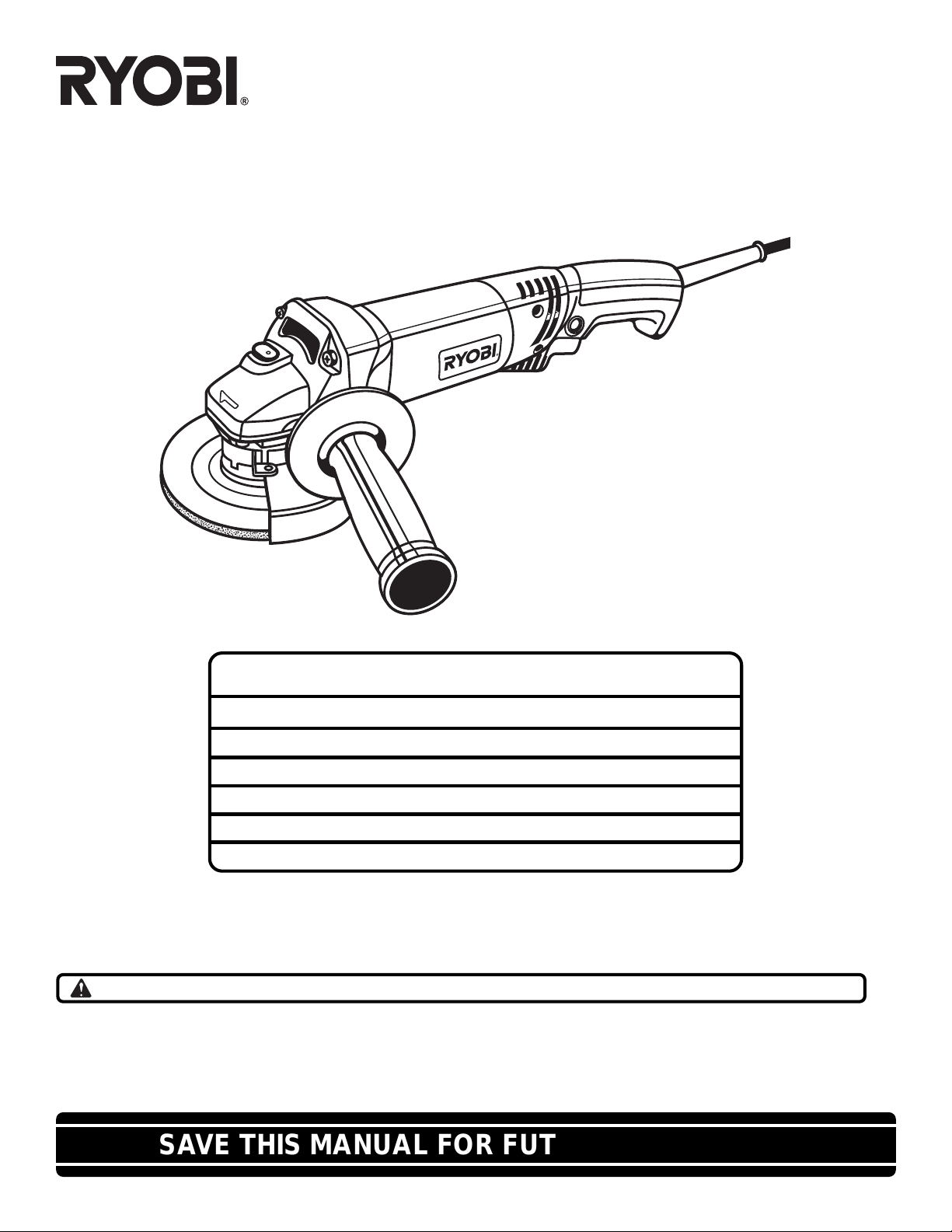
4-1/2 in. (115 mm) Angle Grinder
Model SGL1150 / Double Insulated
SPECIFICATIONS:
Grinding Wheel Capacity 4-1/2 in. (115 mm)
Spindle Thread Size 5/8-11 UNC
Rating 120 volts, 60 Hz, AC
No Load Speed 11,000 RPM
Amperes 6.6 Amperes
Net Weight 4.0 lbs. (1.8 kg.)
THANK YOU FOR BUYING A RYOBI ANGLE GRINDER.
Your new angle grinder has been engineered and manufactured to Ryobi's high standard for dependability, ease of operation,
and operator safety. Properly cared for, it will give you years of rugged, trouble-free performance.
CAUTION: Carefully read through this entire operator's manual before using your new angle grinder.
Pay close attention to the Rules for Safe Operation, Warnings, and Cautions. If you use your grinder properly and only for
what it is intended, you will enjoy years of safe, reliable service.
Please fill out and return the Warranty Registration Card so that we can be of future service to you.
Thank you again for buying Ryobi tools.
SAVE THIS MANUAL FOR FUTURE REFERENCE
Page 2
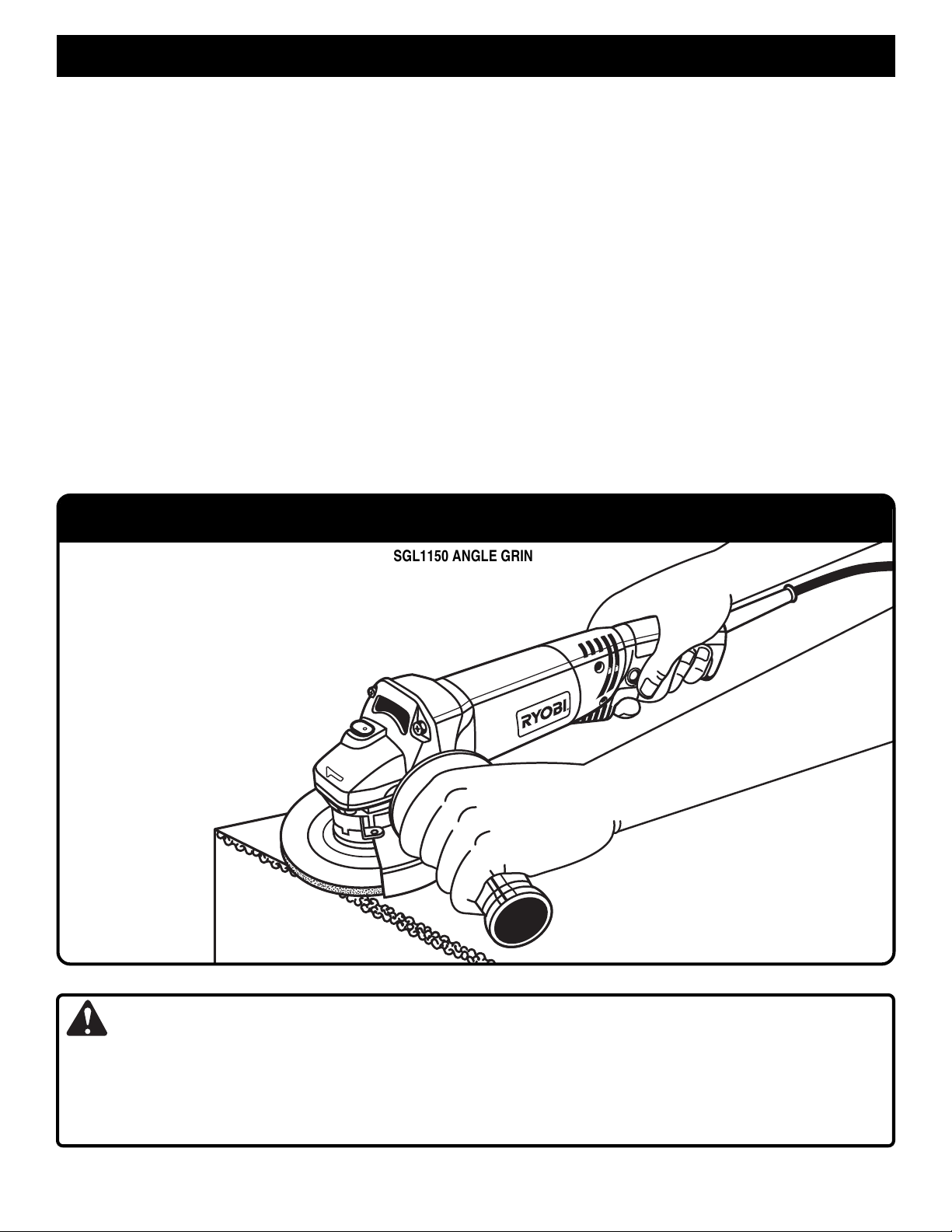
TABLE OF CONTENTS
a
a
a
a
a
a
a
aa
a
aa
aaa
a
a
a
■ Product Specifications .....................................................................................................1
■ Typical Application ...........................................................................................................2
■ General Safety Rules.......................................................................................................3
■ Rules For Safe Operation ................................................................................................4
■ Symbols ...........................................................................................................................5
■ Rules For Safe Operation For Grinders ...........................................................................6
■ Unpacking ........................................................................................................................6
■ Features...........................................................................................................................7
■ Adjustments ..................................................................................................................8-9
■ Operation ....................................................................................................................9-10
■ Maintenance .............................................................................................................11-12
■ Parts Ordering / Service.................................................................................................14
TYPICAL APPLICATION
SGL1150 ANGLE GRINDER
W ARNING:
To minimize the risk of eye injury, Always use eye protection which is marked to comply with ANSI Z87.1. Always use the
guard that accompanied the grinder. Comply with mounting and use instructions and warnings found in the manual for the
grinder and ANSI B7.1. Failure to heed these warnings can result in wheel breakage and serious personal injury. For more
information on ANSI Standards, contact the American National Standards Institute, Inc., 11 West 42nd Street, 13th Floor,
New York, NY 10036.
Page 2
Page 3

GENERAL SAFETY RULES
WARNING:
Read and understand all instructions. Failure to
follow all instructions listed below, may result in electric shock, fire and/or serious personal injury.
SAVE THESE INSTRUCTIONS
Work Area
■ Keep your work area clean and well lit. Cluttered
benches and dark areas invite accidents.
■ Do not operate power tools in explosive atmospheres, such as in the presence of flammable liquids, gases, or dust. Power tools create sparks which
may ignite the dust or fumes.
■ Keep bystanders, children, and visitors away while
operating a power tool. Distractions can cause you to
lose control.
Electrical Safety
■ Double insulated tools are equipped with a polarized plug (one blade is wider than the other.) This
plug will fit in a polarized outlet only one way. If the
plug does not fit fully in the outlet, reverse the plug.
If it still does not fit, contact a qualified electrician to
install a polarized outlet. Do not change the plug in
any way. Double insulation eliminates the need for
the three wire grounded power cord and grounded power
supply system.
■ Avoid body contact with grounded surfaces such as
pipes, radiators, ranges and refrigerators. There is
an increased risk of electric shock if your body is
grounded.
■ Do not expose power tools to rain or wet conditions.
Water entering a power tool will increase the risk of electric shock.
■ Do not abuse the cord. Never use the cord to carry
the tools or pull the plug from an outlet. Keep cord
away from heat, oil, sharp edges or moving parts.
Replace damaged cords immediately . Damaged cords
increase the risk of electric shock.
■ When operating a power tool outside, use an outdoor extension cord marked “W-A” or “W”. These
cords are rated for outdoor use and reduce the risk of
electric shock.
Personal Safety
■ Stay alert, watch what you are doing and use common sense when operating a power tool. Do not use
tool while tired or under the influence of drugs, alcohol, or medication. A moment of inattention while
operating power tools may result in serious personal injury.
■ Dress properly. Do not wear loose clothing or jewelry . Contain long hair . Keep your hair , clothing, and
gloves away from moving parts. Loose clothes, jew-
elry, or long hair can be caught in moving parts.
■ Avoid accidental starting. Be sure switch is off before plugging in. Carrying tools with your finger on the
switch or plugging in tools that have the switch on invites accidents.
■ Remove adjusting keys or wrenches before turning
the tool on. A wrench or a key that is left attached to a
rotating part of the tool may result in personal injury.
■ Do not overreach. Keep proper footing and balance
at all times. Proper footing and balance enables better
control of the tool in unexpected situations.
■ Use safety equipment. Always wear eye protection.
Dust mask, nonskid safety shoes, hard hat, or hearing
protection must be used for appropriate conditions.
Tool Use and Care
■ Use clamps or other practical way to secure and
support the workpiece to a stable platform. Holding
the work by hand or against your body is unstable and
may lead to loss of control.
■ Do not force tool. Use the correct tool for your application. The correct tool will do the job better and safer
at the rate for which it is designed.
■ Do not use tool if switch does not turn it on or off.
Any tool that cannot be controlled with the switch is dangerous and must be repaired.
■ Disconnect the plug from the power source before
making any adjustments, changing accessories, or
storing the tool. Such preventive safety measures re-
duce risk of starting the tool accidentally.
■ Store idle tools out of reach of children and other
untrained persons. Tools are dangerous in the hands
of untrained users.
■ Maintain tools with care. Keep cutting tools sharp
and clean. Properly maintained tools with sharp cutting
edges are less likely to bind and are easier to control.
■ Check for misalignment or binding of moving parts,
breakage of parts, and any other condition that may
affect the tool's operation. If damaged, have the tool
serviced before using. Many accidents are caused by
poorly maintained tools.
■ Use only accessories that are recommended by the
manufacturer for your model. Accessories that may
be suitable for one tool, may become hazardous when
used on another tool.
Service
■ Tool service must be performed only by qualified
repair personnel. Service or maintenance performed
by unqualified personnel could result in a risk of injury.
■ When servicing a tool, use only identical replacement parts. Follow instructions in Maintenance section of this manual. Use of unauthorized parts or fail-
ure to follow Maintenance Instructions may create a risk
of electric shock or injury.
Page 3
Page 4
RULES FOR SAFE OPERATION
Specific Safety Rules for Grinders
■ Always use proper guard with grinding wheel. A
guard protects operator from broken wheel fragments.
■ Accessories must be rated for at least the speed
recommended on the tool warning label. Wheels and
other accessories running over rated speed can fly apart
and cause injury.
■ Hold tool by insulated gripping surfaces when performing an operation where the tool may contact
hidden wiring or its own cord. Contact with a “live”
wire will make exposed metal parts of the tool “live” and
shock the operator.
Additional Rules for Safe Operation
■ Know your power tool. Read operator's manual
carefully. Learn its applications and limitations as
well as the specific potential hazards related to this
tool. Following this rule will reduce the risk of electric
shock, fire, or serious injury.
■ Always wear safety glasses. Everyday eyeglasses
have only impact resistant lenses; they are NOT
safety glasses. Following this rule will reduce the risk of
serious personal injury.
■ Protect your lungs. Wear a face or dust mask if the
operation is dusty. Following this rule will reduce the
risk of serious personal injury.
■ Protect your hearing. Wear hearing protection during extended periods of operation. Following this rule
will reduce the risk of serious personal injury.
■ Inspect tool cords periodically and if damaged,
have repaired at your nearest authorized service
center. Stay constantly aware of cord location. Fol-
lowing this rule will reduce the risk of electric shock or
fire.
■ Check damaged parts. Before further use of the tool,
a guard or other part that is damaged should be
carefully checked to determine that it will operate
properly and perform its intended function. Check
for alignment of moving parts, binding of moving
parts, breakage of parts, mounting, and any other
conditions that may affect its operation. A guard or
other part that is damaged should be properly repaired or replaced by an authorized service center.
Following this rule will reduce the risk of electric shock,
fire, or serious injury.
■ Do not abuse cord. Never carry tool by cord or yank
it to disconnect from receptacle. Keep cord from
heat, oil and sharp edges. Following this rule will
reduce the risk of electric shock or fire.
■ Make sure your extension cord is in good condition.
When using an extension cord, be sure to use one
heavy enough to carry the current your product will
draw. A wire gage size (A.W.G.) of at least 16 is
recommended for an extension cord 100 feet or less
in length. A cord exceeding 100 feet is not recommended. If in doubt, use the next heavier gage. The
smaller the gage number, the heavier the cord. An
undersized cord will cause a drop in line voltage resulting
in loss of power and overheating.
■ Inspect for and remove all foreign objects from
workpiece before grinding. Following this rule will
reduce the risk of serious personal injury.
■ Drugs, Alcohol, Medication. Do not operate tool
while under the influence of drugs, alcohol, or any
medication. Following this rule will reduce the risk of
electric shock, fire, or serious injury.
■ Keep hands away from grinding area. Following this
rule will reduce the risk of serious personal injury.
■ Save these instructions. Refer to them frequently
and use them to instruct others who may use this
tool. If you loan someone this tool, loan them these
instructions also.
WARNING:
Some dust created by power sanding, sawing, grinding,
drilling, and other construction activities contains
chemicals known to cause cancer, birth defects or
other reproductive harm. Some examples of these
chemicals are:
• lead from lead-based paints,
• crystalline silica from bricks and cement and other
masonry products, and
• arsenic and chromium from chemically-treated
lumber.
Your risk from these exposures varies, depending on
how often you do this type of work. To reduce your
exposure to these chemicals: work in a well ventilated
area, and work with approved safety equipment, such
as those dust masks that are specially designed to filter
out microscopic particles.
SAVE THESE INSTRUCTIONS
Page 4
Page 5
SYMBOLS
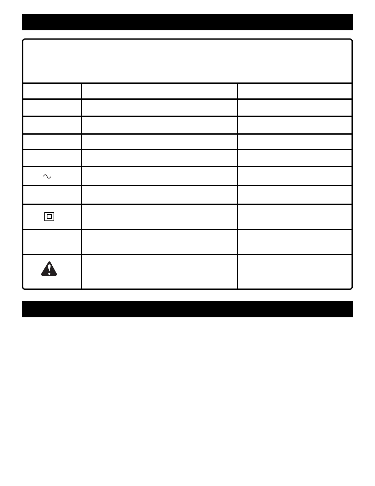
Important: Some of the following symbols may be used on your tool. Please study them and learn their meaning.
Proper interpretation of these symbols will allow you to operate the tool better and safer.
SYMBOL NAME DESIGNATION/EXPLANATION
V Volts Voltage
A Amperes Current
Hz Hertz Frequency (cycles per second)
W Watt Power
min Minutes Time
Alternating Current Type or a characteristic of current
n
0
.../min Revolutions or Reciprocation Per Minute Revolutions, strokes,
No Load Speed Rotational speed, at no load
Class II Construction Designates Double Insulated
Construction tools
surface speed, orbits etc. per minute
Safety Alert Symbol Indicates danger, warning or caution.
It means attention!!! Your safety is
involved.
FEATURES
DEFINITIONS
A) DANGER: Failure to obey a safety warning will result in serious injury to yourself or to others. Always
follow the safety precautions to reduce the risk of fire, electric shock and personal injury.
B) WARNING: Failure to obey a safety warning can result in serious injury to yourself or to others. Always
follow the safety precautions to reduce the risk of fire, electric shock and personal injury.
C) CAUTION: Failure to obey a safety warning may result in property damage or personal injury to yourself
or to others. Always follow the safety precautions to reduce the risk of fire, electric shock and personal
injury.
D) NOTE: Advises you of information or instructions vital to the operation or maintenance of the equipment.
Page 5
Page 6
RULES FOR SAFE OPERATION FOR GRINDERS
■ Grinding wheel and guard must be securely
attached as described in this operating manual
before connecting the grinder to a power source.
■ Grinding wheels must be stored in a dry place.
■ Before attaching the grinding wheel, inspect it for
visible defects. If cracked, chipped, or warped, do
not install it.
■ Do not overtighten the clamp nut on the grinding
wheel. Excessive tightening can cause the wheel
to crack during operation
■ Make sure that the guard is in good condition and
securely installed before operating grinder.
■ Do not clamp the grinder in a vise or use as a fixed
grinder.
■ Never turn on the grinder with the grinding wheel
or any rotating parts touching the workpiece.
■ Use only grinding wheels in compliance with ANSI
standard B7.1 and rated greater than 11,000 rpm.
■ Do not use the grinder if the disc flange or clamp
nut is missing or if the spindle is bent.
■ Always hold the grinder securely with two hands
while working and at all times when it is running.
■ Never cover the air vents in the motor housing
with your hands while operating the grinder.
■ Hold the tool away from your body while it is
running. Keep your hands away from the abrasive
attachments.
■ Dust and waste materials should not be allowed to
build up in the workshop. Hot metal sparks could
start a fire.
■ Do not remove the soft paper in the center of the
grinding wheel. NOTE: If this paper has been
previously removed, insert some soft rubber or
paper between the grinding wheel and disc flange.
■ Do not enlarge or alter the center hole of the
grinding wheel as this could result in breaking it.
■ Use only the normal grinder surface. Never use
the side or upper surfaces for cutting.
■ KEEP THE TOOL AND ITS HANDLE DRY,
CLEAN, AND FREE FROM OIL AND GREASE.
Always use a clean cloth when cleaning. Never
use brake fluids, gasoline, petroleum-based
products, or any strong solvents to clean your tool.
UNPACKING
With the exception of the side handle and grinding wheel,
your angle grinder has been shipped completely assembled.
■ Carefully remove the grinder and accessories from the
box. Make sure that all items listed in the packing list are
included.
■ Inspect grinder carefully to make sure no breakage or
damage has occurred during shipping.
■ If any parts are damaged or missing, contact your nearest
Ryobi dealer to obtain replacement parts before
attempting to operate grinder.
■ Do not discard the packing material until you have
carefully inspected and satisfactorily operated grinder.
WARNING:
The operation of any grinder can result in foreign objects being thrown into your eyes,
which can result in severe eye damage. Before beginning power tool operation, always
wear safety goggles or safety glasses with side shields and a full face shield when
needed. We recommend Wide Vision Safety Mask for use over eyeglasses or standard
safety glasses with side shields.
PACKING LIST
Angle Grinder With Guard
Grinding Wheel
Side Handle
Wrench
Operator's Manual
Warranty Registration Card
WARNING:
If any parts are missing, do not operate your grinder until
the missing parts are replaced. Failure to do so could
result in possible serious personal injury.
Page 6
Page 7
a
a
a
a
a
a
a
aa
a
aa
aaa
a
a
a
a
a
a
a
aa
FEATURES
KNOW YOUR ANGLE GRINDER
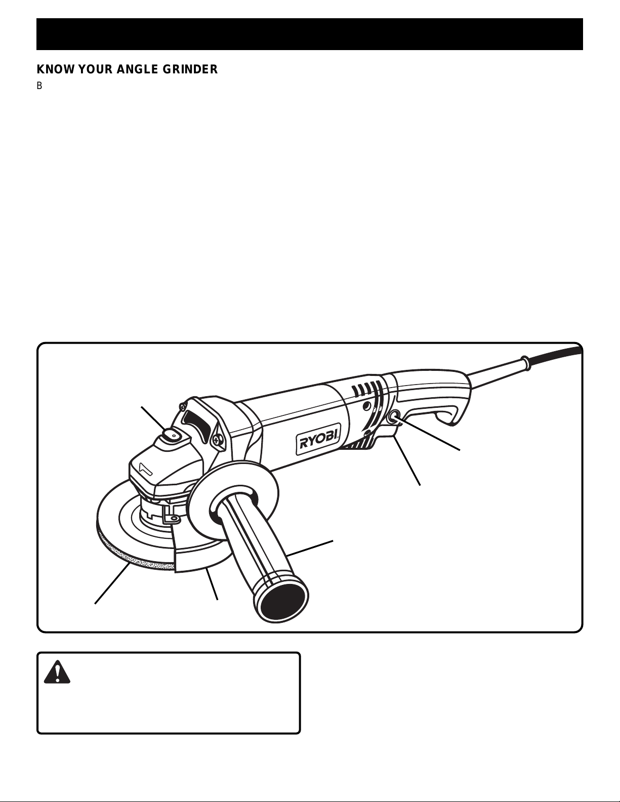
Before attempting to use your grinder, familiarize yourself
with all operating features and safety requirements.
See Figure 1.
Make sure all grinding wheels and recommended accessories
are in accordance with listed specifications for this tool. For
example, do not use grinding wheels that are rated at less
than 11,000 RPM.
HEAVY DUTY MOTOR
Your Ryobi SGL1150 Angle Grinder has a powerful motor,
with sufficient power to handle tough grinding jobs that
require heavy duty performance.
GUARD
A protective guard has been provided on your grinder. It
deflects sparks and metal chips during use.
TRIGGER SWITCH WITH LOCK-ON FEATURE
Your grinder has a conveniently located trigger switch. It also
has a lock-on feature that allows the grinder to be locked in
the on position when continuous operation for extended
periods of time is required.
SPINDLE LOCK BUTTON
The spindle lock button secures the spindle so that only one
wrench is needed to change the grinding wheel.
SIDE HANDLE
The side handle provided, stabilizes your grinder and must
be used during all grinding operations. In addition to
maintaining safe control during use, the side handle also
provides convenient ease of operation for the operator.
APPLICATIONS
(Use only for the purposes listed below)
■ Grinding metals.
■ Preparing surfaces to be welded.
■ Grinding welds.
SPINDLE
LOCK BUTTON
LOCK-ON
BUTTON
TRIGGER SWITCH
SIDE HANDLE
GRINDING WHEEL
WARNING:
Do not allow familiarity with your grinder to make you
careless. Remember that a careless fraction of a second
is sufficient to inflict severe injury.
GUARD
Fig. 1
ELECTRICAL CONNECTION
Your grinder has a precision built electric motor. It should
be connected to a power supply that is 120 volts, 60 Hz,
AC only (normal household current). Do not operate
this tool on direct current (DC). A substantial voltage drop
will cause a loss of power and the motor will overheat. If
your tool does not operate when plugged into an outlet,
double-check the power supply.
Page 7
Page 8
WARNING:
ADJUSTMENTS
Your grinder should never be connected to power supply
when you are assembling parts, making adjustments,
installing or removing grinding wheels, or when not in use.
Disconnecting your grinder will prevent accidental starting
that could cause serious injury.
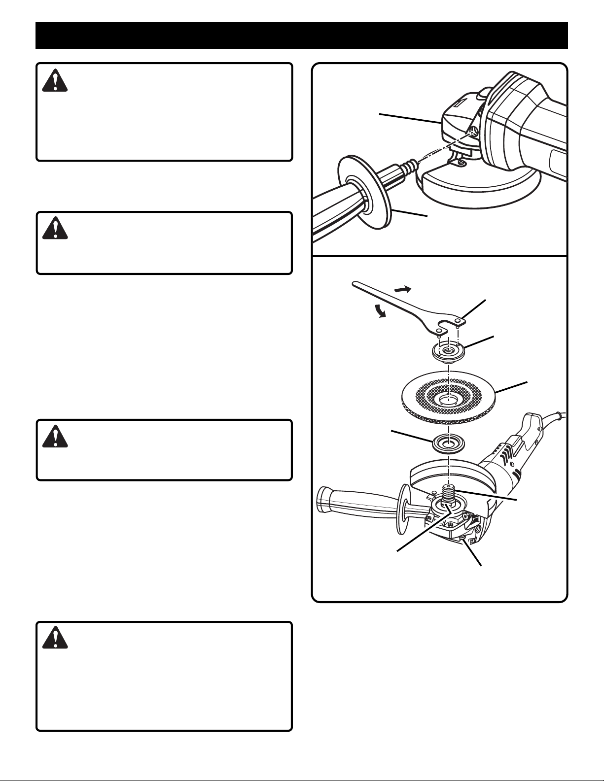
INSTALLING THE SIDE HANDLE
See Figure 2.
■ UNPLUG YOUR GRINDER.
WARNING:
Failure to unplug your grinder could result in accidental
starting causing serious injury.
■ Install the side handle by screwing it into the side of the
gear housing.
NOTE: The handle can be installed on either the left or
right side of the grinder, depending on operator preference. It must always be used to prevent loss of control
and possible serious injury.
■ Tighten side handle securely.
INSTALLING THE GRINDING WHEEL
See Figure 3.
■ UNPLUG YOUR GRINDER.
WARNING:
GEAR
HOUSING
TO
LOOSEN
DISC
FLANGE
SIDE
HANDLE
Fig. 2
TO
TIGHTEN
WRENCH
CLAMP
NUT
GRINDING
WHEEL
Failure to unplug your grinder could result in accidental
starting causing serious injury.
■ Your grinder is shipped with the disc flange and clamp
nut attached to the spindle.
■ Depress spindle lock button and rotate clamp nut until
spindle locks.
■ Loosen and remove clamp nut from spindle. Do not
remove disc flange.
■ Make sure flats on the bottom of disc flange are engaged
with flats on spindle.
■ Place the grinding wheel over the spindle with the
concave side of the wheel facing up.
WARNING:
Always install grinding wheel with the depressed center
against the disc flange as shown in figure 3. Failure to do
so will cause the grinding wheel to crack when tightening
the clamp nut. This could result in serious personal injury
because of loose particles breaking off and being thrown
from the grinder.
SPINDLE
FLAT(S)
■ Thread the clamp nut on the spindle with the flat side of
the nut facing up. Fit the raised, small diameter portion
of the clamp nut into the hole in the grinding wheel and
finger tighten.
■ Depress the spindle lock button and rotate the wheel
clockwise until the spindle locks in position.
■ Securely tighten the clamp nut with the wrench provided.
SPINDLE
LOCK BUTTON
Fig. 3
Page 8
Page 9
ADJUSTMENTS
WARNING:
Before connecting your grinder to power supply, always
check to be sure switch is not in lock-on position. Failure
to do so could result in accidental starting of your grinder
resulting in possible serious injury.
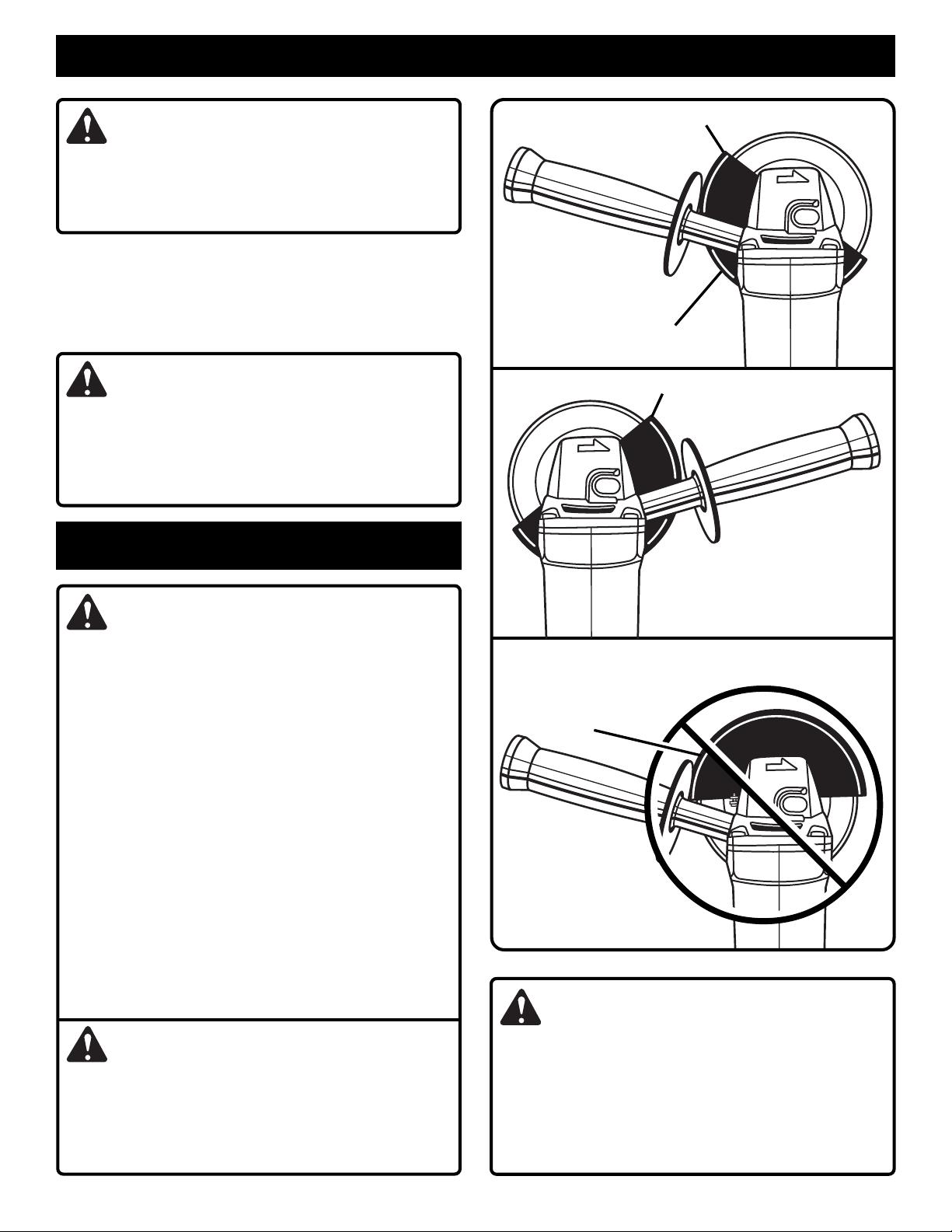
GUARD LOCATION
The guard on your grinder should be correctly installed
depending on which side the handle is mounted. Never use
your grinder without the guard correctly in place. Figures 4-6 show correct and incorrect locations of the guard.
WARNING:
Never place the guard so that it is on front of the grinder as
shown in figure 6. This could result in serious injury because
sparks and loose particles thrown from the grinding wheel
would be directed toward the operator. Always place the
guard in the correct location as shown in figures 4 and 5.
OPERATION
A
CORRECT
LOCATION OF GUARD IS
BETWEEN POINTS A AND B
B
Fig. 4
WARNING:
■ Always wear safety glasses and keep guard in place
when grinding.
■ Hot metal sparks from metal grinding can cause a fire.
Avoid spark contact with flammable materials such as
saw dust, or clothing.
■ Grinding wheels must be free of fissures and cracks.
Fissures and cracks can cause a grinding wheel to
shatter, resulting in possible serious injury.
Thoroughly inspect a new grinding wheel before it is
installed on the grinder:
1. Use a wooden hammer for the inspection.
2. Using the hammer, lightly tap all around the wheel,
carefully listening to the resulting sounds.
3. Any places with fissures or cracks will result in a
different sound.
Do not use a wheel containing fissures or cracks.
When installing a new grinding wheel, a no load
revolution test of approximately one minute must be
carried out with the grinding wheel facing a safe
direction, i.e. away from people or objects.
DANGER:
Never attach a wood cutting or carving blade of any
type to this angle grinder. It is only designed for
grinding metal. Use for any other purpose is not
recommended and creates a hazard which will result in
serious injury.
Fig. 5
INCORRECT
LOCATION OF GUARD
Fig. 6
WARNING:
Do not attempt to operate this tool until you have read
thoroughly and understand completely all instructions,
safety rules, etc. contained in this manual. Failure to
comply can result in accidents involving fire, electric
shock, or serious personal injury. Save operator's manual
and review frequently for continuing safe operation, and
instructing others who may use this tool.
Page 9
Page 10
OPERATION
CAUTION:
Never cover air vents. They must always be open for
proper motor cooling.
SWITCH
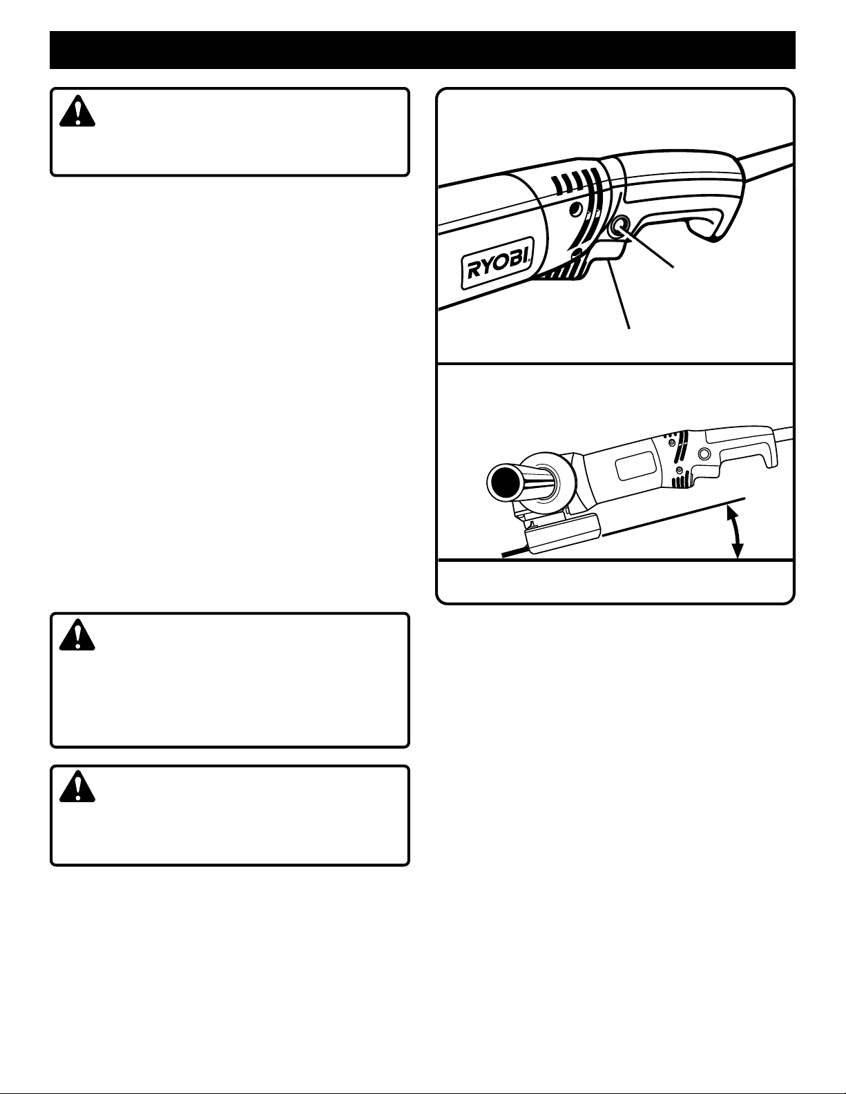
See Figure 7.
To turn your grinder ON, depress the switch trigger. Release
the switch trigger to turn your grinder OFF.
LOCK-ON FEATURE
See Figure 7.
Your grinder has a lock-on feature that is convenient when
continuous operation for extended periods of time is required.
To lock-on, depress the trigger switch, push in the lock button
located on the side of the handle, then while holding the lock
button pushed in, release the trigger. To release the lock,
depress the trigger switch and release it.
GRINDING
See Figure 8.
Always carefully select and use grinding wheels that are
recommended for the material to be ground. Make sure that
the minimum operating speed of the grinding wheel selected
is not less than 11,000 rpm. The grinding wheel provided with
your grinder is suitable for grinding welds, preparing surfaces to be welded, grinding structural steel, and grinding
stainless steel.
Secure all work before beginning a grinding operation.
Secure small workpieces in a vise or clamp to a workbench.
DANGER:
Never use your grinder with the guard removed. It has
been designed for use only with the guard installed.
Attempting to use grinder with guard removed will result
in loose particles being thrown against the operator
resulting in serious personal injury.
WARNING:
Never use your grinder without wearing eye protection.
Following this rule will reduce the risk of serious personal
injury.
The key to efficient operation begins by controlling the
pressure and surface contact between the grinding wheel
and workpiece. Flat surfaces are ground at an acute angle,
normally between 5 to 15 degrees.
For maximum control, hold the grinder in front and away from
you with both hands, keeping the grinding wheel clear of the
LOCK-ON
BUTTON
TRIGGER SWITCH
5° TO 15°
workpiece. Start your grinder and let the motor and grinding
wheel build up to full speed. Gradually lower grinder until the
grinding wheel contacts the workpiece.
For best results keep the grinder tilted at an angle from 5 to
15 degrees and continuously moving at a steady, consistent
pace. Move the grinder back and forth or up and down over
the work area. Keep the grinder moving so that an excessive
amount of material is not removed from one area. If the
grinder is held in one spot too long, it will gouge and cut
grooves in the workpiece. If the grinder is held at too sharp
an angle, it will also gouge the workpiece because of
concentration of pressure on a small area.
Use just enough pressure to keep the grinder from chattering
or bouncing. Heavy pressure will decrease its speed and put
a strain on the motor. Normally the weight of the tool alone
is adequate for most grinding jobs. Use light pressure when
grinding jagged edges or loose bolts where there is the
potential for the grinder to snag on the metal edge.
Lift the grinder away from the workpiece before turning your
grinder off.
Fig. 7
Fig. 8
Page 10
Page 11
MAINTENANCE
WARNING:
When servicing use only identical Ryobi replacement parts. Use of any other parts may create a hazard or cause product
damage.
GUARD REPLACEMENT
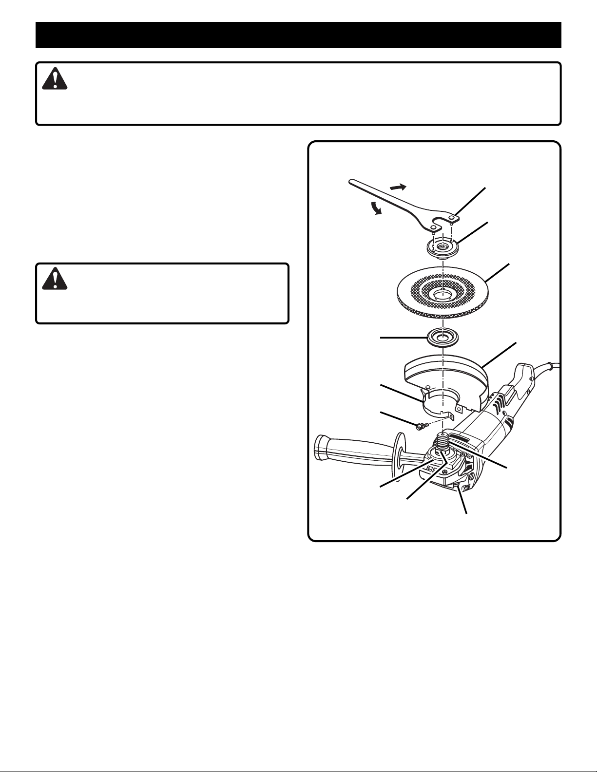
See Figure 9.
After extended use, the guard may become worn and need
adjustments or replacing. If you drop your grinder and
damage the guard it may also be necessary for you to
replace it.
PROCEED AS FOLLOWS WHEN REPLACEMENT IS
REQUIRED:
■ UNPLUG YOUR GRINDER.
TO
LOOSEN
TO
TIGHTEN
WRENCH
CLAMP
NUT
GRINDING
WHEEL
WARNING:
Failure to unplug your grinder could result in accidental
starting causing serious injury.
■ Remove and reassemble parts as shown in figure 9.
■ Depress spindle lock button and rotate clamp nut until
spindle locks.
■ Using the wrench provided, loosen and remove clamp
nut from spindle.
■ Remove grinding wheel and disc flange.
■ Using a screwdriver, loosen the clamp screw until the
guard can be adjusted or removed.
■ If you are making adjustments, rotate the guard to its
correct position as shown in figures 4, 5, and 9, then
retighten clamp screw securely. Never use your grinder
without the guard in place and properly adjusted.
See Figures 4 and 5.
■ If you are replacing the guard, loosen the clamp screw
until the guard and clamp can be removed from the
bearing cap.
■ Place the new guard and clamp on the shoulder of the
bearing cap.
NOTE: If the new guard and clamp will not fit, loosen the
clamp screw until they slide over the bearing cap.
■ Rotate guard to the correct position as shown in figure 9.
■ Tighten clamp screw securely.
■ Reassemble disc flange, grinding wheel, and clamp nut.
Refer to "INSTALLING THE GRINDING WHEEL" instructions on page 8.
■ Securely tighten the clamp nut with the wrench provided.
See Figure 9.
DISC
FLANGE
CLAMP
CLAMP
SCREW
BEARING CAP
FLAT(S)
SPINDLE
LOCK BUTTON
GUARD
SPINDLE
Fig. 9
Page 11
Page 12
MAINTENANCE
GENERAL
Avoid using solvents when cleaning plastic parts. Most plastics
are susceptible to damage from various types of commercial
solvents and may be damaged by their use. Use clean cloths
to remove dirt, carbon dust, etc.
WARNING:
Do not at any time let brake fluids, gasoline, petroleumbased products, penetrating oils, etc. come in contact
with plastic parts. They contain chemicals that can
damage, weaken, or destroy plastic.
WARNING:
Always wear safety goggles or safety glasses with side
shields during power tool operation or when blowing dust.
If operation is dusty, also wear a dust mask.
LUBRICATION
All of the bearings in this tool are lubricated with a sufficient
amount of high grade lubricant for the life of the unit under
normal operating conditions. Therefore, no further lubrication
is required.
DOUBLE INSULATION
Double insulation is a concept in safety, in electric power
tools, which eliminates the need for the usual three-wire
grounded power cord. All exposed metal parts are isolated
from the internal metal motor components with protecting
insulation. Double insulated tools do not need to be grounded.
WARNING:
The double insulated system is intended to protect the
user from shock resulting from a break in the tool's
internal wiring. Observe all normal safety precautions
related to avoiding electrical shock.
IMPORTANT
Servicing of a tool with double insulation requires extreme
care and knowledge of the system and should be performed
only by a qualified service technician. For service we suggest
you return the tool to your nearest RYOBI AUTHORIZED
SERVICE CENTER for repair. When servicing use only
identical Ryobi replacement parts.
Page 12
Page 13
OPERATOR'S MANUAL
4-1/2 in. (115 mm) Angle Grinder
Model SGL1 150 / Double Insulated
EXTENSION CORD CAUTION
When using a power tool at a considerable distance from a power
source, be sure to use an extension cord that has the capacity to
handle the current the tool will draw. An undersized cord will cause
a drop in line voltage, resulting in overheating and loss of power.
Use the chart to determine the minimum wire size required in an
extension cord. Only round jacketed cords should be used.
When working with a tool outdoors, use an extension cord that is
designed for outside use. This is indicated by the letters "WA" on
the cord's jacket.
Before using any extension cord, inspect it for loose or exposed
wires and cut or worn insulation.
• SERVICE
Now that you have purchased your tool, should a need ever exist for repair parts or service,
simply contact your nearest Ryobi Authorized Service Center. Be sure to provide all
pertinent facts when you call or visit. Please call 1-800-525-2579 for your nearest Ryobi
Authorized Service Center. You can also check our web site at www.ryobitools.com for a
complete list of Authorized Service Centers.
**Ampere rating
(on tool data plate) 0-2.0 2.1-3.4 3.5-5.0 5.1-7.0 7.1-12.0 12.1-16.0
Cord Length Wire Size (A.W.G.)
25' 161616161414
50' 161616141412
100' 16 16 14 12 10 —
CAUTION: Keep the extension cord clear of the working
area. Position the cord so that it will not get caught on workpiece,
tools, or other obstructions while you are working with a power
tool.
**Used on 12 gauge - 20 amp circuit.
• MODEL NO.
The model number of your tool will be found on a plate attached to the motor housing.
Please record the model number and serial number in the space provided below.
972000-700
6-01
• MODEL NUMBER SGL1150
• SERIAL NUMBER
RYOBI TECHNOLOGIES, INC.
1428 Pearman Dairy Road Anderson SC 29625
Post Office Box 1207 Anderson SC 29622
Phone 1-800-525-2579
www.ryobitools.com
 Loading...