

Page 1
OPERATOR’S MANUAL
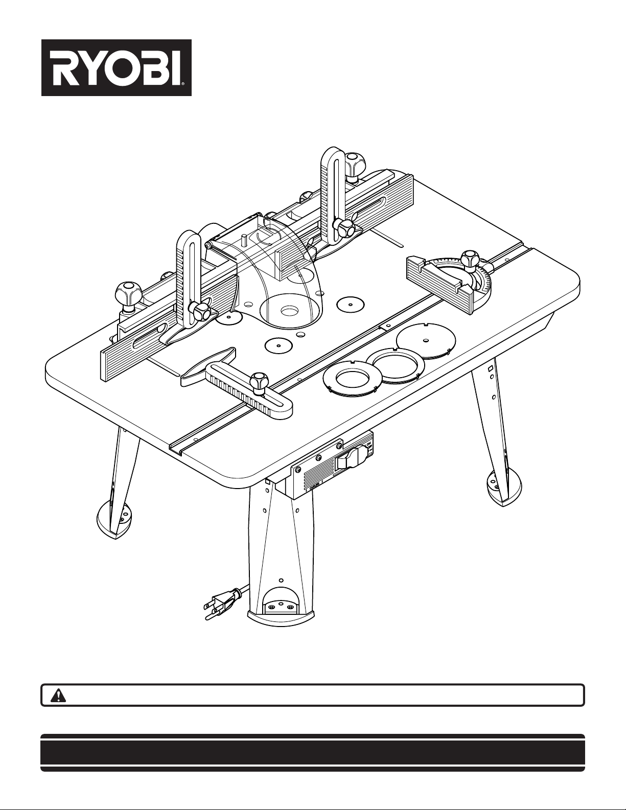
ROUTER TABLE RT501W
Power tools and some accessories Not included.
Your new router table has been engineered and manufactured to Ryobi's high standard for dependability, ease of
operation, and operator safety. Properly cared for, it will give you years of rugged, trouble-free performance.
WARNING: To reduce the risk of injury, the user must read and understand the operator’s manual.
Thank you for purchasing a Ryobi router table.
SAVE THIS MANUAL FOR FUTURE REFERENCE
Page 2
TABLE OF CONTENTS
Introduction . . . . . . . . . . . . . . . . . . . . . . . . . . . . . . . . . . . . . . . . . . . . . . . . . . . . . . . . . . . . . . . . . . . . . . . . . . . . . . .2
Rules for Safe Operation . . . . . . . . . . . . . . . . . . . . . . . . . . . . . . . . . . . . . . . . . . . . . . . . . . . . . . . . . . . . . . . . . . .3-4
Unpacking and checking contents . . . . . . . . . . . . . . . . . . . . . . . . . . . . . . . . . . . . . . . . . . . . . . . . . . . . . . . . . . . . . .4
Features and Specifications . . . . . . . . . . . . . . . . . . . . . . . . . . . . . . . . . . . . . . . . . . . . . . . . . . . . . . . . . . . . . . . . . .5
Package contents and hardware legend . . . . . . . . . . . . . . . . . . . . . . . . . . . . . . . . . . . . . . . . . . . . . . . . . . . . . . . .6-9
Assembly . . . . . . . . . . . . . . . . . . . . . . . . . . . . . . . . . . . . . . . . . . . . . . . . . . . . . . . . . . . . . . . . . . . . . . . . . . . . .10-13
Mounting the router . . . . . . . . . . . . . . . . . . . . . . . . . . . . . . . . . . . . . . . . . . . . . . . . . . . . . . . . . . . . . . . . . . . . .14-17
Switch box . . . . . . . . . . . . . . . . . . . . . . . . . . . . . . . . . . . . . . . . . . . . . . . . . . . . . . . . . . . . . . . . . . . . . . . . . . . .18-20
Operation . . . . . . . . . . . . . . . . . . . . . . . . . . . . . . . . . . . . . . . . . . . . . . . . . . . . . . . . . . . . . . . . . . . . . . . . . . . . .20-23
Accessories . . . . . . . . . . . . . . . . . . . . . . . . . . . . . . . . . . . . . . . . . . . . . . . . . . . . . . . . . . . . . . . . . . . . . . . . . . . . .24
Securing the router table . . . . . . . . . . . . . . . . . . . . . . . . . . . . . . . . . . . . . . . . . . . . . . . . . . . . . . . . . . . . . . . . . . . .24
Repair parts . . . . . . . . . . . . . . . . . . . . . . . . . . . . . . . . . . . . . . . . . . . . . . . . . . . . . . . . . . . . . . . . . . . . . . . . . . .25-26
INTRODUCTION
Your router table has many features for making the use of
a router more pleasant and enjoyable.
Safety, performance, and dependability have been given
top priority in the design of this router table making it easy
to maintain and operate.
WARNING:
Do not attempt to use this product until you have read
thoroughly and completely understand the operator’s
manual. Pay close attention to the safety rules,
including Dangers, Warnings, and Cautions. If you
use your router table properly and only for what it is
intended, you will enjoy years of safe, reliable service.
The operation of any power tool can result in foreign objects being thrown into your eyes, which
can result in severe eye damage. Before beginning tool operation, always wear safety goggles
or safety glasses with side shields and a full face shield when needed. We recommend Wide
Vision Safety Mask for use over eyeglasses or standard safety glasses with side shields.
Always wear eye protection which is marked to comply with ANSI Z87.1.
Look for this symbol to point out important safety
precautions. It means attention!!! Your safety is involved.
2
Page 3

RULES FOR SAFE OPERATION
WARNING:
Means that failure to follow this safety statement may
result in extensive product damage, serious personal
injury, or death.
WARNING:
Read all safety instructions before using
Read the owner's manual carefully. Learn its applications and limitations as well as the specific potential
hazards.
Ground all tools (unless double insulated)
If tool is equipped with an approved 3-conductor cord
and a 3-prong grounding type plug to fit the proper
grounding type receptacle, the green conductor in the
cord is the grounding wire. NEVER connect the green
wire to a live terminal.
Keep away from hazardous materials
Normal sparking of the motor could ignite fumes,
flammable liquids, or combustibles.
Protect yourself against personal injury
DO NOT operate any tool while under the influence of
drugs, alcohol, or any medication.
Dress for safety
Do not wear loose clothing, gloves, neckties, or jewelry,
as these items can get caught and draw you into
moving parts. ALWAYS wear non-slip footwear. Tie back
long hair. Roll long sleeves above the elbow.
Avoid accidental starting
Make sure all switches are in "OFF" position before
plugging in.
Never stand on tool
Serious injury could occur if the tool is tipped or if the
cutting tool is accidentally contacted. DO NOT store
materials above or near the tool, making it necessary to
stand on the tool to reach them.
Protect and use suitable cords
NEVER carry tool by cord or yank it to disconnect from
receptacle. Protect cord from heat, oil and sharp edges.
For outdoor operation, use extension cords intended for
outdoor use.
Avoid a dangerous environment
DO NOT use power tools in damp or wet locations or
expose them to rain. Keep work area well lit and
provide an adequate surrounding work space.
Check direction of feed
Feed workpiece against the router bit’s direction of
rotation.
Check damaged parts
Before further use of the tool, a guard or other part that
is damaged should be carefully checked to ensure that
it will operate properly and perform its intended
function. Check for alignment of moving parts, binding
of moving parts, broken parts, mounting and any other
conditions that may affect its operation. A guard or other
part that is damaged should be properly repaired or
replaced.
Never leave tool running unattended
Turn power off. Do not leave tool until it comes to a
complete stop.
Secure router table
DO NOT attempt to use your router table unless it is
fastened firmly to your workbench or floor.
Disconnect tools before servicing
When changing bits, make sure router is unplugged.
Keep guards in place
Be sure guards are in working order, properly adjusted,
and aligned.
KEEP HANDS AWAY FROM CUTTING AREA
3
Page 4
RULES FOR SAFE OPERATION
CAUTION:
Means that failure to follow this safety statement may
result in minor or moderate personal injury, or property
or equipment damage.
CAUTION:
Store properly
Do not store router table outdoors or in a damp location.
Keep work area clean
ALWAYS keep your work area clean, uncluttered, and
well lit. DO NOT work on or place router table legs on
floor surfaces that are slippery from sawdust, oil, water,
or wax.
Do not force the tool
Do not force tool or attachment to do a job for which it
was not designed. It will do the job better and more
safely at the rate for which it was designed.
Use clamps or a vise to hold work when practical
Using clamps or a vise to hold work is safer than using
your hand. It also frees both hands to operate the tool.
Do not overreach
Keep proper footing and balance at all times.
Maintain tools with care
Keep tools sharp and clean for best and safest performance. Follow instructions for lubricating and changing
accessories.
Use recommended accessories
Consult this manual for recommended accessories.
Follow the instructions that accompany the accessories.
The use of improper accessories may cause hazards.
Remove adjusting keys and wrenches
Form the habit of checking to see that keys and
adjusting wrenches are removed from the tool before
turning it on.
Ensure safety of others
Keep visitors and children a safe distance away from
the work area, especially when operating a power tool.
Visitors should wear the same safety equipment as the
operator.
SAVE THESE INSTRUCTIONS
UNPACKING AND CHECKING CONTENTS
Separate all parts from packaging materials and check
each item against the package contents listed in this
manual, found on pages 6-9.
If any parts are damaged or missing, please call
(800) 525-2579 for assistance.
Your RYOBI®router table is shipped complete in one
carton. Make sure all items are accounted for before
discarding any of the packing materials.
4
Page 5
FEATURES AND SPECIFICATIONS
Table weight. . . . . . . . . . . . . . . . . . . . . . . . . . . . . . . . . . . . . . . . . . . . . . . . . . . . . . . . . . . . . . . . . . . . . . . . . . .27,5 lbs.
Table work space. . . . . . . . . . . . . . . . . . . . . . . . . . . . . . . . . . . . . . . . . . . . . . . . . . . . . . . . . . . . . . . .567 square inches
Dimensions . . . . . . . . . . . . . . . . . . . . . . . . . . . . . . . . . . . . . . . . . . . . . . . . . . . . . . . . . . . . . . . .31-1/2"L 18"W x x 14"H
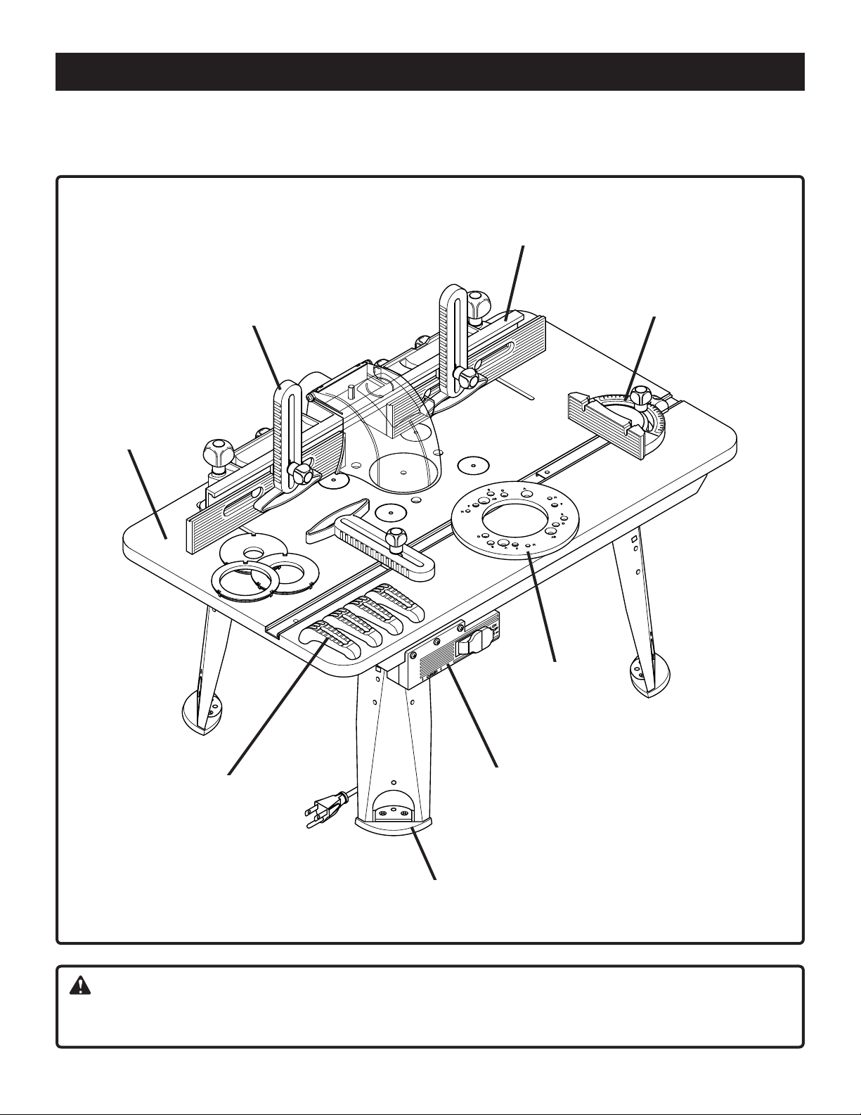
ROUTER TABLE features include:
Multi-position fence
High contrast
white tabletop
Multi-adjustable
featherboards
Easy to read
miter guide
Universal
router adapter
plate
Universal router
clamping system
Accessible clamping position
Twin receptacle
electrical switch
Fig. 1
WARNING:
Do not attempt to modify this tool or create accessories not recommended for use with this tool. Any such alteration
or modification is misuse and could result in a hazardous condition leading to possible serious personal injury.
5
Page 6
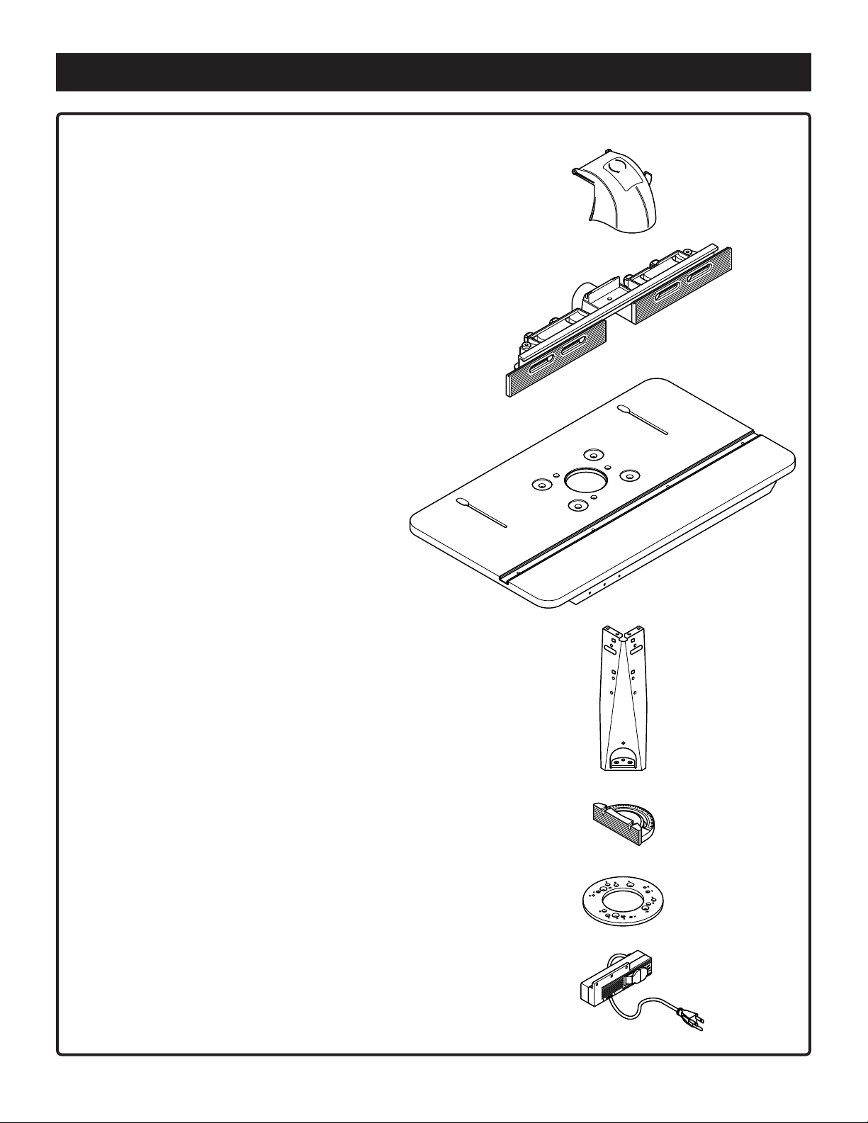
PACKAGE CONTENTS AND HARDWARE LEGEND
ITEM DESCRIPTION QTY.
A Safety shield 1 A
B Fence 1 B
CTabletop 1 C
D Leg 4 D
E Miter guide 1 E
F Adapter plate 1 F
G Switch box 1 G
6
Page 7

PACKAGE CONTENTS AND HARDWARE LEGEND
ITEM DESCRIPTION QTY.
H Featherboard 3 H
J Sliding block 3 J
K Cap for table top 4 K
LTabletop insert, 1 L
MTabletop insert, 1 M
small hole
NTabletop insert, 1
medium hole
PTabletop insert, 1
large hole
Q Swivel piece 4
R Clamp 4 R
S Knob 8 S
N
P
Q
T Knob screw 2 T
7
Page 8
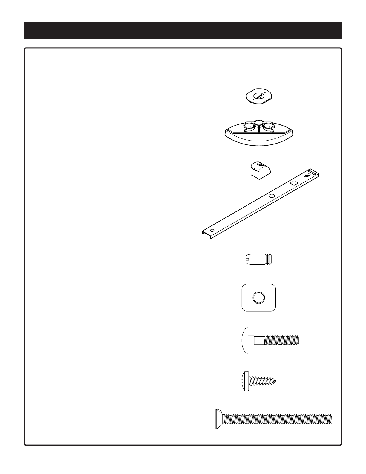
PACKAGE CONTENTS AND HARDWARE LEGEND (Continued)
Note: Hardware parts shown (screws, nuts, washers) are actual size.
ITEM DESCRIPTION QTY.
U Flange nut 4 U
V Footpad 4 V
WMiter pointer 1 W
X Miter bar 1 X
Y Locating pin 3 Y
Z Flat nut (M 6) 2 Z
AA Carriage bolt 1 AA
(M 6 x 30)
AB Pan head screw 16
(5 x 16)
AC Countersink screw 4
with nose (M 6 x 65)
AB
AC
8
Page 9
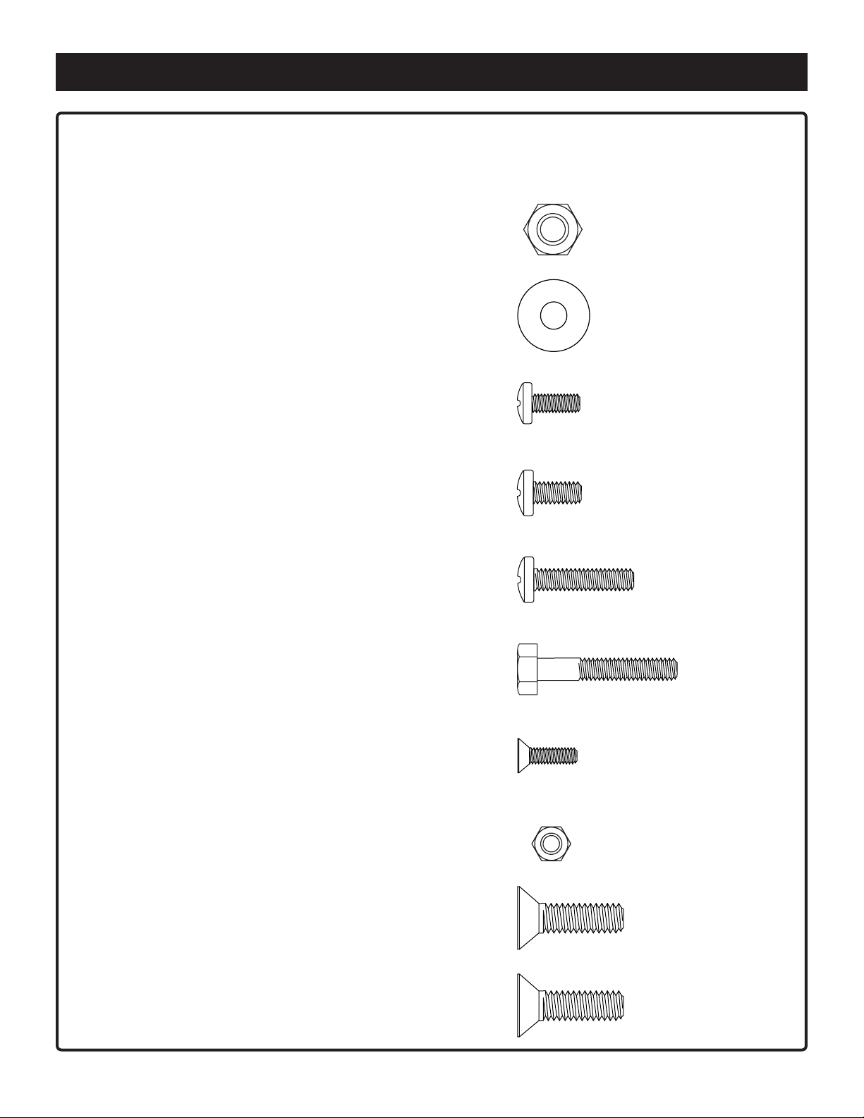
PACKAGE CONTENTS AND HARDWARE LEGEND (Continued)
Note: Hardware parts shown (screws, nuts, washers) are actual size.
ITEM DESCRIPTION QTY.
AD Hex nut (M 6) 4 AD
AE Washer (6.4 DIN 9021) 14 AE
AF Self tapping pan head screw 5 AF
(M 5 x 12)
AG Pan head screw 3
(M 6 x 12)
AH Pan head screw 2
(M 6 x 25)
AJ Hex head bolt 3
(M 6 x 35)
AK Countersink screw 8
(M 4 x 12)
AL Hex nut (M 4) 8
AG
AH
AJ
AK
AL
AM Countersink screw 3 AM
(5/16" - 18 x 3/4")
AN Countersink screw 3
(M 8 x 20)
AN
9
Page 10
ASSEMBLY
WARNING:
The router or router table should never be connected to a power supply when you are assembling parts, making
adjustments, installing or removing cutters, cleaning, or when not in use. Disconnecting the router and router table
will prevent accidental starting that could cause serious personal injury.
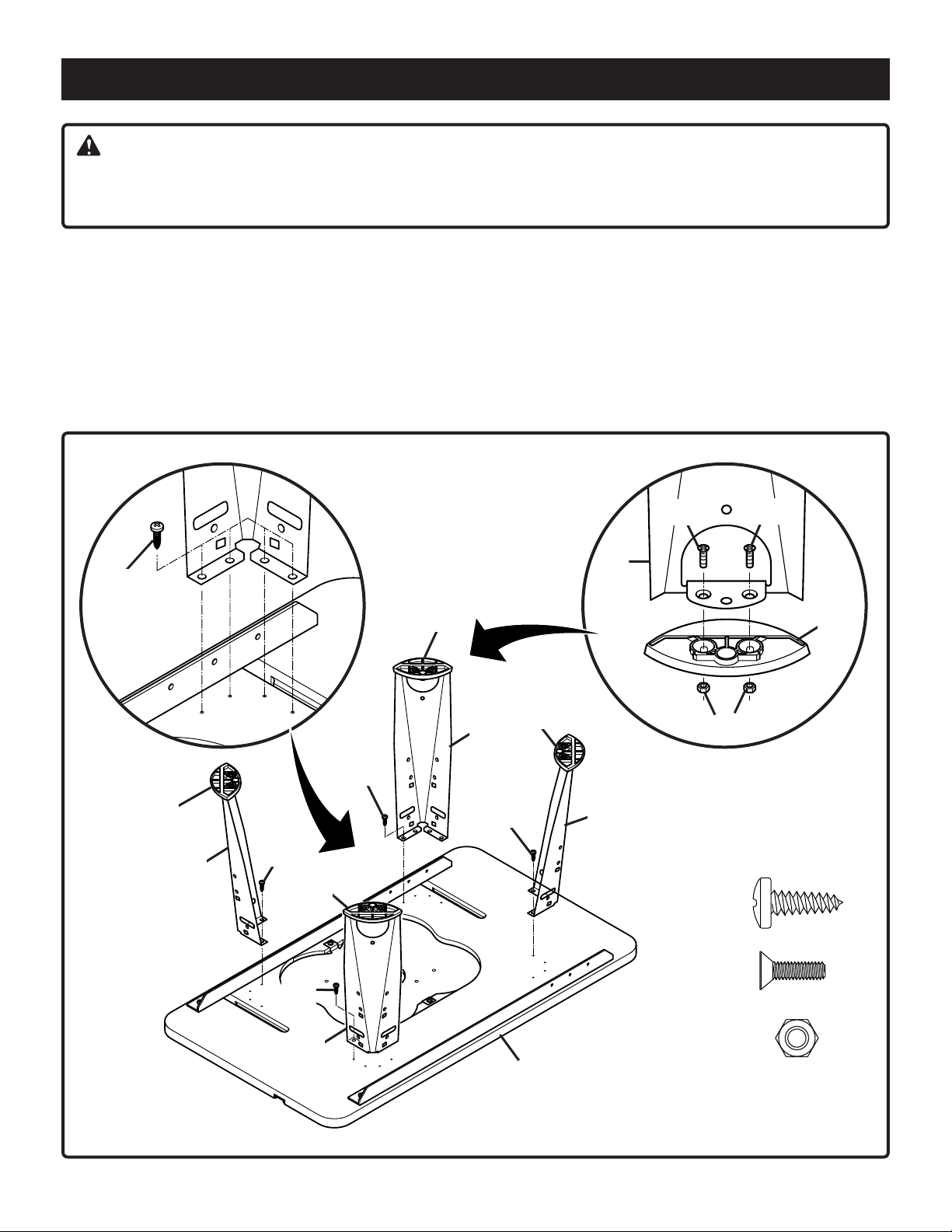
ASSEMBLING THE ROUTER TABLE
See Figure 2
1. Place router table top (C) upside-down on a flat surface.
Take care not to scratch the table top surface.
2. Place footpads (V) on the bottom of table legs (D) and
fasten together using 8 countersink screws (AK) and 8
hex nuts (AL) provided. Use a #1 Phillips screwdriver to
keep from stripping the screw heads.
3. Attach legs (D) securely to table top with 16 pan head
screws (AB). Use a #3 Phillips screwdriver to keep from
stripping the screw heads.
AB
AK
D
V
AB
V
D
D
AB
V
AB
D
V
AK
V
AL
AB (16)
AB
AK (8)
D
C
10
AL (8)
Fig. 2
Page 11
ASSEMBLY
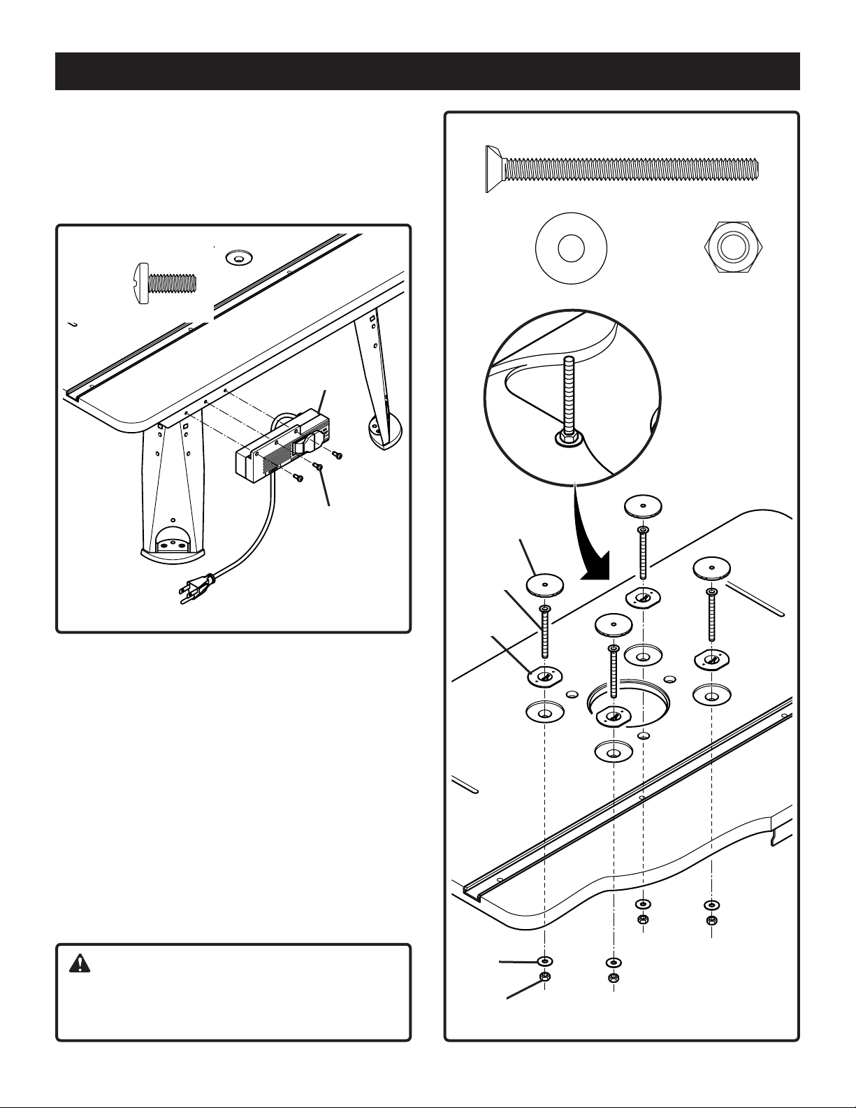
TO ATTACH THE SWITCH BOX
See Figure 3
4. Place the router table on its legs.
5. Use a #2 Phillips screwdriver to attach switch box (G) to
the switch box bracket with 3 self tapping screws (AF).
AF (3)
G
AC (4)
AD (4)AE (4)
AF
Fig. 3
To attach screws, washers and nuts for
mounting router
See Figure 4
6. Place the 4 flange nuts (U) in the 4 countersink holes of the
tabletop.
7. Insert the 4 countersink screws (AC) through holes in table
top. Tighten securely with the 4 hex nuts (AD) placing the
4 washer (AE) between the nuts (AD) and the tabletop.
Use an adjustable wrench or a combination wrench
(size 10 mm) to tighten the nuts (the detail in figure 4
shows the finished assembly).
8. Press the 4 caps (K) to cover the heads of the
countersink screws.
NOTE: Press the caps down until they are flush with table
top.
K
AC
U
CAUTION:
If you choose not to use the universal router mounting
system, simply remove the associated hardware (AD,
AE, U, AC), but keep the caps (K) in place.
AE
AD
Fig. 4
11
Page 12
ASSEMBLY
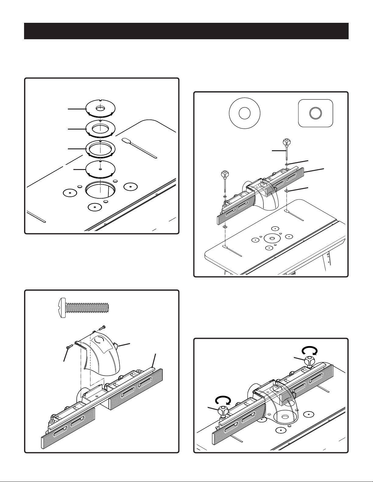
ASSEMBLE THE INSERTS
See Figure 5
9. Three of the inserts are for use with a specific size bit.
M
N
P
L
Fig. 5
See Figure 7
11. Place the 2 washers (AE) on top of the 2 holes in the
fence, insert the 2 knob screws (T) into the holes and
fasten on the other side with the 2 flat nuts (Z).
NOTE: Do not tighten the 2 flat nuts at this stage.
AE (2) Z (2)
T
AE
B
Z
TO ATTACH THE FENCE
See Figure 6
10. Attach the safety shield (A) to the fence (B) with 2 pan
head screws (AH). Use a #3 Phillips screwdriver to
tighten the screws.
AH (2)
A
B
AH
Fig. 7
See Figure 8
12. Place the fence on the tabletop so that the 2 flat nuts
(Z) are placed into the 2 slots in the table. Slide the
fence forward (always parallel with the front of the
table). When the fence is in the desired location
tighten the knob screws (T) by turning clockwise.
T
T
Fig. 6
Fig. 8
12
Page 13
ASSEMBLY
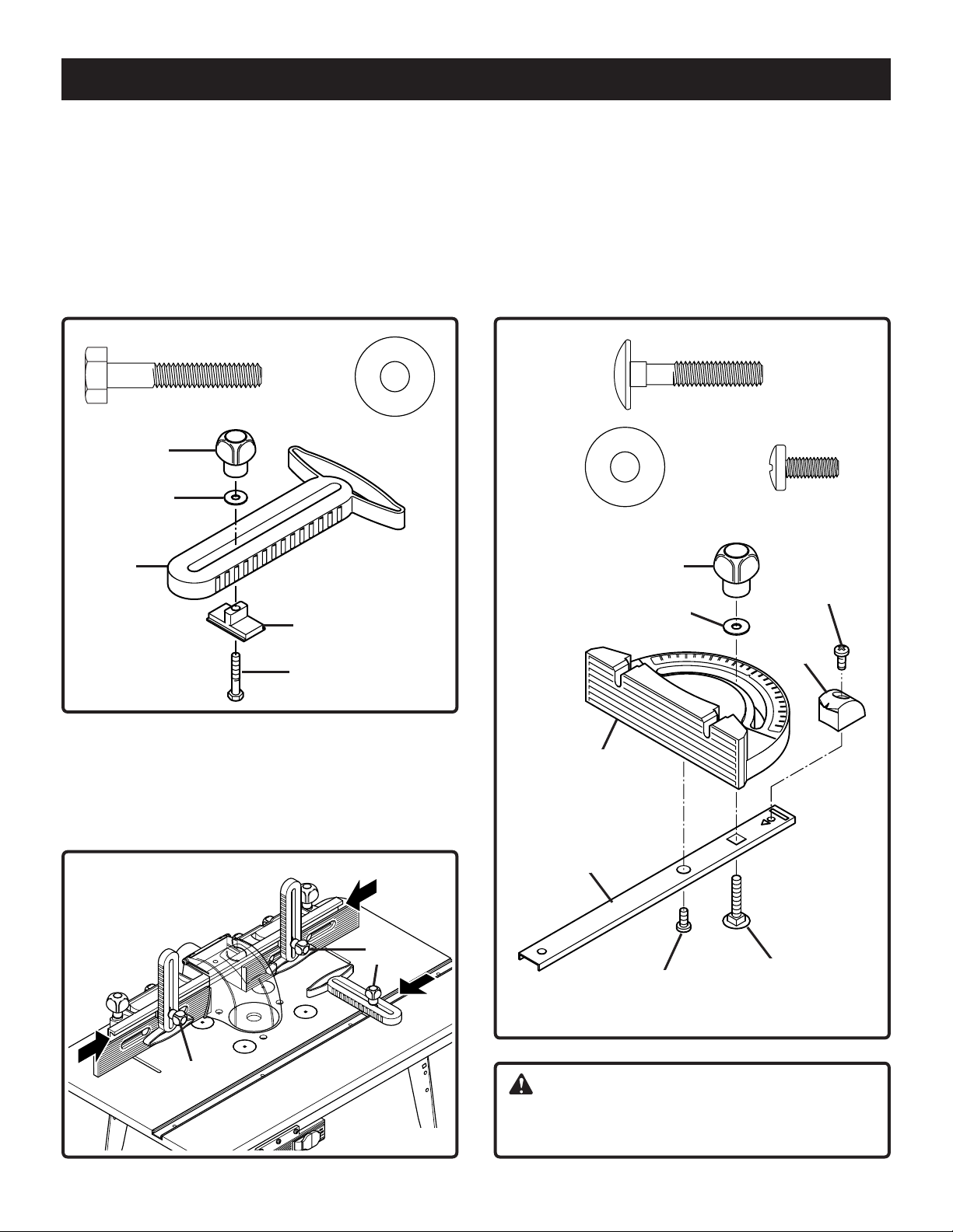
TO ATTACH THE FEATHERBOARDS
See Figure 9
13. Insert the hex head screw (AJ) into the sliding block
(J). Place the sliding block into the slot of the featherboard (H). Secure by placing washer (AE) over the hex
head screw (AJ). Screw together by turning the knob
(S) clockwise. NOTE: Do not completely tighten at this
stage. Repeat the above for the remaining 2 featherboards.
AJ (3)
AE (3)
S
AE
H
J
AJ
Fig. 9
ASSEMBLE THE MITER GUIDE
See Figure 11
15. Place the miter guide head (E) on top of the miter bar
(X). Now fasten together by screwing the self tapping
screw (AF) into the miter guide head. Assemble miter
guide by threading carriage bolt (AA) through miter bar
(X). Place washer (AE) and knob (S) on end of carriage
bolt. Tighten knob and then attach miter pointer (W) to
rear of miter bar (X) with self tapping screw (AF).
AA (1)
AE (1) AF (2)
S
AF
AE
W
See Figure 10
14. Position 2 of the featherboards on the fence and
secure by turning the knobs (S) clockwise. Place the
third featherboard into the slot provided on the tabletop and tighten in the same way.
S
S
Fig. 10
E
X
AF
AA
WARNING:
Before mounting the router make sure you have read
and understood pages 10-13 of your owner’s manual.
13
Fig. 11
Page 14
MOUNTING THE ROUTER
WARNING:
Always unplug router and remove router bits before
mounting to router table. Remove the fence, the
insert, the featherboards and the miter guide from the
tabletop before mounting the router.
There are three methods for attaching routers to router
table. The table will accept routers with bases up to 7" in
diameter. See chart below to see whether your router will
mount directly to the table or will require the use of the
adapter plate provided. It is also possible to attach the
router to router table with the universal clamping system.
NOTE: If your router is not one of those listed in the chart,
place the adapter base plate on top of the router base
plate and rotate until the holes in the two plates are
aligned. When hole patterns line up, the mounting scheme
has been identified.
Brand Model #
R160K, R160V
Ryobi
®
Porter Cable
Milwaukee
Hitachi
®
R161K, R161KT
R162K, R165
R180, R180PL
®
893PK, 895PK
®
R1801M
690, 691
693LRPK
694VK, 892
1001, 8931
9690LR
26941
5615-21
5616-21
5619-20
KM12VC
Adapter
hole pattern
A/AB
D
D
D
NOTE: If your router does not fit adapter base plate or if
you wish to mount router directly to the table for greater
cutting depth, remove the base plate from your router and
attach the router with the universal clamping system.
WARNING:
Do not remove the metal reinforcement plate mounted
to under side of the table top. The reinforcement plate
is necessary for the proper function of this router table.
I. Mounting Routers with 7"
Round Adapter Base Plate
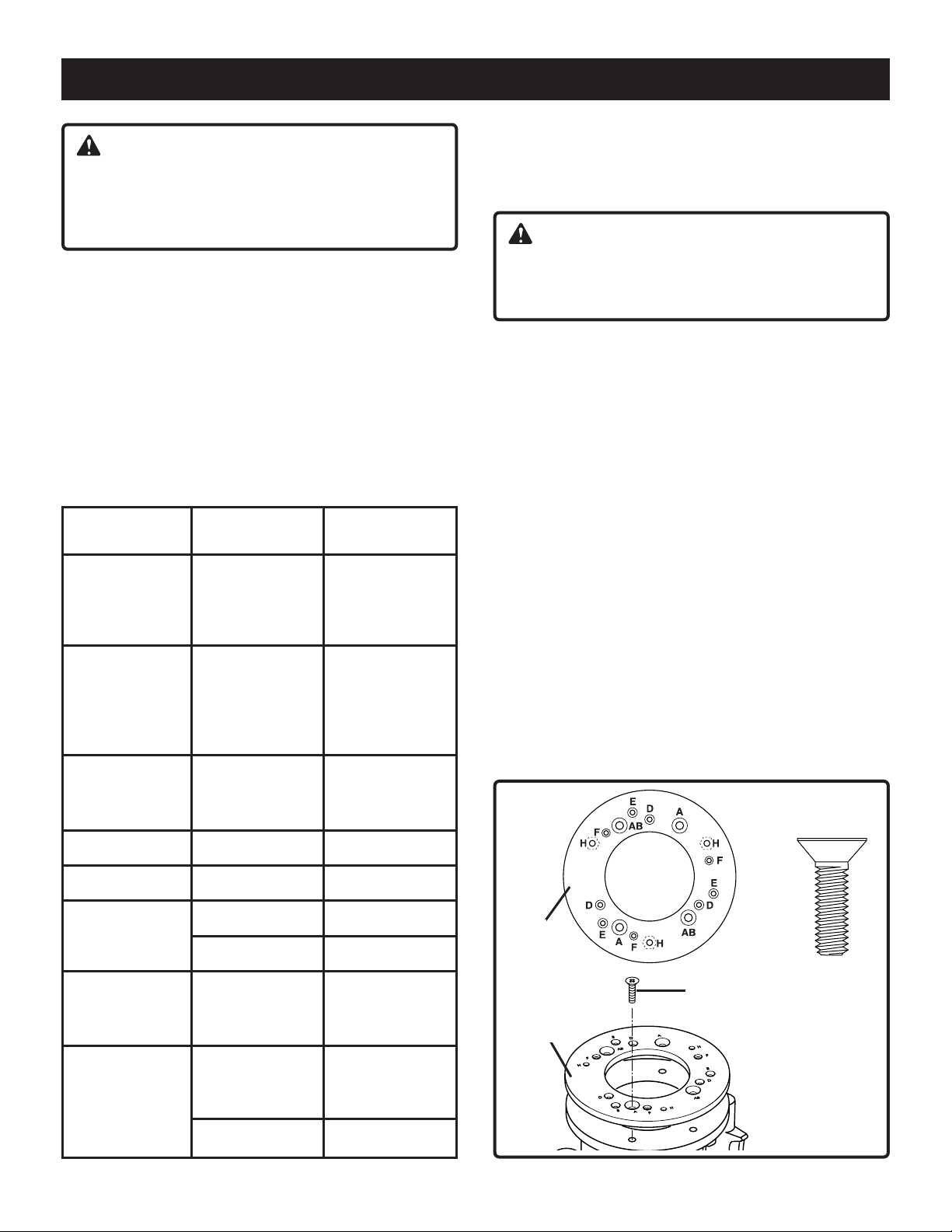
See Figure 12 and 13
1. Remove the base plate from router.
2. Place the adapter base plate (F) on the router base
according to mounting pattern identified in chart. See
Figures 12.
3. Use the screws removed from the router base plate to
attach the adapter base plate to the router base.
Tighten screws securely.
4. Routers with A and AB hole pattern use three countersink 5/16" - 18 X 3/4" screws (AM), to attach the
adapter base plate (F) to the router. For Ryobi routers
RE600 and RE601 use three M 8 x 20 countersink
screws (AN).
5. To mount Craftsman routers that use the
E-hole pattern to the adapter plate (F), three
10 - 32 x 1/2" countersink screws are required (not provided).
NOTE: Adapter base plate must be mounted to the router
using countersunk flat head screws.
AM/AN (3)
Black & Decker
Skil
®
®
DeWalt
Craftsman
®
7612
DW 610
F
F
F
DW 616
1810, 1815
1820, 1823
1825, 1835
1845-02
17504, 17505
17506, 17511
®
17515, 17528
17533, 26834
27500, 27510
27511
D
E
E
A
AM or AN
NOTE: Countersink
screws
F
Fig. 12
14
Page 15
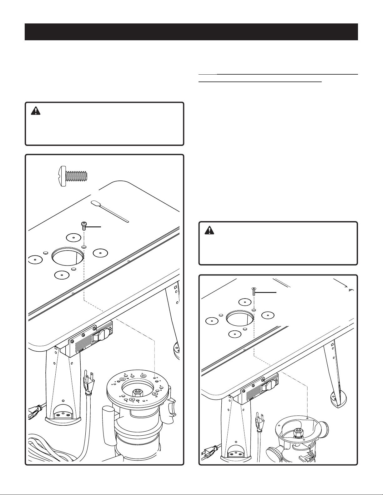
MOUNTING THE ROUTER
See Figure 13
6. Mount the router with adaptor base plate by putting the
pan head screws (AG) through the holes in the tabletop
and fasten to the nuts in the adapter plate (F) at position H. (The adapter plate comes from the factory with
the mounting nuts pressed into it.) Tighten securely.
CAUTION:
Make sure the screws from router base plate are
long enough to mount router securely. Replace if
necessary.
AG (3)
AG
II. Mounting Routers with Three-Hole
Base Plate (Hole Pattern "E")
Note: Refer to Hole Pattern Chart on page 14 to deter-
mine the correct hole pattern for your router.
See Figure 14
1. Remove router base plate from router by removing
screws.
2. While holding router upside down, position it to the
underside within the center ring of the table top.
3. Rotate router until the three mounting holes in router
base line up with the three larger holes in the table top.
4. Insert three machine screws from router base plate
through holes in tabletop and into router mounting
holes. Tighten securely.
5. To mount Craftsman routers that use the E-hole
pattern to the table top, use three 10 - 32 x 1/2" pan
head screws (not provided).
NOTE: For ease of use, position the router so the
ON-OFF switch is accessible from the front of the
table.
CAUTION:
Make sure the screws from router base plate are
long enough to mount router securely. Replace if
necessary.
Fig. 13
NOTE: Screw from
router base plate or
10-32 X 1/2" pan
head screw.
Fig. 14
15
Page 16
MOUNTING THE ROUTER
III. Mounting Routers with the universal
clamping system
Note: All routers will require using the adapter plate (F)
and locating pins (Y) when mounting the router to the
router table with the universal clamping system. Refer to
Hole Pattern Chart on page 14 to determine the correct
hole pattern for your router.
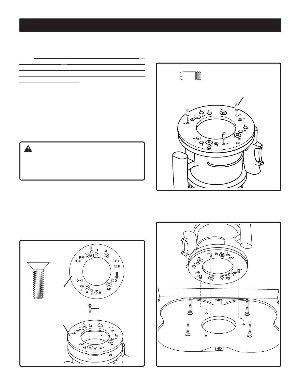
See Figure 15
1. Remove base plate from router.
2. Place the adapter base plate (F) on the router base
according to the mounting hole position chart on page
14.
3. Use screws removed from the router base plate to
attach the adapter base plate to the router base.
Tighten securely.
WARNING:
Make sure screws from router base plate match the
countersinks in the adapter plate and are long enough
to attach the base plate securely. Replace if necessary.
See Figure 16
6. Screw the three locating pins (Y) into nuts on adapter
plate from top side at hole position H.
Y (3)
Y
4. Routers with A and AB hole pattern use three countersink 5/16" - 18 X 3/4" screws (AM), to attach the
adapter plate (F) to the router. For Ryobi routers RE600
and RE601 use three M 8 x 20 countersink screws
(AN).
5. To mount Craftsman routers that use the E-hole pat-
tern to the adapter plate (F), three 10 - 32 x 1/2" countersink screws are required (not provided).
AM/AN (3)
F
AM or AN
NOTE: Countersink
screws
F
Fig. 16
See Figure17
7. Turn the router table upside-down. Align the three
locating pins in the bottom of the table top as shown.
Fig. 15
Fig. 17
16
Page 17
MOUNTING THE ROUTER
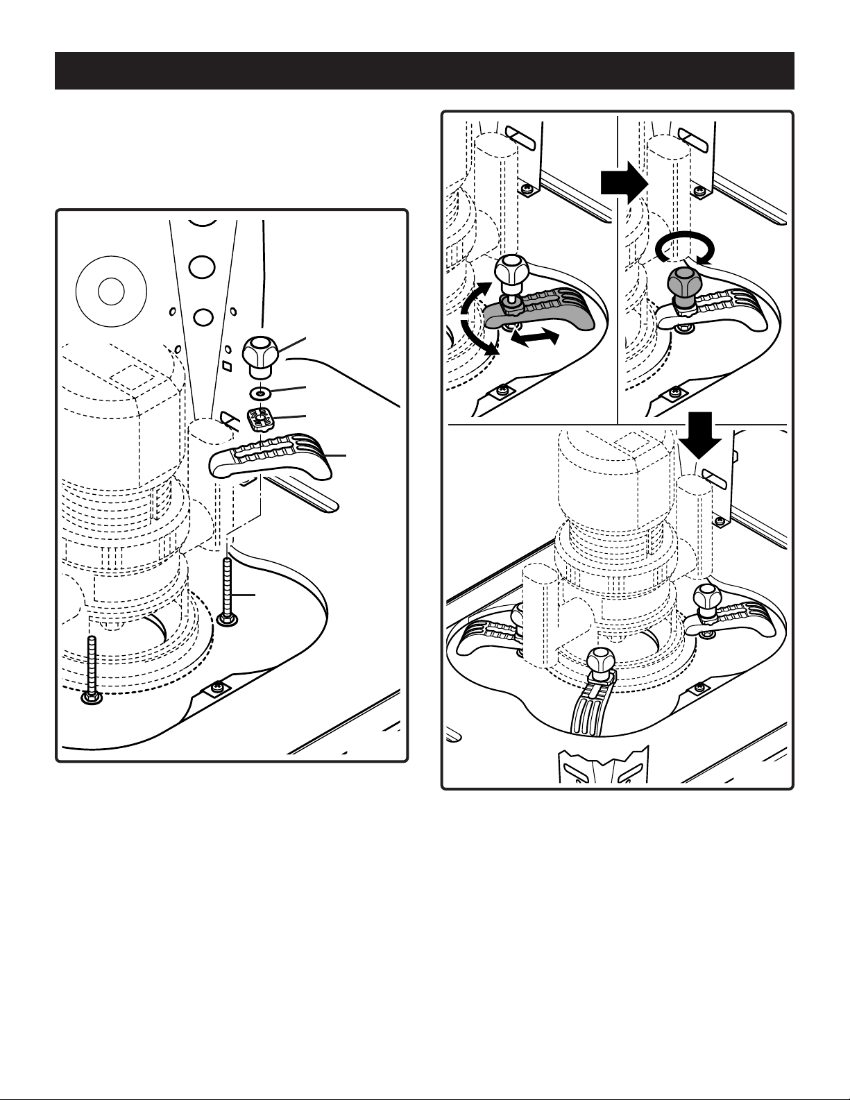
See Figure 18
8. Place clamp (R), swivel piece (Q), washer (AE), and
knob (S) on screw (AC) as shown. Leave assembly
loose to allow clamp to be adjusted. Repeat the above
procedures for the 3 remaining clamps.
AE (4)
S
AE
Q
R
AC
Fig. 18
See Figure 19
9. Position all 4 clamps on the adapter plate and tighten
securely with the 4 knobs.
10. Place the router table on its legs.
NOTE: Use a minimum of 3 clamps to secure the router
to the table.
NOTE: Routers larger than 2Hp should be mounted directly to the table top with mounting screws as described on
page 15.
NOTE: To remove the router when using the universal
clamping system, it may be necessary to disassemble one
or more of the clamps that secure the router to the table
top.
Fig. 19
17
Page 18
SWITCH BOX
PULL ON
PUSH OFF
RESET
OUTLETS
Introduction
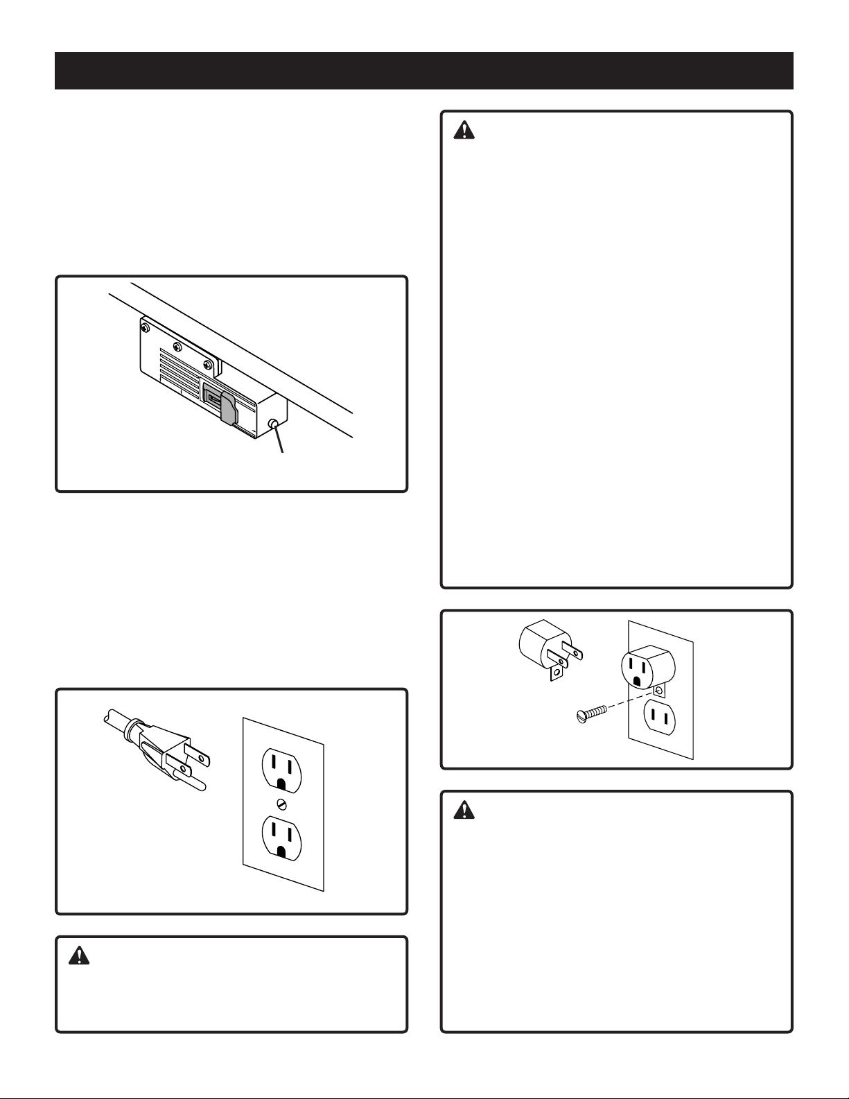
See Figure 20
A conveniently located Switch Box allows the operator to:
turn the router ON and OFF from the front of the table
simultaneously operate other devices such as a light or
a vacuum
It also features a resettable, internal circuit breaker that
protects your equipment against overloads.
reset button
Fig. 20
Electrical Hookup
See Figure 21
Proper grounding diverts potentially dangerous electricity
away from the operator. The switch box is intended for
use with a three-prong, grounded outlet. The switch
box's electrical cord features an equipment-grounding
connector and a grounding plug. Insert the plug into an
accommodating outlet that conforms to all local electrical
codes and the National Electric Code (NEC).
WARNING:
AVOID THE RISK OF ELECTRICAL SHOCK
NEVER connect the equipment grounding connector
(green wire) to a "hot" electrical terminal. When
repairing or replacing the electric plug or cord, DO
NOT connect the grounding connector to a "hot"
electrical terminal.
Consult a qualified electrician if you do not understand
the grounding procedures or if you are not sure
whether the switch box is correctly grounded.
REPLACE DAMAGED CORDS
Damaged and/or worn cords must be repaired or
replaced immediately.
Extension cords must be three-wire, 14 gauge or
larger (maximum 25 foot length), with three-prong
"male" plugs, and three hole "female" receptacles
fabricated to accept the tool's plug. The electrical
outlets on the bottom of the switch box accept
three-prong grounded plugs and the two-prong plugs
of double insulated tools.
If a correctly grounded outlet is unavailable, use a
temporary adapter to connect the switch box's threeprong plug to a two-hole receptacle. Make use of the
temporary adapter only until a qualified electrician
installs a correctly grounded, three-prong outlet. The
green rigid lug or grounding wire MUST connect to the
ground on the outlet. See Figure 22
Fig. 21
WARNING:
DO NOT MODIFY THE PLUG
If it does not fit correctly, a qualified electrician must
install a compatible outlet.
Fig. 22
WARNING:
RISK OF ELECTRIC SHOCK
DO NOT touch prongs when inserting or removing
plug from outlet. Improper grounding can produce
potentially hazardous electrical discharges that can, in
turn, cause serious injury or death - especially in wet
conditions, such as a basement, outside, or near
plumbing.
DO NOT attach a 3-way plug or any other adapter to
outlets on bottom of switch box.
Only use the switch box when it is properly assembled
to the router table AND when the router is properly
attached to the router table.
18
Page 19
SWITCH BOX
Switch Box Familiarization
The purpose of this section is to familiarize the user with
the operation of the switch box BEFORE the router is
plugged in.
WARNING:
DO NOT plug the router in at this time. An ON switch
will start and an unprepared user could possibly be
seriously injured.
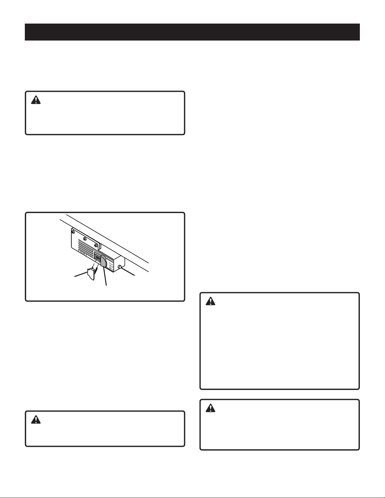
See Figure 23
The switch box also features a safety key that prevents
tools plugged into the switch box from being turned ON
inadvertently. Removal of the safety key disables the
switch box by locking the switch in the OFF position.
Strike the switch paddle with your hand to turn the router
OFF in an emergency situation. Please note paddle switch
positions and reset button at this time.
safety key
paddle switch
reset button
Fig. 23
Operation of Switch Box and Router
Make sure router switch is OFF and switch box is OFF
BEFORE proceeding.
1. Insert the yellow safety key into the switch box.
2. Position router power switch to ON.
NOTE: If your router requires the use of the switch trigger
and "Lock-On" button, refer to your Router Owner's
Manual for operating instructions.
3. Insert finger under paddle and pull switch to ON
position.
4. To turn router OFF, push paddle down.
WARNING:
Router bit must come to a complete stop before
leaving router table unattended.
For Routers With "LOCK-ON" Feature
The "LOCK-ON" feature will not permit the router to be
turned ON by the switch box, but it can be turned OFF by
the switch box. Operate as follows:
1. Place the switch box to ON as previously described.
The router should NOT start even though the trigger
lock is in the "LOCK-ON" position. Refer to your Router
Owner's Manual.
2. To start router, depress trigger and engage "LOCK-ON"
button. Router should start.
NOTE: The router will not start if the router switch is
already in the "LOCK-ON" position. In this case, unlock
the trigger, depress the trigger to start the router, then
re-engage the "LOCK-ON" button.
3. To turn router OFF, push switch paddle down.
Circuit Breaker
If an overload occurs, the circuit breaker inside the
switch box trips and interrupts power to the router and any
accessories. If this happens:
1. Unplug the power cord.
2. Remove the workpiece from the router bit and table.
3. Find the cause of the overload and correct.
4. Push the reset button to reset it.
See Figure 23.
5. Plug in power cord.
6. Follow instructions under Operation of Switch Box and
Router to reset router.
WARNING:
When router table is not in use, always:
1. Place the switch box in OFF position and remove
the safety key.
2. Place router power switch in OFF position.
3. Unplug switch box from wall outlet.
4. Remove router bit.
5. Make sure router collet assembly is below router
table.
6. Remove and place safety key in a secure location.
Remember where you place the safety key.
WARNING:
If breaker trips, or the router stalls, or if the power fails
for any other reason, place the switch box in the OFF
position, remove the safety key, and unplug the switch
box from the wall outlet.
5. Lock switch to OFF position by removing key from
switch box.
19
Page 20
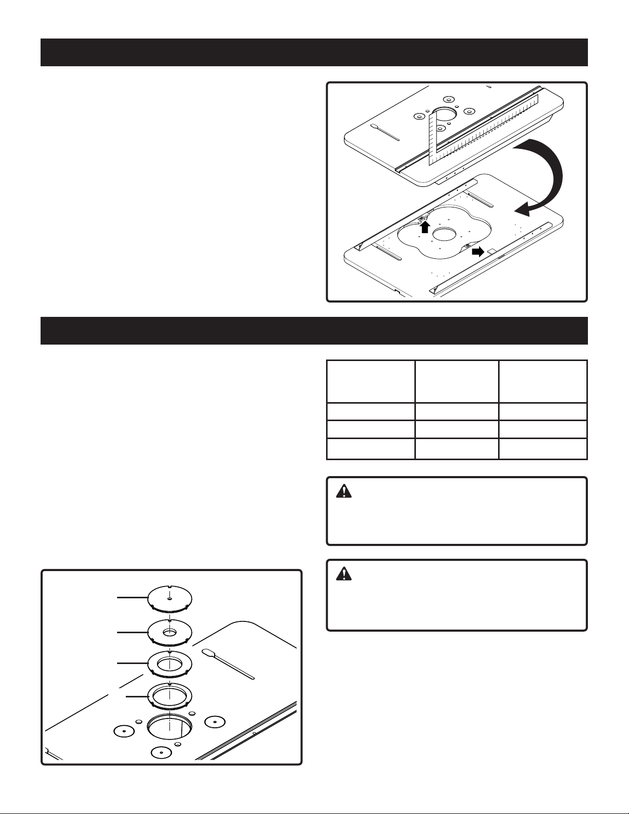
Table flatness adjustment
See Figure 24
Your router table comes equipped with 2 “L” brackets
mounted under it to help ensure the flatness of the
working surface. If the router table should ever become
warped, the flatness can be adjusted by shimming under
the “L” brackets. Loosen “L” brackets mounting screws
and place shims as necessary. Tighten the “L” bracket
screws securely. Check table top flatness with a
straightedge or the edge of a carpenters square.
OPERATION
Fig. 24
Connecting a Vacuum
A port is provided in the fence which will accept standard
1-1/4" and 2-1/2" vacuum hose connections. It works with
most shop vacuums. If the vacuum is plugged into the
switch box, it will turn ON and OFF simultaneously with
the router.
Assemble and using the Inserts
See Figure 25
Inserts help reduce the amount of wood chips and dust
that can accumulate on the router table. They can also
lend stability to the work piece.
Four inserts come with your router table. Three of the
inserts are for use with a specific size bit (refer to the
following chart).
L
M
N
P
Fig. 25
Diameter Diameter of Figure 25
of insert router bit Reference
to be used
1-1/8" 1" M
2-1/8" 2" N
2-7/8" 2-3/4" P
WARNING:
Do not use a router bit with a diameter greater than
3-1/2”. Consult your router manual for the maximum
size of router bit allowable.
WARNING:
Before removing insert, switch box must be in OFF
position, router switch must be in OFF position and
power cord must be unplugged from outlet.
Insert Use
1. Select correct insert for the router bit and your
application.
2. To assemble to router table, press the insert into the
hole in the table, applying pressure to all sides equally.
This assures that insert snaps into place.
3. Remove an insert by placing your finger into the hole in
the center. With light pressure, pull up on the insert.
NOTE: Remove the router bit from the router before
attempting to remove an insert.
20
Page 21
OPERATION
Using fence
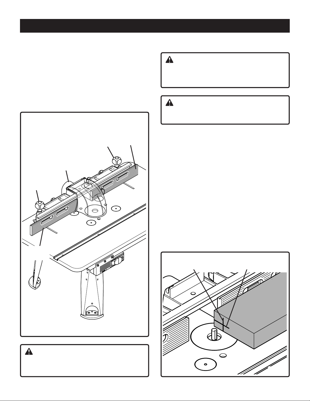
See Figure 26
To position the fence on tabletop, make this adjustment.
1. Place the fence on the tabletop.
2. Loosen the 2 knobs (T).
3. Slide the fence into the required position.
NOTE: Fence should always be parallel with the frontside
of the table.
4. Tighten the knobs (T) by turning clockwise.
Adustable
T
Fence
T
Adustable
fence
fence
Using your router/router table
WARNING:
Before you start work with your new router table: Refer
to your router owner's manual to see how the height of
the cut can be adjusted.
WARNING:
Make sure router is unplugged before starting
depth/height adjustments.
NOTE: Using scrap board that is smooth and true is
recommended for making this adjustment.
See Figure 27
1. At the end of the board, use a soft pencil to mark line
#1. This indicates the depth of the cut.
2. Then mark line #2, indicating the height of the cut.
3. Place your board so that it is snug against the fence
face. The end with lines #1 and #2 should be near the
bit.
4. Loosen fence clamping knobs enough so you can move
the fence easily. Move fence and board so that the
board contacts the outer edge of the router bit at line
#1.
5. Tighten fence clamping knobs.
6. Adjust router height so the cutting edge of the bit
contacts line #2.
7. Make sure bit is securely tightened in the collet.
Pencil line #1 Pencil line #2
CAUTION:
Make sure that the 4 knobs (connected to the
2 adjustable fences) are securely tightened.
Fig. 26
Fig. 27
21
Page 22
OPERATION
Using the router for beading
and edge cutting
See Figure 28
1. Loosen the knobs that hold the fences in place.
2. Position the fence for the desired cutting depth.
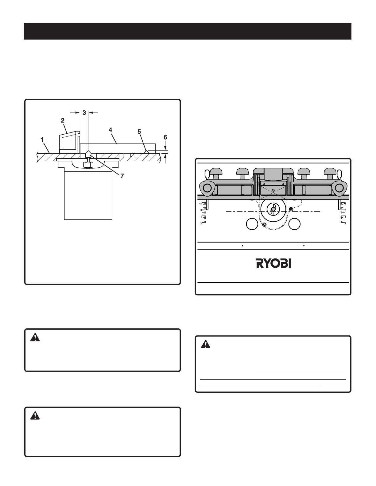
See Figure 29
The edge of the workpiece that slides along fence must be
straight and true for best results. (Use scrap to test
settings.)
1. With the router bit set at the required depth, place the
fence behind the bit at a distance determined by the
previous cut. Lower safety shield.
2. Secure both clamping knobs.
3. Slide the workpiece against the fence. Adjust fence for
subsequent cuts.
NOTE: For deep work, make progressively deeper cuts
until you reach the correct depth. To avoid overloading
router, remove waste material as you go.
1. Tabletop
2. Fence
3. Cutting depth
4. Workpiece
3. Tighten the knobs securing the fence in place.
4. Swing the safety shield over the router bit.
5. Your router/router table is now ready to use.
5. Successive cut
6. Depth of cut
7. Router bit
Fig. 28
WARNING:
Feed workpiece against the router bit's direction of
rotation. Unplug router prior to changing the bit,
modifying settings, or making any other adjustments.
Using ball-bearing-guided bits;
veining, fluting and grooving
WARNING:
To help reduce the chance of injury, make sure the
fence is as close as possible to the ball-bearingguided bit. Move the fence back ONLY enough to
permit the pilot to control the depth of cut.
Fig. 29
Routing without safety shield, and/or fence
Some jobs require that you rotate the safety shield out of
the way and remove the fence.
WARNING:
Using the router without the safety shield and fences
in place can lead to serious personal injury. Use
extreme caution: Operate the router without safety
shields and fences ONLY when absolutely necessary,
and with ballbearing-guided-type router bits.
Inside routing
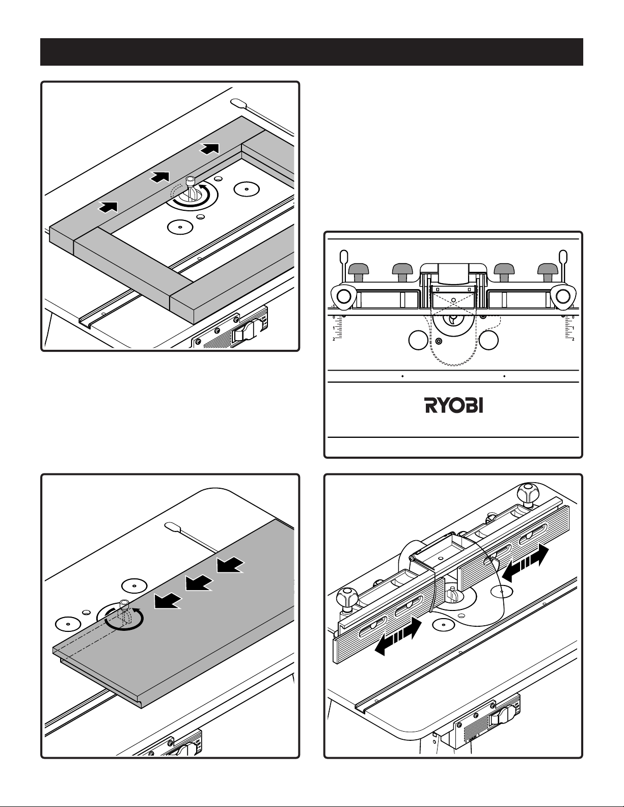
See Figure 30
1. Place your workpiece on the tabletop relative to the
router bit.
2. Feed your workpiece through the bit in the direction of
the arrow. Always feed against the router bit’s direction
of rotation.
22
Page 23
OPERATION
Using adjustable fences
See Figure 32 and 33
The fence slides can be positioned closer to the router bit
to provide better support of the workpiece.
To reposition the fence slides:
1. Loosen the 4 knobs (see Figure 32).
2. Reposition fence slides closer to the router bit. Leave a
3/16" gap (see Figure 33).
3. Tighten the 4 knobs securely (see Figure 32).
NOTE: DO NOT let the fence slides touch the router bit.
Fig. 30
Outside routing
See Figure 31
1. Place your workpiece on the tabletop relative to the
router bit.
2. Feed your workpiece through the bit in the direction of
the arrow. Always feed against the router bit’s direction
of rotation.
Fig. 32
Fig. 31
Fig. 33
23
Page 24
ACCESSORIES
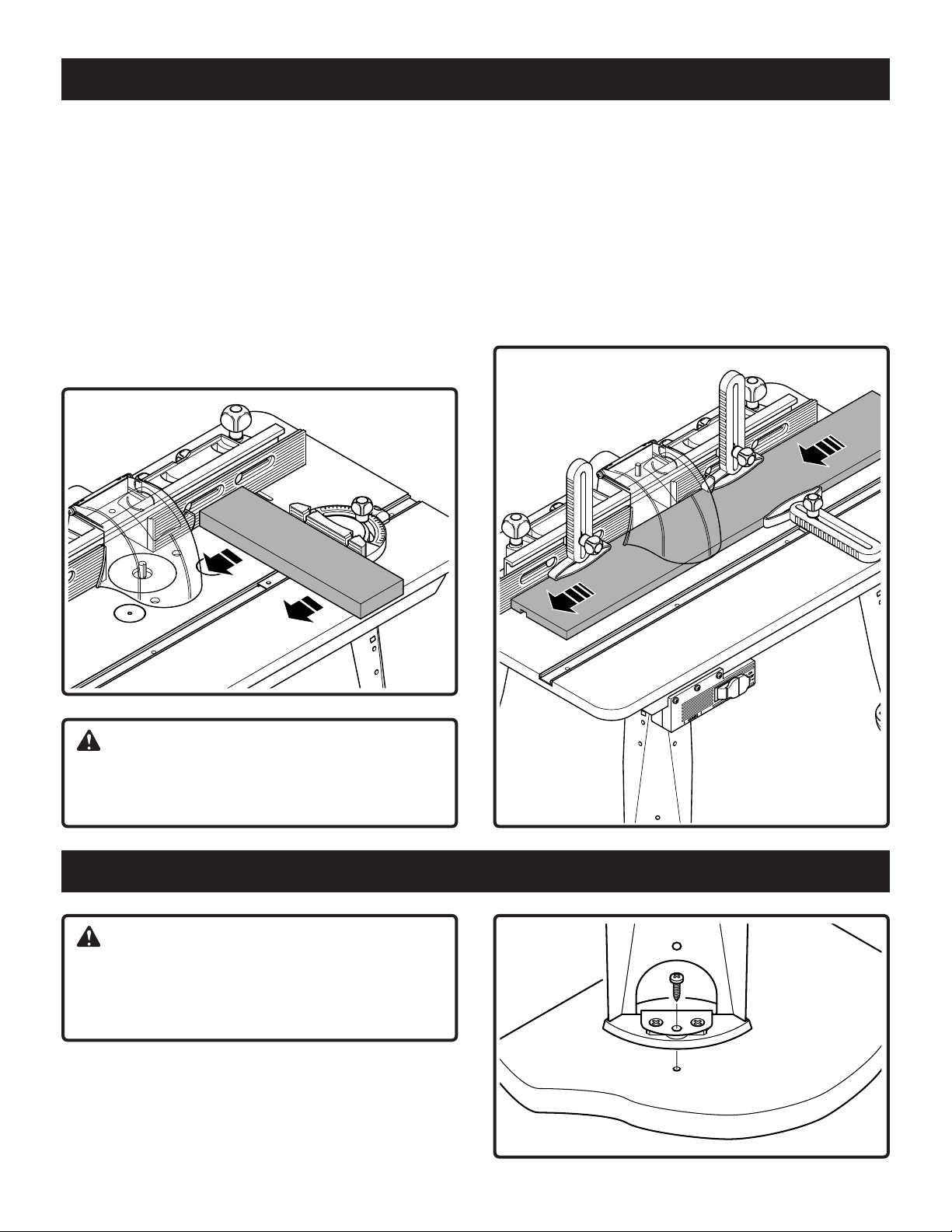
Using miter guide
See Figure 34
The miter guide can serve as extra support for routing
small workpieces and for ends of long workpieces.
NOTE: Make sure that the fence and miter bar slot are
parallel before cutting.
To cut miters, unclamp knob that secures the protractor
head. Turn head up to 60° in either direction. Retighten
knob.
When making cuts using the miter guide, hold the workpiece firmly against the fence, the miter guide, and the
table.
Using featherboards
See Figure 35
The featherboards provide support for the workpiece by
holding it securely, which helps minimize chatter and
kickback.
Insert the 2 featherboards as shown below, with the sliding blocks positioned in the slot of the fence and then
securely tighten the knobs.
Insert the third featherboard in the slot of miter chanel and
tighten knob.
Fig. 34
WARNING:
Do not allow any body part to be in line with the router
bit at any time when the miter gauge is in use. Doing
so could lead to serious personal injury.
SECURING THE ROUTER TABLE
WARNING:
DO NOT use the router table unless it is firmly
mounted to a stable work surface. Failure to securely
mount the router table could lead to serious personal
injury and/or property damage.
See Figure 36
1. Secure router table to the work surface using wood
screws or sheet metal screws and washers (not
provided) through the holes in the legs or use a one
hand bar clamp to clamp the leg to the work surface.
Fig. 35
Fig. 36
24
Page 25
REPAIR PARTS
29
13
24
5
9
27
26
15
14
25
3
25
8
10
24
8
24
27
19
37
36
34
11
7
13
30
6
20
21
17
33
18
35
24
32
13
12
30
41
28
31
24
16
6
30
6
30
30
6
44
46
30
1
30
23
24
2
23
22
45
4
13
27
24
24
43
13
39
44
42
24
40
13
40
24
2
38
39
40
40
25
Page 26

REPAIR PARTS
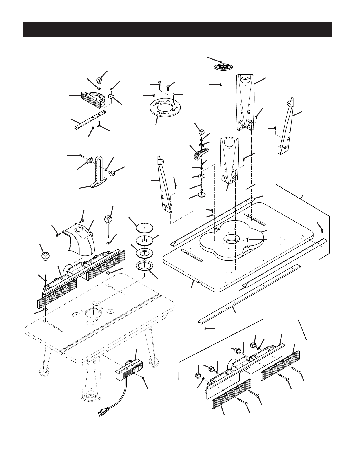
KEY NO. ITEM Part NO. DESCRIPTION QTY.
1C119800419 Tabletop 1
2B119900666 Fence 1
3A116600681 Safety shield 1
4G117920107 Switch box 1
5E116310035 Miter guide 1
6D117020052 Leg 4
7F119800217 Adapter plate 1
Hardware bag 1 119800219
8T119800225 Knob screw 2
9X117010029 Miter bar 1
10 AA 116700171 Carriage bolt (M6x30) 1
11 W116620424 Miter pointer 1
12 V 116600684 Footpad 4
13 S 119800224 Knob 8
Hardware bag 2 119800226
14 H 116610046 Featherboard 3
15 J 116410139 Sliding block 3
16 Q 116610042 Swivel piece 4
17 R 116420119 Clamp 4
18 K 116610685 Cap for tabletop 4
19 L 116600710 Insert 1 1
20 M 116600711 Insert 2, small hole 1
21 N 116610059 Insert 3, medium hole 1
22 P 116610060 Insert 4, large hole 1
Hardware bag 3 119900167
23 Z 117210158 Flat nut (M6) 2
24 AE 116700165 Washer (6,4 DIN 9021) 14
25 AH 116700177 Pan head screw (M6x25) 2
26 AJ 116700178 Hex head bolt (M6x35) 3
27 AF 116700163 Self tapping pan head screw (M5x12) 5
28 AK 116700179 Countersink screw (M4x12) 8
29 AL 116700180 Hex nut (M4) 8
30 AB 116700186 Pan head screw (5x16) 16
31 AD 116700167 Hex nut (M6) 4
32 U 117210157 Flange nut 4
33 AC 116700172 Countersink screw with nose (M6x65) 4
34 AG 116700190 Pan head screw (M6x12) 3
35 Y 116550017 Locating pin 3
36 AM 119900141 Countersink screw (5/16" - 18 x 3/4") 3
37 AN 119900212 Countersink screw (M8x20) 3
Repair parts fence (Key No. 2)
13 S 119800224 Knob 4
24 AE 116700165 Washer (6,4 DIN 9021) 4
38 116600677 Fence 1
39 116600678 Adjustable fence 2
40 116700166 Carriage bolt (M6x65) 4
Repair parts tabletop (Key No. 1)
30 AB 116700186 Pan head screw (M5x16) 8
41 116700175 Washer (6,4 DIN 125) 2
42 116410138 Miter chanel 1
43 116700187 Countersink screw (M4x12) 4
44 117020010 L-bracket 2
45 117920147 Tabletop 1
46 117010031 Reinforcement plate 1
26
Page 27

Notes
27
Page 28

OPERATOR’S MANUAL
ROUTER TABLE RT501W
• SERVICE
Now that you have purchased your tool, should a need ever exist for repair parts or
service, simply contact your nearest Ryobi Authorized Service Center. Be sure to
provide all pertinent facts when you call or visit. Please call 1-800-525-2579 for your
nearest Ryobi Authorized Service Center. You can also check our Web site at
www.ryobitools.com for a complete list of Authorized Service Centers.
• MODEL NO.
The model number of this product is found on the packaging and the manual.
• HOW TO ORDER REPAIR PARTS
WHEN ORDERING REPAIR PARTS,
ALWAYS GIVE THE FOLLOWING INFORMATION:
• MODEL NUMBER RT501W
RYOBI TECHNOLOGIES INC.
1428 Pearman Dairy Road Anderson, SC 29625
Post Office Box 1207 Anderson, SC 29622
www.ryobitools.com
Phone 1-800-525-2579
116 300 191
05 05
 Loading...