

Page 1

OPERATOR'S MANUAL
Random Orbit Sander
Model RS280
DOUBLE INSULATED
SPECIFICATIONS:
Sanding disc diameter 5 in. (127 mm)
Variable speed 0 - 13,000 opm
Diameter of orbit 5/32 in. (4 mm)
Rating 120 volts, 60 Hz, AC
2.8 Amperes
Net weight 3.5 lbs. (1.6 kg.)
THANK YOU FOR BUYING A RYOBI RANDOM ORBIT SANDER.
Your new Random Orbit Sander has been engineered and manufactured to Ryobi's high standard for dependability, ease of
operation, and operator safety. Properly cared for, it will give you years of rugged, trouble-free performance.
CAUTION: Carefully read through this entire operator's manual before using your new sander.
Pay close attention to the Rules for Safe Operation, Warnings, and Cautions. If you use your sander properly and only for what
it is intended, you will enjoy years of safe, reliable service.
Please fill out and return the Warranty Registration Card so we can be of future service to you.
Thank you again for buying Ryobi tools.
SAVE THIS MANUAL FOR FUTURE REFERENCE
Page 2

TABLE OF CONTENTS
■ Product Specifications .......................................................................................................................................1
■ Table Of Contents.............................................................................................................................................. 2
■ Rules For Safe Operation ...............................................................................................................................2-4
■ Unpacking and Features.................................................................................................................................5-7
■ Operation ......................................................................................................................................................7-10
■ Maintenance ....................................................................................................................................................11
■ Optional Accessories ....................................................................................................................................... 11
■ Exploded View and Parts List .....................................................................................................................12-13
■ Parts Ordering / Service .................................................................................................................................. 14
RULES FOR SAFE OPERATION
The purpose of safety symbols is to attract your attention to possible dangers. The safety symbols, and the
explanations with them, deserve your careful attention and understanding. The safety warnings do not by
themselves eliminate any danger. The instructions or warnings they give are not substitutes for proper accident
prevention measures.
SYMBOL MEANING
SAFETY ALERT SYMBOL:
Indicates danger, warning, or caution. May be used in conjunction with other symbols or pictographs.
DANGER: Failure to obey a safety warning will result in serious injury to yourself or to others. Always
follow the safety precautions to reduce the risk of fire, electric shock and personal injury.
WARNING: Failure to obey a safety warning can result in serious injury to yourself or to others. Always
follow the safety precautions to reduce the risk of fire, electric shock and personal injury.
CAUTION: Failure to obey a safety warning may result in property damage or personal injury to yourself
or to others. Always follow the safety precautions to reduce the risk of fire, electric shock and personal
injury.
NOTE: Advises you of information or instructions vital to the operation or maintenance of the equipment.
DOUBLE INSULATION
Double insulation is a concept in safety, in electric power
tools, which eliminates the need for the usual three-wire
grounded power cord. All exposed metal parts are isolated
from the internal metal motor components with protecting
insulation. Double insulated tools do not need to be grounded.
IMPORTANT
Servicing of a tool with double insulation requires extreme
care and knowledge of the system and should be performed
only by a qualified service technician. For service we suggest
you return the tool to your nearest RYOBI AUTHORIZED
SERVICE CENTER for repair. When servicing use only
identical Ryobi replacement parts.
WARNING:
The double insulated system is intended to protect the
user from shock resulting from a break in the tool's
internal wiring. Observe all normal safety precautions
related to avoiding electrical shock.
W ARNING:
Do not attempt to operate this tool until you have read
thoroughly and understand completely all instructions,
safety rules, etc. contained in this manual. Failure to
comply can result in accidents involving fire, electric
shock, or serious personal injury. Save operator's manual
and review frequently for continuing safe operation, and
instructing others who may use this tool.
Page 2
Page 3

RULES FOR SAFE OPERATION
READ ALL INSTRUCTIONS
■ KNOW YOUR POWER TOOL. Read operator's
manual carefully. Learn its applications and
limitations as well as the specific potential hazards
related to this tool.
■ GUARD AGAINST ELECTRICAL SHOCK by
preventing body contact with grounded surfaces.
For example: Pipes, radiators, ranges, refrigerator
enclosures.
■ KEEP GUARDS IN PLACE and in working order.
■ KEEP WORK AREA CLEAN. Cluttered areas and
benches invite accidents.
■ AVOID DANGEROUS ENVIRONMENT. Don't use
power tool in damp or wet locations or expose to
rain. Keep work area well lit.
■ KEEP CHILDREN AND VISITORS AWAY. All
visitors should wear safety glasses and be kept a
safe distance from work area. Do not let visitors
contact tool or extension cord.
■ STORE IDLE TOOLS. When not in use tools
should be stored in a dry and high or locked-up
place - out of the reach of children.
■ DON'T FORCE TOOL. It will do the job better and
safer at the rate for which it was designed.
■ USE RIGHT TOOL. Don't force small tool or
attachment to do the job of a heavy duty tool.
Don't use tool for purpose not intended - for
example - A circular saw should never be used for
cutting tree limbs or logs.
■ WEAR PROPER APPAREL. Do not wear loose
clothing or jewelry that can get caught in the tool's
moving parts and cause personal injury. Rubber
gloves and nonskid footwear are recommended
when working outdoors. Wear protective hair
covering to contain long hair and keep it from
being drawn into nearby air vents.
■ ALWAYS WEAR SAFETY GLASSES. Everyday
eyeglasses have only impact-resistant lenses; they
are NOT safety glasses.
■ PROTECT YOUR LUNGS. Wear a face or dust
mask if operation is dusty.
■ PROTECT YOUR HEARING. Wear hearing
protection during extended periods of operation.
■ DON'T ABUSE CORD. Never carry tool by cord
or yank it to disconnect from receptacle. Keep
cord from heat, oil and sharp edges.
■ SECURE WORK. Use clamps or a vise to hold
work. It's safer than using your hand and it frees
both hands to operate the tool.
■ DON'T OVERREACH. Keep proper footing and
balance at all times. Do not use while standing on
a ladder or unstable support.
■ MAINTAIN TOOLS WITH CARE. Keep tools sharp
at all times, and clean for best and safest
performance. Follow instructions for lubricating and
changing accessories.
■ DISCONNECT TOOLS. When not in use, before
servicing, or when changing or adjusting
attachments, blades, bits, cutters, sandpaper, etc.,
all tools should be disconnected from power supply.
■ REMOVE ADJUSTING KEYS AND WRENCHES.
Form habit of checking to see that keys and
adjusting wrenches are removed from tool before
turning it on.
■ AVOID ACCIDENTAL STARTING. Don't carry
plugged-in tools with finger on switch. Be sure
switch is off when plugging in.
■ MAKE SURE YOUR EXTENSION CORD IS IN
GOOD CONDITION. When using an extension
cord, be sure to use one heavy enough to carry
the current your product will draw. An undersized
cord will cause a drop in line voltage resulting in
loss of power and overheating. A wire gage size
(A.W.G.) of at least 16 is recommended for an
extension cord 100 feet or less in length. A cord
exceeding 100 feet is not recommended. If in doubt,
use the next heavier gage. The smaller the gage
number, the heavier the cord.
■ OUTDOOR USE EXTENSION CORDS. When
tool is used outdoors, use only extension cords
suitable for use outdoors. Outdoor approved
cords are marked with the suffix W-A, for example
- SJTW-A or SJOW-A.
■ NEVER USE THIS OR ANY POWER SANDER
FOR WET SANDING OR LIQUID POLISHING.
Failure to comply can result in electrical shock
causing serious injury or worse.
■ KEEP HANDS AWAY FROM SANDING AREA.
■ NEVER USE IN AN EXPLOSIVE ATMOSPHERE.
Normal sparking of the motor could ignite fumes.
Page 3
Page 4

RULES FOR SAFE OPERATION
■ INSPECT TOOL CORDS PERIODICALLY and if
damaged, have repaired at your nearest authorized
service center. Stay constantly aware of cord
location.
■ INSPECT EXTENSION CORDS PERIODICALLY
and replace if damaged.
■ KEEP HANDLES DRY, CLEAN, AND FREE
FROM OIL AND GREASE. Always use a clean
cloth when cleaning. Never use brake fluids,
gasoline, petroleum-based products or any strong
solvents to clean your tool.
■ STAY ALERT. Watch what you are doing and use
common sense. Do not operate tool when you are
tired. Do not rush.
■ CHECK DAMAGED PARTS. Before further use
of the tool, a guard or other part that is damaged
should be carefully checked to determine that it
will operate properly and perform its intended
function. Check for alignment of moving parts,
binding of moving parts, breakage of parts,
mounting, and any other conditions that may affect
its operation. A guard or other part that is damaged
should be properly repaired or replaced by an
authorized service center unless indicated
elsewhere in this instruction manual.
■ DO NOT USE TOOL IF SWITCH DOES NOT
TURN IT ON AND OFF. Have defective switches
replaced by an authorized service center.
■ INSPECT FOR and remove all nails from lumber
before sanding.
■ DRUGS, ALCOHOL, MEDICATION. Do not
operate tool while under the influence of drugs,
alcohol, or any medication.
■ WHEN SERVICING USE ONLY IDENTICAL
RYOBI REPLACEMENT PARTS.
■ MAKE THE WORKSHOP CHILD-PROOF with
padlocks, master switches, or by removing starter
keys.
■ POLARIZED PLUGS. To reduce the risk of electric
shock, this tool has a polarized plug (one blade is
wider than the other). This plug will fit in a polarized
outlet only one way. If the plug does not fit fully in the
outlet, reverse the plug. If it still does not fit, contact
a qualified electrician to install the proper outlet. Do
not change the plug in any way.
■ SAVE THESE INSTRUCTIONS. Review them
frequently and use them to instruct others who
may use this tool. If you loan someone this tool,
loan them these instructions also.
WARNING:
WEAR
YOUR
SAFETY
FORESIGHT IS BETTER
GLASSES
THAN NO SIGHT
The operation of any sander can result in foreign objects being thrown into your eyes,
which can result in severe eye damage. Before beginning power tool operation, always
wear safety goggles or safety glasses with side shields and a full face shield when
needed. We recommend Wide Vision Safety Mask for use over eyeglasses or standard
safety glasses with side shields.
Look for this symbol to point out important safety precautions.
It means attention!!! Your safety is involved.
SAVE THESE INSTRUCTIONS
Page 4
Page 5

UNPACKING
■ Carefully remove the sander, and accessories from box.
Make sure all items listed in the Packing List are included.
■ Do not discard the packing material until you have carefully
inspected and satisfactorily operated sander.
■ Examine all parts and accessories to make sure that no
breakage has occurred during shipping. Any damaged
part should be replaced before attempting to use the tool.
■ If any parts are damaged or missing, contact your nearest
Ryobi dealer to obtain replacement parts before attempting
to operate sander.
PACKING LIST
Sanding Disc
Conversion Pad (for velcro type sanding discs)
Warranty Card
Operator's Manual
Page 5
Page 6
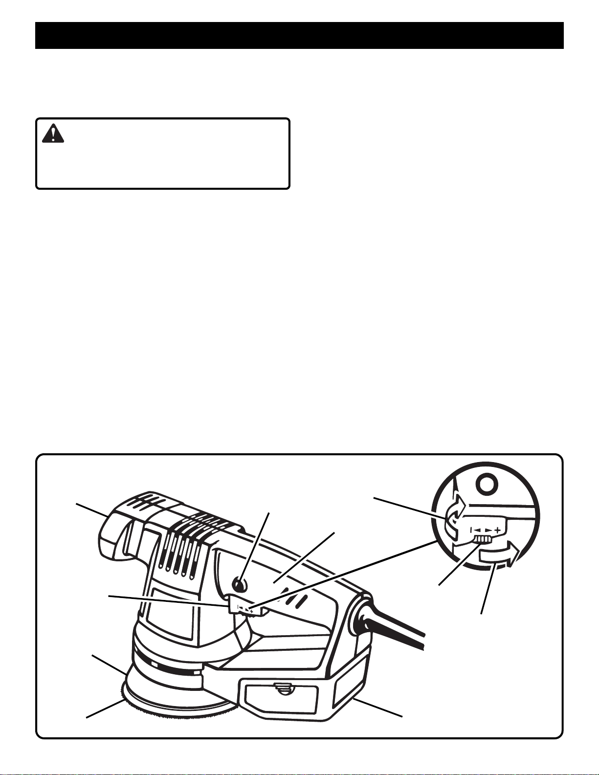
FEATURES
KNOW YOUR SANDER
See Figure 1.
Before attempting to use your sander, familiarize yourself
with all operating features and safety requirements.
WARNING:
If any parts are missing do not operate your sander until
the missing parts are replaced. Failure to do so could
result in possible serious injury.
Your sander is suitable for sanding with coarse, medium,
and fine grit sanding discs. It includes a dust box for dustless
sanding.
SWITCH
This tool is equipped with a simple switch control. To turn
your sander ON, depress the switch trigger.
Release the switch trigger to turn your sander OFF.
LOCK-ON-BUTTON
See figure 1.
Your sander is equipped with a "lock-on" feature, which is
convenient when continuous sanding for extended periods
of time is required. To lock-on, depress the switch trigger,
push in and hold the lock-on button located on the side of the
handle, then release switch trigger. Release lock-on button
and your sander will continue running. To release the lock,
depress switch trigger and release it.
If you have the "lock-on" feature engaged during use and
your sander becomes disconnected from power supply,
disengage the "lock-on" feature immediately.
See Figure 1.
VARIABLE SPEED
See figure 1.
Your sander has a variable speed control selector designed
to allow operator control and adjustment of speed. The
speed of your sander can be increased or decreased by
rotating the variable speed control selector in the direction of
the arrows shown in figure 1.
Note: Hold your sander in normal operating position and turn
the variable speed control selector counterclockwise to
increase speed. Turn clockwise to decrease speed.
If you desire to lock the switch on at a given speed, depress
the switch trigger, push in and hold the lock-on button, and
release the switch trigger. Next, adjust the variable speed
control selector until the desired speed is reached.
Note: If the variable speed control selector is fully
turned in the clockwise direction (zero setting) your
sander may not run.
Note: If you desire not to use the variable speed control
selector, turn it in the full counterclockwise direction.
This will allow the speed of your sander to be controlled
by the amount of switch trigger depression.
The following guidelines may be used in determining correct
speed for various applications.
Low speed is ideal when using tool as a buffer or polisher.
High speed should be used for sanding.
CONVERSION PAD
Converts the standard sanding pad from use with pressure
sensitive sanding discs for use with velcro type sanding discs.
FRONT
HANDLE
SWITCH
TRIGGER
BACKING
PAD
SANDING DISC
LOCK-ON
BUTTON
TO
DECREASE
SPEED
REAR HANDLE
VARIABLE
SPEED
CONTROL
SELECTOR
TO
INCREASE
SPEED
DUST BOX
Fig. 1
Page 6
Page 7
FEATURES
RANDOM ORBIT
The random orbit motion provides overlapping sanding
movements by combining orbital and turning motion. These
overlapping sanding movements provide fast cutting action
with excellent sanding results.
ELECTRICAL CONNECTION
Your sander has a precision built electric motor. It should be
connected to a power supply that is 120 volts, 60 Hz, AC
only (normal household current). Do not operate this tool
on direct current (DC). A substantial voltage drop will cause
a loss of power and the motor will overheat. If your tool does
not operate when plugged into an outlet, double-check the
power supply.
OPERATION
The backing pad on your sander provides the capability to
use sanding discs with pressure sensitive adhesive backing material. You also receive a conversion pad which allows use of sanding discs with velcro type backing material.
W ARNING:
Do not allow familiarity with your sander to make you
careless. Remember that a careless fraction of a second
is sufficient to inflict severe injury.
APPLICATIONS
(Use only for the purposes listed below)
■ Sanding on wood surfaces.
■ Removing rust from and sanding steel surfaces.
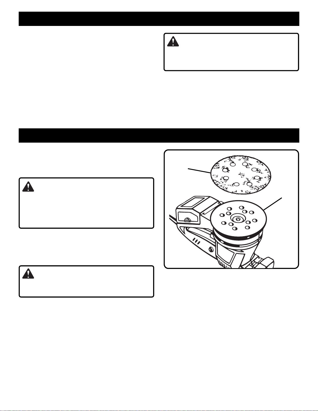
ADHESIVE
SANDING DISC
W ARNING:
Your sander should never be connected to power supply
when you are assembling parts, making adjustments,
assembling or replacing sanding disc, cleaning, or when not
in use. Disconnecting your sander will prevent accidental
starting that could cause serious personal injury.
TO ATTACH PRESSURE SENSITIVE ADHESIVE
SANDING DISC
See Figure 2.
■ Unplug your sander.
WARNING:
Failure to unplug your sander could result in accidental
starting causing possible serious personal injury.
■ Carefully peel paper backing from the pressure sensitive
adhesive type sanding disc.
■ Align holes in sanding disc with holes in backing pad,
then carefully press sticky side of disc against pad as
tight as possible.
Note: Holes in sanding disc must line up with holes in
the backing pad in order for the dustless feature of your
sander to function properly.
Note: It is recommended that you clean backing pad
occasionally by brushing lightly with a small brush. Dust
build-up on backing pad could cause sanding disc not to
stick properly.
BACKING
PAD
Fig. 2
SANDING DISC SELECTION
Selecting the correct size grit and type sanding disc is an
extremely important step in achieving a high quality sanded
finish. Aluminum oxide, silicon carbide, and other synthetic
abrasives are best for power sanding. Natural abrasives,
such as flint and garnet are too soft for economical use in
power sanding.
In general, coarse grit will remove the most material and finer
grit will produce the best finish in all sanding operations. The
condition of the surface to be sanded will determine which
grit will do the job. If the surface is rough, start with a coarse
grit and sand until the surface is uniform. Medium grit may
then be used to remove scratches left by the coarser grit and
finer grit used for finishing of the surface. Always continue
sanding with each grit until surface is uniform.
Page 7
Page 8
OPERATION
REMOVING SANDING DISC BEFORE STORAGE
Do not store your sander with the sanding disc installed.
Heat generated from sanding causes the pressure sensitive
adhesive to flow and form a tight bond between the backing
pad and sanding disc.
Removing the sanding disc soon after you have finished a
sanding operation avoids letting the adhesive set up. If the
sanding disc is left on the backing pad for an extended period
of time after use, the adhesive will set up and cause the
sanding disc to become difficult to remove.
It may also tear when removing. When this situation occurs,
it becomes difficult to clean the backing pad for the next
sanding disc.
Note: If you forget to remove the sanding disc after a sanding
operation, sand for a few minutes to soften the adhesive
backing before attempting to remove sanding disc.
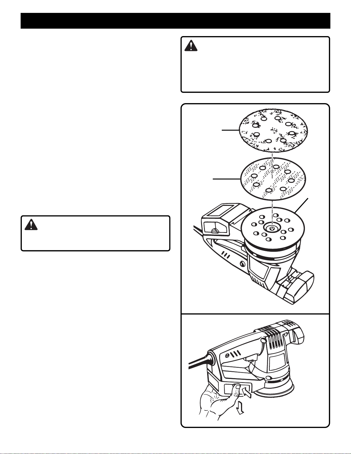
TO ATTACH CONVERSION PAD AND VELCRO
TYPE SANDING DISC
See Figure 3.
The conversion pad provided with your sander has a
pressure sensitive adhesive backing material. It is applied
by the same method as pressure sensitive adhesive paper.
■ Unplug your sander.
W ARNING:
To prevent the possibility of sanding dust or foreign
objects being thrown into your face or eyes, never attempt
to use your sander without the dust box properly installed.
Sanding dust or foreign objects being thrown into your
face could result in possible serious personal injury.
VELCRO TYPE
SANDING DISC
CONVERSION
PAD
BACKING
PAD
WARNING:
Failure to unplug your sander could result in accidental
starting causing possible serious personal injury.
■ Carefully peel paper backing from the conversion pad
and align with holes in backing pad. Firmly press sticky
side of conversion pad against backing pad. Your sander
is now ready to use velcro type sanding discs.
■ Align holes in velcro type sanding disc with holes in
conversion pad, then carefully press fuzzy side of sanding
disc against pad as tight as possible.
Note: Velcro type sanding discs can be reused for the
life of the sanding abrasive. It is recommended that you
keep the sanding disc backing and the conversion pad
clean to provide the best attachment. Clean occasionally
by brushing lightly with a small brush.
DUSTLESS SANDING
See Figures 4 and 5.
The dust box located on the rear of your sander provides a
dust collection system for your sander. Sanding dust is
drawn up through the holes of the sanding disc to collect in
the dust box during sanding operation.
Note: For more efficient operation, empty dust box when half
full. This will permit the air to flow through the box better.
Fig. 3
TABS
Page 8
TO REMOVE
Fig. 4
Page 9
OPERATION
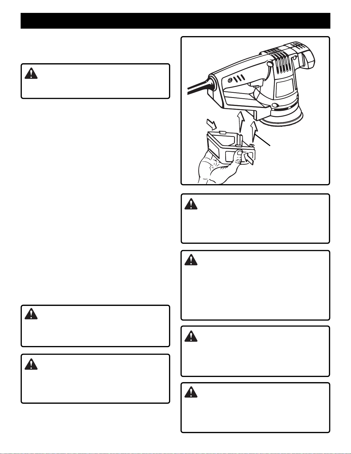
REMOVING DUST BOX
See Figure 4.
■ Unplug your sander.
WARNING:
Failure to unplug your sander could result in accidental
starting causing possible serious personal injury.
■ To release dust box, depress tabs located on each side of
dust box.
■ Slide dust box down and lift from sander as shown by the
arrows in figure 4.
■ Do not press on the filter material with your hand or
fingers. Filter material can be damaged.
Note: Filter material is located on sides of dust box.
■ Do not break tabs that secure dust box to sander.
■ Empty dust box.
TO INSTALL DUST BOX
See Figure 5.
■ Realign dust box with rear of sander.
■ Slide dust box on sander as shown in figure 5. You will feel
a soft click as the tab snaps into place.
Note: As mentioned above, be careful not to break the
tabs that secure dust box to sander.
EXTENSION CORDS
The use of any extension cord will cause some loss of power.
To keep the loss to a minimum and to prevent tool from
overheating, use an extension cord that is heavy enough to
carry the current the tool will draw.
A wire gage size (A.W.G.) of at least 16 is recommended for
an extension cord 100 feet or less in length. When working
outdoors, use an extension cord that is suitable for outdoor
use. The cord's jacket will be marked WA.
CAUTION:
TABS
TO INSTALL
DUST BOX
TABS
Fig. 5
W ARNING:
Do not use this product as a component of other products.
Also, do not use attachments or accessories not
recommended for use with this product. Any such use
could result in possible serious personal injury.
W ARNING:
To ensure proper brake operation after extended use,
periodically check its operation by removing the sanding
disc and running your sander without load (off the
workpiece). The backing pad should not take longer
than 6 seconds to stop. If it takes longer than 6 seconds
to stop, return the sander to your nearest RYOBI
AUTHORIZED SERVICE CENTER for repair.
Keep extension cords away from the sanding area and
position the cord so that it will not get caught on lumber,
tools, etc., during sanding.
WARNING:
Check extension cords before each use. If damaged
replace immediately. Never use tool with a damaged cord
since touching the damaged area could cause electrical
shock resulting in serious injury.
WARNING:
Do not wear loose clothing or jewelry when operating
sander. They could get caught in moving parts causing
serious injury. Keep head away from sander and sanding
area. Hair could be drawn into sander causing serious injury.
WARNING:
Before connecting your sander to power supply source,
always check to be sure the switch is not in ON position.
Failure to do so could result in accidental starting of your
sander resulting in possible serious injury.
Page 9
Page 10
OPERATION
PREPARING FOR OPERATION
CAUTION:
Be careful not to let your hand cover the air vents.
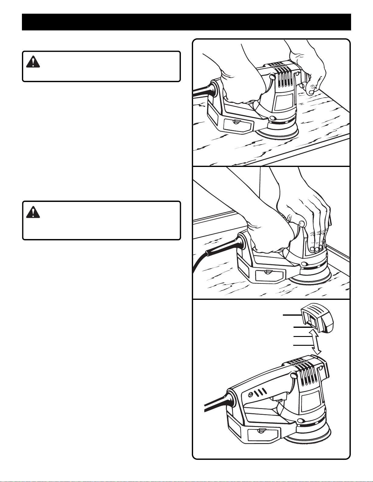
For ease of operation, your sander has both a front handle
and rear handle.
operation, which is necessary in order to maintain proper
control of your sander and keep both hands clear of the
sanding disc and sanding area. When operating your sander,
always use both hands.
Flush sanding can be performed with your sander when the
front handle is removed from sander.
Remove front handle by depressing tab under front handle
while pulling handle up and off of sander.
SANDING
See Figures 6 and 7.
Clamp or otherwise secure the work to prevent it from
moving under your sander.
See Figure 6.
See Figures 6 and 7.
This provides for two-hand
See Figure 7.
See Figure 8.
Fig. 6
WARNING:
Unsecured work could be thrown towards the operator
causing injury.
Place sander on workpiece so that all of sanding disc surface
is in contact with workpiece. Start your sander and move it
slowly over workpiece making successive passes in parallel
lines, circles, or crosswise movements. Upon completion of
sanding operation, turn sander off and wait until sanding disc
comes to a complete stop before removing from workpiece.
DO NOT FORCE. The weight of the unit supplies adequate
pressure, so let the sanding disc and sander do the work.
Applying additional pressure only slows the motor, rapidly
wears sanding disc and greatly reduces sander speed.
Excessive pressure will overload the motor causing possible
damage from motor overheating and can result in inferior
work. Any finish or resin on wood may soften from the
frictional heat. Do not allow sanding on one spot too long
as the sander's rapid action may remove too much material,
making the surface uneven.
Extended periods of sanding may tend to overheat the
motor. If this occurs, turn sander off and wait until sanding
disc comes to a complete stop, then remove it from
workpiece. Remove your hand from vent area, remove
sanding disc, then with your hand removed from vent area,
turn sander on and run it free without a load to cool motor.
As mentioned previously, flush sanding can be performed
with your sander. As shown in Figure 7, the front edge of
your sander allows flush sanding. Upon completion of
sanding operation, turn sander off and wait until sanding
disc comes to a complete stop before removing from
workpiece.
Fig. 7
FRONT HANDLE
TAB
TO REMOVE
TO INSTALL
Fig. 8
Page 10
Page 11
MAINTENANCE
WARNING:
When servicing use only identical Ryobi replacement parts. Use of any other parts may create a hazard or cause product
damage.
GENERAL
Avoid using solvents when cleaning plastic parts. Most
plastics are susceptible to damage from various types of
commercial solvents and may be damaged by their use. Use
clean cloths to remove dirt, carbon dust, etc.
WARNING:
Do not at any time let brake fluids, gasoline, petroleumbased products, penetrating oils, etc. come in contact
with plastic parts. They contain chemicals that can
damage, weaken, or destroy plastic.
LUBRICATION
All of the bearings in this tool are lubricated with a sufficient
amount of high grade lubricant for the life of the unit under
normal operating conditions. Therefore, no further lubrication
is required.
OPTIONAL ACCESSORIES
When electric tools are used on fiberglass boats, sports
cars, wallboard, spackling compounds, or plaster, it has
been found that they are subject to accelerated wear and
possible premature failure, as the fiberglass chips and
grindings are highly abrasive to bearings, brushes,
commutators, etc. Consequently, it is not recommended
that this tool be used for extended work on any fiberglass
material, wallboard, spackling compounds, or plaster. During
any use on these materials it is extremely important that
the tool is cleaned frequently by blowing with an air jet.
W ARNING:
Always wear safety goggles or safety glasses with side
shields during power tool operation or when blowing dust.
If operation is dusty, also wear a dust mask.
The following recommended accessories are current and were available at the time this manual was printed:
4600040 40 Grit Sanding Disc 5 Per Pack
4600060 60 Grit Sanding Disc 5 Per Pack
4600080 80 Grit Sanding Disc 5 Per Pack
4600100 100 Grit Sanding Disc 5 Per Pack
All individual sanding grits are available in handy five sheet packs.
4600150 150 Grit Sanding Disc 5 Per Pack
4600220 220 Grit Sanding Disc 5 Per Pack
4600320 320 Grit Sanding Disc 5 Per Pack
4600503 Conversion Pad 2 Per Pack
Page 11
Page 12
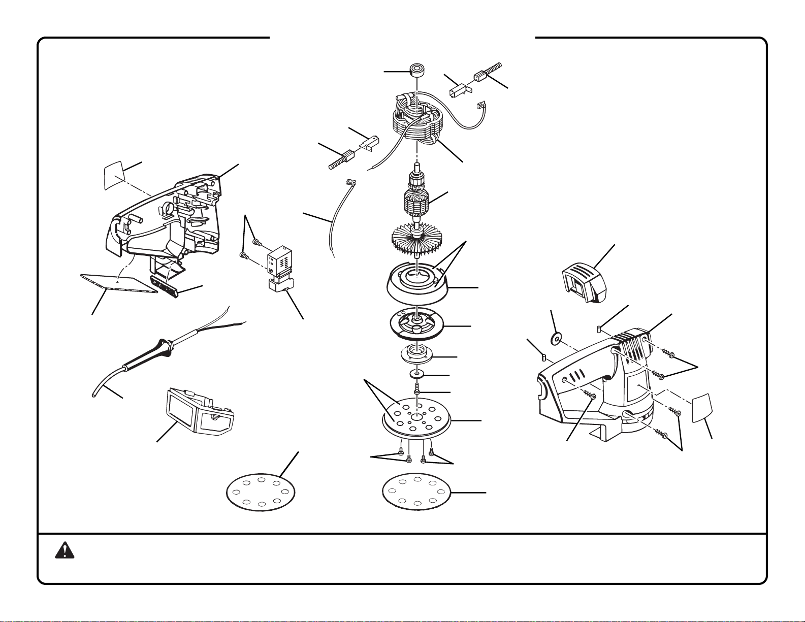
RYOBI SANDER – MODEL NUMBER RS280
Page 12
12
11
10
11
10
4
5
13
14
8
9
6
3
7
APPLY A THIN COAT OF
GREASE TO THIS
SURFACE
APPLY A THIN COAT
OF LOCTITE
ADHESIVE NO. 380
(BLACK MAX) TO
THIS SURFACE
15
16
24
17
18
23
22
24
5
25
19
2
20
1
28
21
21
25
26
25
27
WARNING: Improper repair of a double insulated tool can result in damages to the double insulation system possibly causing electrical shock or
electrocution. Any repairs requiring disassembly of your tool requires safety testing and should only be performed by a Ryobi Authorized Service Center.
For the repair center nearest you call 1-800-525-2579 in the United States or 1-800-265-6778 in Canada.
Page 13
RYOBI SANDER – MODEL NUMBER RS280
The model number will be found on a plate attached to the motor housing. Always mention the model number in all correspondence regarding your
SANDER or when ordering repair parts.
PARTS LIST
Page 13
Key Part
No. Number Description Quan.
1 969533-002 Dust Box ..............................................................1
2 990496-016 Cord .....................................................................1
3 970099-002 Seal......................................................................1
4 973712-001 Logo Plate ...........................................................1
5 970113-001 Housing Assembly...............................................1
6 969896-001 Small Gasket .......................................................1
7 968303-006 Switch ..................................................................1
8 968775-001 Screw (M3 x 7 Fil. Hd.)........................................2
9 969421-007 Lead.....................................................................1
10 968304-013 Brush Assembly...................................................2
11 999186-001 Brush Tube ..........................................................2
12 968305-009 Ball Bearing (NTN#608ZZ/1E) ............................1
13 968307-114 Field.....................................................................1
14 968306-119 Armature..............................................................1
15 973713-001 Skirt......................................................................1
Key Part
No. Number Description Quan.
16 973714-003 Counterbalance ...................................................1
17 968305-047 Bearing Cap w/Bearing .......................................1
18 703493-818 Washer ................................................................1
19 969649-001 Screw (#8-32 x 1/2 in. Pan Hd.) ..........................1
20 975241-002 Backing Pad ........................................................1
21 998586-001 Screw (#10-32 x 1/4 in. Pan Hd.) ........................4
22 969645-001 Front Handle........................................................1
23 623552-003 Stator Pad............................................................1
24 623019-004 Rubber Plug.........................................................2
25 968700-011 Screw (#6-19 x 3/4 in. Pan Hd.) ..........................5
26 981334-001 Data Plate............................................................1
27 973887-003 Sanding Disc .......................................................1
28 974484-001 Conversion Pad ...................................................1
972000-702 Operator’s Manual
* Standard Hardware Item — May Be Purchased Locally
Page 14
OPERATOR'S MANUAL
Random Orbit Sander
Model RS280
Double Insulated
EXTENSION CORD CAUTION
When using a power tool at a considerable distance from a power
source, be sure to use an extension cord that has the capacity to
handle the current the tool will draw. An undersized cord will
cause a drop in line voltage, resulting in overheating and loss of
power. Use the chart to determine the minimum wire size required in an extension cord. Only round jacketed cords should be
used.
When working with a tool outdoors, use an extension cord that is
designed for outside use. This is indicated by the letters "WA" on
the cord's jacket.
Before using any extension cord, inspect it for loose or exposed
wires and cut or worn insulation.
**Ampere rating
(on tool data plate) 0-2.0 2.1-3.4 3.5-5.0 5.1-7.0 7.1-12.0 12.1-16.0
Cord Length Wire Size (A.W.G.)
25' 16 16 16 16 14 14
50' 16 16 16 14 14 12
100' 16 16 14 12 10 —
CAUTION:
Keep the extension cord clear of the working area. Position the
cord so that it will not get caught on workpiece, tools, or other
obstructions while you are working with a power tool.
**Used on 12 gauge - 20 amp circuit.
• SERVICE
Now that you have purchased your tool, should a need ever exist for repair parts or
service, simply contact your nearest Ryobi Authorized Service Center. Be sure to
provide all pertinent facts when you call or visit. Please refer to the Service Center insert
or call 1-800-525-2579 in the United States or 1-800-265-6778 in Canada for your
nearest Ryobi Authorized Service Center. You can also check our web site at
www.ryobi.com for a complete list of Authorized Service Centers.
• MODEL NO. AND SERIAL NO.
The model number and serial number of this tool will be found on a plate attached to the
motor housing.
Please record the serial number in the space provided below.
• MODEL NUMBER
• SERIAL NUMBER
RYOBI AMERICA CORP.
1424 Pearman Dairy Road Anderson, SC 29625
Post Office Box 1207 Anderson, SC 29622-1207
Phone 1-800-525-2579
972000-702 Printed in U.S.A.
RS280
RYOBI CANADA INC.
Post Office Box 910
Cambridge, Ontario N1R 6K2
Phone 1-800-265-6778
 Loading...