

Page 1
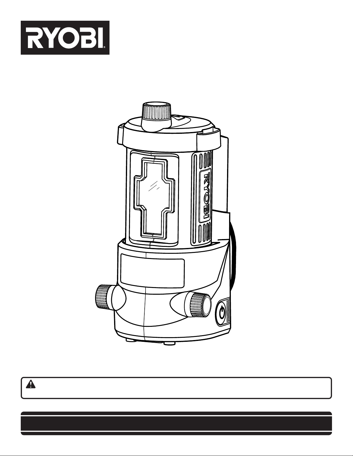
OPERATOR’S MANUAL
AIRgrip™ ProCross™ LASER LEVEL
SELF-LEVELING
ELL0006
Your laser level has been engineered and manufactured to our high standard for dependability, ease of operation, and
operator safety. When properly cared for, it will give you years of rugged, trouble-free performance.
WARNING: To reduce the risk of injury, the user must read and understand the operator’s manual before using
this product.
Thank you for your purchase.
SAVE THIS MANUAL FOR FUTURE REFERENCE
Page 2

TABLE OF CONTENTS
Introduction ..................................................................................................................................................................... 2
General Safety Rules ....................................................................................................................................................... 3
Symbols ........................................................................................................................................................................4-5
Features ........................................................................................................................................................................6-7
Assembly ......................................................................................................................................................................... 8
Operation .................................................................................................................................................................... 8-11
Maintenance .................................................................................................................................................................. 12
Troubleshooting ............................................................................................................................................................. 13
Parts Ordering / Service ...................................................................................................................................Back Page
INTRODUCTION
This product has many features for making its use more pleasant and enjoyable. Safety, performance, and dependability
have been given top priority in the design of this product making it easy to maintain and operate.
Please visit our website at
www.ryobitools.com to register this product.
Model No. ELL0006
2
Page 3
GENERAL SAFETY RULES
WARNING!
READ AND UNDERSTAND ALL INSTRUCTIONS. Fail-
ure to follow all instructions listed below, may result in
electric shock, fire and/or serious personal injury.
CAUTION:
Use of controls or adjustments or performance of procedures other than those specified herein may result in
hazardous radiation exposure.
CAUTION:
The use of an optical instrument with this product will
increase eye hazard.
The laser guide radiation used in the laser level attachment
is Class IIIa with < 5mW and 635 nm wavelengths. These
lasers do not normally present an optical hazard, although
staring at the beam may cause flash blindness.
Avoid direct eye exposure when using the laser and do
not project the laser beam directly into the eyes of others.
Serious eye injury could result.
Do not remove or deface any product labels. Removing
product labels increases the risk of exposure to laser
radiation.
Do not place the unit in a position that may cause anyone
to stare into the laser beam intentionally or unintentionally.
Serious eye injury could result.
Do not operate the laser level around children or allow
children to operate the product. Serious eye injury could
result.
Always turn the laser level off when not in use. Leaving the
product on increases the risk of someone inadvertently
staring into the laser beam.
Do not operate the unit in combustible areas such as in
the presence of flammable liquids, gasses, or dust.
Always ensure the laser beam is aimed at a surface with-
out reflective properties. Shiny reflective materials are not
suitable for laser use.
When using the base, always check to be sure the unit is
securely seated. Damage to the product and/or serious
injury to the user could result if the unit falls.
Handle the unit with care. Treat it as you would any other
optical device such as a camera or binoculars.
Avoid exposing the unit to shock, continuous vibration, or
extreme hot or cold temperatures. Damage to the product
and/or serious injury to the user could result.
Save these instructions. Refer to them frequently and
use them to instruct others who may use this product. If
you loan someone this unit, loan them these instructions
also.
3
Page 4
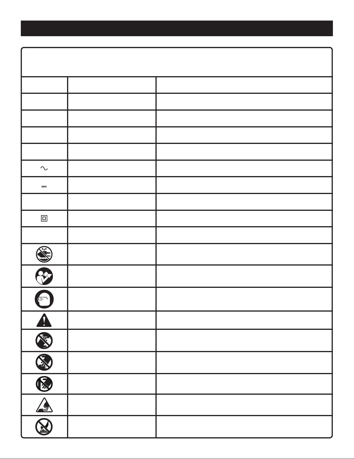
SYMBOLS
Some of the following symbols may be used on this product. Please study them and learn their meaning. Proper
interpretation of these symbols will allow you to operate the product better and safer.
SYMBOL NAME
V Volts Voltage
A Amperes Current
Hz Hertz Frequency (cycles per second)
W Watt Power
min Minutes Time
Alternating Current Type of current
Direct Current Type or a characteristic of current
n
o
.../min Per Minute Revolutions, strokes, surface speed, orbits etc., per minute
No Load Speed Rotational speed, at no load
Class II Construction Double-insulated construction
DESIGNATION/EXPLANATION
Wet Conditions Alert Do not expose to rain or use in damp locations.
Read The Operator’s Manual
Eye Protection
Safety Alert Precautions that involve your safety.
No Hands Symbol
No Hands Symbol
No Hands Symbol
No Hands Symbol
To reduce the risk of injury, user must read and understand
operator’s manual before using this product.
Always wear safety goggles or safety glasses with side shields and,
as necessary, a full face shield when operating this product.
Failure to keep your hands away from the blade will result in serious
personal injury.
Failure to keep your hands away from the blade will result in serious
personal injury.
Failure to keep your hands away from the blade will result in serious
personal injury.
Failure to keep your hands away from the blade will result in serious
personal injury.
Hot Surface
To reduce the risk of injury or damage, avoid contact with any hot
surface.
4
Page 5
SYMBOLS
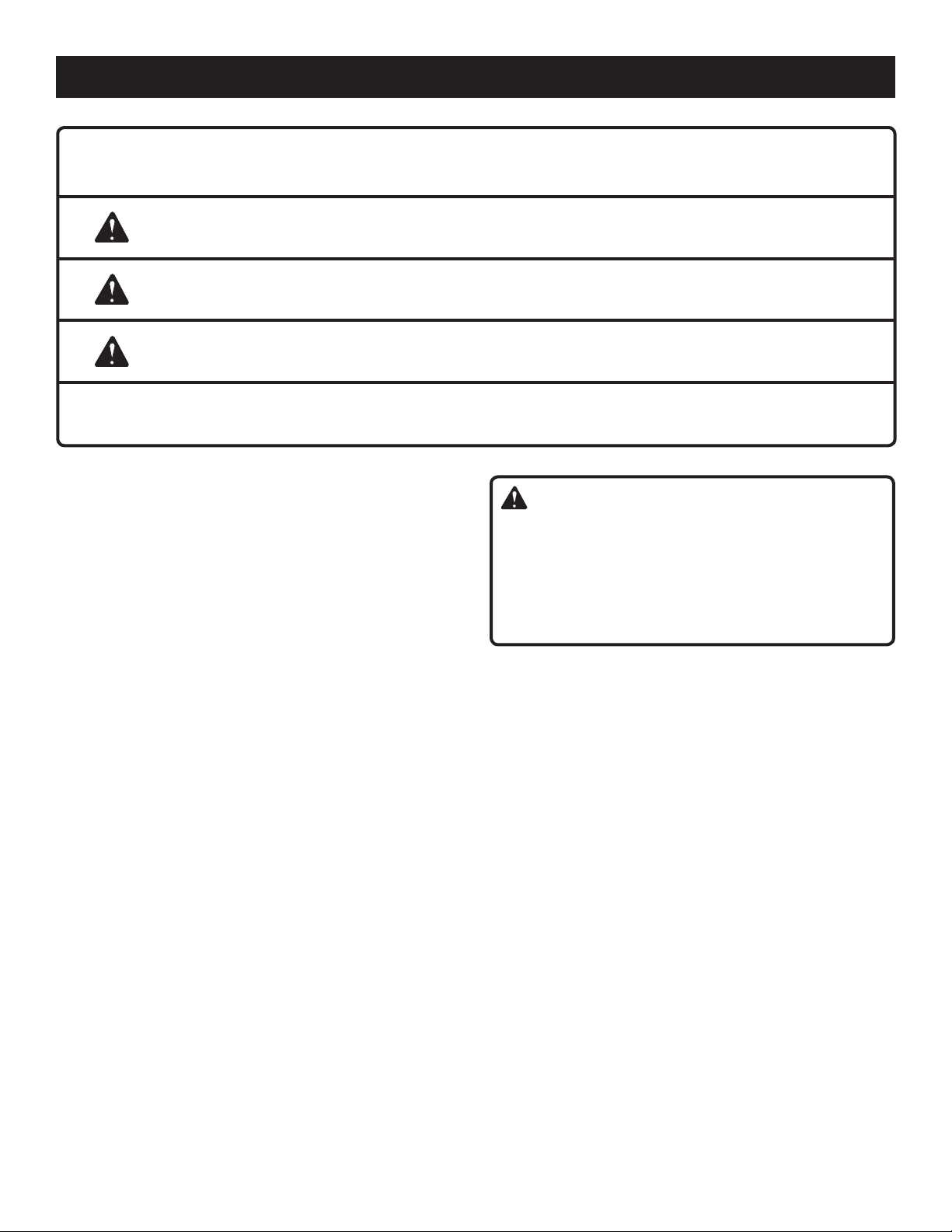
The following signal words and meanings are intended to explain the levels of risk associated with this product.
SYMBOL SIGNAL MEANING
DANGER:
WARNING:
CAUTION:
CAUTION:
Indicates an imminently hazardous situation, which, if not avoided, will result
in death or serious injury.
Indicates a potentially hazardous situation, which, if not avoided, could result
in death or serious injury.
Indicates a potentially hazardous situation, which, if not avoided, may result in
minor or moderate injury.
(Without Safety Alert Symbol) Indicates a situation that may result in property
damage.
SERVICE
This unit has no serviceable parts. If the unit fails due to
normal wear and tear within two years of purchase, return
with original receipt for a replacement unit at no charge. Call
1-800-525-2579 for your nearest AUTHORIZED SERVICE
CENTER.
WARNING:
To avoid serious personal injury, do not attempt to use this
product until you read thoroughly and understand completely the operator’s manual. If you do not understand
the warnings and instructions in the operator’s manual,
do not use this product. Call Ryobi customer service for
assistance.
SAVE THESE INSTRUCTIONS
5
Page 6

FEATURES
PRODUCT SPECIFICATIONS
Recommended Use.....................................................................................................................................................Indoors
AIRgrip Power Supply .......................................................................................................... 2 AA, 1.5 Volt Alkaline Batteries
Laser Power Supply ............................................................................................................. 2 AA, 1.5 Volt Alkaline Batteries
Battery Life for AIRgrip Vacuum ...................................................................................................... 4 Hours Continuous Use
Battery Life for Laser ..................................................................................................................... 40 Hours Continuous Use
Operating Temperature......................................................................................................................................32°F to 104°F
Laser ..............................................................................................................................................Class IIIa, < 5mW, 635 nm
Length of Laser Line ......................................................................................................................Up to 50 ft. each direction
Horizontal Accuracy ..................................................................................................................................... ± 1/4 in. at 25 ft.
Vertical Accuracy ...................± 1/4 in. at 25 ft. when measured at ± 4 ft. from center of crosshair laser on vertical surface
Laser Coverage ..................................................................................... 120° in Static Position, Rotating Head Covers 270°
ROTATIONAL
ADJUSTMENT KNOB
LASER
POWER/MODE
SELECTOR
LASER LENS
COVER
LASER LENS HOUSING
LINE HEIGHT
ADJUSTMENT
KNOB
AIRGRIP
VACUUM BASE
VACUUM BASE
ON/OFF BUTTON
VACUUM RELEASE
BUTTON
TRIPOD
MOUNTING HOLE
Fig. 1
6
Page 7

TRIPOD ADAPTOR
AND ADAPTOR
STORAGE
FEATURES
ROUGH SURFACE
ADAPTOR
PUSH PIN
AND PIN
STORAGE
PUSH PIN
HOLES
STRAP
LOOPS
MULTI-FUNCTION
BASE
KNOW YOUR CROSSHAIR LASER LEVEL
See Figures 1 - 2.
The safe use of this product requires an understanding of
the information on the product and in this operator’s manual
as well as a knowledge of the project you are attempting.
Before use of this product, familiarize yourself with all operating features and safety rules.
ADJUSTMENT KNOBS
The rotational and line height adjustment knobs are used to
fine tune your laser line settings.
AIRGRIP VACUUM TECHNOLOGY
This product uses a vacuum base that can adhere to smooth
surfaces. Using the vacuum seal prevents wall damage
caused by nails or adhesive tape. The vacuum base also
features a 5/8 in. - 20 tripod mount.
HOOK-AND-LOOP STRAP
The hook-and-loop strap can be used to attach the unit to
a variety of irregularly shaped surfaces.
HOOK-AND-LOOP
STRAP
Fig. 2
LASER POWER/MODE SELECTOR
The laser power/mode selector is used to select one of three
available operating modes — horizontal mode, vertical mode,
or crosshair mode.
MULTI-FUNCTION BASE
The multi-function base allows the laser level to be used on
irregularly shaped walls or objects. It features built-in loops
for a hook-and-loop strap, angled holes for push pins, and
storage compartments for the push pins and the 1/4 in.
tripod adaptor. The base also protects the unit when using
on a dusty or dirty surface and during storage.
ROUGH SURFACE ADAPTOR
The rough surface adaptor increases the number of surfaces
on which the AIRgrip vacuum can be used.
VACUUM BASE ON/OFF BUTTON
The vacuum base of your laser level conveniently turns on
and off at the touch of a button.
LASER HOUSING
The laser housing on your level rotates to allow for 360˚ of
laser line coverage.
7
Page 8

ASSEMBLY
UNPACKING
This product has been shipped completely assembled.
Carefully remove the product and any accessories from
the box. Make sure that all items listed in the packing list
are included.
Inspect the product carefully to make sure no breakage
or damage occurred during shipping.
Do not discard the packing material until you have care-
fully inspected and satisfactorily operated the product.
If any parts are damaged or missing, please call
1-800-525-2579 for assistance.
PACKING LIST
Crosshair Laser Level
AA Batteries (4)
Rough Surface Adaptor
Multi-Function Base
Push Pins (2)
Hook-and-Loop Strap
Tripod Adaptor
Case
Operator’s Manual
WARNING:
If any parts are damaged or missing do not operate
this product. Please return to the place of purchase or
call 1-800-525-2579 for assistance.
WARNING:
Do not attempt to modify this product or create accessories not recommended for use with this product. Any
such alteration or modification is misuse and could result
in a hazardous condition leading to possible serious
personal injury.
OPERATION
WARNING:
Do not allow familiarity with this product to make you
careless. Remember that a careless fraction of a second is
sufficient to inflict serious injury.
WARNING:
Do not use any attachments or accessories not recommended by the manufacturer of this product. The use of
attachments or accessories not recommended can result
in serious personal injury.
APPLICATIONS
You may use this product for the purposes listed below:
Aligning multiple pictures on a wall
Aligning wallpaper borders or chair rails
Lining up floor or wall tile
INSTALLING BATTERIES
See Figures 3 - 4.
There are two battery compartments for the laser level, one
for the AIRgrip vacuum and one for the laser.
To install batteries for the AIRgrip vacuum:
Locate the battery compartment on the base of the laser
level and remove the battery cover plate.
BATTERy COVER
PLATE
AA BATTERIES
Fig. 3
Install two AA batteries according to polarity indicators
(+ or −) inside the battery compartment.
Reinstall the battery cover plate.
To install batteries for the laser:
Rotate the line height adjustment knob to raise the laser
lens housing to its highest position.
8
Page 9

OPERATION
Rotate the laser lens housing until the battery compart-
ment comes into view.
Remove battery cover plate.
Install two AA batteries according to polarity indicators
(+ or −) inside the battery compartment.
Reinstall the battery cover plate.
NOTE: Remove the batteries from both the vacuum base
and the laser if you will not be using the unit for an extended
time.
TURNING THE VACUUM BASE ON/OFF
See Figure 5.
Press the button located on the right side of the vacuum
base to turn it on and off. Always wait for at least 5 seconds
between stopping and restarting the unit.
LASER LENS
HOUSING
BATTERy
COVER PLATE
ROTATIONAL
ADJUSTMENT
KNOB
LINE HEIGHT
ADJUSTMENT
KNOB
USING THE AIRGRIP VACUUM
See Figure 5.
Vacuum grip technology allows the unit to be attached to
most smooth surfaces.
NOTE: The multi-function base is not used when mounting
by vacuum grip.
Place the unit on the surface you want it secured to and
press against the surface slightly to seal.
Continue to hold the unit against the surface while press-
ing the on/off button.
Slowly release the unit when you hear a change in motor
sound.
NOTE: Before releasing the unit, make sure the unit is
securely adhered to the surface.
NOTE: To release the vacuum seal, turn the power to the
vacuum base off. For fast release, press the vacuum release
button located on the left side of the unit. Pulling the unit
off the wall without releasing the vacuum could damage
the product.
To reposition the laser level while it is adhered to a sur-
face, depress the vacuum release button while allowing
the AIRgrip vacuum to continue running. This will release
the seal enough to allow you to slide the unit to a different
position.
Fig. 4
AIRGRIP
VACUUM
ON/OFF
BUTTON
VACUUM
RELEASE
BUTTON
Fig. 5
LASER ON/OFF
BUTTON
TURNING THE LASER ON/OFF
See Figure 6.
Depressing the on/off button located on the top of the laser
level cycles the laser through three different operational
modes.
Depress the button once to turn on a horizontal laser
line.
Depress the button again to switch to a vertical line.
Depress the button a third time to switch to the crosshair
laser line.
Turn the laser off by depressing the button a fourth
time.
Fig. 6
9
Page 10

OPERATION
ROUGH SURFACE ADAPTOR
See Figure 7.
By using the rough surface adaptor, you can use the AIRgrip
feature to position the unit on many non-smooth surfaces,
including brick and painted cinder block.
NOTE: The AIRgrip feature cannot be used with stucco or
unpainted cinder block.
Place the adaptor over the AIRgrip base.
Place the unit against the desired surface and press
slightly to engage the seal.
Continue to hold the unit against the surface while press-
ing the on/off button.
Slowly release the unit when you hear a change in motor
sound.
CAUTION:
Before releasing the unit, make sure the unit is securely
adhered to the surface.
USING THE MULTI-FUNCTION BASE
See Figures 8 - 9.
Hook-and-loop strap and push pin methods are available
when the multi-function base is installed. To install, snap the
base over the AIRgrip vacuum seal.
HOOK-AND-LOOP STRAP: The strap can be used to attach
the laser level to irregularly shaped objects such as pipes,
boards, or metal grates.
Attach the strap to the multi-function base by threading it
through the loops. The looped (or fuzzy) side of the strap
should face the base.
Position the laser level against the surface where you
want it mounted.
Wrap the strap around the object being mounted (pipe,
board, etc.) and pass the end of the strap through the
retaining loop. Pull to tighten.
Place the hooked end of the strap against the looped (or
fuzzy) side of the strap and press together to secure.
NOTE: To use the hook-and-loop strap to hang the unit from
overhead, use the loops on top of the laser level housing.
PUSH PINS: Push pins allow the laser level to be mounted
to stucco and permeable surfaces.
Place the laser level on the surface where you want it
mounted.
Align push pin with angled hole located on one side of
laser level base and push in to secure.
In the angled hole on the other side of laser level base,
secure the second push pin.
Fig. 7
Fig. 8
10
Fig. 9
Page 11

OPERATION
USING A TRIPOD
See Figure 10.
The laser level has a 5/8 in.-20 threaded fitting for attaching
to a tripod base (not included). This method of mounting
is ideal for leveling kitchen cabinets, countertops, window
framing, and more.
If a 1/4 in. tripod fitting is needed, thread the adaptor inside
the 5/8 in. mounting hole and tighten with a flat blade screwdriver before attaching to tripod.
CAUTION:
Use caution when using laser level in base. Do not orient
in a way that will allow the laser level to slide or fall out
of the base.
OPERATING THE LASER LEVEL
See Figures 10 - 11.
WARNING:
The typical alkaline battery life for the AIRgrip vacuum
system is four hours. Replace with fresh alkaline batteries
prior to four hours of use. Failure to heed this warning
could result in damage to the product and/or serious
personal injury.
Before initial use, wipe AIRgrip vacuum base with a damp
cloth to remove any residue.
Place the level in the area where you want the laser lines
projected. Refer to Using the AIRgrip Vacuum or Using
the Multi-Function Base earlier in this manual if adhering
to a surface is desired.
Turn on the laser.
Rotate the laser housing to position the laser lines in the
general area desired. Then use the adjustment knobs to
fine-tune the line position.
NOTE: Due to construction inaccuracy, walls may not be
perfectly straight. This may cause the laser to have slight
variances when in the level position.
The laser level is self-leveling when used within the prod-
uct specifications listed earlier in this manual. If operating outside of the specifications listed, the laser line will
appear to have a textured pattern.
LASER LEVEL
MOUNTED
ON A TRIPOD
ROTATIONAL
ADJUSTMENT KNOB
LINE HEIGHT
ADJUSTMENT
KNOBS
Fig. 10
Fig. 11
WARNING:
Use of controls or adjustments or performance of procedures other than those specified herein may result in
hazardous radiation exposure.
11
Page 12

MODEL NO.
ELL0006
WAVE LENGTH: 630-670 NM
MAX. POWER OUTPUT < 5MW
CLASS IIIA LASER PRODUCT
LASER RA DIATIONAVOID DIRECT
EYE EXPO SURE
Complies with 21
CFR parts 1040.10
and 1040.11
Rayonnement laser
- éviter le contact oculaire
direct Lire les instructions
du manuel.
PELIGRO
Radiación láser
- Evite la exposición directa
de los ojos. Lea las
instrucciones en el manual.
EVITE La Radiación De
Laser de la EXPOSICIÓN
Emitida De Esta
Abertura
DANGER
ÉVITEZ Le Rayonnement
De Laser d'EXPOSITION
Émis De Cette
Ouverture
L
a
s
e
r
r
a
d
i
a
t
i
o
n
e
m
i
t
t
e
d
f
r
o
m
t
h
e
s
e
a
p
e
r
t
u
r
e
s
.
A
V
O
I
D
E
X
P
O
S
U
R
E
-
DANGER
MAINTENANCE
WARNING:
To avoid serious personal injury, always remove the batteries from the product when cleaning or performing any
maintenance.
GENERAL MAINTENANCE
Avoid using solvents when cleaning plastic parts. Most
plastics are susceptible to damage from various types of
commercial solvents and may be damaged by their use. Use
clean cloths to remove dirt, dust, oil, grease, etc.
WARNING:
Do not at any time let brake fluids, gasoline, petroleumbased products, penetrating oils, etc., come in contact
with plastic parts. Chemicals can damage, weaken or
destroy plastic which may result in serious personal
injury.
Store the unit indoors.
When not in use, the vacuum base and attachments
should be kept in the protective case.
Keep the unit free of dust and liquids. Use a damp cloth
and mild soap to clean the outside casing. Avoid using
solvents when cleaning plastic parts. Most plastics are
susceptible to damage from various types of commercial
solvents and may be damaged by their use.
To clean the laser lens, if needed, use ONLY a soft cloth
or cotton swab moistened with glass cleaner.
Check the batteries regularly to avoid deterioration.
Remove the batteries from both the vacuum base and
the laser if you will not be using the unit for an extended
time.
Do not disassemble the laser level. This could cause
exposure to hazardous laser radiation.
Do not attempt to change any part of the laser lens.
ALWAYS BE AWARE of the location where
the laser light is emitted when using the laser
level attachment. ALWAYS MAKE SURE that
any bystanders in the vicinity of use are made
aware of the dangers of looking directly into
the laser beam.
12
Page 13

TROUBLESHOOTING
Problem Possible Cause Solution
Vacuum not running. Batteries are low.
Power is turned off.
Laser line projection is weak. Batteries are low. Replace batteries.
Laser line is hard to see. Light in area is too bright.
Line is being projected beyond the
specifications listed earlier in this
manual.
Laser line is not working. Power is not on.
Batteries are low.
Laser line is dim. Batteries are low. Replace batteries.
Vacuum base won’t stick to wall. Surface is incompatible for vacuum. Use rough surface adaptor on stucco
Replace batteries.
Press on/off button.
Dim light in the work area or use
laser-enhancing glasses.
Relocate laser level so that line is
projected within specifications listed
earlier in this manual.
Press the on/off button.
Replace batteries.
and textured surfaces.
13
Page 14

OPERATOR’S MANUAL
AIRgrip™ ProCross™ LASER LEVEL
SELF-LEVELING
ELL0006
• SERVICE
This product has no serviceable parts. If unit fails due to normal wear and tear within two
years of purchase, return with original receipt for a replacement unit at no charge. Please
call 1-800-525-2579 for the nearest Authorized Service Center. You can also check our
web site at www.ryobitools.com for a complete list of Authorized Service Centers.
• MODEL NO. AND SERIAL NO.
The model number of this product will be found on a label attached to the laser level.
Please go to www.ryobitools.com to register this product.
• HOW TO ORDER REPAIR PARTS
When ordering repair parts, always give the following information:
• MODEL NUMBER
RYOBI® is a registered trademark of Ryobi Limited used under license.
ELL0006
983000-974
6-19-07 (REV:02)
ONE WORLD TECHNOLOGIES, INC.
1428 Pearman Dairy Road
Anderson, SC 29625
Phone 1-800-525-2579
www.ryobitools.com
 Loading...