

Page 1
CW-1801/165
CW-1801
SCIE CIRCULAIRE SANS FIL 165 MM (6 1/2") MANUEL D’UTILISATION 6
165MM (6 1/2") CORDLESS CIRCULAR SAW OPERATOR’S MANUAL 18
AKKU-KREISSÄGE 165 MM (6 1/2") BEDIENUNGSANLEITUNG 29
SIERRA CIRCULAR SIN CABLE 165 MM (6 1/2") MANUAL DE UTILIZACIÓN 41
SEGA CIRCOLARE SENZA FILO 165 MM (6 1/2") MANUALE D’USO 53
SERRA CIRCULAR SEM FIO 165 MM (6 1/2") MANUAL DE UTILIZAÇÃO 65
ACCU-CIRKELZAAG 165 MM (6 1/2") GEBRUIKERSHANDLEIDING 77
SLADDLÖS CIRKELSÅG 165 MM (6 1/2") INSTRUKTIONSBOK 89
BATTERIDREVEN RUNDSAV 165 MM (6 1/2") BRUGERVEJLEDNING 100
OPPLADBAR SIRKELSAG 165 MM (6 1/2") BRUKSANVISNING 111
JOHDOTON PYÖRÖSAHA 165 MM (6 1/2") KÄYTTÄJÄN KÄSIKIRJA 122
ΕΠΑΝΑΦΟΡΤΙΖΟΜΕΝΟ ΚΥΚΛΙΚΟ ΠΡΙΟΝΙ 165 mm (6 1/2") Ο∆ΗΓΙΕΣ ΧΡΗΣΗΣ 133
AKKUMULÁTOROS KÖRFÙRÉSZ 165 MM (6 1/2") HASZNÁLATI ÚTMUTATÓ 146
AKUMULÁTOROVÁ KOTOUâOVÁ PILA 165 MM (6 1/2") NÁVOD K OBSLUZE 158
сакдмгькзДь иагД зД ЕДнДкЦЦ 165 ПП (6 1/2") кмдйЗйСлнЗй ий щдлигмДнДсаа 170
FIERĂSTRĂU CIRCULAR FĂRĂ FIR 165 MM (6 1/2'') MANUAL DE UTILIZARE 182
AKUMULATOROWA PI¸A TARCZOWA (PILARKA) 165 MM (6 1/2") INSTRUKCJA OBS¸UGI 195
F
GB
D
E
I
P
NL
S
DK
N
FIN
GR
HU
CZ
RU
RO
PL
Page 2

Attention ! Il est indispensable que vous lisiez les instructions contenues dans ce mode d’emploi avant le
montage et la mise en service.
Important! It is essential that you read the instructions in this manual before mounting and operating this machine.
Achtung! Bitte lesen Sie unbedingt vor Montage und Inbetriebnahme die Hinweise dieser Bedienungsanleitung.
¡Atención! Es imprescindible que lea las instrucciones de este manual antes de montar y poner en marcha
la sierra.
Attenzione! Prima di procedere al montaggio e alla messa in funzione della sega, è indispensabile leggere
attentamente le istruzioni del presente manuale.
Atenção! É indispensável ler as instruções deste manual antes de montar e pôr em serviço.
Let op ! Het is absoluut noodzakelijk vóór montage en inbedrijfstelling de aanwijzingen in deze handleiding
te lezen.
Observera! Det är nödvändigt att läsa instruktionerna i denna bruksanvisning före montering och driftsättning.
OBS! Denne brugsanvisning skal læses igennem inden montering og ibrugtagning.
Advarsel! Vennligst les instruksjonene i denne bruksanvisningen før du monterer og tar i bruk maskinen.
Huomio! On ehdottoman välttämätöntä lukea tässä käyttöohjeessa annetut ohjeet ennen asennusta ja
käyttöönottoa.
Προσοχή ! Είναι απαραίτητο να διαβάσετε τις συστάσεις των οδηγιών αυτών πριν τη συναρµολγηση
και τη θέση σε λειτουργία.
Figyelem ! Feltétlenül fontos, hogy a jelen használati útmutatóban foglalt elŒírásokat az összeszerelés és az
üzembe helyezés ellŒt elolvassa !
DÛleÏité upozornûní! Pfied montáÏí náfiadí a uvedením do provozu je nutné si pfieãíst následující pokyny.
ÇÌËχÌËe! иee‰ Т·УНУИ Л Б‡ФЫТНУП ЛМТЪЫПeМЪ‡ МeУ·ıУ‰ЛПУ ФУ˜eТЪ¸ ЛМТЪЫНˆЛЛ ЛБ М‡ТЪУfl˘e„У
ÛÍÓ‚Ó‰ÒÚ‚‡.
Aten—ie ! Este indispensabil sã citi—i instruc—iunile con—inute în acest mod de utilizare înainte de montaj …i de
punerea în func—iune.
Uwaga ! Przed montowaniem i uruchomieniem, koniecznie musicie si´ Paƒstwo zapoznaç z zaleceniami
zawartymi w niniejszym sposobie u˝ycia.
Sous réserve de modifications techniques / Subject to technical modifications / Technische Änderungen vorbehalten /
Bajo reserva de modificaciones técnicas / Con riserva di eventuali modifiche tecniche / Com reserva de modificações técnicas /
Technische wijzigingen voorbehouden / Med förbehåll för tekniska ändringar / Med forbehold for tekniske ændringer /
Med forbehold om tekniske endringer / Tekniset muutokset varataan / Υπ την επιφύλαξη τεχνικών τροποποιήσεων /
A mıszaki módosítás jogát fenntartjuk / Zmûny technick˘ch údajÛ vyhrazeny /
åÓ„ÛÚ ·˚Ú¸ ‚ÌeÒeÌ˚ ÚeıÌ˘eÒÍËe ËÁÏeÌeÌËfl /
Sub rezerva modifica—iilor tehnice / Z zastrze˝eniem modyfikacji technicznych
Page 3
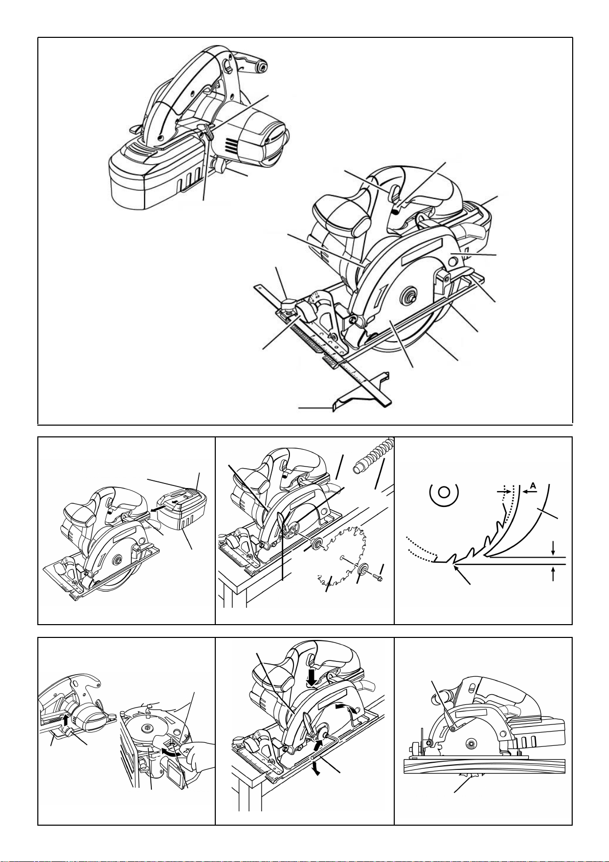
Fig. 1
Fig. 2
Fig. 3
Fig. 3a
Fig. 3b
Fig. 4
Fig. 5
A
C
B
D
E
F
G
H
I
J
K
L
M
N
O
A
D
B
C
A
B
C
D
E
F
G
I
H
C
D
B
A
B
C
E
D
A
B
A
B
Page 4
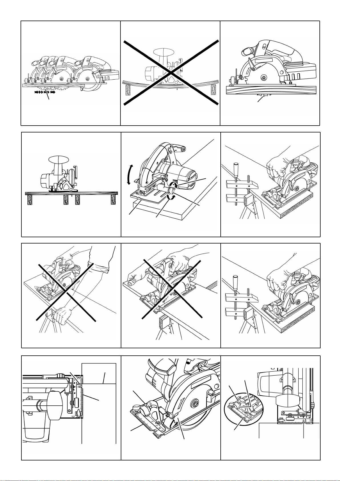
Fig. 6
Fig. 7
Fig. 8
Fig. 9
Fig. 10
Fig. 11
Fig. 12
Fig. 13
Fig. 14
Fig. 15
Fig. 16
Fig. 17
A
B
A
A
A
A
B
C
D
E
F
A
A
A
A
A
BC
D
A
B
C
A
B
C
D
Page 5
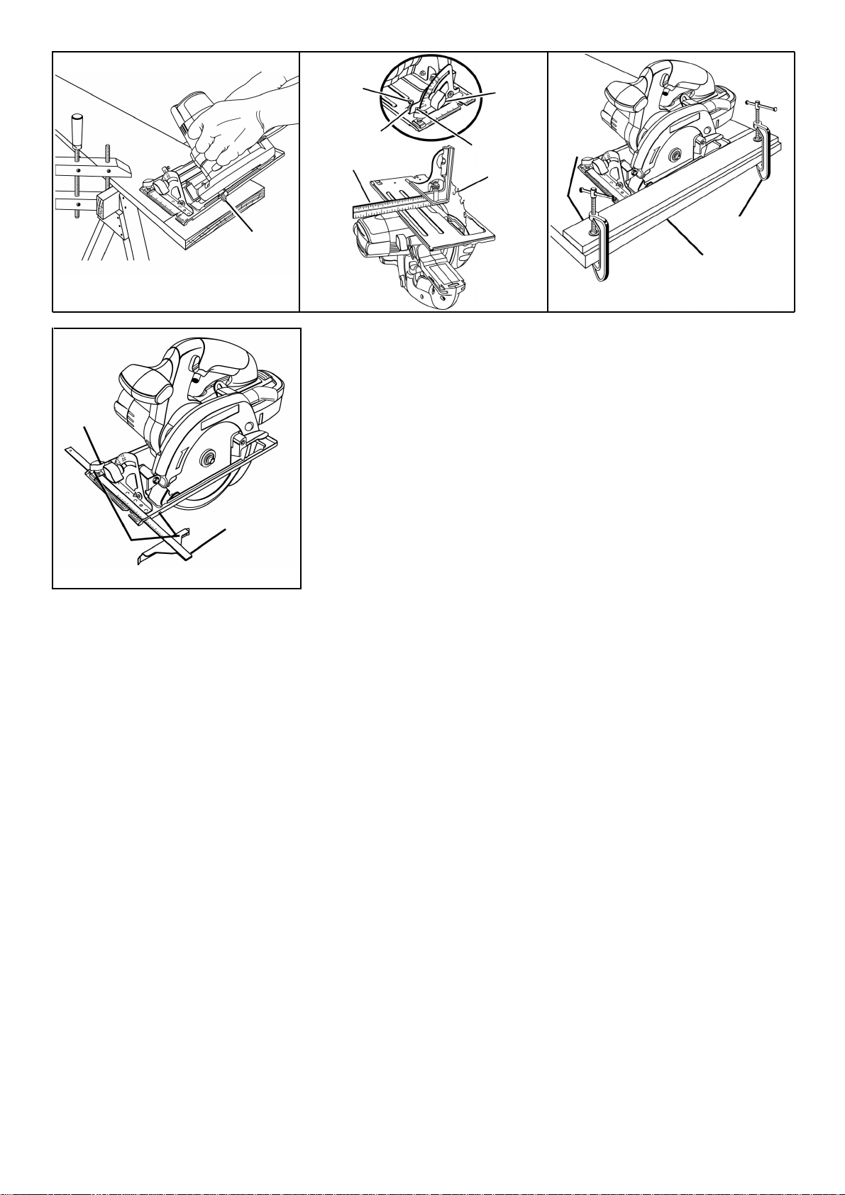
Fig. 18
Fig. 19
Fig. 20
Fig. 21
A
A
B
C
D
E
F
A
B
C
A
B
C
Page 6
18
1. INTRODUCTION
Y our circular saw has many features to optimise your cutting operations. Safety, performance and dependability have been
given top priority in the design of this tool making it easy to maintain and operate.
WARNING:
Look for this symbol which points out important safety precautions. It is used to attract your attention. Your safety is
at risk!!!
CAUTION: Carefully read through this entire owner's manual before using your new circular saw. Pay close attention
to the Rules For Safe Operation, Warnings and Cautions. If you use your circular saw properly and only for what it
is intended, you will enjoy years of safe, reliable service.
2. ACCESSORIES
The following recommended accessories were available at the time this manual was printed.
• 165mm (6 1/2") thin kerf blade
WARNING:
The operation of any power tool can result in foreign objects being thrown into your eyes, which can
result in severe eye damage. Before you start using your tool, always wear safety goggles or safety
glasses with side shields and a full face dust mask when needed. We recommend a safety mask for
use over eyeglasses or standard safety glasses with side shields.
3. RULES FOR SAFE OPERATION OF THIS TOOL
The purpose of safety symbols is to attract your attention to possible dangers. Pay careful attention to the safety
symbols and accompanying explanations. The safety warnings do not by themselves eliminate any danger.
The instructions or warnings they give are not substitutes for proper accident prevention measures.
SYMBOL MEANING
SAFETY ALERT SYMBOL:
Indicates danger, warning or caution. May be used in conjunction with other symbols or pictographs.
DANGER: Failure to obey a safety warning can result in serious injury to yourself or to others.
Always follow the safety precautions scrupulously to reduce the risk of fire, electric shock and
personal injury.
WARNING: Failure to obey a safety warning can result in serious injury to yourself or to others.
Always follow the safety precautions scrupulously to reduce the risk of fire, electric shock and
personal injury.
CAUTION: Failure to obey a safety warning may result in property damage or personal injury to
yourself or to others. Always follow the safety precautions scrupulously to reduce the risk of fire,
electric shock and personal injury.
NOTE: Gives you information or instructions vital to the operation or maintenance of the equipment.
MEANING OF SAFETY SIGNS ON PRODUCT
Read the operation manual and follow all warnings and safety instructions.
Wear eye protection and ear protection.
Do not use this machine in damp weather conditions!
Risk of cut or shock - keep hands away from the blade.
GB
Page 7

19
WARNING:
Do not attempt to use this tool until you have fully read and understood all instructions and safety rules contained in
this manual. Failure to comply with these rules and instructions can result in accidents such as fire, electric shock,
or serious personal injury. Save this user’s manual and refer to it frequently for continuing safe operation and to
instruct others who may use this tool.
READ ALL INSTRUCTIONS
• KNOW YOUR POWER TOOL. Read the owner's manual carefully. Learn its applications and limitations as well as the
specific potential hazards related to this tool.
• GUARD AGAINST ELECTRICAL SHOCKby preventing body contact with earthed surfaces. For example: pipes, radiators,
ranges, cookers or refrigerators.
• KEEP WORK AREA CLEAN. Cluttered work areas invite accidents.
• AVOID DANGEROUS ENVIRONMENTS.Do not use the power tool in damp or wet locations or places exposed to rain.
Keep work area well lit.
• KEEP CHILDREN AND VISITORS AW AY. All visitors should wear safety glasses and be kept a safe distance from the
work area. Do not let visitors touch the tool.
• PUT UNUSED TOOLS A WAY. When not in use, tools should be stored in a dry locked-up place, out of children’s reach.
• DO NOT FORCE YOUR TOOL. Your tool will be more efficient and safer when used at the rate for which it was intended.
• USE THE RIGHT TOOL. Do not force small tools to do the job of a heavy-duty tool. Do not use your tool for a purpose
not intended. For example, a circular saw should never be used for cutting tree limbs or logs.
• WEAR PROPER CLOTHES. Do not wear loose clothing or jewellery that can get caught in the tool's moving parts and
cause personal injury. Rubber gloves and non-skid footwear are recommended when working outdoors. W ear protective
hair covering to contain long hair and keep it from being drawn into air vents.
• ALW A YS WEAR SAFETYGLASSES. Ordinary eyeglasses have only impact-resistant lenses; they are NOT safety glasses.
• PROTECT YOUR LUNGS. Wear a face mask or dust mask if the cutting operation generates dust.
• PROTECT YOUR EARS. Wear ear protectors during extended periods of operation of your tool.
• SECURE YOUR WORKPIECE. Use clamps or a vice to hold down your workpiece. It's safer than using your hand and
it frees both hands to operate the tool.
• KEEP YOUR BALANCE. Keep proper footing and balance at all times. Do not use your tool while standing on a ladder
or any other unstable support.
• MAINTAIN TOOLS IN GOOD WORKING CONDITION. Keep tools sharp at all times, and clean for best and safest
performance. Follow instructions for lubricating and changing accessories.
• REMOVE ADJUSTING KEYS AND SP ANNERS. Get into the habit of checking that adjusting keys and spanners have
been removed from the machine before turning it on.
• NEVER USE YOUR TOOL IN AN EXPLOSIVE ENVIRONMENT.
Normal sparking of the motor could ignite flammable liquids, gases, or fumes.
• KEEP HANDLES CLEAN AND FREE FROM OIL AND GREASE. Always use a clean cloth to clean your tool. Never
use brake fluid, petroleum-based products or any strong solvents to clean your tool.
• STAY ALERT. Watch what you are doing and use common sense. Do not operate your tool when you are tired. Do not
rush.
• CHECK THAT NO PART OR ACCESSORY IS DAMAGED. Before using your tool, make sure that any damaged part
(the blade guard for instance) will be able to continue working or fulfilling its function. Check the alignment of moving
parts. Check that no part is broken. Check the mounting and any other aspect that may affect tool operation. Aguard
or other part that is damaged should be properly repaired or replaced by a Ryobi Authorised Service Centre unless otherwise
indicated in this instruction manual.
• DO NOT USE THE TOOL IF THE SWITCH DOES NOT TURN IT ON AND OFF. Have defective switches replaced by
a Ryobi Authorised Service Centre.
• DRUGS, ALCOHOL, MEDICATION. Do not operate your tool while under the influence of drugs or alcohol, or if you
are taking medication.
• CUTTING INTO ELECTRICAL WIRING IN WALLS AND FLOORS CAN CAUSE THE BLADE AND METAL PARTS
TO BECOME LIVE. Do not touch the metal parts when cutting into walls and floors; grasp only the insulated handle(s)
of the tool. Make sure there are no hidden electrical wires, water pipes, or metal framework in the blade path when cutting
into a wall or floor.
• Inspect for and remove all nails from lumber before cutting.
IMPORTANT SAFETY RULES FOR BATTERY-POWERED TOOLS
• Keep in mind that battery-powered tools are always ready to be used since they do not have to be plugged into an electrical
outlet. Be aware of possible hazards when carrying your battery-operated tool, when making adjustments to it, or when
changing accessories.
• USE ONLY THE CHARGER PROVIDED WITH YOUR BATTERY PACK. Do not replace the original charger with any
other charger. The use of another charger could cause batteries to explode and result in serious personal injury.
GB
Page 8

20
• DO NOT PLACE BATTERY-OPERATED TOOLS OR THEIR BATTERIES NEAR FIRE OR A HEAT SOURCE. They
may explode.
• DO NOT CHARGE A BATTERY-OPERATED TOOL IN A DAMP OR WET LOCATION.
• Your battery-operated tool should be charged in a location where the temperature is between 50°F (10°C) and 104°F
(40°C)
• Under extreme usage or temperature conditions, battery leakage may occur. If the battery liquid comes into contact with
your skin, wash immediately with soap and water, then neutralise with lemon juice or vinegar. If the liquid gets in your
eyes, flush them out with clean water for at least 10 minutes, then seek immediate advice from a doctor or the emergency
services.
• When carrying your battery-operated tool, make sure it is not running and your finger is not on the switch. Avoid
unintentional starting.
• SECURE YOUR WORKPIECE PROPERL Ybefore starting your tool. NEVER hold the workpiece in your hand or between
your legs.
• FOR MAINTENANCE PURPOSES, USE ONLY IDENTICAL REPLACEMENT PARTS.
IMPORTANT SAFETY INSTRUCTIONS FOR CIRCULAR SAWS
• MAKE SURE THAT BLADE GUARDS ARE ALWAYS IN PLACE AND IN PROPER WORKING ORDER. Never wedge
or tie the lower blade guard open. Before you use your tool, always check that the lower blade guard is operating
properly. Do not use it if the lower blade guard does not close briskly over the saw blade.
WARNING:
If the saw is dropped, the lower blade guard or riving knife may get twisted, restricting full return. If the lower blade
guard or riving knife becomes twisted or damaged, replace it before using the tool.
• Ensure that the riving knife is adjusted so that:
- the distance between the riving knife and the teeth of the saw blade is under 5 mm
- the teeth do not extend more than 5 mm beyond the lower edge of the riving knife. (See Figure 3a.)
• KEEP BLADES CLEAN AND SHARP. Sharp blades minimise stalling and kickback.
• KEEP HANDS AWAY FROM THE CUTTING AREA. Keep hands away from the blade. Do not reach underneath the
workpiece while the blade is rotating. Do not attempt to remove cut material when the blade is moving.
WARNING:
Blades coast for a little while after turn off.
• USE A RIP FENCE. Always use a fence or straight edge guide when ripping.
• SUPPORT LARGE PANELS. To minimise the risk of blade pinching or kickback, always support large panels as shown
in Figure 9. When the cutting operation requires the resting of the saw on the workpiece, the saw should be rested on
the larger portion and the smaller piece cut off.
WARNING:
If the lower blade guard must be raised to make a cut, always raise it with the retracting handle to avoid serious injury.
• GUARD AGAINST KICKBACK. Kickback occurs when the saw jams up suddenly and is then driven back towards the
operator. Release the switch immediately if the blade binds or if the saw jams up. Do not remove the saw from the
workpiece while the blade is moving.
• BEFORE MAKING ACUT, MAKE SURE THE DEPTH AND BEVELADJUSTMENT KNOBS ARE TIGHTL YSCREWED ON.
• USE ONLY CORRECT BLADES. Do not use blades with incorrect size bore holes. Never use blade washers or bolts
that are defective or incorrectly adjusted. The maximum blade diameter is 165 mm and the thickness of the teeth must
not exceed 1.5 mm.
• Do not use blades which are damaged or deformed.
• Do not use blades made of high speed steel.
• Do not use blades which do not comply with the specifications given in this manual.
• Do not stop the blade by lateral pressure on the disc.
• Ensure that the moving guards operate freely without jamming.
• Do not lock the moving guards in the open position.
• Ensure that all parts of the retraction mechanism on the guard system operate correctly.
• Remove the battery pack before replacing the blade, making adjustments, or other maintenance work.
• Using manufacturer data
- ensure that the diameter, thickness and other characteristics of the saw blade are suitable for the tool
- ensure that the saw blade is suitable for the spindle speed of the tool.
Do not use saw blades with a thicker body or smaller tooth set than the thickness of the riving knife.
• NEVER touch the blade or other moving parts during use.
• NEVER start the saw when its blade is touching the workpiece.
GB
Page 9

21
• NEVER lay a tool down before its moving parts have come to a complete stop.
• AVOID UNINTENTIONALST ARTING:Do not carry a battery-operated tool with a finger on the trigger. Ensure that the
tool is in the off position when sliding-in the battery.
• SAVE THESE INSTRUCTIONS. Refer to them frequently and use them to instruct others who may use this tool. If you
loan someone this tool, loan them these instructions also.
SAVE THESE INSTRUCTIONS.
4. UNPACKING
Y our circular saw has been shipped completely assembled except for the blade. Inspect it carefully to make sure no breakage
or damage has occurred during shipping. If any parts are damaged or missing, contact your nearest Ryobi Authorised
Service Centre to obtain replacement parts before attempting to operate the saw. A blade, blade key, and this operator's
manual are also included.
WARNING:
If any part is missing, do not operate this tool until the missing part has been replaced. Failure to do so could result
in serious personal injury.
5. MACHINE SPECIFICATIONS
Blade Diameter 165 mm (6 1/2")
Blade Arbor 16 mm
Cutting Depth at 0° 53.5 mm
Cutting Depth at 45∞ 42 mm
No Load Speed 2,500 min
-1
Motor 18 V DC
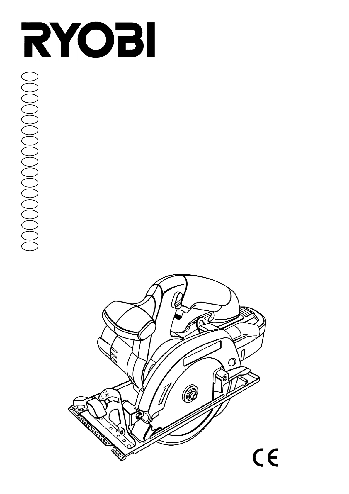
6. FEATURES
6.1 KNOW YOUR CORDLESS CIRCULAR SAW
Before attempting to use a tool, familiarise yourself with all its operating features and specific safety requirements.
Features include easily operated bevel cut and depth of cut adjustment mechanisms, positive 0° bevel stop, spindle lock,
and blade key storage compartment.
Fig. 1:
A. BLADE KEY (5 mm HEX KEY)
B. DEPTH OF CUT ADJUSTMENT (DEPTH ADJUSTMENT KNOB)
C. BLADE KEY STORAGE AREA
D. LOCK-OFF BUTTON
E. TRIGGER SWITCH
F. BATTERY PACK
G. UPPER BLADE GUARD
H. LOWER BLADE GUARD LEVER
I. BASE ASSEMBLY
J. LOWER BLADE GUARD
K. BLADE
L. RIP GUIDE
M. BEVEL CUT ADJUSTMENT (BEVEL ADJUSTMENT KNOB)
N. OPTIONALRIP GUIDE SCREW (WING SCREW)
O. SPINDLE LOCK BUTTON
6.2 APPLICATIONS
(Only use your saw for the purpose listed below)
• Cutting all types of wood products (lumber, plywood, panelling).
6.3 TRIGGER SWITCH
Y our saw is equipped with a lock-off button which reduces the possibility of accidental starting. The lock-off button is located
on the handle above the trigger switch. You must depress the lock-off button in order to pull the trigger switch. The lock
resets each time the trigger is released.
NOTE: You can depress the lock-off button from either the left or right side.
GB
Page 10

22
7. OPERATION
WARNING:
Always wear safety goggles or safety glasses with side shields when operating tools. Failure to do so could result
in objects being thrown into your eyes, and cause serious eye injury.
WARNING:
Do not allow familiarity with your cordless circular saw to make you careless. Remember that a careless fraction of
a second is sufficient to inflict severe injury.
WARNING:
Always remove the battery pack from your saw when you are assembling parts, making adjustments, attaching or
removing a blade, cleaning, or when you are not using your saw. Removing the battery pack will prevent accidental
starting that could cause serious personal injury.
7.1 TO REMOVE THE BATTERY PACK
• Depress the release button and slide out the battery pack. See Figure 2.
• Remove the battery pack from your saw.
WARNING:
Failure to remove the battery pack from the saw could result in accidental starting causing possible serious personal
injury.
7.2 TO INSTALL THE BATTERY PACK
• Slide-in the battery pack.
• Make sure the latch of your battery pack snaps into place and the battery pack is secured in the saw before beginning
operation.
CAUTION:
When placing the battery pack in your saw, make sure the battery pack snaps properly into place. Improper assembly
of the battery pack can cause damage to internal components.
WARNING:
The maximum diameter of the saw blade is 165 mm. Never use a blade that is too thick to allow the outer blade washer
to engage with the flat on the spindle. Larger blades will touch the blade guard, while thicker blades will prevent the
blade screw from securing the blade on the spindle. Either of these situations could result in a serious accident.
Fig. 2:
A. DEPRESS LATCH TO RELEASE BATTERY PACK
B. LATCH
C. GROOVES
D. BATTERY PACK
7.3 TO ATTACH OR REMOVE THE BLADE
7.3.1 TO ATTACH THE BLADE:
• Remove battery pack from saw.
WARNING:
Failure to remove the battery pack from the saw could result in accidental starting and cause serious personal injury.
• Depress latch on end of battery pack and release it from your saw. See Figure 2.
• Remove blade key (5 mm hex key) from its storage compartment. See Figure 1.
• Depress spindle lock button and remove blade screw and outer blade washer. See Figure 3.
NOTE: Turn blade screw clockwise to remove it.
• Put a drop of oil onto inner blade washer and outer blade washer where they touch the blade.
WARNING:
If the inner blade washer has been removed, put it back in place before placing the blade on the spindle. Failure to
do so could cause an accident since the blade will not tighten properly.
• Fit saw blade inside blade guard and onto spindle.
NOTE: The saw teeth point upwards at the front of saw as shown in Figure 3.
• Put outer blade washer back in place.
GB
Page 11

23
• Depress spindle lock button, then replace blade screw.
Tighten blade screw securely.
NOTE: Turn blade screw anticlockwise to tighten.
• Return blade key to storage compartment.
REMEMBER: Never use a blade that is too thick to allow the outer blade washer to engage with the flat on the
spindle.
7.3.2 TO CONNECT EXTERNAL DUST COLLECTION EQUIPMENT:
• Connect the hose connector of vacuum cleaner to the dust pipe joint.
Fig. 3:
A. SPINDLE LOCK BUTTON
B. DUST PIPE JOINT
C. SPINDLE
D. HOSE CONNECTOR
E. BLADE SCREW
F. OUTER BLADE WASHER
G. BLADE
H. LOWER BLADE GUARD LEVER
I. INNER BLADE WASHER
7.3.3 ADJUSTING THE RIVING KNIFE (Fig. 3a, 3b)
• Never use saw blades with a thicker body or smaller tooth set than the thickness of the riving knife.
• Ensure that the riving knife is adjusted so that: ( Fig.3a)
A The distance between the riving knife and the toothed rim of the saw blade is under 5 mm.
B. The toothed rim does not extend more than 5 mm beyond the lower edge of the riving knife.
• The riving knife must always be used.
• Loosen the depth adjustment knob and slide the base assembly as far as possible. (Fig.3b)
• Loosen the hex. socket head bolt with the blade key. (Fig.3b)
• Adjust the clearance of the riving knife and the tip of the saw blade.
• Tighten the hex. socket head bolt securely after adjustment.
Fig. 3a:
C. RIVING KNIFE
D. TOOTHED RIM
Fig. 3b:
A. BLADE KEY
B. HEX. SOCKET HEAD BOLT
C. RIVING KNIFE
D. BASE ASSEMBLY
E. DEPTH ADJUSTMENT
7.3.4 TO REMOVE THE BLADE
• Remove the battery pack from the saw.
WARNING:
Failure to remove the battery pack from the saw could result in accidental starting and cause serious personal injury.
• Remove the blade key from its storage compartment. See Figure 1.
• Position your saw as shown in Figure 4, depress spindle lock button, and remove blade screw.
NOTE: Turn blade screw clockwise to remove.
• Remove outer blade washer. See Figure 3.
NOTE: The blade can be removed at this point.
7.4 SAW BLADES
The best of saw blades will not cut efficiently if they are not kept clean, sharp, and properly set. Using a dull blade will place
a heavy load on your saw and increase the risk of kickback. Keep extra blades on hand, so that sharp blades are always
available.
Resin hardened on blades will slow your saw down. Use resin remover, hot water , or paraf fin to remove these accumulations.
DO NOT USE PETROL.
GB
Page 12

24
7.5 BLADE GUARD SYSTEM
The lower blade guard attached to your cordless circular saw is there for your protection and safety . It should never be altered
for any reason. If it becomes damaged or begins to return slowly or sluggishly, do not operate your saw until the guard has
been repaired or replaced. Always leave the guard in operating position when using the saw.
DANGER:
When sawing through a workpiece, the lower blade guard does not cover the blade on the underside of the workpiece. Since the blade is exposed on the underside of the workpiece, keep hands and fingers away from the cutting
area. Because of the risk of serious bodily injury, the rotating blade must never come into contact with any part of
your body. See Figure 5.
Never use your saw when the guard is not operating correctly. The guards should be checked for correct operation
before each use. If you drop your saw, check the lower blade guard and riving knife for damage at all depth settings
before using it again.
NOTE: The guard is operating correctly when it moves freely and readily returns to the closed position. If for any
reason your lower blade guard does not close freely, take it to the nearest Ryobi Authorised Service Centre to have
it repaired.
Fig. 5:
A. LOWER BLADE GUARD IS IN UP POSITION WHEN MAKING ACUT
B. BLADE EXPOSED ON UNDERSIDE OF WORKPIECE
7.6 KICKBACK
See Figure 6.
The best guard against kickback is to avoid dangerous practices.
Kickback occurs when the saw jams up suddenly and the saw is driven back towards the operator. Blade jamming occurs
when the blade is pinched in the wood.
DANGER:
Release the switch immediately if the blade binds or if the saw jams up. Kickback could cause you to lose control of
your saw. Loss of control can lead to serious injury.
KICKBACK IS CAUSED BY:
• Incorrect blade depth setting. See Figure 6.
• Sawing into knots or nails in workpiece.
• Twisting blade while making a cut.
• Making a cut with a dull, gummed up, or improperly set blade.
• Incorrectly supported workpiece. See Figure 7.
• Forcing a cut
• Cutting warped or wet lumber.
• Tool misuse or non compliance with operating procedures.
TO MINIMISE THE RISK OF KICKBACK:
• Always keep the correct blade depth setting – this should not exceed 6 mm (1/4'') below the material to be cut. See Figure
8. For efficient cutting, a single blade tooth should protrude below the material to be cut.
• Inspect the workpiece for knots or nails before beginning a cut. Never saw into a knot or nail.
• Make straight cuts. Always use a straight edge guide when making rip cuts. This helps prevent twisting of the blade.
• Always use clean, sharp and properly set blades. Never cut with dull blades.
• T o avoid pinching the blade, support the workpiece properly before beginning a cut. The right and wrong ways to support
large pieces of work are shown in Figures 7 and 9.
• When making a cut, use steady, even pressure. Never force cuts.
• Do not cut warped or wet lumber.
• Always hold your saw firmly with both hands and keep your body in a balanced position so as to resist the forces of
kickback should it occur.
When using your saw, always stay alert and in control of your tool. Do not remove your saw from the workpiece
while the blade is moving.
Fig. 6:
A. KICKBACK
B. BLADE SET TOO DEEP
Fig. 7:
A. WRONG
GB
Page 13

25
Fig. 8:
A. CORRECT BLADE DEPTH SETTING = ONE BLADE TOOTH PROTRUDING BELOW THE MATERIAL TO BE CUT
Fig. 9:
A. RIGHT
7.7 DEPTH OF CUT
Always keep correct blade depth. This should not exceed 6 mm (1/4 '') below the material to be cut. Adeeper blade setting
will increase the risk of kickback and cause the cut to be rough. For efficient cutting, a single blade tooth should protrude
below the material to be cut.
7.8 TO ADJUST BLADE DEPTH
• Remove battery pack from saw.
WARNING:
Failure to remove the battery pack from your saw could result in accidental starting and cause serious personal injury.
• Loosen the depth adjustment knob. See Figure 10.
• Hold the base flat against the workpiece and raise or lower the saw until the required depth is reached.
• Tighten the depth adjustment knob securely.
Fig. 10:
A TO TIGHTEN
B. DEPTH ADJUSTMENT KNOB
C. TO LOOSEN
D. BASE ASSEMBLY
E. TO LOWER SAW
F. TO RAISE SAW
7.9 STARTING ACUT
Know the right way to use your saw.
See Figure 11.
Never use your saw as shown in Figure 12.
Never place your hand on the workpiece behind your saw while making a cut.
WARNING:
To make sawing easier and safer, always maintain proper control of your saw. Loss of control of your saw could
cause an accident and result in serious injury.
Fig. 11:
A. RIGHT
Fig. 12:
A. WRONG
7.10 TO MAINTAIN OPTIMUM CONTROL
• Always support your workpiece near the cut.
• Support your workpiece so the cut will be on your left.
• Clamp your workpiece so it will not move during the cut.
Place your workpiece with its good side down.
NOTE: The good side is the side on which appearance is important.
Before beginning a cut, draw a guide line along the desired line of cut. Then place the front edge of the base on the part of
your workpiece that is solidly supported. See Figure 11.
Never place your saw on the part of the workpiece that will fall off when the cut is made. See Figure 13.
Hold your saw firmly with both hands.
See Figure 14.
Depress the lock-off button and squeeze the trigger to start your saw. Always let the blade reach full speed, then insert your
saw into the workpiece.
WARNING:
The blade must not come into contact with the workpiece before it reaches full speed. Otherwise your saw could kick
back towards you resulting in serious injury.
GB
Page 14

26
When making a cut, use steady, even pressure. Forcing causes rough cuts, could shorten the life of your saw and could
cause "kickback".
DANGER:
When sawing through a workpiece, the lower blade guard does not cover the blade which is thus exposed on the
underside of the workpiece. Keep your hands and fingers away from the cutting area. Because of the risk of serious
bodily injury, the rotating blade must never come into contact with any part of your body.
Once you have completed your cut, release the trigger and allow the blade to come to a complete stop. Do not remove
your saw from the workpiece while the blade is moving.
CAUTION:
To make sawing easier and safer, always maintain proper control of your saw. Loss of control of your saw could
cause an accident and result in serious injury.
Fig. 13:
A. WRONG
Fig. 14:
A. RIGHT
7.11 CROSS CUTS AND RIP CUTS
When making a cross cut or rip cut, align your line of cut with the outer blade guide notch on the saw base as shown in Figure
15.
Since blade thickness varies, always make a trial cut on scrap material along a guide line to determine whether the guide
line must be offset and, if so, by how much to produce an accurate cut.
NOTE: The distance between the line of cut and the guide line is the amount you should offset the guide line on the workpiece.
Fig. 15:
ALIGN OUTER BLADE GUIDE NOTCH ON SAW BASE WITH LINE OF CUTAS SHOWN WHEN MAKING CROSS CUTS
OR RIP CUTS
A. TOP VIEW OF SAW
B. BLADE GUIDE NOTCH
C. GUIDE LINE
D. FRONT OF SAW
7.12 WIDTH OF CUT SCALE
See Figure 16.
Awidth-of-cut scale has been provided on the base of your saw. When making straight cross cuts or rip cuts, the scale can
be used to measure up to 110 mm on the right side of the blade and up to 25 mm on the left side of the blade.
Fig. 16:
A. BASE ASSEMBLY
B. BLADE
C. WIDTH-OF-CUT SCALE
7.13 BEVEL CUTS
The angle of cut of your saw may be adjusted to any desired setting between zero and 50°. NOTE: When making 50° cuts,
the blade should be set at the maximum depth of cut.
When making 45° bevel cuts, there is a notch in the saw base to help you line up the blade with the guide line. See Figure 17.
When making 45° bevel cuts, line up your guide line with the guide notch on the saw base.
Since blade thickness varies and different angles require different settings, always make a trial cut on scrap material
along a guide line to determine how much you should offset the guide line on the board to be cut.
When making a bevel cut, hold your saw firmly with both hands as shown in Figure 18.
Rest the front edge of the base on the workpiece. Depress the lock-off button and squeeze the trigger to start your saw.
Always let the blade reach full speed, then insert your saw into the workpiece.
WARNING:
The blade must not come into contact with the workpiece before it reaches full speed. Otherwise your saw could kick
back towards you resulting in serious injury.
Once you have completed your cut, release the trigger and allow the blade to come to a complete stop. After the blade has
stopped, lift your saw from the workpiece.
GB
Page 15

27
Fig. 17:
WHEN MAKING 45° BEVEL CUTS, ALIGN INNER BLADE GUIDE NOTCH ON SAW BASE WITH GUIDE LINE
A. BEVEL SCALE
B. BEVELADJUSTMENT KNOB
C. GUIDE LINE
D. BLADE GUIDE NOTCH
Fig. 18:
A. LOWER BLADE GUARD
7.14 TO ADJUST BEVEL SETTING
• Remove battery pack from saw.
WARNING:
Failure to remove the battery pack from the saw could result in accidental starting and cause serious personal injury.
• Loosen bevel adjustment knob. See Figure 17.
• Raise motor housing end of saw until you reach desired angle setting on bevel scale. See Figure 17.
• Tighten bevel adjustment knob securely.
WARNING:
Attempting to do a bevel cut without the knob securely tightened could result in serious injury.
7.15 POSITIVE 0° BEVEL STOP
See Figure 19.
Your saw has a positive 0° bevel stop, that has been factory set to ensure that your saw blade is at 0° when making 90°
cuts. However, misalignment can occur during shipping.
7.16 TO CHECK
• Remove battery pack from saw.
WARNING:
Failure to remove the battery pack from the saw could result in accidental starting and cause serious personal injury.
• Place your saw in upside down position on workbench. See Figure 19.
• Using a carpenter's square, check squareness of saw blade to the base of your saw.
7.17 TO ADJUST
• Remove battery pack from saw.
WARNING:
Failure to remove the battery pack from the saw could result in accidental starting and cause serious personal injury.
• Loosen bevel adjustment knob.
• Loosen hex nut securing adjustment screw.
• Turn screw and adjust base until square with saw blade.
• Tighten hex nut and bevel adjustment knob securely.
WARNING:
Attempting to make cuts without bevel adjustment knob securely tightened can result in serious injury.
WARNING:
Never tie the lower blade guard in a raised position. Do not leave the blade exposed as this could lead to serious
injury.
Fig. 19:
A ADJUSTMENT SCREW
B. BEVELADJUSTMENT KNOB
C. POSITIVE 0° BEVEL STOP
D. BLADE
E. CARPENTER'S SQUARE
F. HEX NUT
GB
Page 16

28
7.18 RIP CUTS
OPTIONAL RIP FENCE (EDGE GUIDE)
See Figure 20.
Use a guide when making long or wide rip cuts with your saw. You can make an efficient rip fence by clamping a straight
edge to your workpiece. Secure the workpiece. Using C-clamps, firmly clamp a straight edge to the workpiece and guide
the saw along the straight edge to achieve a straight rip cut. Do not bind the blade in the cut. If using the optional rip fence,
see the following instructions and Figure 20.
Fig. 20:
ALTERNATIVE METHOD FOR RIP CUTTING
A. STRAIGHT EDGE
B. C-CLAMPS
C. WORKPIECE
7.19 TO ASSEMBLE RIP FENCE
See Figure 21.
• Remove battery pack from saw.
WARNING:
Failure to remove the battery pack from the saw could result in accidental starting and cause serious personal injury.
• Place rip fence through holes in saw base as shown in Figure 21.
• Adjust rip fence to the width needed.
• Tighten rip fence screw (wing screw) securely.
When using a rip fence, position the face of the rip fence firmly against the edge of the workpiece. This makes for a true
cut without pinching the blade. The guiding edge of the workpiece must be straight for your cut to be straight. Use caution to
prevent the blade from binding in the cut.
Fig. 21:
A. RIP FENCE SCREW (WING SCREW)
B. RIP FENCE (EDGE GUIDE)
C. PLACE RIP FENCE THROUGH HOLES
8. MAINTENANCE
WARNING:
Only identical spare parts must be used as replacement parts. The use of any other spare part may create a hazard
or damage your tool.
WARNING:
Do not at any time let brake fluid, petrol, petroleum-based products, penetrating oils, etc. come in contact with the
plastic parts. These chemicals contain substances that can damage, weaken or destroy plastic.
DO NOT abuse your tools. Abusive practices can damage your tool as well as your workpiece.
If the saw is accidentally dropped, the dust pipe joint may come off. Just snap it into the upper guard.
WARNING:
Do not attempt to modify this tool or create accessories not recommended for use with this tool. Any such alteration
or modification is deemed as misuse and could result in hazardous situations leading to possible serious personal
injury.
GB
Page 17

Niveau de pression acoustique 90,9 dB(A)
Niveau de puissance acoustique 103,9 dB(A)
Valeur d'accélération de la moyenne quadratique pondérée 0,65 m/s
2
Sound pressure level 90.9 dB(A)
Sound power level 103.9 dB(A)
Weighted root mean square acceleration value 0.65 m/s
2
Schalldruckpegel 90,9 dB(A)
Schallleistungspegel 103,9 dB(A)
Beschleunigung des quadratischen gewogenen Mittelwerts 0,65 m/s
2
Nivel de presión acústica: 90,9 dB(A)
Nivel de potencia acústica: 103,9 dB(A)
Valor de aceleración de la media cuadrática ponderada: 0,65 m/s
2
Livello di pressione acustica 90,9 dB(A)
Livello di potenza acustica 103,9 dB(A)
Valore d’accelerazione della media quadratica ponderata 0,65 m/s
2
Nível de pressão acústica 90,9 dB(A)
Nível de potência acústica 103,9 dB(A)
Valor da aceleração da média quadrática ponderada 0,65 m/s
2
Geluidsdrukniveau 90,9 dB(A)
Geluidsvermogensniveau 103,9 dB(A)
Versnellingswaarde van de gewogen effectieve waarde 0,65 m/s
2
Ljudtrycksnivå 90,9 dB(A)
Ljudeffektnivå 103,9 dB(A)
Accelerationsvärde på viktat kvadratiskt medeltal 0,65 m/s
2
Lydtryksniveau 90,9 dB(A)
Lydstyrkeniveau 103,9 dB(A)
Accelerationsværdi for vægtet kvadratmiddeltal 0,65 m/s
2
Lydtrykknivå 90,9 dB(A)
Lydstyrkenivå 103,9 dB(A)
Veid kvadratisk middelverdi av akselerasjonsverdien 0,65 m/s
2
Äänenpainetaso 90,9 dB(A)
Äänen tehotaso 103,9 dB(A)
Painotettu kiihdytyksen tehollisarvo 0,65 m/s
2
Επίπεδο ακουστικής πίεσης 90,9 dB(A)
Επίπεδο ακουστικής ισχύος 103,9 dB(A)
Ενεργς τιµή επιτάχυνσης σταθµισµένου µέσου ρου 0,65 m/max.
Hangnyomás szint : 90,9 dB(A)
HangerΠszint : 103,9 dB(A)
A gyorsítás kiegyensúlyozott négyzetes átlag értéke : 0,65 m/s
2
Hladina akustického tlaku 90,9 dB (A)
Hladina akustického v˘konu 103,9 dB (A)
VáÏená efektivní hodnota zrychlení 0,65 m/s
2
мУ‚ВМ¸ ‡ННЫТЪЛ˜ВТНУ„У ‰‡‚ОВМЛfl 90,9 dB(A)
мУ‚ВМ¸ ‡ННЫТЪЛ˜ВТНУИ ПУ˘МУТЪЛ 103,9 dB(A)
ЗВОЛ˜ЛМ‡ ЫТНУВМЛfl ТВ‰МВИ ЫПВВММУИ Н‚‡‰‡ЪЛ˜ВТНУИ 0,65 П/ТВН
2
Nivel de presiune acustică 90,9 dB(A)
Nivel de putere acustică 103,9 dB(A)
Valoarea acceleraţiei medie pătratică ponderată. 0,65 m/s
2
Poziom ciÊnienia akustycznego 90,9 dB(A)
Poziom mocy akustycznej 103,9 dB(A)
WartoÊç skuteczna przyspieszenia Êrednia kwadratowa wa˝ona 0,65 m/s
2
F
GB
D
E
I
P
NL
S
DK
N
FIN
GR
HU
CZ
RU
RO
PL
Page 18

Name/Title: Michel Violleau
Président/Directeur Général
Signature:
Name of company: RYOBI TECHNOLOGIES S.A.
Address: Z.I. PARIS NORD II
209, RUE DE LA BELLE ÉTOILE
95700 ROISSY EN FRANCE
FRANCE
Name of company: Ryobi Technologies (UK) Ltd.
Address: Anvil House, Tuns Lane,
Henley-on-Thames,
Oxfordshire, RG9 1SA
United Kingdom
Name of company: Ryobi Technologies GmbH
Address: Itterpark 9
D-40724 Hilden
Germany
Name/Title: Derrick Marshall
General Manager
Signature:
Name/Title: Walter Martin Eichinger
General Manager
Signature:
Machine: 165mm (6 1/2”) CORDLESS CIRCULAR SAW / Type: CW-1801/165 CW-1801
F
GB
D
E
P
NL
S
DK
N
FIN
GR
CE DÉCLARATION DE CONFORMITÉ
Nous déclarons sous notre propre responsabilité que ce produit
est en conformité avec les normes ou documents normalisés
suivants :
EN60335, EN55014, EN61000, 89/336/EEC, 73/23/EEC
CE DECLARATION OF CONFORMITY
We declare under our sole responsibility that this product is in
conformity with the following standards or standardized documents.
EN60335, EN55014, EN61000, 89/336/EEC, 73/23/EEC
CE KONFORMITÄTSERKLÄRUNG
Wir erklären in alleiniger Verantwortung, dass dieses Produkt
mit den folgenden Normen oder normativen Dokumenten übereinstimmt: “EN60335, EN55014, EN61000”
Gemäß den Bestimmungen der Richtlinien "89/336/EWG,
73/23/EWG"
CE DECLARACIÓN DE CONFORMIDAD
Declaramos bajo nuestra exclusiva responsabilidad que este
producto es conforme a las siguientes normas o documentos
normalizados:
EN60335, EN55014, EN61000, 89/336/EEC, 73/23/EEC
CE DICHIARAZIONE DI CONFORMITÀ
Dichiariamo, assumendo la piena responsabilitá di tale dichiarazione, che il prodotto é conforme alla seguenti normative e ai
relativi documenti.
EN60335, EN55014, EN61000, 89/336/EEC, 73/23/EEC
CE DECLARAÇÃO DE CONFORMIDADE
Declaramos, sob nossa exclusiva responsabilidade, que este
produto cumpre as seguintes normas ou documentos normativos.
EN60335, EN55014, EN61000, 89/336/EEC, 73/23/EEC
SZABVÁNY RENDELKEZÉSEK
FelelŒsségünk teljes tudatában kijelentjük, hogy a jelen termék
megfelel a következŒ szabványoknak és elŒírásoknak :
EN60335, EN55014, EN61000, 89/336/EEC, 73/23/EEC
PROHLÁ·ENÍ O SHODù
Prohla‰ujeme na svou zodpovûdnost, Ïe tento v˘robek splÀuje
poÏadavky níÏe uveden˘ch norem a závazn˘ch pfiedpisÛ:
EN60335, EN55014, EN61000, 89/336/EEC, 73/23/EEC
CE CONFORMITEITSVERKLARING
Wij verklaren op onze eigen verantwoordelijkheid dat dit product
voldoet aan de volgende normen of normatieve documenten.
EN60335, EN55014, EN61000, 89/336/EEC, 73/23/EEC
EG FÖRSÄKRAN
Vi intygar och ansvarar för, att denna produkt överens-stämmer
med följande normer och dokument.
EN60335, EN55014, EN61000, 89/336/EEC, 73/23/EEC
CE KONFORMITETSERKÆRING
Vi erklærer på eget ansvar, at dette produkt er i overensstemmelse
med følgende standarder eller standardiseringsdokumenter:
EN60335, EN55014, EN61000, 89/336/EEC, 73/23/EEC
CE ERKLÆRING AV ANSVARSFORHOLD
Vi erklærer at det er under vårt ansvar at disse produktene er i
overenstemmelse med de normene eller standard-dokumentene
som står på baksiden.
EN60335, EN55014, EN61000, 89/336/EEC, 73/23/EEC
CE TODISTUS STANDARDIN-MUKAISUUDESTA
T odistamme täten ja vastaamme yksin siitä, että tämä tuote on alla
lueteltujen standardien ja standardoimis-asiakirjojen vaatimusten
mukainen.
EN60335, EN55014, EN61000, 89/336/EEC, 73/23/EEC
∆HΛΩΣH ΣΥMMΟΡΦΩΣΗΣ
∆ηλώνουµε υπευθύνως τι το προϊν αυτ συµµορφούται
προς τα ακλουθα πρτυπα ή τυποποιηµένα έγγραφα:
EN60335, EN55014, EN61000, 89/336/EEC, 73/23/EEC
б‡fl‚ОВМЛВ У ТУУЪ‚ВЪТЪ‚ЛЛ ТЪ‡М‰‡Ъ‡П
е˚ ТУ ‚ТВИ УЪ‚ВЪТЪ‚ВММУТЪ¸˛ Б‡fl‚ОflВП, ˜ЪУ М‡ТЪУfl˘‡fl
ФУ‰ЫНˆЛfl ТУУЪ‚ВЪТЪ‚ЫВЪ МЛКВ ТОВ‰Ы˛˘ЛП МУП‡П Л
‰УНЫПВМЪ‡П:
EN60335, EN55014, EN61000, 89/336/EEC, 73/23/EEC
DECLARA‰IE DE CONFORMITATE
Declarãm, cu toatã responsabilitatea cã acest produs este conform cu
normele sau documentele urmãtoare :
EN60335, EN55014, EN61000, 89/336/EEC, 73/23/EEC
DEKLARACJA ZGODNOÂCI
Z ca∏à odpowiedzialnoÊcià oÊwiadczamy, ˝e niniejszy produkt
jest zgodny z normami czy te˝ znormalizowanymi dokumentami
wymienionymi poni˝ej:
EN60335, EN55014, EN61000, 89/336/EEC, 73/23/EEC
I
HU
CZ
RU
RO
PL
Page 19

MSBC-1800
CHARGEUR UNIVERSEL MANUEL D’UTILISATION 4
UNIVERSAL CHARGER OPERATOR’S MANUAL 7
UNIVERSAL-LADEGERÄT BEDIENUNGSANLEITUNG 10
CARGADOR UNIVERSAL MANUAL DE UTILIZACIÓN 13
CARICA BATTERIE UNIVERSALE MANUALE D’USO 16
CARREGADOR UNIVERSAL MANUAL DE UTILIZAÇÃO 19
UNIVERSEEL LAADAPPARAAT GEBRUIKERSHANDLEIDING 22
UNIVERSALLADDARE INSTRUKTIONSBOK 25
UNIVERSALOPLADER BRUGERVEJLEDNING 28
UNIVERSALLADER BRUKSANVISNING 31
YLEISLATAAJA KÄYTTÄJÄN KÄSIKIRJA 34
ΦΟΡΤΙΣΤΗΣ ΓΕΝΙΚΗΣ ΧΡΗΣΗΣ Ο∆ΗΓΙΕΣ ΧΡΗΣΗΣ 37
UNIVERZÁLIS TÖLTÃ HASZNÁLATI ÚTMUTATÓ 40
UNIVERZÁLNÍ NABÍJEåKA NÁVOD K OBSLUZE 43
мзаЗЦклДгъзДь ЕДнДкЦь кмдйЗйСлнЗй ий щдлигмДнДсаа 46
ÎNCÃRCÃTOR DE BATERII UNIVERSAL MANUAL DE UTILIZARE 49
UNIWERSALNA ¸ADOWARKA INSTRUKCJA OBS¸UGI 52
F
GB
D
E
I
P
NL
S
DK
N
FIN
GR
HU
CZ
RU
RO
PL
Page 20

Attention ! Il est indispensable que vous lisiez les instructions contenues dans ce mode d’emploi avant le
montage et la mise en service.
Important! It is essential that you read the instructions in this manual before mounting and operating this machine.
Achtung! Bitte lesen Sie unbedingt vor Montage und Inbetriebnahme die Hinweise dieser Bedienungsanleitung.
¡Atención! Es imprescindible que lea las instrucciones de este manual antes de montar y poner en marcha
la sierra.
Attenzione! Prima di procedere al montaggio e alla messa in funzione della sega, è indispensabile leggere
attentamente le istruzioni del presente manuale.
Atenção! É indispensável ler as instruções deste manual antes de montar e pôr em serviço.
Let op ! Het is absoluut noodzakelijk vóór montage en inbedrijfstelling de aanwijzingen in deze handleiding
te lezen.
Observera! Det är nödvändigt att läsa instruktionerna i denna bruksanvisning före montering och driftsättning.
OBS! Denne brugsanvisning skal læses igennem inden montering og ibrugtagning.
Advarsel! Vennligst les instruksjonene i denne bruksanvisningen før du monterer og tar i bruk maskinen.
Huomio! On ehdottoman välttämätöntä lukea tässä käyttöohjeessa annetut ohjeet ennen asennusta ja
käyttöönottoa.
Προσοχή ! Είναι απαραίτητο να διαβάσετε τις συστάσεις των οδηγιών αυτών πριν τη συναρµολγηση
και τη θέση σε λειτουργία.
Figyelem ! Feltétlenül fontos, hogy a jelen használati útmutatóban foglalt elŒírásokat az összeszerelés és az
üzembe helyezés ellŒt elolvassa !
DÛleÏité upozornûní! Pfied montáÏí náfiadí a uvedením do provozu je nutné si pfieãíst následující pokyny.
ÇÌËχÌËe! иee‰ Т·УНУИ Л Б‡ФЫТНУП ЛМТЪЫПeМЪ‡ МeУ·ıУ‰ЛПУ ФУ˜eТЪ¸ ЛМТЪЫНˆЛЛ ЛБ М‡ТЪУfl˘e„У
ÛÍÓ‚Ó‰ÒÚ‚‡.
Aten—ie ! Este indispensabil sã citi—i instruc—iunile con—inute în acest mod de utilizare înainte de montaj …i de
punerea în func—iune.
Uwaga ! Przed montowaniem i uruchomieniem, koniecznie musicie si´ Paƒstwo zapoznaç z zaleceniami
zawartymi w niniejszym sposobie u˝ycia.
Sous réserve de modifications techniques / Subject to technical modifications / Technische Änderungen vorbehalten /
Bajo reserva de modificaciones técnicas / Con riserva di eventuali modifiche tecniche / Com reserva de modificações técnicas /
Technische wijzigingen voorbehouden / Med förbehåll för tekniska ändringar / Med forbehold for tekniske ændringer /
Med forbehold om tekniske endringer / Tekniset muutokset varataan / Υπ την επιφύλαξη τεχνικών τροποποιήσεων /
A mıszaki módosítás jogát fenntartjuk / Zmûny technick˘ch údajÛ vyhrazeny /
åÓ„ÛÚ ·˚Ú¸ ‚ÌeÒeÌ˚ ÚeıÌ˘eÒÍËe ËÁÏeÌeÌËfl /
Sub rezerva modifica—iilor tehnice / Z zastrze˝eniem modyfikacji technicznych
Page 21

Fig. 1
a
b
c
Page 22

7
OPERATING INSTRUCTIONS FOR BATTERY CHARGER
1. OVERVIEW
Fig.1:
1 LED display
For indicating the operating modes.
(a) Yellow light
(b) Red light
(c) Green light
2 Battery charging interface
Slide in battery
2. FOR YOUR SAFETY
Before using this device, read and comply with these operating instructions and the relevant national industrial safety
regulations.
These operating instructions should be kept for later use and enclosed with the device when lending it on or selling it.
INTENDED USE
This device is intended for use with slide-in battery packs of 9.6 –18 V.
3. SAFETY INSTRUCTIONS
Risk of injury
When using the battery charger, the following basic safety precautions must be observed for protection against electric shock,
injuries and burns.
Please read and observe these instructions before using the device.
Before using the device, check that the mains cable and mains plug are not damaged.
The device must not be damp, neither should it be used in a damp environment.
Do not use the device if it has suffered any heavy shock or jolting, or is damaged in any other way.
Due to the heat generated during charging, the battery charger must not be operated on a combustible surface/in an
inflammable environment.
Do not cover the ventilation slits.
Never disassemble the device yourself.
Improper re-assembly could result in an electric shock or fire.
Unplug the battery charger when it is not in use or when cleaning it.
Only use certified extension cables that are in perfect condition.
During operation, provide sufficient ventilation. Excessive storage or operating temperatures can cause charger malfunctions
during charging. Temperatures must not exceed 40°C.
Battery charging in closed cupboards, near heat sources (radiators, bright sunshine) etc. causes heat to accumulate and can
damage the device.
If the battery is not going to be used for a long period of time, remove the battery from the battery charger and unplug the
charger.
Protect battery terminals to avoid short circuits which may be caused by metallic objects. These short circuits could cause a
fire or an explosion!
Do not rivet or screw anything onto the device. The protective insulation could thereby be rendered ineffective.
Adhesive labels are recommended.
Only charge original RYOBI batteries.
Damage to property/material
Mains voltage must correspond with the voltage specifications on the device.
GB
Page 23

8
4. CHARGING THE BATTERY PACK
When the red light goes off and green light comes on, the battery is fully charged.
Sometimes when the battery is inserted soon after being used, the red charger light may not come on. If this happens, let the
battery cool off for a while. Then reinsert the battery and try to charge it once again. If you wish to charge two battery packs,
allow 15 minutes between charging of the battery packs.
There are three lights on the charger: green, red, and yellow.
1. Flashing red light: preliminary charging stage (low voltage) which lasts a maximum of three minutes.
Flashing red light and yellow light on: if this lasts a long time, it means the battery pack has a short circuit and needs to
be examined by an authorised RYOBI SERVICE CENTRE.
2. Red light on: fast charging stage.
3. Green light on: battery fully charged.
HOW TO CHARGE A BATTERY PACK
1. To charge a battery pack, always use the charger provided.
2. Make sure that the power supply is normal household voltage, i.e. 230V-240V, 50Hz AC.
3. Connect the charger to the power supply.
4. Insert the battery pack on the charger then slide it in. See Figure 2.
5. The red light should come on. The red light indicates the fast charging mode.
If the red light is flashing, this indicates that the battery pack is very run down or hot. If battery pack is hot, the red light
should stop flashing and become steady once the battery pack has cooled down.
If the battery pack is very run down, the red light should become steady once the voltage has increased, normally within
30 minutes.
If after one hour the red light is still flashing, this indicates that the battery pack is defective and should be replaced.
When the green light comes on, the battery pack is fully charged.
If the yellow light is on and the red light is flashing, this means that the battery pack is defective. Return the battery pack
to your nearest RYOBI SERVICE CENTRE for checking or replacement.
6. When your battery pack becomes fully charged, the red light will go off and the green light will come on.
7. If you remove the battery pack from the charger and reinsert it immediately (within less than 5 seconds) into the charger,
the green light will come on indicating a full charge.
If you remove the battery pack from the charger and wait more than 5 seconds before reinserting it in the charger,
the charger will function normally.
8. After normal use, it takes about 1 hour of charging time for the battery to be fully charged and 1 1/2 hours if the battery
was really run down.
9. The battery pack will become slightly warm to the touch while charging. This is normal and does not indicate a problem.
10.DO NOT place the charger in an extremely hot or cold place. It will work best at normal room temperature.
WARNING !
When moving the charger suddenly from a low temperature location to high temperature location, check whether moisture
has formed on the unit. If moisture has formed, allow the charger to sit for 1 to 2 hours with the plug disconnected from the
outlet before using it.
Display Of Charging Lights
Steady Green Light Finished Charging
Steady Red Light While Charging
Flashing Red Light Temperature of battery is too high
Battery pack is very run down
Flashing Red Light and Charging is impossible
Steady Yellow Light • Terminal may not contact due to dust
• Battery is damaged
• Life of battery has come to an end
5. CLEANING AND CARE
Risk of injury
if the device is switched on unintentionally.
Before cleaning, pull out the mains plug.
GB
Page 24

9
Carry out the following operations once a week, or more often if the charger is used more frequently:
• Keep the charger contacts clean.
• Clean the ventilation slits.
• Only dry-clean the electrical parts.
• Make sure that no metal chips penetrate the battery-charger housing.
6. MAINTENANCE AND REPAIRS
Risk of injury
Servicing, testing and repairs should only be carried out by electrical engineers in conformity with the regulations
valid in the country where the device is used.
Maintenance and repairs
We recommend our repair centres: RYOBI AUTHORISED SERVICE CENTRES.
Guarantee
RYOBI devices are guaranteed in accordance with statutory and national regulations (the invoice constitutes a proof of
purchase).
Damage caused by improper use, overload or normal wear are excluded from the guarantee.
Please contact one of our repair centres: RYOBI AUTHORISED SERVICE CENTRES.
7. ENVIRONMENTAL PROTECTION
Packaging, worn out devices and accessories should be recycled.
Do not open the battery!
Faulty batteries must be recycled in accordance with directive 91/157/EEC.
Do not throw batteries away in the household waste, into the fire or water.
8. SPECIFICATIONS
Type MSBC-1800
Rated input voltage 230 – 240 V~
Power input 60 W
Frequency 50 Hz
Battery type NiCd
Battery voltage 9.6 V – 18 V
Battery capacity 1.2 Ah – 2.0 Ah
Charging time* 60 – 90 min
Max. charging current* 1.8 A
Class of protection II
* dependent on the battery to be charged
GB
Page 25

F
GB
D
E
P
NL
S
DK
N
FIN
GR
CE DÉCLARATION DE CONFORMITÉ
Nous déclarons sous notre propre responsabilité que ce produit
est en conformité avec les normes ou documents normalisés
suivants :
EN55014, EN60335, EN61000
CE DECLARATION OF CONFORMITY
We declare under our sole responsibility that this product is in
conformity with the following standards or standardized documents.
EN55014, EN60335, EN61000
CE KONFORMITÄTSERKLÄRUNG
Wir erklären in alleiniger Verantwortung, dass dieses Produkt
mit den folgenden Normen oder normativen Dokumenten übereinstimmt:
EN55014, EN60335, EN61000
CE DECLARACIÓN DE CONFORMIDAD
Declaramos bajo nuestra exclusiva responsabilidad que este
producto es conforme a las siguientes normas o documentos
normalizados:
EN55014, EN60335, EN61000
CE DICHIARAZIONE DI CONFORMITEÀ
Dichiariamo, assumendo la piena responsabilitá di tale dichiarazione, che il prodotto é conforme alla seguenti normative e ai
relativi documenti.
EN55014, EN60335, EN61000
CE DECLARAÇÃO DE CONFORMIDADE
Declaramos, sob nossa exclusiva responsabilidade, que este
produto cumpre as seguintes normas ou documentos normativos.
EN55014, EN60335, EN61000
SZABVÁNY RENDELKEZÉSEK
FelelŒsségünk teljes tudatában kijelentjük, hogy a jelen termék
megfelel a következŒ szabványoknak és elŒírásoknak :
EN55014, EN60335, EN61000
PROHLÁ·ENÍ O SHODù
Prohla‰ujeme na svou zodpovûdnost, Ïe tento v˘robek splÀuje
poÏadavky níÏe uveden˘ch norem a závazn˘ch pfiedpisÛ:
EN55014, EN60335, EN61000
CE CONFORMITEITSVERKLARING
Wij verklaren op onze eigen verantwoordelijkheid dat dit product
voldoet aan de volgende normen of normatieve documenten.
EN55014, EN60335, EN61000
EG FÖRSÄKRAN
Vi intygar och ansvarar för, att denna produkt överens-stämmer
med följande normer och dokument.
EN55014, EN60335, EN61000
CE KONFORMITETSERKÆRING
Vi erklærer på eget ansvar, at dette produkt er i overensstemmelse
med følgende standarder eller standardiseringsdokumenter:
EN55014, EN60335, EN61000
CE ERKLÆRING AV ANSVARSFORHOLD
Vi erklærer at det er under vårt ansvar at disse produktene er i
overenstemmelse med de normene eller standard-dokumentene
som står på baksiden.
EN55014, EN60335, EN61000
CE TODISTUS STANDARDIN-MUKAISUUDESTA
T odistamme täten ja vastaamme yksin siitä, että tämä tuote on alla
lueteltujen standardien ja standardoimis-asiakirjojen vaatimusten
mukainen.
EN55014, EN60335, EN61000
∆HΛΩΣH ΣΥMMΟΡΦΩΣΗΣ
∆ηλώνουµε υπευθύνως τι το προϊν αυτ συµµορφούται
προς τα ακλουθα πρτυπα ή τυποποιηµένα έγγραφα:
EN55014, EN60335, EN61000
б‡fl‚ОВМЛВ У ТУУЪ‚ВЪТЪ‚ЛЛ ТЪ‡М‰‡Ъ‡П
е˚ ТУ ‚ТВИ УЪ‚ВЪТЪ‚ВММУТЪ¸˛ Б‡fl‚ОflВП, ˜ЪУ М‡ТЪУfl˘‡fl
ФУ‰ЫНˆЛfl ТУУЪ‚ВЪТЪ‚ЫВЪ МЛКВ ТОВ‰Ы˛˘ЛП МУП‡П Л
‰УНЫПВМЪ‡П:
EN55014, EN60335, EN61000
DECLARA‰IE DE CONFORMITATE
Declarãm, cu toatã responsabilitatea cã acest produs este conform cu
normele sau documentele urmãtoare :
EN55014, EN60335, EN61000
DEKLARACJA ZGODNOÂCI
Z ca∏à odpowiedzialnoÊcià oÊwiadczamy, ˝e niniejszy produkt
jest zgodny z normami czy te˝ znormalizowanymi dokumentami
wymienionymi poni˝ej:
EN55014, EN60335, EN61000
Name/Title: Michel Violleau
Président/Directeur Général
Signature:
Name of company: RYOBI TECHNOLOGIES S.A.
Address: Z.I. PARIS NORD II
209, RUE DE LA BELLE ÉTOILE
95700 ROISSY EN FRANCE
FRANCE
I
Name of company: Ryobi Technologies (UK) Ltd.
Address: Anvil House, Tuns Lane,
Henley-on-Thames,
Oxfordshire, RG9 1SA
United Kingdom
Name of company: Ryobi Technologies GmbH
Address: Itterpark 9
D-40724 Hilden
Germany
Name/Title: Derrick Marshall
General Manager
Signature:
Name/Title: Walter Martin Eichinger
General Manager
Signature:
Machine: Universal-Charger / Type: MSBC-1800
HU
CZ
RU
RO
PL
Page 26

BA TTERIE MANUEL D’UTILISATION 3
BATTERY PACK OPERATOR’S MANUAL 5
AKKUPACK BEDIENUNGSANLEITUNG 7
ACUMULADOR MANUAL DE UTILIZACIÓN 9
BATTERIA MANUALE D’USO 11
BATERIA MANUAL DE UTILIZAÇÃO 13
ACCU GEBRUIKERSHANDLEIDING 15
BATTERI INSTRUKTIONSBOK 17
BATTERI BRUGERVEJLEDNING 19
BATTERI BRUKSANVISNING 21
AKKU KÄYTTÄJÄN KÄSIKIRJA 23
ΜΠΑΤΑΡΙΑ Ο∆ΗΓΙΕΣ ΧΡΗΣΗΣ 25
AKKUMULÁTOR HASZNÁLATI UTASÍTÓ 27
AKUMULÁTOR NÁVOD K OBSLUZE 29
ЕДнДкЦь кмдйЗйСлнЗй ий щдлигмДнДсаа 31
BATERIE MANUAL DE UTILIZARE 33
AKUMULATOR NIKLOWO-KADMOWY INSTRUKCJA OBS¸UGI 35
F
GB
D
E
I
P
NL
S
DK
N
FIN
GR
HU
CZ
RU
RO
PL
Page 27

Attention ! Il est indispensable que vous lisiez les instructions contenues dans ce mode d’emploi avant le
montage et la mise en service.
Important! It is essential that you read the instructions in this manual before mounting and operating this machine.
Achtung! Bitte lesen Sie unbedingt vor Montage und Inbetriebnahme die Hinweise dieser Bedienungsanleitung.
¡Atención! Es imprescindible que lea las instrucciones de este manual antes de montar y poner en marcha
el aparato.
Attenzione! Prima di procedere al montaggio e alla messa in funzione, è indispensabile leggere attentamente
le istruzioni del presente manuale.
Atenção! É indispensável ler as instruções deste manual antes de montar e pôr em serviço.
Let op ! Het is absoluut noodzakelijk vóór montage en inbedrijfstelling de aanwijzingen in deze handleiding
te lezen.
Observera! Det är nödvändigt att läsa instruktionerna i denna bruksanvisning före montering och driftsättning.
OBS! Denne brugsanvisning skal læses igennem inden montering og ibrugtagning.
Advarsel! Vennligst les instruksjonene i denne bruksanvisningen før du monterer og tar i bruk maskinen.
Huomio! On ehdottoman välttämätöntä lukea tässä käyttöohjeessa annetut ohjeet ennen asennusta ja
käyttöönottoa.
Προσοχή ! Είναι απαραίτητο να διαβάσετε τις συστάσεις των οδηγιών αυτών πριν τη συναρµολγηση
και τη θέση σε λειτουργία.
Figyelem ! Feltétlenül fontos, hogy a jelen használati útmutatóban foglalt elŒírásokat az összeszerelés és az
üzembe helyezés ellŒt elolvassa !
DÛleÏité upozornûní! Pfied montáÏí náfiadí a uvedením do provozu je nutné si pfieãíst následující pokyny.
ÇÌËχÌËe! иee‰ Т·УНУИ Л Б‡ФЫТНУП ЛМТЪЫПeМЪ‡ МeУ·ıУ‰ЛПУ ФУ˜eТЪ¸ ЛМТЪЫНˆЛЛ ЛБ М‡ТЪУfl˘e„У
ÛÍÓ‚Ó‰ÒÚ‚‡.
Aten—ie ! Este indispensabil sã citi—i instruc—iunile con—inute în acest mod de utilizare înainte de montaj …i de
punerea în func—iune.
Uwaga ! Przed montowaniem i uruchomieniem, koniecznie musicie si´ Paƒstwo zapoznaç z zaleceniami
zawartymi w niniejszym sposobie u˝ycia.
Sous réserve de modifications techniques / Subject to technical modifications / Technische Änderungen vorbehalten /
Bajo reserva de modificaciones técnicas / Con riserva di eventuali modifiche tecniche / Com reserva de modificações técnicas /
Technische wijzigingen voorbehouden / Med förbehåll för tekniska ändringar / Med forbehold for tekniske ændringer /
Med forbehold om tekniske endringer / Tekniset muutokset varataan / Υπ την επιφύλαξη τεχνικών τροποποιήσεων /
A mıszaki módosítás jogát fenntartjuk / Zmûny technick˘ch údajÛ vyhrazeny /
åÓ„ÛÚ ·˚Ú¸ ‚ÌeÒeÌ˚ ÚeıÌ˘eÒÍËe ËÁÏeÌeÌËfl /
Sub rezerva modifica—iilor tehnice / Z zastrze˝eniem modyfikacji technicznych
Page 28

5
NiCd
Recycled batteries for a cleaner environment
Charge the battery pack before using it for the first time!
The batteries' full rated capacity is not reached until after 3 to 5 charging cycles!
NiCd Battery Pack Models:
Voltage
9.6 V 12 V 14.4 V 18 V
Capacity
1.2 Ah B-967T B-1207T B-1447T B-1807T
1.4 Ah B-968T B-1208T B-1448T B-1808T
BS-9614 BS-1214 BS-1414 BS-1814
1.7 Ah BS-1217 BS-1417 BS-1817
2.0 Ah B-1209T B-1449T B-1809T
BS-1220 BS-1420 BS-1820
1. DESIGN
Cells with high-quality electrodes are used for these batteries to ensure that the motor has an even working voltage throughout
its entire running time.
2. CHARGING UP FOR THE FIRST TIME
Before you use it for the first time, the battery pack must be charged up.
Charge the battery pack with an appropriate battery charger.
The batteries reach their full rated capacity after 3 to 5 charging cycles (1 cycle = charging, using and recharging)!
Charging takes approximately 60 minutes.
Battery packs with 9.6 to 18V are intended for the above-mentioned series. The battery packs have a mechanical coding system
to avoid any confusion when allocating the batteries to the respective machines.
3. SPONTANEOUS DISCHARGE
Charged batteries are subject to spontaneous discharging at a rate which depends on the ambient temperature. This means
that if they are stored for more than 2 months without being used, recharging will be necessary. The higher the temperature,
the shorter this period; the lower the temperature, the lower the rate of spontaneous discharge.
4. OPERATING LIFE
If handled as described, batteries may reach an operating life of up to 1,000 charging cycles.
Note:
• Do not charge your batteries at temperatures lower than 5°C or higher than 40 C.
• Store your batteries at room temperature if possible.
5. MAINTENANCE
The contacts must be kept clean; no other form of maintenance is needed.
• If the battery pack's output fades rapidly despite correct recharging, its operating life is exhausted.
GB
Page 29

6
6. BATTERIES AND THE ENVIRONMENT
Do not open the battery pack!
Faulty batteries must be recycled in accordance with directive 91/157/EEC. Do not throw batteries away in the household
waste, into the fire or water.
7. CAUTION
• Short circuits give rise to overheating, and may cause a fire!
• Batteries are sealed and must not be opened up!
• Never burn a battery or force it open, it may explode!
• Ensure that the batteries do not get wet.
• Do not use any batteries that have suffered any heavy knocks or jolting, or if they have become damaged in any other way .
GB
 Loading...