

Page 1
OPERATOR’S MANUAL
MANUEL D’UTILISATION
MANUAL DEL OPERADOR
30CC 4-CYCLE
STRING TRIMMERS
TAILLE-BORDURES
À LIGNE 4 TEMPS DE 30 CC
RECORTADORAS DE HILO
DE CUATRO TIEMPOS 30 CC
CS — RY34420
SS — RY34440
C430
RY34420
S430
RY34440
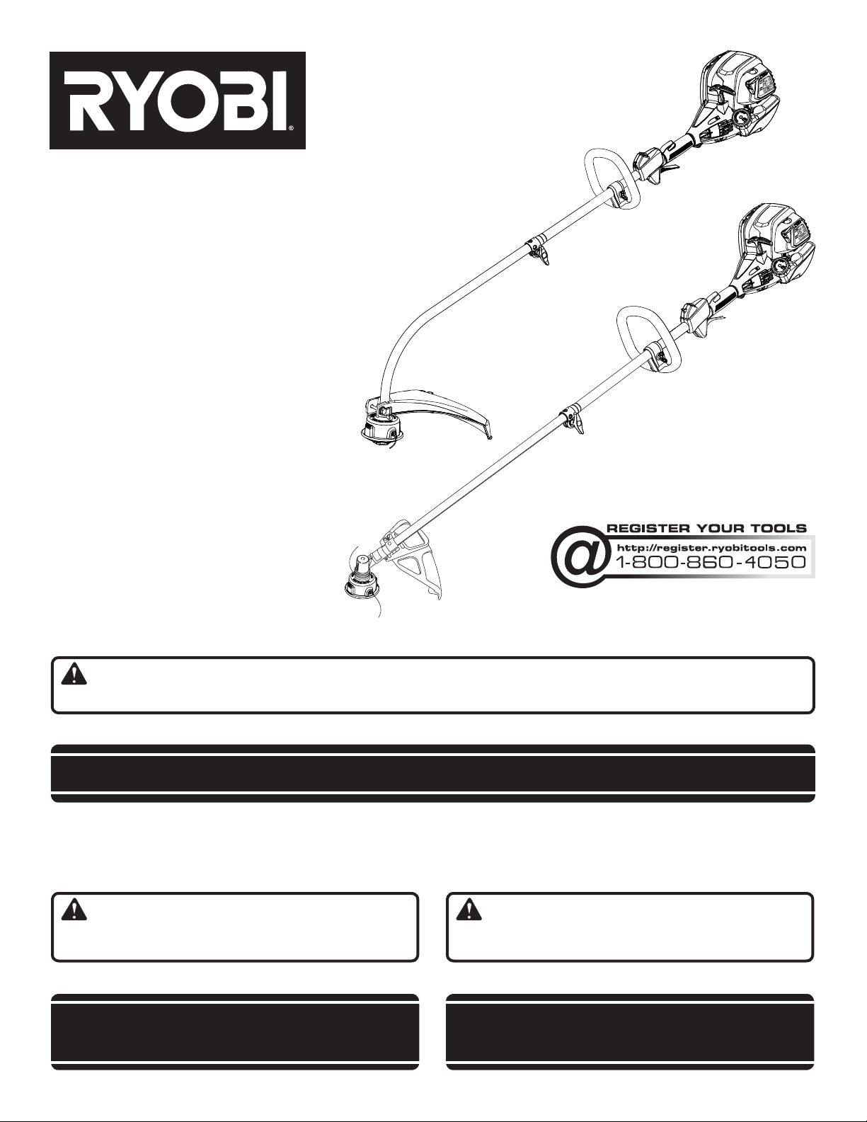
Your trimmer has been engineered and manufactured to our high standard for dependability, ease of operation, and operator safety. When properly cared for, it will give you years of rugged, trouble-free performance.
WARNING: To reduce the risk of injury, the user must read and understand the operator’s manual before using
this product.
Thank you for your purchase.
SAVE THIS MANUAL FOR FUTURE REFERENCE
Le taille-bordures à ligne a été conçue et fabriquée conformément
à nos strictes normes de fiabilité, simplicité d’emploi et sécurité
d’utilisation. Correctement entretenue, elle vous donnera des
années de fonctionnement robuste et sans problème.
AVERTISSEMENT : Pour réduire les risques de
blessures, l’utilisateur doit lire et veiller à bien comprendre le
manuel d’utilisation avant d’employer ce produit.
Merci de votre achat.
CONSERVER CE MANUEL POUR
Su recortadoras de hilo ha sido diseñada y fabricada de conformidad
con las estrictas normas para brindar fiabilidad, facilidad de uso
y seguridad para el operador. Con el debido cuidado, le brindará
muchos años de sólido y eficiente funcionamiento.
ADVERTENCIA: Para reducir el riesgo de lesiones,
el usuario debe leer y comprender el manual del operador antes
de usar este producto.
Le agradecemos su compra.
GUARDE ESTE MANUAL PARA
FUTURE RÉFÉRENCE
FUTURAS CONSULTAS
Page 2
See this fold-out section for all of the figures referenced in the operator’s manual.
Consulter l’encart à volets afin d’examiner toutes les figures mentionnées dans le manuel d’utilisation.
Consulte esta sección desplegable para ver todas las figuras a las que
se hace referencia en el manual del operador.
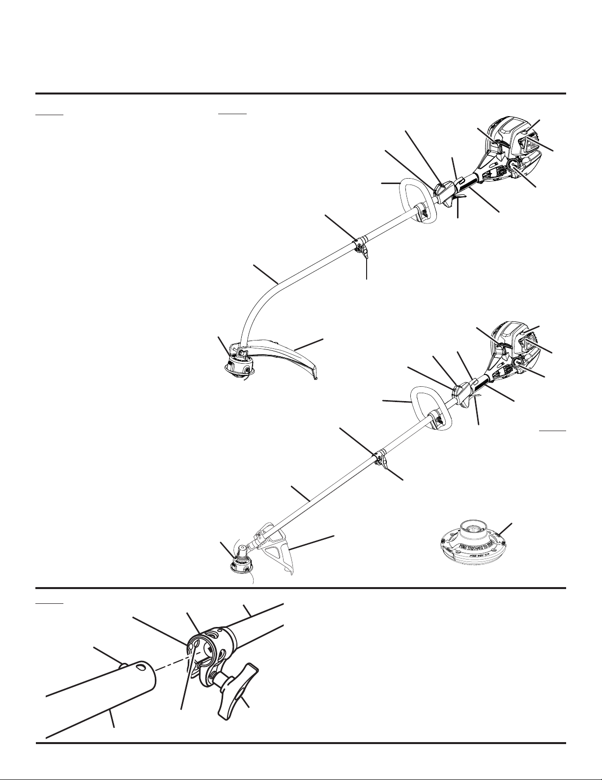
Fig. 1
A - Reel Easy string head (tête à ligne de
coupe de Reel Easy, cabezal del hilo de
Reel Easy)
B - Drive shaft housing (tube de l’arbre
moteur, alojamiento del eje de
impulsión)
C - Coupler (coupleur, acoplador)
D - Front handle (poignée avant, mango
delantero)
E - Strap hanger (dispositif d’accrochage,
colgador para la correa)
F - Ignition switch (commutateur
d’allumage, interruptor de encendido)
G - Trigger lock (verrouillage de gâchette,
seguro del gatillo)
H - Starter grip and rope (poignée et
cordon du lanceur, mango y cuerda del
arrancador)
I - Primer bulb (poire d’amorçage, bomba
de cebado)
J - Choke lever (levier de volet de départ,
palanca del anegador)
K - Fuel cap (bouchon de carburant, tapa
del tanque)
L - Rear handle (poignée arrière, mango
trasero)
M
- Throttle trigger (gâchette d’accélérateur,
gatillo del acelerador)
N - Knob (bouton, perilla)
O - Curved shaft grass deflector (déflecteur
d’herbe d’arbre courbe, deflector de
pasto del eje curvo)
P - Straight shaft grass deflector (déflecteur
d’herbe d’arbre droit, deflector de pasto
para eje recto)
Q - Pro Cut II string head (tête à ligne de
coupe de Pro Cut II, cabezal del hilo de
Pro Cut II)
C430
A
F
E
H
G
I
J
D
K
C
L
M
B
N
H
I
O
G
F
J
E
K
D
C
B
N
M
L
S430
Fig. 2
Q
A
P
D
C
B
A
A - Button (bouton, botón)
B - Guide recess (logement guide, hueco guía)
C - Coupler (coupleur, acoplador)
D - Power head shaft (tube du bloc moteur, eje de la cabezal motor)
F
E
G
E - Knob (bouton, perilla)
F - Positioning hole (trou de positionnement, orificio de posicionamiento)
G - Trimmer attachment (accessoire taille-bordures, aditamento para
recortar)
ii
Page 3
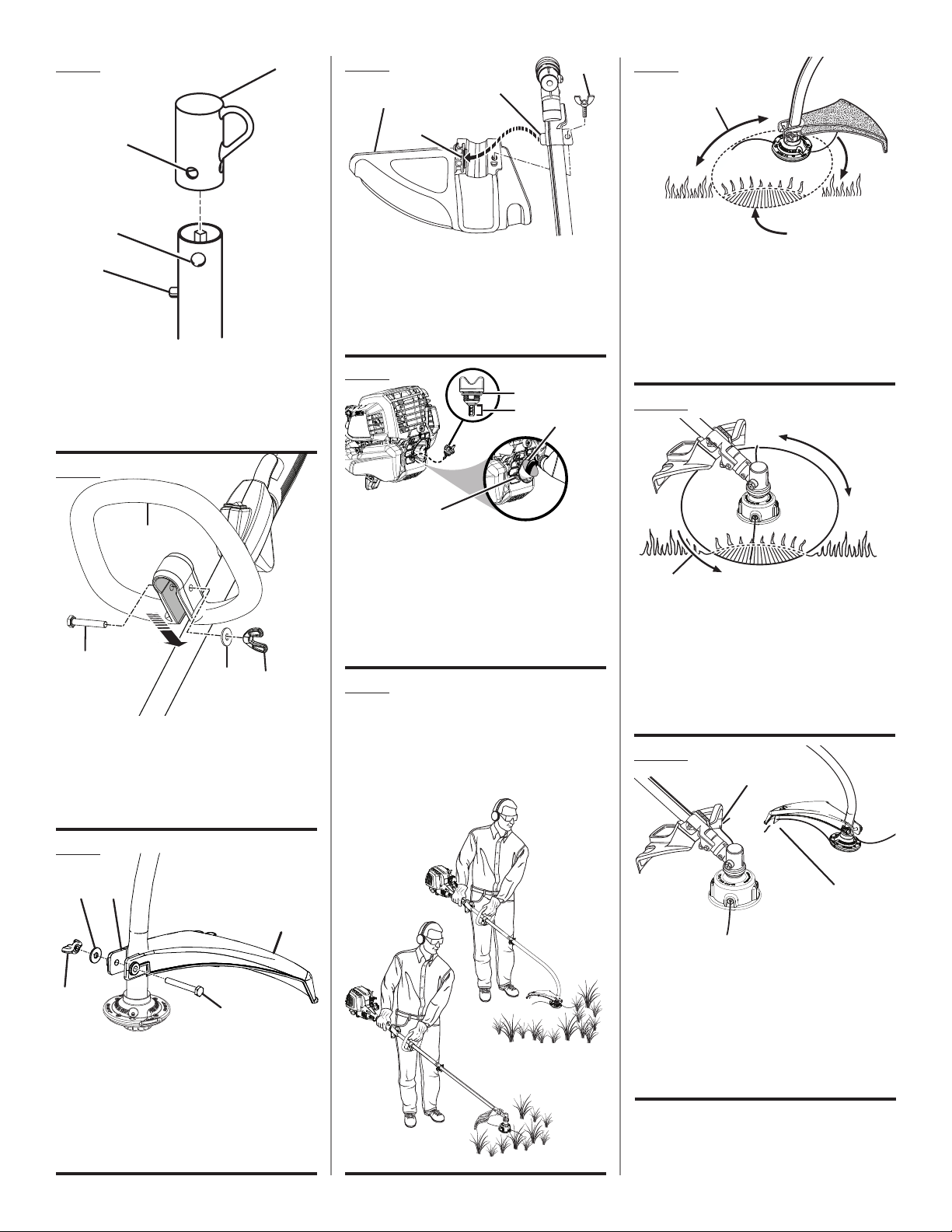
Fig. 3
A
Fig. 6
A
C
D
Fig. 9
B
A
B
C
D
A - Hanger cap (capuchon de suspension, tapa
de suspensión)
B - Hole (trou, orificio)
C - Secondary hole (trou secondaire, orificio
secundario)
D - Button (bouton, botón)
Fig. 4
A
B
C
D
A - Front handle (poignée avant, mango
delantero)
B - Bolt (boulon, perno)
C - Washer (rondelle, arandela)
D - Wing nut (écrou papillon, tuerca de
mariposa)
B
A - Straight shaft grass deflector (déflecteur
d’herbe d’arbre droit, deflector de pasto para
eje recto)
B - Slot (fente, ranura)
C - Tab (languette, orejeta)
D - Wing screw (vis à oreilles, tornillo de
mariposa)
Fig. 7
A
B
C
D
A - Oil cap/dipstick (bouchon/jauge d’huile, tapa
de relleno de aceite / varilla medidora de
aceite)
B - Hatched area (zone hachurée, área cubierta
con rayas entrecruzadas)
C - Funnel (entonnoir, embudo)
D - Oil fill hole (orifice de remplissage d’huile,
agujero de llenado de aceite)
Fig. 8
PROPER OPERATING POSITION
BONNE POSITION DE TRAVAIL
POSICIÓN CORRECTA PARA EL MANEJO DE
LA HERRAMIENTA
C
D
A - Curved shaft trimmer (taille-bordures à
arbre courbe, recortadora de eje curvo)
B - Dangerous cutting area (zone de coupe
dangereuse, área peligrosa de corte)
C - Direction of rotation (sens de rotation,
sentido de rotación)
D - Best cutting area (zone d’efficacité maximum,
mejor área de corte)
Fig. 10
A
B
C
A - Straight shaft trimmer (taille-bordures à
arbre droit, recortadora de eje recto)
B - Dangerous cutting area (zone de coupe
dangereuse, área peligrosa de corte)
C - Direction of rotation (sens de rotation,
sentido de rotación)
D - Best cutting area (zone d’efficacité maximum,
mejor área de corte)
D
Fig. 11
A
Fig. 5
C
B
D
A
A - Wing nut (écrou papillon, tuerca de
mariposa)
B - Flat washer (rondelle plate, arandela plana)
C - Bracket (support, soporte)
D - Grass deflector (déflecteur d’herbe, deflector
de pasto)
E - Hex screw (vis à six pans, tornillo de
hexagonal)
E
B
A - Straight shaft trimmer line trimming cut-
off blade (lame de sectionnement de ligne
du taille-bordures à arbre droit, cuchilla de
corte de hilo de la recortadora de eje recto)
B - Curved shaft trimmer line trimming
cut-off blade (lame de sectionnement de
ligne du taille-bordures à arbre courbe,
cuchilla de corte de hilo de la recortadora de
eje curvo)
iii
Page 4
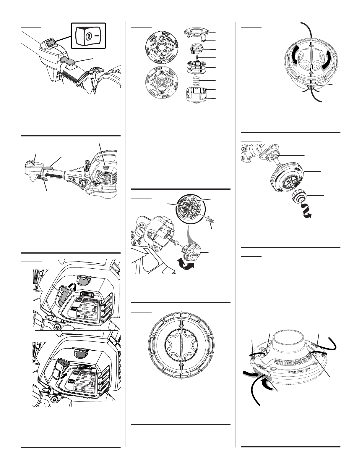
Fig. 12
A
B
C
A - Ignition switch (commutateur d’allumage,
interruptor de encendido)
B - Trigger lock (verrouillage de gâchette,
seguro del gatillo)
C - Throttle trigger (gâchette d’accélérateur,
gatillo del acelerador)
Fig. 13
C
A
B
Fig. 15
C
A
B
A - Straight shaft (arbre droit, conjunto del eje
recto)
B - Curved shaft (arbre courbe, conjunto del eje
curvo)
C - Cover (couvercle, tapadora)
D - Latches (loquets, broches)
E - Knob (bouton, perilla)
F - Hex bolt (boulon hex., perno hex.)
G - Spool (bobine, carrete)
H - Spring (ressort, resorte)
I - String head (tête de coupe, cabezal del hilo)
J - Latch opening (ouverture des loquets,
abertura para pestillos)
D
E
F
G
H
I
J
Fig. 18
INSERT LINE TO
CENTER AND
ROTATE KNOB
TO WIND
INSÉRER LE FIL
DE MANIÈRE À
CE QU’IL SOIT
CENTRÉ ET
TOURNER LE
BOUTON AFIN
DE BOBINER
LE FIL
INTRODUZCA EL HILO HASTA EL CENTRO Y
GIRE LA PERILLA PARA ENROLLARLO
A - Eyelet (oeillet, ojillo)
Fig. 19
A
B
A
D
A - Ignition switch (commutateur d’allumage,
interruptor de encendido)
B - Trigger lock (verrouillage de gâchette,
seguro del gatillo)
C - Primer bulb (poire d’amorçage, bomba
de cebado)
D - Throttle trigger (gâchette d’accélérateur,
gatillo del acelerador)
Fig. 14
A
B
C
B
Fig. 16
A
B
C
B
A - Hex-shaped opening (ouverture hexagonale,
abertura con forma hexagonal)
B - Knob (bouton, perilla)
C - Hex bolt (boulon hex., perno hex.)
Fig. 17
C
A - Drive shaft (Arbre moteur, Eje de impulsión)
B - String head (tête de coupe, cabezal del hilo)
C - Spool retainer (retenue de bobine, retén del
carrete)
Fig. 20
INSERT LINE THROUGH SLOTS UNTIL
APPROX. 1 in. PROTRUDES FROM HOLES
INSÉRER LES FILS DANS LES FENTES
DE MANIÈRE À LES FAIRE DÉPASSER
D’ENVIRON 25,4 mm (1 po)
INTRODUZCA LOS HILOS A TRAVÉS
DE LAS RANURAS HASTA QUE
SOBRESALGAN APROXIMADAMENTE
25,4 mm (1 pulg.) DE LOS ORIFICIOS
CB
A
A - Start position (position de démarrage ,
posición de arranque)
B - Start lever (palanca de arranque, levier de
volet de départ)
C - Run position (position de marche , posición
de marcha)
ALIGN LINE ON KNOB WITH ARROWS
PLACER LA LIGNE SUR LE BOUTON
VIS À VIS DES FLÈCHES
ALINEE LA LÍNEA DE LA PERILLA
CON LAS FLECHAS
iv
B
C
A - Pull line from holes to remove (tirer les fils
hors des trous afin de les retirer, tire de los
hilos para retirarlos a través de los orificios)
B - Hole (trou, agujero)
C - Slot (fente, ranura)
Page 5
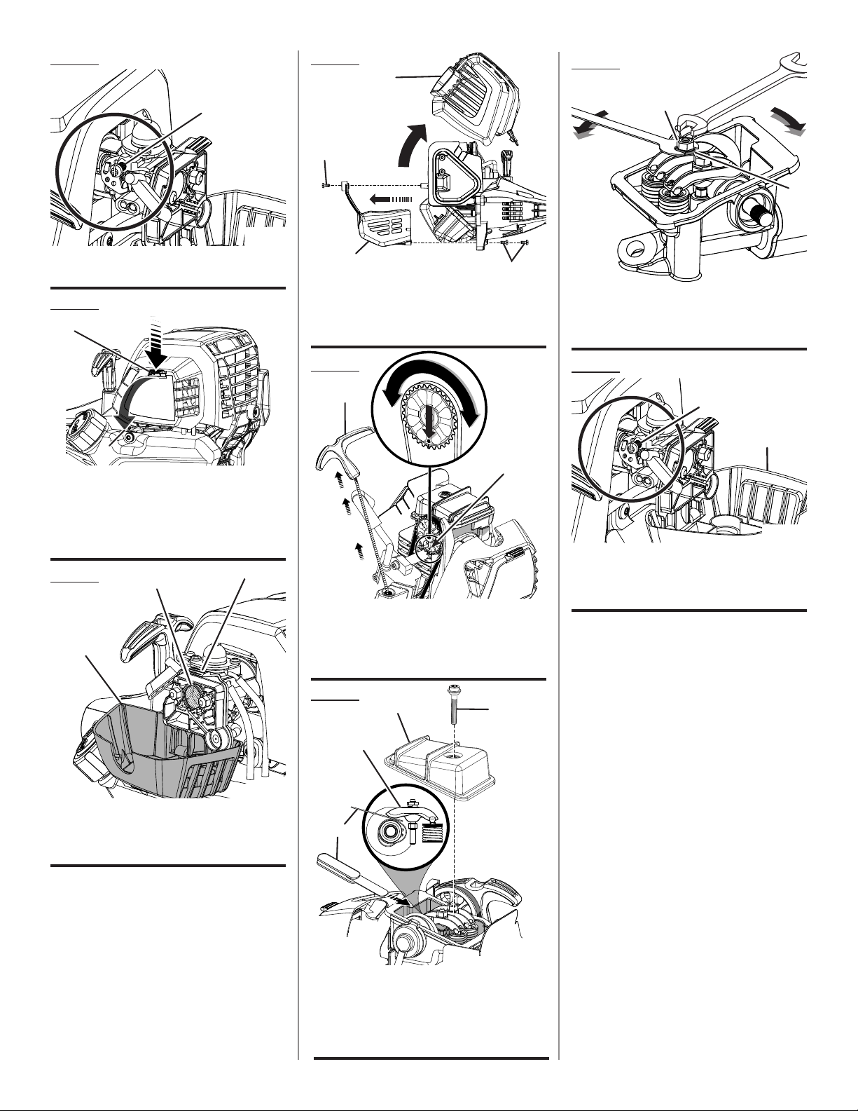
Fig. 21
Fig. 24
Fig. 27
B
A
A - Idle speed screw (vis de ralenti, tornillo de
ajuste de la velocidad en vacío)
Fig. 22
A
B
C
A - Latch (loquet, pestillo)
B - Air filter cover (couvercle du filtre à air, tapa
del filtro de aire)
C - Pull cover to open (tirer sur le couvercle
pour l’ouvrir, tire de la tapa para abrirla)
Fig. 23
A
B
C
A
C
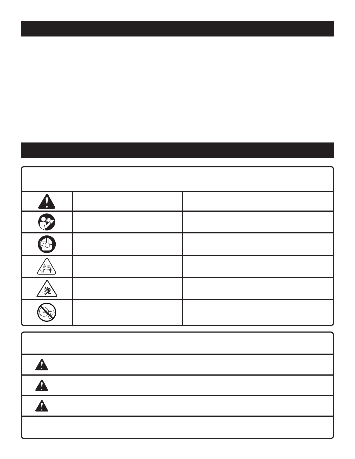
A - Screw (vis, tornillo)
B - Top engine cover (couvercle moteur
supérieur, cubierta superior del motor)
C - Bottom cover (couvercle inférieure, cubierta
inferior)
A
Fig. 25
A
B
A - Recoil starter grip (poignée du lanceur,
mango del arrancador retráctil)
B - Deep hole in belt pulley (trou profond de
la roue de courroie, orificio profundo de la
polea de la banda)
A
B
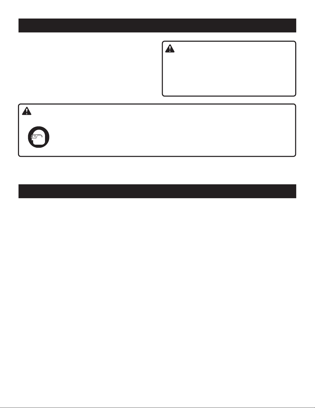
A - Retaining nut (écrou de retenue, tuerca de
retencion)
B - Adjusting nut (écrou de réglage, tuerca de
ajuste)
Fig. 28
A
B
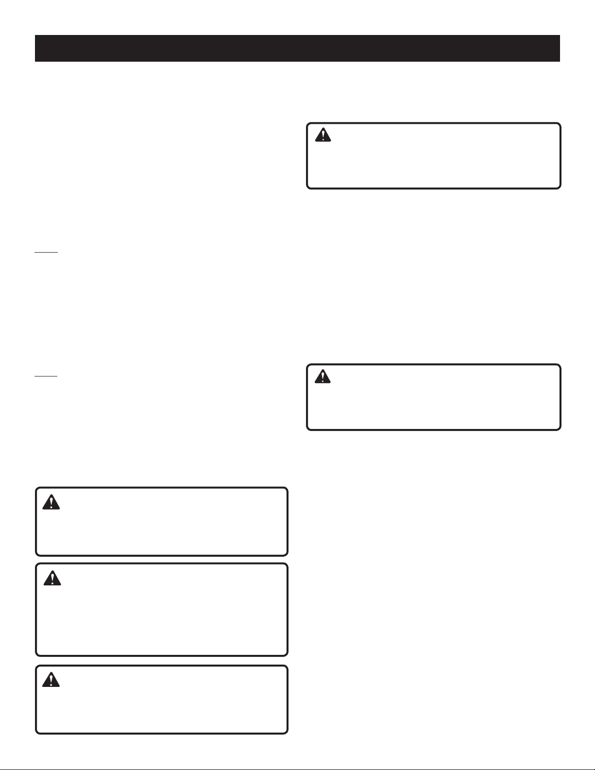
A - Idle speed screw (vis de ralenti, tornillo de
ajuste de la velocidad en vacío)
B - Air filter cover (couvercle du filtre à air, tapa
del filtro de aire)
A - Air filter cover (couvercle du filtre à air, tapa
del filtro de aire)
B - Filter screen (filtre écran, filtro pantalla)
C - Latch (loquet, pestillo)
Fig. 26
C
B
A
A - Feeler gauge (jauge d’épaisseur, calibrador
de separaciones)
B - Rocker arm (culbuteur, balancín)
C - Rocker arm cover (cache -culasse, tapa del
balancín)
D - Screw (vis, tornillo)
v
D
Page 6

TABLE OF CONTENTS
TABLE DES MATIÈRES / ÍNDICE DE CONTENIDO
Introduction ......................................................................................................................................................................2
Introduction / Introducción
General Safety Rules ........................................................................................................................................................ 3
Règles de sécurité générales / Reglas de seguridad generales
Specific Safety Rules ........................................................................................................................................................ 4
Règles de sécurité particulières / Reglas de seguridad específicas
Symbols .........................................................................................................................................................................4-5
Symboles / Símbolos
Features .........................................................................................................................................................................6-8
Caractéristiques / Características
Assembly .....................................................................................................................................................................8-10
Assemblage / Armado
Operation ...................................................................................................................................................................11-14
Utilisation / Funcionamiento
Maintenance ..............................................................................................................................................................15-18
Entretien / Mantenimiento
Troubleshooting .........................................................................................................................................................19-20
Dépannage / Solución de problemas
Warranty ....................................................................................................................................................................20-22
Garantie / Garantía
Parts Ordering and Service ...............................................................................................................................Back Page
Commande de pièces et réparation / Pedidos de piezas y servicio ......................................................... Page arrière / Pág. posterior
INTRODUCTION
INTRODUCTION / INTRODUCCIÓN
This product has many features for making its use more pleasant and enjoyable. Safety, performance, and dependability
have been given top priority in the design of this product making it easy to maintain and operate.
* * *
Ce produit offre de nombreuses fonctions destinées à rendre son utilisation plus plaisante et satisfaisante. Lors de la
conception de ce produit, l’accent a été mis sur la sécurité, les performances et la fiabilité, afin d’en faire un outil facile à
utiliser et à entretenir.
* * *
Este producto ofrece numerosas características para hacer más agradable y placentero su uso. En el diseño de este producto
se ha conferido prioridad a la seguridad, el desempeño y la fiabilidad, por lo cual se facilita su manejo y mantenimiento.
2
Page 7

GENERAL SAFETY RULES
WARNING:
Read and understand all instructions. Failure to follow all
instructions listed below may result in electric shock, fire
and/or serious personal injury.
READ ALL INSTRUCTIONS
For safe operation, read and understand all instructions
before using this product. Follow all safety instructions.
Failure to follow all safety instructions listed below, can
result in serious personal injury.
Do not allow children or untrained individuals to use this
unit.
Never start or run the engine in a closed or poorly venti-
lated area; breathing exhaust fumes can kill.
Clear the work area before each use. Remove all objects
such as rocks, broken glass, nails, wire, or string which
can be thrown or become entangled in the cutting line
or blade.
Wear safety glasses or goggles that are marked to comply
with ANSI Z87.1 standard when operating this product.
Wear heavy, long pants, boots, and gloves. Do not wear
loose fitting clothing, short pants, sandals, or go barefoot.
Do not wear jewelry of any kind.
Heavy protective clothing may increase operator fatigue,
which could lead to heat stroke. During weather that is
hot and humid, heavy work should be scheduled for early
morning or late afternoon hours when temperatures are
cooler.
Product users on United States Forest Service land, and in
some states, must comply with fire prevention regulations.
This product is equipped with a spark arrestor; however,
other user requirements may apply. Check with your
federal, state, or local authorities.
Never operate this unit on the operator’s left side.
Secure long hair above shoulder level to prevent
entanglement in moving parts.
Keep all bystanders, children, and pets at least
50 ft. away. Bystanders should be encouraged to wear
eye protection. If you are approached, stop the engine
and cutting attachment. In the case of bladed units, there
is the added risk of injury to bystanders from being struck
with the moving blade in the event of a blade thrust or
other unexpected reaction of the saw.
Do not operate this unit when you are tired, ill, or under
the influence of alcohol, drugs, or medication.
Do not operate in poor lighting.
Keep firm footing and balance. Do not overreach.
Overreaching can result in loss of balance or exposure
to hot surfaces.
Keep all parts of your body away from any moving
part.
To avoid hot surfaces, never operate the unit with the
bottom of the engine above waist level.
Do not touch area around the muffler or cylinder of the
unit, these parts get hot from operation.
Always stop the engine and remove the spark plug wire
before making any adjustments or repairs except for
carburetor adjustments.
Inspect the unit before each use for loose fasteners, fuel
leaks, etc. Replace any damaged parts before use.
The cutting attachment should never rotate at idle during
normal use. The cutting attachment may rotate at idle
during carburetor adjustments.
It has been reported that vibrations from hand-held tools
may contribute to a condition called Raynaud’s Syndrome
in certain individuals. Symptoms may include tingling,
numbness, and blanching of the fingers, usually apparent
upon exposure to cold. Hereditary factors, exposure to
cold and dampness, diet, smoking, and work practices
are all thought to contribute to the development of these
symptoms. It is presently unknown what, if any, vibrations
or extent of exposure may contribute to the condition.
There are measures that can be taken by the operator to
possibly reduce the effects of vibration:
a) Keep your body warm in cold weather. When oper-
ating the unit wear gloves to keep hands and wrists
warm. It is reported that cold weather is a major factor
contributing to Raynaud’s Syndrome.
b) After each period of operation, exercise to increase
blood circulation.
c) Take frequent work breaks. Limit the amount of
exposure per day.
d) Keep the tool well maintained, fasteners tightened,
and worn parts replaced.
If you experience any of the symptoms of this condition,
immediately discontinue use and see your physician about
these symptoms.
Store fuel in a container approved for gasoline.
Wipe up any fuel spillage. Move 30 ft. away from refueling
site before starting engine. Slowly remove the fuel cap
after stopping engine. Do not smoke when refueling.
Stop the engine and allow to cool before refueling or
storing the unit.
Allow the engine to cool; empty the fuel tank and secure
the unit from moving before transporting in a vehicle.
Wear your protective equipment and observe all safety
instructions. For units equipped with a clutch, be sure
the cutting attachment stops turning when the engine
idles. When the unit is turned off make sure the cutting
attachment has stopped before the unit is set down.
3 — English
Page 8
SPECIFIC SAFETY RULES
Inspect before use. Replace damaged parts. Make sure
fasteners are in place and secure. Check for fuel leaks.
Replace string head if cracked, chipped, or damaged in any
way. Be sure the string head or blade is properly installed and
securely fastened. Failure to do so can cause serious injury.
Make sure all guards, straps, deflectors, and handles are
properly and securely attached.
Use only the manufacturer’s replacement line in the cutting
head. Do not use any other cutting attachment. To install
any other brand of replacement line or cutting head to this
string trimmer can result in serious personal injury. Never
use, for example, wire or wire-rope, which can break off and
become a dangerous projectile.
Never operate unit without the grass deflector in place and
in good condition.
Maintain a firm grip on both handles while trimming. Keep
string head below waist level. Never cut with the string head
located over 30 in. or more above the ground.
This product is intended for infrequent use by homeowners
and other occasional users for such general applications as
trimming light and heavy vegetation, etc. It is not intended
for prolonged use. Prolonged periods of operation can cause
circulatory problems in the user’s hands due to vibration.
For such use, it may be appropriate to use a saw having an
anti-vibration feature.
SYMBOLS
Some of the following symbols may be used on this product. Please study them and learn their meaning for safe
operation of this product.
SYMBOL NAME EXPLANATION
Safety Alert Precautions that involve your safety.
Read the Operator’s Manual
Wear Eye and Hearing Protection
Keep Bystanders Away Keep all bystanders at least 50 ft. away.
Ricochet
No Blade
The following signal words and meanings are intended to explain the levels of risk associated with this product.
SYMBOL SIGNAL MEANING
DANGER:
WARNING:
Indicates an imminently hazardous situation, which, if not avoided, will result
in death or serious injury.
Indicates a potentially hazardous situation, which, if not avoided, could result
in death or serious injury.
To reduce the risk of injury, user must read and understand operator’s manual before using this product.
Wear eye protection which is marked to comply
with ANSI Z87.1 as well as hearing protection when
operating this equipment.
Thrown objects can ricochet and result in personal injury
or property damage.
Do not install or use any type of blade on a product displaying this symbol.
CAUTION:
CAUTION:
Indicates a potentially hazardous situation, which, if not avoided, may result in
minor or moderate injury.
(Without Safety Alert Symbol) Indicates a situation that may result in property
damage.
4 — English
Page 9
SYMBOLS
SERVICE
Servicing requires extreme care and knowledge and should
be performed only by a qualified service technician. For
service we suggest you return the product to your nearest
AUTHORIZED SERVICE CENTER for repair. When servicing, use only identical replacement parts.
WARNING:
The operation of any power tool can result in foreign objects being thrown into your eyes, which can
result in severe eye damage. Before beginning power tool operation, always wear safety goggles or
safety glasses with side shields and, when needed, a full face shield. We recommend Wide Vision Safety
Mask for use over eyeglasses or standard safety glasses with side shields. Always use eye protection
which is marked to comply with ANSI Z87.1.
SAVE THESE INSTRUCTIONS
WARNING:
To avoid serious personal injury, do not attempt to use this
product until you read thoroughly and understand completely the operator’s manual. If you do not understand
the warnings and instructions in the operator’s manual,
do not use this product. Call Ryobi customer service for
assistance.
FEATURES
PRODUCT SPECIFICATIONS
Weight - (without fuel)
C430 ..................................................................................................................................................................10.7 lbs.
S430 ...................................................................................................................................................................11.8 lbs.
Line cutting width
C430 .......................................................................................................................................................................17 in.
S430 ........................................................................................................................................................................18 in.
Engine displacement .................................................................................................................................................30cc
Engine Lubricant Volume ............................................................................................................................................75 ml
Line diameter
Reel Easy String Head ........................................................................................................................................ .095 in.
Pro Cut II String Head ............................................................................................................... .095 in. to .105 in. max.
KNOW YOUR STRING TRIMMER
See Figure 1.
The safe use of this product requires an understanding of
the information on the tool and in this operator’s manual as
well as a knowledge of the project you are attempting. Before
use of this product, familiarize yourself with all operating
features and safety rules.
GRASS DEFLECTOR
The trimmer includes a grass deflector that helps protect
you from flying debris.
OIL CAP/DIPSTICK
Remove the oil fill cap to check and add lubricant when
necessary.
ERGONOMIC DESIGN
The design of the trimmer provides for easy handling. It is
designed for comfort and ease of grasp when operating in
different positions and at different angles.
5 — English
TOP-MOUNTED MOTOR
The top-mounted motor improves balance and is located
away from the dust and debris of the cutting area.
Page 10
ASSEMBLY
UNPACKING
This product requires assembly.
Carefully remove the product and any accessories from
the box. Make sure that all items listed in the packing list
are included.
Inspect the product carefully to make sure no breakage
or damage occurred during shipping.
Do not discard the packing material until you have care-
fully inspected and satisfactorily operated the product.
If any parts are damaged or missing, please call
1-800-860-4050 for assistance.
PACKING LIST
C430
Trimmer Assembly
Pro Cut II String Head
Spool Retainer
Front Handle
Curved Shaft Grass Deflector
Bottle of 4-Cycle Lubricant
Oil Fill Funnel
Hanger Cap
Operator’s Manual
INSTALLING THE POWER HEAD TO THE
ATTACHMENT
See Figure 2.
WARNING:
Never install, remove, or adjust any attachment while
power head is running. Failure to stop the engine can
cause serious personal injury.
The attachment connects to the power head by means of
a coupler device.
Loosen the knob on the coupler of the power head shaft
and remove the end cap from the attachment.
Push in the button located on the attachment shaft. Align
the button with the guide recess on the power head coupler
and slide the two shafts together. Rotate the attachment
shaft until the button locks into the positioning hole.
NOTE: If the button does not release completely in the
positioning hole, the shafts are not locked into place.
Slightly rotate from side to side until the button is locked
into place.
Tighten the knob securely.
S430
Trimmer Assembly
Pro Cut II String Head
Spool Retainer
Front Handle
Straight Shaft Grass Deflector
Bottle of 4-Cycle Lubricant
Oil Fill Funnel
Hanger Cap
Operator’s Manual
WARNING:
If any parts are damaged or missing do not operate this
product until the parts are replaced. Failure to heed this
warning could result in serious personal injury.
WARNING:
Do not attempt to modify this product or create accessories not recommended for use with this product. Any
such alteration or modification is misuse and could result
in a hazardous condition leading to possible serious
personal injury.
WARNING:
To prevent accidental starting that could cause serious
personal injury, always disconnect the engine spark plug
wire from the spark plug when assembling parts.
WARNING:
Be certain the knob is fully tightened before operating
equipment; check it periodically for tightness during use
to avoid serious personal injury.
REMOVING THE ATTACHMENT FROM THE
POWER HEAD
For removing or changing the attachment:
Loosen the knob.
Push in the button and twist the shafts to remove and
separate ends.
ATTACHING THE STORAGE HANGER
See Figure 3.
There are two ways to hang your attachment for storage.
To use the hanger cap, push in the button and place the
hanger cap over end of the lower end attachment shaft.
Slightly rotate the cap from side to side until the button
locks into place.
The secondary hole in the attachment shaft can be used
for hanging purposes as well.
ATTACHING THE FRONT HANDLE
See Figure 4.
Remove wing nut, washer, and bolt from the front
handle.
Install the front handle onto the top side of the drive shaft
housing in the area indicated by the label.
6 — English
Page 11
ASSEMBLY
NOTE: The open side of the handle should face the
operator.
Place the bolt through the front handle.
NOTE: The hex bolt head fits inside the hex recess molded
into one side of the handle.
Reinstall the washer and wing nut.
Tighten wing nut securely.
ATTACHING THE GRASS DEFLECTOR
WARNING:
The line cutting blade on the grass deflector is sharp.
Avoid contact with the blade. Failure to avoid contact
can result in serious personal injury.
TO ATTACH THE CURVED SHAFT GRASS
DEFLECTOR — C430
See Figure 5.
Remove hex screw, flat washer, and wing nut from grass
deflector.
Press the grass deflector onto the bottom of the curved
shaft as shown.
Insert the hex screw through the grass deflector and the
bracket on the curved shaft.
Place the flat washer on the hex screw.
Place the wing nut on the hex screw and tighten
securely.
TO ATTACH THE STRAIGHT SHAFT GRASS
DEFLECTOR — S430
See Figure 6.
Remove the wing screw from the grass deflector.
Insert the tab on the mounting bracket in the slot on the
grass deflector.
Align the screw hole in the mounting bracket with the
screw hole in the grass deflector.
Insert the wing screw through the mounting bracket and
into the grass deflector.
Tighten the screw securely.
OPERATION
WARNING:
Do not allow familiarity with this product to make you
careless. Remember that a careless fraction of a second is
sufficient to inflict serious injury.
WARNING:
Always wear safety goggles or safety glasses with side
shields when operating power tools. Failure to do so
could result in objects being thrown into your eyes resulting in possible serious injury.
WARNING:
Do not use any attachments or accessories not recommended by the manufacturer of this product. The use of
attachments or accessories not recommended can result
in serious personal injury.
FUELING AND REFUELING THE TRIMMER
C lean s urfac e arou nd fue l cap t o prev ent
contamination.
Loosen fuel cap slowly. Rest the cap on a clean
surface.
Carefully pour fuel into the tank. Avoid spillage.
7 — English
Prior to replacing the fuel cap, clean and inspect the
gasket.
Immediately replace fuel cap and hand tighten. Wipe up
any fuel spillage.
NOTE: It is normal for smoke to be emitted from a new
engine after first use.
WARNING:
Always shut off engine before fueling. Never add fuel to
a machine with a running or hot engine. Move at least
30 ft. from refueling site before starting engine. Do not
smoke! Failure to heed this warning could result in serious personal injury.
OXYGENATED FUELS
Some conventional gasolines are blended with alcohol or an
ether compound. These gasolines are collectively referred
to as oxygenated fuels. To meet clean air standards, some
areas of the United States and Canada use oxygenated fuels
to help reduce emissions.
If using an oxygenated fuel, make sure it is unleaded and
meets the minimum octane rating requirements. Before using
an oxygenated fuel, try to confirm the fuel’s contents. Some
states/provinces require this information to be posted on the
pump. The following are the EPA approved percentages of
oxygenates:
Page 12
OPERATION
Ethanol (ethyl or grain alcohol) 10% by volume. You
may use gasoline containing up to 10% ethanol by volume.
Gasoline containing ethanol may be marketed under the
name “Gasohol.” Do not use E85 fuel.
MTBE (methyl tertiary butyl ether) 15% by volume. You
may use gasoline containing up to 15% MTBE by volume.
Methanol (methyl or wood alcohol) 5% by volume. You
may use gasoline containing up to 5% methanol by volume
as long as it also contains cosolvents and corrosion inhibitors to protect the fuel system. Gasoline containing more
than 5% methanol by volume may cause starting and/or
performance problems. It may also damage metal, rubber,
and plastic parts of the product or your fuel system.
If you notice any undesirable operating symptoms, try another service station or switch to another brand of gasoline.
NOTE: Fuel system damage or performance problems resulting from the use of an oxygenated fuel containing more
than the percentages of oxygenates stated previously are
not covered under warranty.
CAUTION:
Do not overfill. Overfilling the crankcase may cause
excessive smoke and engine damage.
OPERATING THE TRIMMER
See Figure 8.
WARNING:
Always position the unit on the operator’s right side. The
use of the unit on the operator’s left side will expose
the user to hot surfaces and can result in possible burn
injury.
WARNING:
To avoid burns from hot surfaces, never operate unit with
the bottom of the engine above waist level.
CAUTION:
Attempting to start the engine before it has been properly
filled with lubricant will result in equipment failure.
ADDING/CHECKING ENGINE LUBRICANT
See Figure 7.
Engine lubricant has a major influence on engine performance and service life. For general, all-temperature use,
SAE 10W-30 is recommended. Always use a 4-stroke motor lubricant that meets or exceeds the requirements for
API service classification SJ. Check lubricant level before
each use.
NOTE: Non-detergent or 2-stroke engine lubricants will
damage the engine and should not be used.
To add engine lubricant:
Remove the cap and seal from lubricant bottle pro-
vided.
Unscrew the oil cap/dipstick and remove.
Using funnel provided, add entire bottle of engine lubricant
through oil fill hole.
Reinstall the oil cap/dipstick and secure.
To check engine lubricant level:
Set engine on a flat surface.
Wipe dipstick clean and re-seat in hole; do not rethread.
Remove dipstick again and check lubricant level. Lubricant
level should fall within the hatched area on the dipstick.
If level is low, add engine lubricant until the fluid level rises
to the upper portion of the hatched area on the dipstick.
Replace and secure the oil cap/dipstick.
Hold the trimmer with your right hand on the rear handle
and your left hand on the front handle. Keep a firm grip with
both hands while in operation. Trimmer should be held at a
comfortable position with the rear handle about hip height.
Cut tall grass from the top down. This will prevent grass from
wrapping around the shaft housing and string head which
could cause damage from overheating. If grass becomes
wrapped around the string head, STOP THE ENGINE, disconnect the spark plug wire, and remove the grass.
WARNING:
Always hold the string trimmer away from the body keeping clearance between the body and the product. Any
contact with the housing or string trimmer cutting head can
result in burns and/or other serious personal injury.
TO ADVANCE THE CUTTING LINE (REEL EASY
STRING HEAD)
Line advance is controlled by tapping the string head on
grass while running engine at full throttle.
Run engine at full throttle.
Tap the knob on ground to advance line. The line advances
each time the knob is tapped. Do not hold the knob on
the ground.
NOTE: The line trimming cut-off blade on the grass deflector
will cut the line to the correct length.
NOTE: If the line is worn too short you may not be able to
advance the line by tapping it on the ground. If so, stop the
engine and manually advance the line.
8 — English
Page 13

OPERATION
To advance the cutting line manually:
Stop the engine and disconnect the spark plug wire.
Push the knob in while pulling on line(s) to manually
advance the line.
NOTE: Pro Cut II line cannot be advanced. To replace the
line, refer to Installing Line in Pro Cut II String Head later
in this manual.
CUTTING TIPS
See Figures 9 -10.
Avoid hot surfaces by always keeping the tool away from
your body. (Proper operating position shown in figure 8.)
Keep the trimmer tilted toward the area being cut; this is
the best cutting area.
The curved shaft trimmer cuts when passing the unit from
right to left. The straight shaft trimmer cuts when passing
the unit from left to right. This will avoid throwing debris at
the operator. Avoid cutting in the dangerous area shown
in illustration.
Use the tip of line to do the cutting; do not force string
head into uncut grass.
Wire and picket fences cause extra line wear, even
breakage. Stone and brick walls, curbs, and wood may
wear line rapidly.
Avoid trees and shrubs. Tree bark, wood moldings, siding,
and fence posts can easily be damaged by the line.
GRASS DEFLECTOR LINE TRIMMING CUT-OFF
BLADE
See Figure 11.
The trimmer is equipped with a line trimming cut-off blade
on the grass deflector. For best cutting, advance line until it
is trimmed to length by the cut-off blade. Advance the line
whenever you hear the engine running faster than normal,
or when trimming efficiency diminishes. This will maintain
best performance and keep the line long enough to advance
properly.
STARTING AND STOPPING
See Figures 12 - 14.
To start a cold engine:
DO NOT squeeze the throttle trigger until the engine starts
and runs.
Lay the trimmer on a flat, bare surface.
PRIME - Press the primer bulb 7 times.
SET the start lever to the START position.
PULL the rope until the engine starts.
Wait 6-10 seconds, then squeeze the trigger to run.
NOTE: Squeezing and releasing the throttle trigger releases
the start lever to the RUN position.
To start a warm engine:
PULL the rope until the engine starts.
To stop the engine:
Press and hold the switch in the stop “ ” position until
the engine stops.
9 — English
Page 14
MAINTENANCE
WARNING:
When servicing, use only identical replacement parts.
Use of any other parts may create a hazard or cause
product damage.
WARNING:
Always wear safety goggles or safety glasses with side
shields during tool operation. If operation is dusty, also
wear a dust mask.
WARNING:
Before inspecting, cleaning, or servicing the machine,
shut off engine, wait for all moving parts to stop, and
disconnect spark plug wire and move it away from spark
plug. Failure to follow these instructions can result in
serious personal injury or property damage.
GENERAL MAINTENANCE
Avoid using solvents when cleaning plastic parts. Most
plastics are susceptible to damage from various types of
commercial solvents and may be damaged by their use. Use
clean cloths to remove dirt, dust, lubricant, grease, etc.
WARNING:
Do not at any time let brake fluids, gasoline, petroleumbased products, penetrating lubricants, etc., come in contact with plastic parts. Chemicals can damage, weaken or
destroy plastic which may result in serious personal
injury.
You can often make adjustments and repairs described here.
For other repairs, have the trimmer serviced by an authorized
service dealer.
NOTE: Only use the knob to tighten the bolt. The use of
other tools may allow overtightening of the bolt, which
could damage the string head.
If removed, replace the spring into the string head and
push down to seat.
Reinstall the spool. For the C430, the spool should be
placed so “This side out for curved shaft” is visible. For
the S430, the spool should be placed so “This side out
for straight shaft” is visible.
Replace the knob in the spool.
Replace the string head cover, aligning latches with
openings in the string head. Press cover and string head
together until both latches snap into openings securely.
Install line as described in the next section of this
manual.
INSTALLING LINE IN REEL EASY STRING
HEAD
See Figures 17 - 18.
Use .095 in. diameter monofilament line.
Stop the engine and disconnect the spark plug wire.
Cut one piece of line approximately 25 ft. in length.
Rotate knob on string head until line on knob aligns with
arrows on top of string head.
Insert one end of line into eyelet located on the side of
the string head and push until line comes out through
eyelet on the other side. Continue to push line through
the string head until the middle section of the line is inside
the string head and line outside the string head is evenly
divided on each side.
Rotate the knob on the string head to wind the line.
If using the C430, knob should be rotated counterclockwise. If using the S430, knob should be rotated clockwise. Wind the line until approximately
8 in. remains protruding from the string head.
INSTALLING REEL EASY STRING HEAD
See Figures 15 - 16.
Stop the engine and disconnect the spark plug wire.
Remove currently installed string head.
Open the Reel Easy string head by depressing the latches
on each side. The contents of the string head are spring
loaded, so keep your other hand over the string head
cover while depressing the latches.
Remove the string head cover, knob, and spool and set
aside.
Place the string head on the drive shaft. Make sure the
string head is fully seated.
Install the hex bolt into the opening on the drive shaft
and secure using the hex-shaped opening in the knob
to tighten.
10 — English
INSTALLING PRO CUT II STRING HEAD
See Figure 19.
Stop the engine and disconnect the spark plug wire.
Remove currently installed string head.
Install the string head on the drive shaft until fully
seated.
Install the spool retainer and turn counterclockwise for
C430 or clockwise for S430 to secure.
Install line as described in the next section of this
manual.
INSTALLING LINE IN PRO CUT II STRING
HEAD
See Figure 20.
Use monofilament line between .095 in. and .105 in. diameter. Use quality monofilament replacement line for best
performance.
Page 15
MAINTENANCE
Stop the engine and disconnect the spark plug wire.
Gather two of the pre-cut lengths of trimmer line provided
or cut two pieces of trimmer line, in 11 in. lengths.
Insert the lines into the slots located on the sides of the
string head. Line should be pushed in until approximately
1 in. protrudes from the holes on the top of the string
head.
Remove old line by pulling it from the holes located on
the top of the string head.
CLEANING THE EXHAUST PORT AND
MUFFLER
NOTE: Depending on the type of fuel used, the type and
amount of lubricant used, and/or your operating conditions, the
exhaust port, muffler, and/or spark arrestor screen may become blocked with carbon deposits. If you notice a power
loss with your gas powered tool, you may need to remove
these deposits to restore performance. We highly recommend that only qualified service technicians perform this
service.
SPARK ARRESTOR
The spark arrestor must be replaced every 50 hours or yearly
to ensure proper performance of your product. Spark arrestors may be in different locations depending on the model
purchased. Please contact your nearest service dealer for
the location of the spark arrestor for your model.
IDLE SPEED ADJUSTMENT
See Figure 21.
If the cutting attachment turns at idle, the idle speed screw
needs adjusting on the engine. Turn the idle speed screw
counterclockwise to reduce the idle RPM and stop the cutting attachment movement. If the cutting attachment still
moves at idle speed, contact a service dealer for adjustment
and discontinue use until the repair is made.
WARNING:
The cutting attachment should never turn at idle. Turn
the idle speed screw counterclockwise to reduce the
idle RPM and stop the cutting attachment, or contact a
service dealer for adjustment and discontinue use until
the repair is made. Serious personal injury may result
from the cutting attachment turning at idle.
CLEANING AIR FILTER SCREEN
See Figures 22 - 23.
For proper performance and long life, keep air filter screen
clean.
Remove the air filter cover by pushing down on the latch
with your thumb while gently pulling on the cover.
Brush the air filter screen lightly to clean.
Replace the air filter cover by inserting the tabs on the
bottom of the cover into the slots on the air filter base;
push the cover up until it latches securely in place.
FUEL CAP
WARNING:
A leaking fuel cap is a fire hazard and must be replaced
immediately.
The fuel cap contains a non-serviceable filter and a check
valve. A clogged fuel filter will cause poor engine performance. If performance improves when the fuel cap is loosened, check valve may be faulty or filter clogged. Replace
fuel cap if required.
SPARK PLUG REPLACEMENT
This engine uses an NGK CMR7A or Champion RZ7C spark
plug with .025 in. electrode gap. Use an exact replacement
and replace annually.
CHANGING ENGINE LUBRICANT
See Figure 24.
For best performance, engine lubricant should be changed
after every 25 hours of operation.
To change the engine lubricant:
Stop the engine and disconnect the spark plug wire. Allow
the engine to cool completely before proceeding.
Remove the screw from the top engine cover and set
aside.
Remove the screws from the bottom of the engine cover.
Remove the bottom cover and set aside.
Remove the oil fill cap/dipstick.
Tip powerhead on its side and allow lubricant to drain
from the oil fill hole into an approved container.
NOTE: Drain the lubricant while the engine is still warm
but not hot. Warm lubricant will drain quickly and more
completely.
Return the power head to an upright position and refill
with lubricant following the instructions in the Adding/
Checking Engine Lubricant section previously in this
manual.
Reinstall the bottom engine cover. Replace the screws
and tighten securely.
Replace the screw in the top engine cover and tighten
securely.
NOTE: Used lubricant should be disposed of at an approved
disposal site. See your local retailer for more information.
11 — English
Page 16

MAINTENANCE
ADJUSTING VALVE-TO-ROCKER ARM
CLEARANCE
See Figures 25 - 27.
Inspect the valve-to-rocker arm clearance after every
25 hours of operation. This should be done in a clean, dustfree environment.
NOTE: This procedure requires partial disassembly of the
engine. If you are unsure if you are qualified to perform this
operation, take the unit to an authorized service center.
Stop the engine and disconnect the spark plug wire. Allow
the engine to cool completely before proceeding.
Remove the screw from the top engine cover. Remove
engine cover and set aside.
Using a Torx screwdriver, remove the screw from the
rocker arm cover. Remove the cover and set aside.
Align rocker arms by pulling the recoil starter grip just until
the deep hole in the belt pulley is located at the bottom
as shown in figure 24.
Place the feeler gauge under each rocker arm and mea-
sure the gap as shown in figure 25. The gap should be
between .0045 in. and .005 in. for both rocker arms.
NOTE: Use a standard automotive .005 in. feeler gauge.
The feeler gauge should slide between the rocker arm
and valve stem with a slight amount of resistance but
without binding.
If the valve clearance is not .005 in., the clearance should
be adjusted as follows:
While holding a wrench on the flats of the adjusting nut
with one hand, loosen the retaining nut with a second
wrench as shown in figure 26.
Rotate the adjusting nut until it touches the feeler gauge.
Once the gap setting is correct, hold the wrench on
the flats of the adjusting nut and retighten the retaining
nut securely.
Adjust the second rocker arm, if necessary.
Replace the rocker arm cover and screw; tighten
securely.
Replace the top engine cover and screw; tighten
securely.
WARNING:
Ensure all engine cover and all engine parts are completely
and properly reassembled before starting engine. Failure
to correctly reassemble engine may result in serious injury
or property damage.
STORING THE PRODUCT
Clean all foreign material from the product. Store idle unit
indoors in a dry, well-ventilated area that is inaccessible
to children. Keep away from corrosive agents such as
garden chemicals and de-icing salts.
Abide by all ISO and local regulations for the safe storage
and handling of gasoline.
When storing 1 month or longer:
Drain all fuel from tank into a container approved for
gasoline. Run engine until it stops.
12 — English
Page 17

TROUBLESHOOTING
IF THESE SOLUTIONS DO NOT SOLVE THE PROBLEM CONTACT YOUR AUTHORIZED SERVICE DEALER.
PROBLEM POSSIBLE CAUSE SOLUTION
Engine will not start
Engine does not reach full speed and
emits excessive smoke
No spark.
No fuel.
Engine is flooded.
Air filter screen is dirty.
Spark arrestor screen is dirty.
Spark plug fouled.
Clean or replace spark plug. Reset
spark plug gap. Refer to Spark Plug
Replacement earlier in this manual.
Push primer bulb until bulb is full of fuel.
If bulb does not fill, primary fuel delivery
system is blocked. Contact a service
dealer. If primer bulb fills, engine may
be flooded, proceed to next item.
Set the start lever to the START position.
Squeeze the trigger and pull the rope
repeatedly until the engine starts and
runs.
NOTE: Depending on the severity of
the flooding, this may require numerous
pulls of the rope.
Clean air filter screen. Refer to Clean-
ing Air Filter Screen earlier in this
manual.
Contact a servicing dealer.
Clean or replace spark plug. Reset
spark plug gap. Refer to Spark Plug
Replacement earlier in this manual.
Engine starts, runs, and accelerates
but will not idle
Line will not advance Line is welded to itself.
Spool retainer hard to turn Screw threads are dirty or damaged. Clean threads and lubricate with grease
Grass wraps around driveshaft housing
and string head
Idle speed screw on carburetor needs
adjustment.
Not enough line on spool.
Line is worn too short.
Line is tangled on spool.
Engine speed is too slow.
Cutting tall grass at ground level.
Operating trimmer at part throttle.
Turn idle speed screw clockwise to
increase idle speed. See Figure 28.
Replace line. Refer to the applicable line
replacement section in this manual.
Install more line. Refer to the applicable line replacement section in this
manual.
Pull lines while alternately pressing
down on and releasing spool retainer.
Remove line from spool and rewind.
Refer to the applicable line replacement
section in this manual.
Advance line at full throttle.
- if no improvement, replace the spool
retainer.
Cut tall grass from the top down to
prevent wrapping.
Operate trimmer at full throttle.
13 — English
Page 18

TROUBLESHOOTING
CALL
1-800-860-4050
IF THESE SOLUTIONS DO NOT SOLVE THE PROBLEM CONTACT YOUR AUTHORIZED SERVICE DEALER.
PROBLEM POSSIBLE CAUSE SOLUTION
Engine emits too much smoke Too much oil in crankcase. Drain lubricant and refill with correct
amount of 10W-30 engine lubricant.
See Adding/Ch e c king Engine
Lubricant in the Operation section of
this manual.
WARRANTY
EMISSIONS MAINTENANCE SCHEDULE AND WARRANTED PARTS LIST
Emissions Parts Inspect Before Clean Every Replace Every Replace Every
Each Use 5 Hours 25 Hours or Yearly 50 Hours or Yearly
AIR FILTER ASSY
INCLUDES:
FILTER ................................................................................ X
ENGINE LUBRICANT .................. X .....................................................................................X
SPARK SCREEN ................................................................................................................................................................X
CARBURETOR ASSY
INCLUDES:
HEAT DAM ............................... X
GASKETS ................................. X
FUEL TANK ASSY
INCLUDES:
FUEL LINES ............................. X
FUEL CAP ................................ X
FUEL FILTER ............................ X
IGNITION ASSY
INCLUDES:
SPARK PLUG .................................................................................................................................................................X
ALL EMISSIONS-RELATED PARTS ARE WARRANTED FOR TWO YEARS, OR FOR THE PERIOD OF TIME PRIOR TO THE PARTS’ FIRST
SCHEDULED REPLACEMENT, WHICHEVER COMES FIRST.
MAKE THE MOST OF YOUR PURCHASE!
Go to http://register.ryobitools.com and register your new tool on-line.
Your product has been fully tested prior to shipment
to ensure your complete satisfaction.
For any questions about operating or maintaining
your product, call the Ryobi Help Line!
14 — English
Page 19

WARRANTY
LIMITED WARRANTY STATEMENT
Techtronic Industries North America, Inc., warrants to the
original retail purchaser that this RYOBI® brand outdoor
product is free from defect in material and workmanship
and agrees to repair or replace, at Techtronic Industries
North America, Inc.’s, discretion, any defective product
free of charge within these time periods from the date of
purchase.
Three years if the product is used for personal, family
or household use;
90 days, if used for any other purpose, such as
commercial or rental.
This warranty extends to the original retail purchaser
only and commences on the date of the original retail
purchase.
Any part of this product found in the reasonable judgment
of Techtronic Industries North America, Inc. to be defective
in material or workmanship will be repaired or replaced
without charge for parts and labor by an authorized service
center for RYOBI® brand outdoor products (Authorized
Ryobi Service Center).
The product, including any defective part, must be returned
to an authorized Ryobi service center within the warranty
period. The expense of delivering the product to the service
center for warranty work and the expense of returning it
back to the owner after repair or replacement will be paid
by the owner. Techtronic Industries North America, Inc.’s,
responsibility in respect to claims is limited to making the
required repairs or replacements and no claim of breach
of warranty shall be cause for cancellation or rescission
of the contract of sale of any RYOBI® brand outdoor
product. Proof of purchase will be required by the dealer
to substantiate any warranty claim. All warranty work must
be performed by an authorized service dealer.
This warranty is limited to ninety (90) days from the date
of original retail purchase for any RYOBI® brand outdoor
product that is used for rental or commercial purposes, or
any other income-producing purpose.
This warranty does not cover any product that has been
subject to misuse, neglect, negligence, or accident, or that
has been operated in any way contrary to the operating
instructions as specified in this operator’s manual. This
warranty does not apply to any damage to the product that
is the result of improper maintenance or to any product
that has been altered or modified. The warranty does not
extend to repairs made necessary by normal wear or by the
use of parts or accessories which are either incompatible
with the RYOBI® brand outdoor product or adversely affect
its operation, performance, or durability. In addition, this
warranty does not cover:
A. Tune-ups – Spark Plugs, Carburetor, Carburetor
Adjustments, Ignition, Filters
B. Wear items – Bump Knobs, Outer Spools, Cutting
Lines, Inner Reels, Starter Pulleys, Starter Ropes, Drive
Belts, Tines, Felt Washers, Hitch Pins, Mulching Blades,
Blower Fans, Blower and Vacuum Tubes, Vacuum Bag
and Straps, Guide Bars, Saw Chains
Techtronic Industries North America, Inc., reserves the right
to change or improve the design of any RYOBI
outdoor product without assuming any obligation to modify
any product previously manufactured.
ALL IMPLIED WARRANTIES ARE LIMITED IN DURATION
TO THE STATED WARRANTY PERIOD. ACCORDINGLY,
ANY SUCH IMPLIED WARRANTIES INCLUDING
MERCHANTABILITY, FITNESS FOR A PARTICULAR
PURPOSE, OR OTHERWISE, ARE DISCLAIMED IN
THEIR ENTIRETY AFTER THE EXPIRATION OF THE
APPROPRIATE TWO-YEAR, ONE-YEAR, OR NINETYDAY WARRANTY PERIOD. TECHTRONIC INDUSTRIES
NORTH AMERICA, INC.’S, OBLIGATION UNDER THIS
WARRANTY IS STRICTLY AND EXCLUSIVELY LIMITED TO
THE REPAIR OR REPLACEMENT OF DEFECTIVE PARTS
AND TECHTRONIC INDUSTRIES NORTH AMERICA,
INC., DOES NOT ASSUME OR AUTHORIZE ANYONE
TO ASSUME FOR THEM ANY OTHER OBLIGATION.
SOME STATES DO NOT ALLOW LIMITATIONS ON HOW
LONG AN IMPLIED WARRANTY LASTS, SO THE ABOVE
LIMITATION MAY NOT APPLY TO YOU. TECHTRONIC
INDUSTRIES NORTH AMERICA, INC., ASSUMES NO
RESPONSIBILITY FOR INCIDENTAL, CONSEQUENTIAL,
OR OTHER DAMAGES INCLUDING, BUT NOT LIMITED
TO, EXPENSE OF RETURNING THE PRODUCT TO AN
AUTHORIZED RYOBI SERVICE CENTER AND EXPENSE
OF DELIVERING IT BACK TO THE OWNER, MECHANIC’S
TRAVEL TIME, TELEPHONE OR TELEGRAM CHARGES,
RENTAL OF A LIKE PRODUCT DURING THE TIME
WARRANTY SERVICE IS BEING PERFORMED, TRAVEL,
LOSS OR DAMAGE TO PERSONAL PROPERTY, LOSS
OF REVENUE, LOSS OF USE OF THE PRODUCT,
LOSS OF TIME, OR INCONVENIENCE. SOME STATES
DO NOT ALLOW THE EXCLUSION OR LIMITATION OF
INCIDENTAL OR CONSEQUENTIAL DAMAGES, SO THE
ABOVE LIMITATION OR EXCLUSION MAY NOT APPLY
TO YOU.
This warranty gives you specific legal rights, and you may
also have other rights which vary from state to state.
This warranty applies to all RYOBI® brand outdoor products
manufactured by or for Techtronic Industries North America,
Inc., and sold in the United States and Canada.
To locate your nearest Authorized Ryobi Service Center,
dial 1-800-860-4050.
® brand
15 — English
Page 20

WARRANTY
THE FOLLOWING CALIFORNIA AIR RESOURCES BOARD (CARB) STATEMENT ONLY APPLIES TO MODEL NUMBERS
REQUIRED TO MEET THE CARB REQUIREMENTS.
TECHTRONIC INDUSTRIES NORTH AMERICA, INC., LIMITED WARRANTY STATEMENT FOR FEDERAL
AND CALIFORNIA EMISSION CONTROL SYSTEMS NON-ROAD AND SMALL OFF-ROAD ENGINES
YOUR WARRANTY RIGHTS AND OBLIGATIONS
The U.S. Environmental Protection Agency (EPA), the California Air Resources Board
(CARB), and Techtronic Industries North America, Inc., are pleased to explain the
Emissions Control System Warranty on your 2008 model year non-road or small offroad engine. In California, new equipment that uses small off-road engines must be
designed, built, and equipped to meet the state’s stringent anti-smog standards. In
other states, new 2000 and later model year non-road engines must be designed,
built, and equipped at the time of sale to meet the U.S. EPA regulations for small
non-road engines. The non-road engine must be free from defects in materials and
workmanship which cause it to fail to conform with U.S. EPA standards for the first
two years of engine use from the date of sale to the ultimate purchaser. Techtronic
Industries North America, Inc., must warrant the emission control system on your
non-road or small off-road engine for the period of time listed above provided there
has been no abuse, neglect, or improper maintenance of your non-road or small
off-road engine.
Your emission control system may include parts such as the carburetor or fuel injection
system, the ignition system, catalytic converters, fuel tanks, valves, filters, clamps,
connectors, and other associated components. Also included may be hoses, belts
and connectors, and other emission-related assemblies.
Where a warrantable condition exists, Techtronic Industries North America, Inc., will
repair your non-road or small off-road engine at no cost to you, including diagnosis, parts, and labor performed at an authorized service center for RYOBI
outdoor products.
® brand
MANUFACTURER’S WARRANTY COVERAGE:
This product’s emissions control system is warranted for two years. If any emission-related part on your engine is defective, the part will be repaired or replaced by
Techtronic Industries North America, Inc., free of charge.
OWNER’S WARRANTY RESPONSIBILITIES
(a) As the non-road or small off-road engine owner, you are responsible for
the performance of the required maintenance listed in your operator’s manual.
Techtronic Industries North America, Inc., recommends that you retain all receipts covering maintenance on your non-road or small off-road engine, but
Techtronic Industries North America, Inc., cannot deny warranty solely for the
lack of receipts or for your failure to ensure the performance of all scheduled
maintenance. Any replacement part or service that is equivalent in performance
and durability may be used in non-warranty maintenance or repairs, and shall
not reduce the warranty obligations of Techtronic Industries North America, Inc.
(b) As the non-road or small off-road engine owner, you should be aware, however,
that Techtronic Industries North America, Inc., may deny you warranty coverage if
your non-road or small off-road engine or a part has failed due to abuse, neglect,
improper maintenance, or unapproved modifications.
(c) You are responsible for presenting your non-road or small off-road engine to an
authorized service dealer as soon as a problem exists. The warranty repairs should
be completed in a reasonable amount of time, not to exceed 30 days.
If you have any questions regarding your warranty rights and responsibilities, you
should contact a Techtronic Industries North America, Inc., Customer Representative at 1-800-860-4050.
DEFECT WARRANTY COVERAGE REQUIREMENTS:
(a) The warranty period begins on the date the engine or equipment is delivered to
an ultimate purchaser.
(b) General Emissions Warranty Coverage. Techtronic Industries North America,
Inc., warrants to the ultimate purchaser and each subsequent purchaser that your
non-road or small off-road engine is designed, built, and equipped at the time of sale
to conform with all applicable regulations adopted by the California Air Resources
Board or the United States Environmental Protection Agency; and that it is free from
defects in materials and workmanship which cause the engine to fail to conform with
applicable regulations for a period of two years from the date the non-road or small
off-road engine is purchased by the initial purchaser.
(c) The warranty on emissions-related parts will be interpreted as follows: Any
warranted part that is not scheduled for replacement as required in the Emissions
Maintenance Schedule and Warranty Parts List set forth below is warranted for two
years. If any such part (including any part that is scheduled only for regular inspection)
fails during the period of warranty coverage, it will be repaired or replaced at any
® Authorized Service Center at no charge. Any such part repaired or replaced
RYOBI
under warranty will be warranted for the remaining warranty period. A statement to
the effect of “repair or replace as necessary” would not reduce the period of warranty coverage. Any warranted part that is scheduled for replacement as required
maintenance in the Emissions Maintenance Schedule and Warranty Parts List is
warranted for the period of time prior to the first scheduled replacement point for
that part. Any such part repaired or replaced under warranty is warranted for the
remainder of the period prior to the first scheduled replacement point, and will be
repaired or replaced at any RYOBI
that replacement point is reached.
® Authorized Service Center for no charge until
Techtronic Industries North America, Inc., shall remedy warranty defects at any
authorized RYOBI® Authorized Service Center, including any distribution center
that may be franchised to service the subject engines. Any diagnostic work done
at a RYOBI
work determines that a warranted part is defective. Any manufacturer-approved or
equivalent replacement part may be used for any warranty maintenance or repairs
on emission-related parts, and must be provided free of charge to the owner if the
part is still under warranty. Techtronic Industries North America, Inc., is liable for
damages to other engine components caused by the failure of a warranted part
still under warranty.
Add-on or modified parts that are not exempted by the California Air Resource Board
may not be used. The use of any non-exempted add-on or modified parts will be
grounds for disallowing a warranty claim. Techtronic Industries North America, Inc.,
will not be liable to warrant failures of warranted parts caused by the use of a nonexempted add-on or modified part.
The California Air Resources Board’s Emission Warranty Parts List specifically defines
the emission-related warranted parts. (EPA’s regulations do not include a parts list,
but the EPA considers emission-related warranted parts to include all the parts listed
below.) Techtronic Industries North America, Inc., will provide any documents that
describe its warranty procedures or policies within five days upon request by the
California Air Resources Board.
® Authorized Service Center shall be free of charge to the owner if such
EMISSIONS PARTS LIST
Emissions parts vary from product to product. Your emissions control system warranty
applies to any of the following components that may be included on your product:
(1) Fuel Metering System
(i) Carburetor and internal parts (and/or pressure regulator or fuel injection
system).
(ii) Air/fuel ratio feedback and control system.
(iii) Cold start enrichment system.
(iv) Fuel Tank.
(2) Air Induction System
(i) Controlled hot air intake system.
(ii) Intake manifold.
(iii) Air filter.
(3) Ignition System
(i) Spark Plugs.
(ii) Magneto or electronic ignition system.
(iii) Spark advance/retard system.
(4) Exhaust Gas Recirculation (EGR) System
(i) EGR valve body and carburetor spacer, if applicable.
(ii) EGR rate feedback and control system.
(5) Air Injection System
(i) Air pump or pulse valve.
(ii) Valves affecting distribution of flow.
(iii) Distribution manifold.
(6) Catalyst or Thermal Reactor System
(i) Catalytic converter.
(ii) Thermal reactor.
(iii) Exhaust manifold.
(7) Particulate Controls
(i) Traps, filters, precipitators, and any other device used to capture particulate
emissions.
(8) Miscellaneous Items Used in Above Systems
(i) Electronic controls.
(ii) Vacuum, temperature, and time sensitive valves and switches.
(iii) Hoses, belts, connectors, and assemblies.
Techtronic Industries North America, Inc., will furnish with each new engine written
instructions for its maintenance and use by the owner.
The Emissions Compliance Period referred to on the Emissions Compliance label
indicates the number of operating hours for which the engine has been shown to
meet Federal emission requirements. Category C=50 hours, B=125 hours, and
A=300 hours.
16 — English
Page 21

NOTES
17 — English
Page 22

RÈGLES DE SÉCURITÉ GÉNÉRALES
AVERTISSEMENT :
Lire et veiller à bien comprendre toutes les instructions. Le
non respect des instructions ci-dessous peut entraîner un
choc électrique, un incendie et / ou des blessures graves.
LIRE TOUTES LES INSTRUCTIONS
Pour travailler en toute sécurité, lire et veiller à bien
comprendre toutes les instructions avant d’utiliser ce produit.
Respecter toutes les instructions de sécurité. Le non respect
des instructions de sécurité ci-dessous peut entraîner des
blessures graves.
Ne pas laisser des enfants ou personnes n’ayant pas reçu
une formation adéquate utiliser cet outil.
Ne jamais lancer ou faire tourner le moteur dans un endroit
clos ou mal aéré. Les gaz d’échappement peuvent être
mortels.
Déblayer la zone de travail avant chaque utilisation. La
débarrasser de tous les objets tels que cailloux, verre brisé,
clous, fils métalliques, cordes, etc. risquant d’être projetés
ou de se prendre dans la ligne de coupe ou la lame.
Porter des lunettes de sécurité certifiées conformes à la
norme ANSI Z87.1. lors de l’utilisation de ce produit.
Porter des pantalons longs, des chaussures de travail et des
gants épais. Ne pas porter de vêtements amples, bijoux,
shorts, sandales et ne pas travailler pieds nus. Ne porter
aucun bijou.
Le fait de porter des vêtements de protection lourds peut
augmenter la fatigue de l’utilisateur, ce qui pourrait entraîner
un coup de chaleur. Si le temps est chaud et humide, effectuer
les gros travaux le matin ou en fin d’après-midi, alors qu’il
fait plus frais.
Les produits utilisés sur les territoires des services forestiers
des États-Unis et de certains états doivent être conformes
aux réglementations de lutte contre l’incendie. Cet outil
est doté d’un pare-étincelles, toutefois, d’autres dispositifs
peuvent être requis. Consulter les autorités locales et
gouvernementales.
Ne jamais utiliser cet outil en le tenant du côté gauche.
Attacher les cheveux longs pour les maintenir au-dessus
des épaules, afin qu’ils ne se prennent pas dans les pièces
en mouvement.
Garder les badauds, enfants et visiteurs à une distance de 15
m (50 pi). Recommander aux personnes présente de porter
une protection oculaire. Si quelqu’un s’approche pendant
l’utilisation de l’outil, arrêter le moteur et l’accessoire de
coupe. Le risque de blessure est accru si on utilise un outil
à lames. En effet, les personnes se trouvant à proximité
risquent d’être heurtés par une lame en marche advenant
qu’elle ricoche, ou à la suite de toute autre réaction inattendue
de la scie.
Ne pas utiliser cet outil en état de fatigue, si l’on est
souffrant ou sous l’influence de l’alcool, de drogues ou de
médicaments.
Ne pas travailler sous un éclairage insuffisant.
Se tenir bien campé et en équilibre. Ne pas travailler
hors de portée. Le travail hors de portée risque de faire
perdre l’équilibre ou de causer un contact avec les pièces
brûlantes.
3 — Français
Garder toutes les parties du corps à l’écart des pièces en
mouvement.
Pour éviter le contact avec les parties brûlantes, ne jamais
travailler avec le bas du moteur au-dessus du niveau de la
taille.
Ne pas toucher les alentours de l’échappement ou du cylindre,
qui deviennent brûlants pendant l’utilisation.
Toujours arrêter le moteur et débrancher le fil de la bougie
avant d’effectuer tout entretien ou réglage, à l’exception des
réglages du carburateur.
Inspecter l’outil avant chaque utilisation pour s’assurer qu’il
n’y a pas de pièces desserrées, de fuites ce carburant, etc.
Remplacer les pièces endommagées avant utilisation.
Lors d’une utilisation normale, l’accessoire de coupe ne doit
jamais tourner au ralenti. La rotation au ralenti est toutefois
permise lors du réglage du carburateur.
Il a été rapporté que, chez certaines personnes, les vibrations
produites par les outils à main motorisés peuvent contribuer
au développement d’une affection appelée syndrome de
Raynaud. Les symptômes peuvent inclure des picotements,
l’insensibilisation et le blanchissement des doigts et sont
habituellement provoqués par l’exposition au froid. L’hérédité,
l’exposition au froid et à l’humidité, le régime alimentaire,
la fumée et les habitudes de travail sont tous des facteurs
considérés comme contribuant au développement de ces
symptômes. Il n’existe actuellement aucune preuve qu’un
certain type de vibration ou le degré d’exposition contribue
réellement au développement de cette affectation. Certaines
mesures, susceptibles de réduire les effets des vibrations,
peuvent être prises par l’opérateur :
a) Garder le corps au chaud par temps froid. Pendant
l’utilisation, porter des gants afin de tenir les mains et
les poignets au chaud. Il a été établi que le froid est l’une
des principales causes du symptôme de Raynaud.
b) Après chaque période d’utilisation, faire des exercices
pour accroître la circulation.
c) Faire des pauses fréquentes. Limiter la durée d’exposition
quotidienne.
d) Garder l’outil bien entretenu, toutes les pièces de
boulonnerie serrées et remplacer les pièces usées.
En cas d’apparition de l’un ou plusieurs des symptômes
décrits ci-dessus, cesser d’utiliser l’outil et consulter un
médecin.
Conserver le carburant dans un bidon ou jerrican approuvé
pour l’essence.
Essuyer tout carburant répandu. S’éloigner de 9 m (30 pi)
du point d’approvisionnement avant de lancer le moteur.
Desserrer le bouchon du réservoir de carburant lentement
une fois que le moteur est arrêté. Ne pas fumer pendant le
ravitaillement en carburant.
Arrêter le moteur et le laisser refroidir avant de faire le plein
ou de le remiser.
Pour le transport dans un véhicule, laisser le moteur refroidir,
vider le réservoir de carburant. et arrimer l’outil.
Porter un équipement de protection et respecter toutes les
instructions de sécurité. Si l’outil est équipé d’un embrayage,
s’assurer que l’accessoire de coupe s’immobilise lorsque
le moteur tourne au ralenti. Lorsque le moteur est arrêté,
s’assurer que l’accessoire de coupe est immobilisé avant
de poser l’outil.
Page 23

RÈGLES DE SÉCURITÉ PARTICULIÈRES
Inspecter l’outil avant chaque utilisation. Remplacer les
pièces endommagées. S’assurer que toutes les pièces de
boulonnerie sont en place et bien serrées. S’assurer de
l’absence de fuites de carburant.
Si la tête de coupe est fendue, brisée ou endommagée de
quelque façon que ce soit, la remplacer. S’assurer que la tête
de coupe ou la lame est correctement installée et solidement
assujettie. Ne pas prendre cette précaution peut entraîner
des risques de blessures graves.
S’assurer que tous les dispositifs de protection, sangles,
déflecteurs et poignées sont correctement installés et
solidement assujettis.
Utiliser exclusivement des lignes de coupe d’origine. Ne pas
utiliser d’autres accessoires de coupe. L’utilisation d’une tête
de coupe d’autre marque ou lignes de coupe d’autre origine
sur ce taille-bordures peut entraîner des blessures graves.
Par exemple, ne jamais utiliser de fil ou câble métallique qui
pourrait se briser et devenir un projectile dangereux.
Ne jamais utiliser l’appareil si le déflecteur d’herbe n’est pas
en place et en bon état.
Tenir fermement les deux poignées pendant le travail. Tenir
la tête de coupe au-dessous du niveau de la taille. Ne jamais
tailler avec la tête de coupe à plus de 762 mm (30 po) du sol.
Ce produit est conçu pour les personnes qui prévoient
l’utiliser de manière peu fréquente pour des applications
générales par exemple, tailler la végétation faible et dense
etc.; l’outil peut également convenir à d’autres utilisateurs
occasionnels. Elle n’est pas conçue pour un usage prolongé.
Les périodes d’utilisation prolongée peuvent entraîner des
problèmes circulatoires dans les mains de l’opérateur, causés
par les vibrations. Pour ce type d’application, il peut être bon
d’utiliser une scie équipée d’un dispositif anti-vibrations.
SYMBOLES
Certains des symboles ci-dessous peuvent être utilisés sur le produit. Veiller à les étudier et apprendre leur signification
pour assurer la sécurité d’utilisation.
SYMBOLE NOM EXPLICATION
Symbole d’alerte de sécurité Précautions destinées à assurer la sécurité.
Pour réduire les risques de blessures, l’utilisateur doit lire
Lire le manuel d’utilisation
Porter une protection oculaire et auditive
Ne laisser personne s’approcher
Ricochet
Ne pas utiliser de lame
Les termes de mise en garde suivants et leur signification ont pour but d’expliquer le degré de risques associé à l’utilisation
de ce produit.
SYMBOLE SIGNAL SIGNIFICATION
DANGER :
Indique une situation extrêmement dangereuse qui, si elle n’est pas évitée, aura
pour conséquences des blessures graves ou mortelles.
et veiller à bien comprendre le manuel d’utilisation avant
d’utiliser ce produit.
Porter une protection oculaire certifiée conforme à la
norme ANSI Z87.1, ainsi qu’une protection auditive lors
de l’utilisation de cet outil.
Garder les badauds à une distance de 15 m (50 pi) minimum.
Les objets projetés peuvent ricocher et infliger des blessures
ou causer des dommages matériels.
Ne jamais utiliser une lame quelconque sur un outil portant
ce symbole.
AVERTISSEMENT :
ATTENTION :
ATTENTION :
Indique une situation potentiellement dangereuse qui, si elle n’est pas évitée,
pourrait entraîner des blessures graves ou mortelles.
Indique une situation potentiellement dangereuse qui, si elle n’est pas évitée,
pourraît entraîner des blessures légères ou de gravité modérée.
(Sans symbole d’alerte de sécurité) Indique une situation pouvant entraîner des
dommages matériels.
4 — Français
Page 24

SYMBOLES
DÉPANNAGE
Le dépannage exigeant des précautions extrêmes et la
connaissance du système, il ne doit être confié qu’à un
technicien de service qualifié. En ce qui concerne les
réparations, nous recommandons de confier le produit
au CENTRE DE RÉPARATIONS AGRÉÉ le plus proche.
Utiliser exclusivement des pièces identiques à celles
d’origine pour les réparations.
AVERTISSEMENT :
L’utilisation de tout outil motorisé peut entraîner la projection d’objets dans les yeux et causer des
lésions oculaires graves. Avant de commencer l’opération de cet outil motorisé, toujours porter des
lunettes de sécurité étanches ou à écrans latéraux, et si nécessaire, un masque facial intégral. Nous
recommandons d’utiliser un masque facial à champ de vision élargi, plutôt que des lunettes de vue
ou des lunettes de sécurité munies d’écrans latéraux. Toujours porter une protection oculaire certifiée
conforme à la norme ANSI Z87.1.
AVERTISSEMENT :
Pour éviter des blessures graves, ne pas essayer
d’utiliser ce produit avant d’avoir lu entièrement et
bien compris toutes les instructions contenues dans le
manuel d’utilisation. Si tous les avertissements et toutes
les consignes de sécurités et instructions du manuel
d’utilisation ne sont pas bien compris, ne pas utiliser ce
produit. Appeler le service après-vente Ryobi.
CONSERVER CES INSTRUCTIONS
CARACTÉRISTIQUES
FICHE TECHNIQUE
Poids - (sans carburant)
C430 ........................................................................................................................................................4,8 kg (10,7 lb)
S430 .........................................................................................................................................................5,4 kg (11,8 lb)
Largeur de coupe avec ligne
C430 ...................................................................................................................................................... 432 mm (17 po)
S430 ....................................................................................................................................................... 457 mm (18 po)
Cylindrée .....................................................................................................................................................................30 cc
Volume de lubrifiant moteur ......................................................................................................................................75 ml
Diamètre de coupe :
Tête à ligne de coupe de Reel Easy ..................................................................................................2,4 mm (0,095 po)
Tête à ligne de coupe de Pro Cut II .............................................. 2,4 mm à 2,7 mm max. (0,095 po to 0,105 po max.)
APPRENDRE À CONNAÎTRE LE TAILLEBORDURES
Voir la figure 1.
L’utilisation sûre de ce produit exige une comprehension
des renseignements figurant sur l’outil et contenus dans le
manuel d’utilisation, ainsi qu’une bonne connaissance du
projet entrepris. Avant d’utiliser ce produit, se familiariser
avec toutes ses caractéristiques et règles de sécurité.
CONCEPTION ERGONOMIQUE
Ce produit est conçu pour être extrêmement maniable. L’outil
est conçu pour pouvoir être tenu confortablement et aisément
dans différentes positions et à différents angles.
5 — Français
DÉFLECTEUR D’HERBE
Le taille-bordures est équipé d’un déflecteur d’herbe qui
protège l’opérateur des débris projetés.
BOUCHON/JAUGE D’HUILE
Retirer le bouchon de remplissage d’huile pour vérifier le
niveau de lubrifiant et faire l’appoint selon le besoin.
MOTEUR MONTÉ EN HAUT
Le moteur est monté en haut de l’outil afin d’assurer un bon
équilibre de l’outil et de le maintenir loin de la poussière et
des débris de coupe.
Page 25

ASSEMBLAGE
DÉBALLAGE
Ce produit doit être assemblé.
Avec précaution, sortir le produit et les accessoires de la
boîte. S’assurer que toutes les pièces figurant sur la liste
de contrôle sont incluses.
Examiner soigneusement le produit pour s’assurer
que rien n’a été brisé ou endommagé en cours de
transport.
Ne pas jeter les matériaux d’emballage avant d’avoir
soigneusement examiné le produit et avoir vérifié qu’il
fonctionne correctement.
Si des pièces sont manquantes ou endommagées,
appeler le 1-800-860-4050.
LISTE DES PIÈCES
C430
Taille-bordures
Tête de coupe à ligne de Pro Cut II
Retenue de bobine
Poignée avant
Déflecteur d’herbe d’arbre courbe
Flacon de lubrifiant 4 temps
Entonnoir de remplissage d’huile
Capuchon de suspension
Manuel d’utilisation
S430
Taille-bordures
Tête de coupe à ligne de Pro Cut II
Retenue de bobine
Poignée avant
Déflecteur d’herbe d’arbre droit
Flacon de lubrifiant 4 temps
Entonnoir de remplissage d’huile
Capuchon de suspension
Manuel d’utilisation
AVERTISSEMENT :
AVERTISSEMENT :
Si des pièces manquent, ne pas utiliser ce produit
avant qu’elles aient été installées. Ne pas prendre cette
précaution pourrait entraîner des blessures graves.
INSTALLATION DU BLOC-MOTEUR SUR
L’ACCESSOIRE
Voir la figure 2.
AVERTISSEMENT :
Ne jamais installer, retrait ou ajuster un accessoire lorsque
le moteur tourne. Ceci pourrait causer des blessures
graves.
L’accessoire se raccorde au bloc-moteur à l’aide d’un
dispositif de couplage.
Desserrer le bouton du coupleur et retirer le capuchon
d’extrémité de l’accessoire.
Appuyer sur le bouton se trouvant sur l’arbre de
l’accessoire. Aligner le bouton sur la rainure guide du bloc
moteur et emboîter les deux arbres. Tourner l’arbre de
l’accessoire jusqu’à ce que le bouton s’enclenche dans
le trou de positionnement.
NOTE : Si le bouton ne s’engage pas complètement dans
le trou de positionnement, les tubes ne sont pas solidement
maintenus l’un dans l’autre. Tourner légèrement les tube
dans les deux sens jusqu’à ce que le bouton s’engage
complètement.
Serrer le bouton fermement.
AVERTISSEMENT :
S’assurer que le bouton est bien serré avant d’utiliser
l’outil et le vérifier de temps à autre pour éviter le risque
de blessures graves.
Si des pièces manquent, ne pas utiliser ce produit
avant qu’elles aient été installées. Ne pas prendre cette
précaution pourrait entraîner des blessures graves.
AVERTISSEMENT :
Ne pas essayer de modifier ce produit ou de créer des
accessoires non recommandés pour la produit. De telles
altérations ou modifications sont considérées comme un
usage abusif et peuvent créer des conditions dangereuses,
risquant d’entraîner des blessures graves.
6 — Français
RETRAIT DE L’ACCESSOIRE DU BLOC
MOTEUR
Retrait ou remplacement de l’accessoire :
Desserrer le bouton.
Enfoncer le bouton et tourner les tubes pour les
séparer.
INSTALLATION DE L’ANNEAU DE
SUSPENSION
Voir la figure 3.
Il existe deux façons de suspendre l’accessoire pour le
remisage.
Pour installer l’anneau de suspension, appuyer sur le
bouton et emboîter le capuchon sur l’extrémité inférieure
Page 26

ASSEMBLAGE
de l’arbre d’accessoire. Tourner légèrement le capuchon
dans un sens et l’autre pour enclencher le bouton.
Le trou secondaire de l’arbre d’accessoire peut également
être utilisé pour suspendre l’accessoire.
INSTALLATION DE LA POIGNÉE AVANT
Voir la figure 4.
Retirer les écrou à oreilles, rondelle et le boulon de la
poignée avant.
Installer la poignée avant sur le côté supérieur du tube
de l’arbre moteur, à l’endroit indiqué par l’étiquette.
NOTE : Le côté ouvert de la poignée doit faire face à
l’utilisateur.
Insérer le boulon dans les trous de la poignée avant.
NOTE : La tête du boulon s’adapte dans le logement
moulé d’un côté de la poignée.
Réinstaller le rondelle et écrou à oreilles.
Serrer fermement l’écrou papillon.
INSTALLATION DU DÉFLECTEUR D’HERBE
AVERTISSEMENT :
La lame coupe ligne du déflecteur est tranchante. Éviter
de la toucher. Le contact avec la lame peut causer des
blessures graves.
INSTALLATION DU DÉFLECTEUR D’HERBE
D’ARBRE COURBE — C430
Voir la figure 5.
Retirer vis à six pans, la rondelle plate et l’écrou papillon
du déflecteur d’herbe.
Emboîter le déflecteur d’herbe sur le bas de l’arbre courbe,
comme illustré.
Insérer le vis à six pans dans le déflecteur d’herbe et le
support de l’arbre courbe.
Installer la rondelle plate sur le vis à six pans.
Installer l’écrou papillon sur le vis et le serrer
fermement.
INSTALLATION DU DÉFLECTEUR D’HERBE
D’ARBRE DROIT — S430
Voir la figure 6.
Retirer la vis à oreilles du déflecteur d’herbe.
Insérer la languette du support de montage dans la fente
du déflecteur d’herbe.
Aligner le trou de vis du support de montage sur le trou
de vis du déflecteur d’herbe.
Insérer la vis à oreilles dans le support et le déflecteur
d’herbe.
Serrer la vis fermement.
UTILISATION
AVERTISSEMENT :
Ne pas laisser la familiarité avec le produit faire oublier
la prudence. Ne pas oublier qu’une fraction de seconde
d’inattention peut entraîner des blessures graves.
AVERTISSEMENT :
Toujours porter des lunettes de sécurité étanches ou à
coques latérales lors de l’utilisation d’outils électriques. Si
cette précaution n’est pas prise, des objets peuvent être
projetés dans les yeux et causer des lésions graves.
AVERTISSEMENT :
Ne pas utiliser d’outils ou accessoires non recommandés
pour cet outil. L’utilisation de pièces et accessoires non
recommandés peut entraîner des blessures graves.
APPROVISIONNEMENT EN CARBURANT
Nettoyer le pourtour du bouchon de remplissage pour éviter
la contamination du carburant.
Desserrer le bouchon du réservoir de carburant lentement.
Poser le bouchon sur une surface propre.
Verser le mélange dans le réservoir avec précaution. Éviter
de répandre du carburant.
Avant de remettre le bouchon en place, nettoyer et inspecter
son joint.
Remettre immédiatement le bouchon en place et le serrer à
la main. Essuyer tout carburant répandu.
NOTE : Il est normal qu’un moteur neuf dégage de la fumée
après la première utilisation.
AVERTISSEMENT :
Toujours arrêter le moteur avant l’approvisionnement en
carburant. Ne jamais remplir le réservoir d’une machine
lorsque le moteur tourne ou est chaud. S’éloigner d’au moins
9 m (30 pi) du point d’approvisionnement avant de lancer
le moteur. Ne pas fumer ! Ne pas prendre cette précaution
pourrait entraîner des blessures graves.
CARBURANTS OXYGÉNÉS
Certains carburants standard sont mélangés avec de l’alcool
ou de l’éther. Ces carburants sont généralement appelés
carburants oxygénés. Pour la conformité aux normes
7 — Français
Page 27

UTILISATION
antipollution, certaines régions des États-Unis et du Canada
utilisent des carburants oxygénés pour réduire les émissions.
Si du carburant oxygéné est utilisé, s’assurer qu’il est sans
plomb et conforme aux exigences d’indice d’octane minimum.
Avant d’utiliser du carburant oxygéné, essayer de connaître
le contenu du carburant. Certains états/provinces requièrent
que cette information soit indiquée sur la pompe. Voici les
pourcentages approuvés par l’EPA :
Éthanol (éthyle ou alcool de grain) 10 % par volume. Il est
permis d’utiliser de l’essence contenant jusqu’à 10 % d’éthanol
par volume. L’essence contenant de l’éthanol peut être vendue
sous le nom de Gasohol. Ne pas utiliser le carburant E85.
Éther méthyl-tertiobutylique 15 % par volume. Il est
permis d’utiliser de l’essence contenant jusqu’à 15 % d’éther
méthyltertiobutylique par volume.
Méthanol (méthyle ou alcool de bois) 5 % par volume.
Il est permis d’utiliser de l’essence contenant jusqu’à 5 %
de méthanol par volume tant qu’il contient également des
cosolvants et des agents antirouille pour protéger le circuit
de carburant. L’essence contenant plus de 5 % de methanol
par volume peut entraîner des problèmes de démarrage ou de
performance. Elle peut également endommager les pieces en
métal, en plastique et en caoutchouc de produit ou du circuit
de carburant.
Si un symptôme de fonctionnement non souhaité est noté,
essayer une autre station-service ou changer de marquer
d’essence.
NOTE : Les dommages au circuit de carburant et les problèmes
de performance résultant de l’utilisation de carburant oxygéné
contenant des pourcentages supérieurs à ceux indiqués
précédemment ne sont pas couverts par la garantie.
ATTENTION :
Une tentative de démarrage du moteur avant le remplissage
en lubrifiant correct entraîne une panne de l’équipement.
AJOUT/VÉRIFICATION DE LUBRIFIANT
Voir la figure 7.
Le lubrifiant moteur a une influence majeure sur la performance
du moteur et la durée de service. De manière générale et
pour toutes températures, de la lubrifiant SAE 10W-30 est
recommandée. Toujours utiliser une lubrifiant moteur à 4 temps
conforme ou supérieure aux exigences de service SJ API.
Vérifier le niveau d’huile avant chaque utilisation.
NOTE : Des lubrifiants moteur 2 temps non détergentes
endommageront le moteur et ne doivent pas être utilisées.
Pour ajouter de l’huile à moteur :
Retirer le bouchon et le joint d’étanchéité se trouvant sur la
bouteille d’huile fournie.
Dévisser le capuchon d’huile/la jauge et les retirer.
L’entonnoir d’utilisation fourni, verser tout le contenu de la
bouteille d’huile à moteur dans l’orifice de remplissage de
l’huile.
Remettre en place le bouchon/jauge d’huile et fermer de
façon étanche.
Pour vérifier le niveau d’huile du moteur :
Placer le moteur sur une surface plane.
Essuyer la jauge et l’insérer de nouveau dans le trou sans
visser.
Retirer une nouvelle fois la jauge et vérifier le niveau de
lubrifiant. Le niveau de lubrifiant doit se trouver dans la zone
hachurée de la jauge.
Si le niveau est bas, ajouter de le lubrifiant moteur jusqu’à
ce que le niveau atteigne la portion supérieure de la zone
hachurée sur la jauge.
Réinstaller et serrer le bouchon d’huile/la jauge.
ATTENTION :
Ne pas remplir à l’excès. Trop remplir le carter peut produire
une fumée excessive et endommager le moteur.
UTILISATION DU TAILLE-BORDURES
Voir la figure 8.
AVERTISSEMENT :
Toujours tenir l’outil à sa droite. L’utilisation à gauche
exposerait l’utilisateur aux surfaces chaudes, créant ainsi
des risques de brûlures.
AVERTISSEMENT :
Pour éviter le contact avec les parties brûlantes, ne jamais
travailler avec le bas du moteur au-dessus du niveau de
la taille.
Tenir le taille-bordures avec la main droite sur la poignée
arrière et la main gauche sur la poignée avant. Garder
une prise ferme sur les deux poignées pendant le
fonctionnement. Le taille-bordures doit être tenu dans une
position confortable, la poignée arrière se trouvant à peu
près à hauteur de la taille.
Couper les herbes hautes du haut en bas. Ceci empêchera
l’herbe de s’enrouler sur le tube de l’arbre moteur et la tête
de coupe, ce qui pourrait causer des dommages dus à
une surchauffe. Si l’herbe s’enroule sur la tête de coupe,
ARRÊTER LE MOTEUR, débrancher le fil de bougie et
enlever l’herbe.
AVERTISSEMENT :
Toujours tenir le taille-bordures à l’écart de soi en maintenant une distance de sécurité entre le corps et l’équipement. Tout contact avec le boîtier ou avec la tête de
coupe du taille-bordures peut causer des brûlures et /
ou d’autres blessures graves.
8 — Français
Page 28

UTILISATION
AVANCE DE LA LIGNE DE COUPE (TÊTE À
LIGNE DE COUPE DE REEL EASY)
L’avance de la ligne est obtenue en tapant la tête de coupe
sur le gazon, le moteur tournant à plein régime.
Faire tourner le moteur à plein régime.
Taper la tête de coupe sur le sol pour faire avance la
ligne. La ligne avance chaque fois que la tête de coupe
est frappée sur le sol. Ne pas maintenir le bouton contre
le sol.
NOTE : La lame du déflecteur d’heurbe coupe la ligne à la
longueur correcte.
NOTE : Si la ligne devient trop courte, il peut ne pas être possible de la faire avancer en tapant la tête de coupe sur le sol.
Dans ce cas, arrêter le moteur et tirer la ligne à la main.
Avance manuelle de la ligne de coupe :
Arrêter le moteur et débrancher le fil de la bougie.
Appuyer sur la bouton et tirer sur la ou les lignes pour
sortir la longueur désirée.
NOTE : Il est impossible de rallonger le fil Pro Cut II. Pour
remplacer le fil, consulter la section intitulée Installation du
fil dans la tête de coupe Pro Cut II présentée ultérieurement dans ce manuel.
CONSEILS DE COUPE
Voir les figures 9 et 10.
Éviter les surfaces très chaudes en maintenant toujours
l’outil à l’écart du corps. (Position de travail correcte
illustrée à la figure 8.)
Pour une efficacité maximum, garder le taille-bordures
incliné vers la zone de coupe.
Pour couper avec le taille-bordures à arbre courbe, utiliser
un mouvement de balayage de droite à gauche. Pour
couper avec le taille-bordures à arbre droit, utiliser un
mouvement de balayage de gauche à droite. Ceci évite
que les débris soient projetés en direction de l’opérateur.
Éviter de couper dans la zone dangereusecomme le
montre l’illustration.
Couper avec l’extrémité de la ligne; ne pas forcer la tête
de coupe dans l’herbe non coupée.
Les palissades en métal et en bois accélèrent l’usure de
la ligne et peuvent la faire casser. Les murs en pierre et
brique, trottoirs et pièces de bois peuvent user la ligne
rapidement.
Contourner les arbres et buissons. L’écorce des arbres,
les moulures en bois, le lambrissage et les piquets de
palissades peuvent être endommagés par la ligne.
LAME DE SECTIONNEMENT DE LIGNE DE
COUPS DU DÉFLECTEUR D’HERBE
Voir la figure 11.
Ce taille-bordures est équipé d’une lame de sectionnement
de ligne montée sur le déflecteur d’herbe. Pour obtenir une
coupe optimale, faire avance la ligne jusqu’à ce qu’elle soit
coupée à la longueur correcte par la lame de sectionnement.
La ligne doit être avancée chaque fois que le moteur tourne
à une vitesse supérieure à la normale ou lorsque la coupe
devient moins efficace. Ceci maintiendra une efficacité
maximum et gardera la ligne assez longue pour avancer
correctement.
DÉMARRAGE ET ARRÊT
Voir les figures 12 à 14.
Démarrage du moteur froid :
NE PAS appuyer sur la gâchette avant que le moteur démarre
et reste en marche.
Poser le taille-bordures sur un sol nu et plat.
AMORÇAGE - Appuyer 7 fois sur la poire d’amorçage.
METTRE le volet de départ en position d’étranglement
START (démarrage).
TIRER sur le cordon du lanceur jusqu’à ce que le moteur
démarre.
Attendre 6 à 10 secondes, puis appuyer sur la gâchette
pour accélérer.
NOTE : Le fait d’appuyer sur la gâchette d’accélérateur et
de la relâcher envoie le levier de volet de départ à la position
RUN (MARCHE).
Démarrage du moteur chaud :
TIRER sur le cordon du lanceur jusqu’à ce que le moteur
démarre.
Arrêt du moteur :
Maintenir le commutateur en position «
le moteur s’arrête.
» jusqu’à ce que
9 — Français
Page 29

ENTRETIEN
AVERTISSEMENT :
Utiliser exclusivement des pièces d’origine pour les
réparations. L’usage de toute autre pièce pourrait créer une
situation dangereuse ou endommager l’outil.
AVERTISSEMENT :
Toujours porter des lunettes de sécurité munies d’écrans
latéraux lors de l’utilisation d’outils. Si une opération
dégage de la poussière, porter également un masque antipoussière.
AVERTISSEMENT :
Avant d’inspecter, nettoyer ou entretenir l’équipement,
couper le moteur, attendre que toutes les pièces en
mouvement s’arrêtent, déconnecter le fil de la bougie et
l’écarter de la bougie. Le non-respect de ces instructions
peut entraîner des blessures graves ou des dégâts
matériels.
ENTRETIEN GÉNÉRAL
Éviter d’utiliser des solvants pour le nettoyage des pièces en
plastique. La plupart des matières plastiques peuvent être
endommagées par divers types de solvants du commerce.
Utiliser un chiffon propre pour éliminer la saleté, la poussière,
le lubrifiant, la graisse, etc.
AVERTISSEMENT :
Ne jamais laisser de liquides tels que le fluide de freins,
l’essence, les produits à base de pétrole, les lubrifiants
pénétrantes, etc., entrer en contact avec les pièces en
plastique. Les produits chimiques peuvent endommager,
affaiblir ou détruire le plastique, ce qui peut entraîner des
blessures graves.
Les réglages et réparations décrits ci-dessous peuvent bien
souvent être effectués par l’utilisateur. Les autres réparations
doivent être confiées à un centre de réparations agréé.
INSTALLATION DE LA TÊTE DE COUPE REEL
EASY
Voir les figures 15 et 16.
Arrêter le moteur et débrancher le fil de la bougie.
Retirer la tête de coupe actuellement en place.
Ouvrir la tête de coupe Reel Easy en appuyant sur les loquets
situés de chaque côté. La tête de coupe renferme un ressort
contracté. Par conséquent, il importe de placer l’autre main
sur le dessus du couvercle de la tête de coupe au moment
d’appuyer sur les loquets.
Retirer le couvercle, le bouton et la bobine de la tête de
coupe et mettez-les de côté.
Placer la tête de coupe sur l’arbre moteur et s’assurer qu’elle
est bien en place.
Installer le boulon hexagonal dans l’ouverture de l’arbre
moteur et le serrer solidement à l’aide de l’ouverture
hexagonale du bouton.
10 — Français
NOTE : N’utiliser que le bouton pour serrer le boulon. En
employant d’autres types d’outils, l’utilisateur risque de
trop serrer le boulon, ce qui pourrait endommager la tête
de coupe.
Si le ressort a été retiré, le replacer dans la tête de coupe et le
pousser vers le bas de manière à ce qu’il soit bien appuyé.
Réinstaller la bobine. Sur le modèle C430, la bobine doit
toujours être placée de manière à ce que le message « Ce
côté vers l’extérieur sur un arbre courbé » figurant sur l’outil
soit visible. Sur les modèles S430, la bobine doit être placée
de manière à ce que le message « Ce côté vers l’extérieur
sur un arbre droit » figurant sur l’outil soit visible.
Replacer le bouton dans la bobine.
Replacer le couvercle de la tête de coupe et aligner les
loquets avec les ouvertures de la tête de coupe. Appuyer
le couvercle et la tête de coupe l’un sur l’autre jusqu’à ce
que les loquets s’enclenchent dans les ouvertures.
Installer le fil tel que décrit à la prochaine section du présent
manuel.
INSTALLATION DU FIL DANS LA TÊTE DE
COUPE REEL EASY
Voir les figures 17 et 18.
Utiliser un fil monofilament dont le diamètre mesure 2,4 mm
(0,095 po).
Arrêter le moteur et débrancher le fil de la bougie.
Couper un segment de fil d’une longueur d’environ
7,6 m (25 pi).
Tourner le bouton sur la tête de coupe jusqu’à ce que la
ligne inscrite sur le bouton soit vis à vis les flèches situées
sur le dessus de la tête de coupe.
Insérer une des extrémités du fil dans l’œillet situé de l’un
des côtés de la tête de coupe jusqu’à ce qu’il ressorte
par l’autre œillet se trouvant de l’autre côté. Insérer le fil
dans la tête de coupe jusqu’à ce que la partie centrale
du fil se trouve à l’intérieur de la tête de coupe et que les
segments de fil qui dépassent de chaque côté de la tête
de coupe soient de même longueur.
Tourner le bouton sur la tête de coupe afin de bobiner le
fil. Sur le modèle C430, il importe de tourner le bouton
dans le sens antihoraire. Sur les modèles S430, il importe
de tourner le bouton dans le sens horaire. Bobiner le fil
jusqu’à ce les segments de fil qui dépassent de chaque
côté de la tête de coupe mesurent environ 203,20 mm
(8 po).
INSTALLATION DE LA TÊTE DE COUPE PRO
CUT II
Voir la figure 19.
Arrêter le moteur et débrancher le fil de la bougie.
Retirer la tête de coupe actuellement en place.
Installer la tête de coupe sur l’arbre moteur jusqu’à ce
qu’elle soit complètement appuyée.
Installer la retenue de bobine. Sur le modèle C430, tourner
la retenue de bobine dans le sens antihoraire; sur les
Page 30

ENTRETIEN
modèle S430, la tourner dans le sens horaire afin qu’elle
soit solidement fixée.
Installer le fil tel que décrit à la prochaine section du
présent manuel.
INSTALLATION DU FIL DANS LA TÊTE DE
COUPE PRO CUT II
Voir la figure 20.
Utiliser du fil monofilament dont le diamètre mesure
entre 2,4 mm (0,095 po) et 2,6 mm (0,105 po). Utiliser le
monofilament de remplacement de qualité d’obtenir un
rendement optimal.
Arrêter le moteur et débrancher le fil de la bougie.
Utiliser deux segments de fil pour taille-bordures coupés
au préalable qui ont été fournis ou couper deux segments
de ce type de fil d’une longueur de 279,40 mm (11 po)
chacun.
Insérer les fils dans les fentes situées de chaque côté
de la tête de coupe. Insérer les fils de manière à les faire
dépasser d’environ 25,40 mm (1 po) par les trous se
trouvant sur le dessus de la tête de coupe.
Retirer le fil usé en le tirant hors des trous situés sur le
dessus de la tête de coupe.
NETTOYAGE DE L’ORIFICE D’ÉCHAPPEMENT
ET DU SILENCIEUX
NOTE : Suivant le type de carburant utilisé, le type et la
quantité de lubrifiant et / ou les conditions de travail, l’orifice
d’échappement et le silencieux peuvent se calaminer. Si un
outil motorisé semble avoir perdu de la puissance, cette
calamine doit être éliminée pour restaurer le fonctionnement
normal. Il est vivement recommandé de confier ce travail à
un technicien qualifié.
PARE-ÉTINCELLES
Le pare-étincelles doit être remplacé toutes les 50 heures de
fonctionnement ou tous les ans pour assurer le fonctionnement
correct de l’outil. L’emplacement du pare-étincelles diffère
suivant le modèle. Contacter le concessionnaire le plus
proche pour connaître l’emplacement du pare-étincelles
sur le modèle utilisé.
RÉGLAGE DU RALENTI
Voir la figure 21.
Si l’accessoire de coupe tourne lorsque le moteur est au
ralenti, tourner la vis de ralenti du moteur. Tourner la vis de
ralenti vers la gauche pour réduire le régime et arrêter la
rotation de l’accessoire de coupe. Si l’accessoire de coupe
continue de tourner au ralenti après avoir effectué le réglage,
confier au produit à un centre de réparations et ne plus
l’utiliser tant que les réparations n’ont pas été effectuées.
11 — Français
AVERTISSEMENT :
L’accessoire de coupe ne doit jamais tourner lorsque le
moteur est au ralenti. Tourner la vis de ralenti dans le sens
inverse des aiguilles d’une montre pour réduire le régime
de ralenti et immobiliser l’accessoire de coupe ou confier
au produit à un centre de réparations, et ne pas l’utiliser
tant que des réparations n’ont pas été effectuées. La
rotation de l’accessoire de coupe au ralenti peut causer
des blessures graves.
NETTOYAGE DU FILTRE À AIR ÉCRAN
Voir les figures 22 et 23.
Pour assurer un fonctionnement correct et une longue vie
utile, garder le filtre à air propre.
Retirer le couvercle du filtre à air écran en appuyant sur
le loquet avec le pouce et en tirant délicatement sur le
couvercle.
Brosser doucement le écran du le filtre à air pour
nettoyer.
Remettre le couvercle du filtre à air en place en insérant
ses languettes dans les fentes de la base du filtre et
appuyer sur le couvercle de manière à l’encliqueter
correctement.
BOUCHON DU RÉSERVOIR
AVERTISSEMENT :
Un bouchon de carburant qui fuit pose un risque
d’incendie et doit être remplacé immédiatement.
Le bouchon du réservoir de carburant contient un filtre et un
clapet antiretour non réparables. Un filtre à carburant colmaté
nuit au bon fonctionnement du moteur. Si le fonctionnement
du moteur s’améliore lorsque le bouchon est desserré, le
clapet antiretour peut être défectueux ou le filtre colmaté.
Si nécessaire, remplacer le bouchon de carburant.
REMPLACEMENT DE LA BOUGIE
Ce moteur utilise une bougie NGK CMR7A ou Champion
RZ7C avec un écartement d’électrode de 0,63 mm
(0,025 po). La bougie doit être remplacée annuellement par
une bougie identique.
CHANGER LE LUBRIFIANT À MOTEUR
Voir la figure 24.
Pour obtenir un rendement optimal, changer le lubrifiant à
moteur toutes les 25 heures de fonctionnement.
Pour changer le lubrifiant à moteur :
Arrêter le moteur et débrancher le fil de la bougie. Laisser
le moteur refroidir complètement.
Retirer la vis de la partie supérieure du couvercle moteur
et le mettre de côté.
Page 31

ENTRETIEN
Retirer les vis de la partie inférieure du couvercle moteur.
Retirer le logement inférieur et le mettre de côté.
Retirer le bouchon-jauge du réservoir d’huile.
Pencher le bloc moteur sur le côté afin de verser le lubrifiant
usée dans un contenant approuvé, en la drainant par
l’orifice de remplissage.
NOTE : Vider le lubrifiant alors que le moteur est encore
chaud, sans qu’il soit toutefois brûlant. Il est plus facile et
plus rapide de purger complètement le lubrifiant lorsque
celle-ci est chaude.
Remettre le bloc moteur en position droite et le
remplir de lubrifiant en suivant les instructions décrites
précédemment à la section intitulée Ajout de lubrifiant
à moteur et vérification du présent manuel.
Réinstaller le couvercle moteur inférieur. Replacer les vis
et les serrer solidement.
Replacer la vis dans le couvercle moteur supérieure et la
serrer solidement.
NOTE : Le lubrifiant usée doit être éliminée à un site de
stockage approuvé. Consulter le détaillant local afin d’obtenir
de plus amples renseignements.
AJUSTER LE DÉGAGEMENT ENTRE LA
SOUPAPE ET LE CULBUTEUR
Voir les figures 25 - 27.
Inspecter le dégagement entre la valve et le culbuteur après
25 heures d’utilisation. Cette opération doit être effectuée
dans un environnement propre et exempt de poussière.
NOTE : Pour effectuer cette procédure, il est nécessaire de
désassembler partiellement le moteur. Si vous n’êtes pas
certain d’être suffisamment qualifié pour effectuer cette
opération, confier l’unité à un centre de réparations agréé.
Arrêter le moteur et débrancher le fil de la bougie. Laisser
le moteur refroidir complètement.
Retirer la vis de la partie supérieure du couvercle moteur.
Retirer le couvercle moteur et le mettre de côté.
À l’aide d’un tournevis à pointe à six lobes, retirer la vis
du cache-culasse. Retirer le couvercle et le mettre à
l’écart.
Aligner les culbuteurs en tirant sur la poignée du lanceur
jusqu’au niveau du trou profond de la roue de courroie
située dans la partie inférieure, tel qu’illustré à la
figure 24.
Placer la jauge d’épaisseur en-dessous de chaque
culbuteur et mesurer l’espace, tel qu’illustré à la figure 25.
L’espace devrait être de 0,11 mm (0,0045 po) à 0,13 mm
(0,005 po) pour les deux culbuteurs.
NOTE : Utiliser une jauge d’épaisseur standard automotrice
de 0,13 mm (0,005 po). La jauge d’épaisseur doit glisser
entre le culbuteur et la tige de la soupape avec une légère
résistance sans qu’il y ait de coincement.
Si le dégagement de la soupape ne mesure pas 0,13
mm (0,005 po), il importe d’effectuer les ajustements
suivants :
Tout en maintenant une clé sur les facettes de l’écrou
de réglage à l’aide d’une seule main, desserrer l’écrou
de blocage au moyen d’une deuxième clé, tel qu’illustré
à la figure 26.
Tourner l’écrou de réglage jusqu’à ce qu’il entre en
contact avec la jauge d’épaisseur. Lorsque l’espace est
adéquat, maintenir la clé sur les facettes de l’écrou de
réglage et resserrer l’écrou de blocage solidement.
Ajuster le deuxième culbuteur, au besoin.
Replacer le cache culasse et le visser; serrer solidement
le tout.
Replacer le couvercle moteur supérieur et le visser; serrer
solidement le tout.
AVERTISSEMENT :
S’assurer que le couvercle moteur et les autres pièces ont
été réassemblés complètement et de façon appropriée
avant de faire démarrer le moteur. Ne pas respecter
cette directive peut entraîner des blessures et risque
d’endommager le produit.
REMISAGE LE PRODUIT
Nettoyer soigneusement le produit. La remiser dans
un endroit bien aéré, inaccessible aux enfants. La tenir
à l’écart de produits corrosifs, tels que les produits
chimiques de jardinage et le sel de dégivrage.
Se conformer à toutes les réglementations locales
et gouvernementales concernant la sécurité de la
manipulation et de l’entreposage de l’essence.
Remisage 1 mois ou plus :
Vider complètement le réservoir de carburant dans un
bidon ou jerrycan approuvé pour l’essence. Laisser le
moteur tourner jusqu’à ce qu’il cale.
12 — Français
Page 32

DÉPANNAGE
SI LES PRÉSENTES SOLUTIONS NE RÉSOLVENT PAS LE PROBLÈME, CONTACTER LE CENTRE DE RÉPARATIONS
AGRÉÉ.
PROBLÈME CAUSE POSSIBLE SOLUTION
Le moteur ne démarre pas Pas d’étincelle.
Pas de carburant.
Moteur noyé.
Le moteur ne parvient pas au régime
maximum et dégage trop de fumée
Filtre à air écran encrassé.
Écran pare-étincelles encrassé.
Bougie encrassée.
Net toyer ou remplacer la bo ugi e.
Régler l’écartement de l’électrode. Voir
Remplacement de la bougie plus haut
dans ce manuel.
Actionner la poire d’amorçage jusqu’à
ce qu’elle soit remplie de carburant.
Si elle ne se remplit pas, le système
d’alimentation en carburant est obstrué.
Contacter un centre de réparations.
Si la poire se remplit, il se peut que le
moteur soit noyé, passer au paragraphe
suivant.
Mettre le volet de départ en position
d’étranglement START (démarrage).
Maintenir la gâchette enfoncée et tirer
sur le cordon du lanceur jusqu’à ce que
le moteur démarre.
NOTE : Selon l’importance du noyage,
plusieurs tractions du cordon peuvent
s’avérer nécessaires.
Nettoyer le filtre à air écran. Voir la section
nettoyage du filtre à air écran, plus haut
dans ce manuel.
Contacter un centre de réparations.
Net toyer ou remplacer la bo ugi e.
Régler l’écartement de l’électrode. Voir
Remplacement de la bougie plus haut
dans ce manuel.
Le moteur démarre, tourne et accélère
correctement, mais ne tient pas le ralenti
La ligne n’avance pas Ligne soudée sur elle-même.
La vis de ralenti du carburateur doit être
réglée.
Pas assez de ligne sur la bobine.
Ligne trop courte.
Ligne emmêlée sur la bobine.
Régime moteur insuffisant.
13 — Français
Tourner la vis de ralenti vers la droite,
pour augmenter le régime de ralenti. Voir
la figure 28.
Replacer une nouvelle ligne. Consulter la
section du présent manuel qui traite du
remplacement du fil.
Installer une nouvelle ligne. Consulter la
section du présent manuel qui traite du
remplacement du fil.
Tirer les lignes en appuyant sur la bobine
et en la relâchant alternativement.
Retirer la ligne de la bobine et la réenrouler. Consulter la section du présent
manuel qui traite du remplacement du
fil.
Faire avancer la ligne, le moteur tournant
à plein régime.
Page 33

DÉPANNAGE
1-800-860-4050
BESOIN D’AIDE?
APPELER LE
www.ryobitool s.com
SI LES PRÉSENTES SOLUTIONS NE RÉSOLVENT PAS LE PROBLÈME, CONTACTER LE CENTRE DE RÉPARATIONS
AGRÉÉ.
PROBLÈME CAUSE POSSIBLE SOLUTION
La retenue de bobine est difficile à
tourner
L’herbe s’enroule sur le tube de l’arbre
moteur et la tête de coupe
Le moteur dégage trop de fumée Une trop grande quantité d’huile se trouve
Filetag e d e s v i s e n crassé o u
endommagé.
Coupe de hautes herbes au ras du sol.
Utilisation du taille-bordures à régime
partiel.
dans le carter.
Nettoyer les filetages et les graisser – Si
cela ne donne aucune amélioration, remplacer la retenue de bobine.
Couper les herbes hautes du haut en bas
pour éviter leur enroulement.
Utiliser le taille-bordures à plein régime.
Vider l’huile et remplir le moteur avec
la quantité appropriée d’huile à moteur
10W 3 0 . C onsulter la section intitulée
Ajout d’huile à moteur et vérification
dans la section Utilisation du présent
manuel.
GARANTIE
PROGRAMME D’ENTRETIEN DU SYSTÈME D’ÉMISSIONS ET LISTE DES PIÈCES GARANTIES
Pièces du système Inspecter avant Nettoyer toutes le 5 Remplacer toutes les Remplacer toutes les 50
d’émissions
FILTRE À AIR
INCLUT :
ÉLÉMENT FILTRANT ......................................................... X
LUBRIFIANT DE MOTEUR ......... X .....................................................................................X
ÉCRAN PARE-ÉTINCELLES .............................................................................................................................................X
CARBURATEUR
INCLUT :
ÉCRAN THERMIQUE ............... X
JOINTS .................................... X
RÉSERVOIR DE CARBURANT
INCLUT :
CONDUITES DE
CARBURANT ............................X
BOUCHON DU RÉSERVOIR
DE CARBURANT ..................... X
FILTRE À CARBURANT ........... X
ALLUMAGE
INCLUT :
BOUGIE .........................................................................................................................................................................X
TOUTES LES PIÈCES RELATIVES AU SYSTÈME DE CONTRÔLE DES ÉMISSIONS SONT GARANTIES DEUX ANS OU POUR LA PÉRIODE
ANTÉRIEURE AU PREMIER REMPLACEMENT PRÉVU, SELON LA PREMIÈRE ÉCHÉANCE.
chaque utilisation heures de fonctionnement 25 heures ou chaque année heures ou chaque année
Tirez le meilleur parTi de voTre achaT!
Visitez le site http://register.ryobitools.com pour enregistrer votre nouvel
outil en ligne. Ce produit à été entièrement testé avant expédition
pour assurer la complète satisfaction de l’utilisateur.
Pour toute question concernant l’utilisation ou l’entretien du produit,
appeler le service d’assistance téléphonique Ryobi !
14 — Français
Page 34

GARANTIE
ÉNONCÉ DE LA GARANTIE LIMITÉE
Techtronic Industries North America, Inc., garantit à l’acheteur
original que ce produit RYOBI® est exempt de tous vices
de matériaux ou de fabrication et s’engage à réparer ou
remplacer gratuitement, à son choix, tout produit s’avérant
défectueux au cours des périodes indiquées ci-dessous, à
compter de la date d’achat.
Trois ans sur les produits utilisés par des particuliers ;
90 jours sur les produits utilisés à toutes autres fins, telles
que les travaux commerciaux et la location.
Cette garantie n’est offerte qu’à l’acheteur original et entre
en vigueur à la date de l’achat original.
Toute pièce de ce produit jugée, après évaluation raisonnable
par Techtronic Industries North America, Inc., comme
présentant des vices de matériaux ou de fabrication, sera
réparée ou remplacée, sans facturation pour pièces ou main
d’oeuvre par un centre de réparations agréé pour produits
d’extérieur de marque RYOBI
agréé).
Le produit, y compris toutes les pièces défectueuses devront
être retournés à un centre de réparations Ryobi agréé, avant
expiration de la période de garantie. Les frais d’expédition
au centre de réparations pour les travaux sous garantie et
de retour au propriétaire du produit seront assumés par le
propriétaire. En ce qui concerne les réclamations en garantie,
la responsabilité Techtronic Industries North America, Inc.,
se limitera à la réparation ou au remplacement des produits
défectueux et aucune revendication de rupture de garantie
ne pourra causer l’annulation ou la résiliation du contrat de
vente d’un produit d’extérieur RYOBI
preuve d’achat sera exigée par le centre de réparation, afin
de valider toute réclamation au titre de la garantie. Toutes
les réparations sous garantie devront être effectuées par un
centre de réparations agréé.
La garantie sur tout produit d’extérieur RYOBI
la location, des travaux commerciaux ou tout autre usage
lucratif, sera limitée à quatre-vingt-dix (90) jours, à compter
de la date d’achat au détail original.
Cette garantie ne couvre pas les produits ayant fait l’objet
d’un usage abusif ou négligent, d’un manque d’entretien,
ayant été impliqués dans un accident ou employé de façon
contraire aux instructions du manuel d’utilisation. Cette
garantie ne couvre ni les dommages aux produits résultant
d’un manque d’entretien, ni les produits qui ont été altérés
ou modifiés. La garantie exclut les réparations rendues
nécessaires par l’usure normale ou l’utilisation de pièces et
accessoires incompatibles avec le produit d’extérieur RYOBI
ou nuisibles à son bon fonctionnement, ses performances
ou sa durabilité. En outre, cette garanti exclut :
A. Les réglages – Bougies, carburateur, réglages du
carburateur, allumage, filtres
® (centre de réparations Ryobi
® quel qu’il soit. Une
® utilisé pour
B. Les articles consommables – Boutons d’avance par choc,
bobines externes, lignes de coupe, bobines internes,
poulies et cordons de lanceur, courroies d’entraînement,
dents, rondelles en feutre, axes d’attelage, lames de
paillage, ventilateur de soufflante, tubes de soufflage et
d’aspiration, sacs à débris, guides, chaînes de scie
Techtronic Industries North America, Inc., se réserve le droit
d’apporter des modifications ou améliorations à tout produit
extérieur RYOBI®, sans obligation de modifier les produits
fabriqués antérieurement.
LA DURÉE DE TOUTES LES GARANTIES IMPLICITES NE
SAURAIT EN AUCUN CAS EXCÉDER LA PÉRIODE DE
GARANTIE DÉCLARÉE. PAR CONSÉQUENT, TOUTES LES
GARANTIES IMPLICITES, Y COMPRIS LES GARANTIES
DE VALEUR MARCHANDE OU D’ADÉQUATION À UN
USAGE PARTICULIER OU AUTRES SERONT INVALIDÉES À
L’EXPIRATION DE LA PÉRIODE DE GARANTIE APPROPRIÉE
DE DEUX ANS, UN AN OU QUATRE-VINGT-DIX JOURS. LES
OBLIGATIONS DE TECHTRONIC INDUSTRIES NORTH
AMERICA, INC., DANS LE CADRE DE CETTE GARANTIE
SE LIMITENT EXCLUSIVEMENT À LA RÉPARATION OU
AU REMPLACEMENT DES PIÈCES DÉFECTUEUSES
ET TECHTRONIC INDUSTRIES NORTH AMERICA, INC.
N’ASSUME OU N’AUTORISE QUICONQUE À ASSUMER
QUELQUE AUTRE OBLIGATION QUE CE SOIT. CERTAINS
ÉTATS E T PROVINCES NE PERMETTANT PAS DE
LIMITATION DE DURÉE DES GARANTIES IMPLICITES,
LES RESTRICTIONS CI-DESSOUS PEUVENT NE PAS
ÊTRE APPLICABLES. TECHTRONIC INDUSTRIES NORTH
AMERICA, INC., DÉCLINE TOUTE RESPONSABILITÉ EN CE
QUI CONCERNE LES DOMMAGES DIRECTS, INDIRECTS
OU AUTRES, Y COMPRIS, MAIS SANS S’Y LIMITER,
LES FRAIS DE RETOUR DE PRODUITS À UN CENTRE
DE RÉPARATION RYOBI AGRÉÉ ET DE RENVOI AU
PROPRIÉTAIRE, DE DÉPLACEMENT D’UN TECHNICIEN,
DE TÉLÉPHONE OU TÉLÉGRAMME, DE LOCATION
D’UN PRODUIT SIMILAIRE PENDANT LA DURÉE DES
RÉPARATIONS SOUS GARANTIE, DE DÉPLACEMENT, DE
PERTES OU DOMMAGES À DES BIENS PERSONNELS, DE
MANQUE À GAGNER, DE PERTE D’USAGE DU PRODUIT,
DE PERTE DE TEMPS OU DE DÉRANGEMENT. CERTAINS
ÉTATS ET PROVINCES NE PERMETTANT L’EXCLUSION OU
LA LIMITATION DES DOMMAGES DIRECTS OU INDIRECTS,
LES RESTRICTIONS CI-DESSOUS PEUVENT NE PAS ÊTRE
APPLICABLES.
Cette garantie donne au consommateur des droits
spécifiques, et celui-ci peut bénéficier d’autres droits, qui
®
varient selon les états ou provinces.
Cette garantie couvre tous les produits d’extérieur RYOBI
fabriqués par Techtronic Industries North America, Inc.,
vendus aux États-Unis et au Canada.
Pour obtenir l’adresse du centre de réparations Ryobi agréé
le plus proche, appeler le 1-800-860-4050.
®
15 — Français
Page 35

GARANTIE
L’ÉNONCÉ DE CALIFORNIA AIR RESOURCES BOARD (CARB) QUI SUIT, S’APPLIQUE SEULEMENT AUX NUMÉROS
DE MODÈLES QUI DOIVENT SE CONFORMER AUX EXIGENCES DE CARB.
TECHTRONIC INDUSTRIES NORTH AMERICA, INC. DÉCLARATION DE GARANTIE LIMITÉE SYSTÈMES DE CONTRÔLE
DES ÉMISSIONS POUR LES ÉTATS-UNIS ET LA CALIFORNIE. PETITS MOTEURS NON ROUTIERS ET HORS ROUTE
VOS DROITS ET RESPONSABILITÉS EN VERTU DE CETTE GARANTIE
L’U.S. Environmental Protection Agency (EPA), le California Air Resources Board
(CARB) et Techtronic Industries North America, Inc. se font un plaisir de vous expliquer la garantie de conformité du système antipollution de votre petit moteur non
routier ou hors-route, modèle 2008. En Californie, l’équipement neuf qui utilise les
moteurs non routiers ou hors-route, doit être conçu, construit et équipé conformément
aux strictes réglementations sur l’antipollution de cet État. Dans d’autres États, les
moteurs non routiers modèles 2000 et ultérieurs doivent être conçus, construits et
équipés au moment de la vente de façon à être conformes aux réglementations sur
l’antipollution issues par l’EPA (agence de protection de l’environnement américaine)
pour les petits moteurs non routiers. Le moteur non routier doit être exempt sur les
vices de matériaux et de fabrication entraînant la non conformité aux réglementations
de l’EPA, pendant les deux premières années d’utilisation, à compter de la date de
vente à l’acheteur d’origine. Techtronic Industries North America, Inc. doit garantir le
système de contrôle des émissions de vos petits moteurs non routiers ou hors-route
pour la période indiquée ci-dessus, à condition que ceux-ci n’aient pas fait l’objet
d’un usage abusif ou d’un manque d’entretien.
Votre système de contrôle des émissions peut inclure des pièces telles que le carburateur ou le système d’injection de carburant, le système d’allumage, les convertisseurs catalytiques, les réservoirs de carburant, les valves, les filtres, les fixations, les
connecteurs et d’autres composants connexes. Il peut également inclure les tuyaux,
les courroies, les connecteurs et d’autres articles relatifs au système d’émissions.
Dans l’éventualité d’un problème couvert par la garantie, Techtronic Industries North
America, Inc. s’engage à réparer gratuitement votre moteur non routier ou hors-route,
ce qui comprend le diagnostique, les pièces et la main-d’oeuvre, dans un centre de
réparations agréé pour les produits de marque RYOBI
®.
DURÉE DE LA GARANTIE DU FABRICANT
Le système de contrôle d’émissions pour ce produit est garanti pour deux ans.
Si une pièce relative au système de contrôle d’émissions de votre moteur est défectueuse, elle sera réparée ou remplacée sans frais par Techtronic Industries North
America, Inc.
RESPONSABILITÉS DU PROPRIÉTAIRE DANS LE CADRE DE LA
GARANTIE
(a) En tant que propriétaire de ce petit moteur non routier ou hors-route, vous êtes tenu
d’effectuer les entretiens indiqués dans le manuel d’utilisation. Techtronic Industries
North America, Inc. recommande de conserver tous les reçus relatifs à l’entretien du
petit moteur non routier ou hors-route, mais Techtronic Industries North America,
Inc. ne peut par refuser la couverture de la garantie pour l’unique raison du manque
de reçus ou parce que vous avez omis d’effectuer tous les entretiens prévus. Des
pièces et services assurant des performances et une durabilité équivalente peuvent
être utilisées pour les entretiens et réparations non couverts par la garantie, sans que
cela ne change les obligations de garantie de Techtronic Industries North America, Inc.
(b) Toutefois, en tant que propriétaire du petit moteur non routier ou hors-route, vous
devez être averti que les réparations couvertes par la garantie peuvent être refusées
par Techtronic Industries North America, Inc. si la défaillance de ce moteur ou d’une
de ses pièces est due à un usage abusif, la négligence, un manque d’entretien ou
des modifications non approuvées.
(c) Vous êtes tenu de confier votre petit moteur non routier ou hors-route à un centre
de réparations agréé dès qu’un problème se présente. Les réparations sous garantie
seront effectuées dans un délai raisonnable, ne dépassant pas 30 jours.
Si vous avez des questions concernant vos droits et responsabilités dans le cadre
de la garantie, contactez un représentant de Techtronic Industries North America,
Inc. au 1-800-860-4050.
COUVERTURE
(a) La période de la couverture commence à la date de livraison du moteur ou
d’équipement à l’acheteur.
(b) Couverture générale de garantie antipollution. Techtronic Industries North America,
Inc. garantit à l’acheteur d’origine, ainsi qu’à tous les propriétaires ultérieurs, que son
petit moteur non routier ou hors-route est conçu, construit et équipé conformément
à toutes les réglementations de California Air Resources Board ou United States
Environmental Protection Agency en vigueur au moment de la vente et que son petit
moteur non routier ou hors-route sera exempt de tous défauts de matériaux ou de
fabrication causant une non conformité aux réglementations en vigueur, pour une
période de deux ans après l’acquisition du moteur par l’acheteur d’origine.
(c) La garantie sur les pièces se rapportant au système de contrôle d’émissions sera
interprétée comme suit: Toute pièce couverte par la garantie qui ne doit pas être
remplacée selon le Calendrier d’entretien du système de contrôle d’émissions et
selon la Liste de pièces garanties, lesquels sont conformément stipulés ci-dessous,
est garantie pour la période de deux ans. Si une telle pièce (y compris les pièces
qui doivent seulement être inspectées régulièrement) s’avère défectueuse, elle sera
réparée ou remplacée gratuitement dans un centre de réparations agréé RYOBI
Toute pièce réparée ou remplacée dans le cadre ce cette garantie sera garantie pour
le reste de la durée de la garantie. Un énoncé stipulant « réparez ou remplacez au
besoin » ne réduirait pas la période de couverture de la garantie. Toute pièce qui
doit être remplacée conformément au Calendrier d’entretien du système de contrôle
d’émissions et la Liste de pièces garanties est garantie pour la période de temps
précédant le premier remplacement prévu pour cette pièce. Toute pièce de ce genre
réparée ou remplacée dans le cadre de cette garantie est garantie pour le restant de
la période qui précède la première échéance de remplacement, et elle sera réparée
ou remplacée gratuitement dans un centre de réparations agréé RYOBI
moment ou elle doit être remplacée.
Techtronic Industries North America, Inc. effectuera les réparations sous garantie
dans un centre de réparations RYOBI
diagnostique effectué dans un centre de réparations RYOBI
diagnostique aide a déterminer qu’une pièce couverte par la garantie est défectueuse.
Des pièces approuvées par le fabricant ou équivalentes peuvent être utilisées pour
tout entretien ou réparation sous garantie des pièces relatives au système de contrôle
des émissions et doivent être fournies gratuitement au propriétaire si la pièce est
toujours sous garantie. Techtronic Industries North America, Inc. est responsable des
dommages au moteur causés par une pièce toujours couverte par la garantie.
Des ajouts ou des pièces modifiées qui ne sont pas exemptées par California Air
Resource Board ne peuvent pas être utilisées. L’utilisation de toute pièce non-exemptée ou modifiée peut justifier le refus d’une réclamation au titre de la garantie.
Techtronic Industries North America, Inc. ne sera pas responsable pour des dommages aux pièces sous garantie causés par l’utilisation d’une pièce non-exemptée
ou modifiée.
Le California Air Resources Board a publié une liste de toutes les pièces de systèmes
d’émissions couvertes par une garantie. (Bien que les réglementations de l’EPA
n’incluent pas de liste, les pièces qu’elle considère comme devant être garanties
sont indiquées ci-dessous.) Techtronic Industries North America, Inc., fournira tous
les documents relatifs aux procédures et politiques se rapportant à sa garantie dans
les cinq jours suivant une demande de California Air Resources Board.
® agréé ou chez un concessionnaire. Tout
® agréé sera gratuit si le
LISTE DE PIÈCES DU SYSTÈME DE CONTRÔLE D’ÉMISSIONS
Les pièces du système de contrôle d’émissions varient dépendamment du produit.
Votre garantie du système de contrôle d’émissions s’applique à tous les composants
suivants qui peuvent faire partie de votre produit:
(1) Système de contrôle d’alimentation en carburant
(i) Carburateur et les composants internes (et/ou régulateur de pression ou
système d’alimentation par injection).
(ii) Système de contrôle de rapport air/carburant.
(iii) Système d’enrichissement pour démarrage à froid.
(iv) Réservoir de carburant.
(2) Système d’admission d’air
(i) Système d’admission contrôlée d’air chaud.
(ii) Tubulure d’admission.
(iii) Filtre à air.
(3) Système d’allumage
(i) Bougies d’allumage.
(ii) Système d’allumage magnéto-électrique.
(iii) Système d’avance/retard à l’allumage.
(4) Système de recirculation des gaz d’échappement (RGE)
(i) Corps de vanne et l’espaceur du carburateur de RGE, si applicable.
(ii) Système de contrôle du taux de RGE.
(5) Système d’injection d’air
(i) Pompe à air ou valve à impulsion.
(ii) Valves qui affectent la distribution d’écoulement.
(iii) Distributeur.
(6) Catalyseur ou système de réacteur thermique
(i) Convertisseur catalytique.
(ii) Réacteur thermique.
(iii) Tubulure d’échappement.
(7) Contrôles de particules
(i) Pièges, filtres, électrofiltres et tout autre dispositif utilisé pour capturer les
émissions de particules.
(8) Pièces diverses utilisées dans les systèmes énumérés ci-dessus
(i) Commandes électroniques.
(ii) Valves et interrupteurs sensibles au vide, à la température et au temps.
(iii) Tuyaux, courroies, connecteurs et modules.
Techtronic Industries North America, Inc. fournira au propriétaire des instructions
d’entretien et d’utilisation écrites avec chaque nouveau moteur.
La période de conformité aux réglementations antipollution de l’autocollant de
®.
conformité d’émissions indique le nombre nominal d’heures de fonctionnement du
moteur conformément aux réglementations du gouvernement fédéral américain.
Catégorie C = 50 heures, B = 125 heures, A = 300 heures.
® jusqu’au
16 — Français
Page 36

NOTES
17 — Français
Page 37

REGLAS DE SEGURIDAD GENERALES
ADVERTENCIA:
Lea y comprenda todas las instrucciones. El incumplimiento
de las instrucciones señaladas abajo puede causar descargas
eléctricas, incendios y lesiones corporales serias.
LEA TODAS LAS INSTRUCCIONES
Para utilizar este producto de una forma segura, lea y entienda
todas las instrucciones antes de usarlo. Siga todas las
instrucciones de seguridad. La inobservancia de todas las
instrucciones de seguridad señaladas abajo puede causar
lesiones corporales graves.
No permita que utilicen esta unidad niños ni personas carentes
de la debida instrucción para su manejo.
Nunca arranque ni accione el motor en un área cerrada o con
ventilación insuficiente; la inhalación de las emanaciones del
escape puede ser mortal.
Despeje el área de trabajo cada vez antes de utilizar esta
herramienta. Retire todos los objetos tales como piedras,
vidrios rotos, clavos, alambre o cuerdas que pudiesen resultar
lanzados o enredados en el hilo de corte o cuchilla, según
sea el caso.
Al utlizar este producto póngase anteojos de seguridad o
gafas protectoras marcados con el sello de cumplimiento de
las normas ANSI Z87.1.
Póngase pantalones, botas y guantes gruesos. No se ponga
ropa holgada o pantalones cortos, sandalias ni ande descalzo.
No se ponga joyas de ninguna clase.
La ropa protectora pesada puede aumentar la fatiga del
operador, lo cual puede originar un golpe de calor. En climas
cálidos y húmedos, el trabajo pesado debe programarse para
las primeras horas de la mañana o las últimas horas de la
tarde, cuando las temperaturas son más bajas.
Los usuarios del producto en las jurisdicciones del Servicio
Forestal de los Estados Unidos, y en algunos estados, deben
cumplir con los reglamentos de prevención de incendios. Este
producto está equipado de un parachispas; no obstante es
posible que el usuario deba cumplir otros requisitos. Consulte
con las autoridades federales, estatales o locales.
Nunca utilice esta unidad colocándola al lado izquierdo de
usted.
Recójase el cabello largo arriba del nivel de los hombros para
evitar que se enrede en las piezas móviles.
Mantenga a todas las personas presentes, niños y animales
por lo menos a 15 m (50 pies) de distancia. Debe exhortarse a
los circunstantes a ponerse protección para los ojos. Si alquien
se aproxima mientras usted está utilizando la herramienta,
apague el motor y el accesorio de corte. En el caso de las
unidades con cuchilla, existe el riesgo adicional de que las
personas presentes sufran lesiones al ser golpeadas con
la cuchilla en movimiento en caso de un contragolpe de la
cuchilla u otra reacción inesperada de la sierra.
No use esta unidad cuando se encuentre fatigado, enfermo
o bajo los efectos del alcohol, drogas o medicamentos.
No utilice este producto si no hay luz suficiente.
Mantenga los pies bien afirmados y el equilibrio. No trate
de alcanzar demasiado lejos. Al tratar de hacerlo puede
perder el equilibrio o exponerse al contacto con superficies
calientes.
Mantenga todas las partes del cuerpo alejadas de toda pieza
móvil.
Para evitar tocar superficies calientes, al utilizar esta unidad
nunca coloque la parte inferior de la misma arriba del nivel
de la cintura.
No toque las áreas alrededor del silenciador o del
cilindro de la unidad, estas partes se calientan durante el
funcionamiento.
Siempre apague el motor y retire el cable de la bujía antes
de realizar cualquier ajuste o reparaciones, excepto para los
ajustes del carburador.
Inspeccione cada vez la unidad antes de usarla para ver si
tiene tornillos flojos, fugas de combustible, etc. Reemplace
toda pieza dañada antes de utilizar la unidad.
El accesorio de corte nunca debe girar en marcha lenta durante
el uso normal. El accesorio de corte puede girar en marcha
lenta durante los ajustes del carburador.
Ha habido informes de que las vibraciones de las herramientas
motorizadas de mano pueden contribuir, en ciertas personas,
al desarrollo de una condición llamada síndrome de
Raynaud. Entre los posibles síntomas está el hormigueo, el
entumecimiento y la palidez de los dedos, síntomas presentes
normalmente con la exposición al frío. Se cree que los factores
hereditarios, la exposición al frío y a la humedad, la dieta,
el fumar y las prácticas de trabajo contribuyen al desarrollo
de estos síntomas. Actualmente se desconoce qué tipo de
vibraciones o cuánto tiempo de exposición a las mismas, si
tal es el caso, pueden contribuir a la mencionada afección.
Hay medidas de precaución que puede tomar el operador
para reducir posiblemente los efectos de la vibración:
a) Mantenga caliente el cuerpo en tiempo frío. Al utilizar la
unidad use guantes para mantener calientes las manos y
las muñecas. Los informes médicos indican que el clima
frío es un factor importante que contribuye al síndrome
de Raynaud.
b) Después de cada período de utilización de la unidad, haga
ejercicio para aumentar la circulación de la sangre.
c) Tome descansos frecuentes durante el trabajo. Limite la
cantidad de exposición al día.
d) Mantenga la herramienta bien cuidada, con los elementos
de sujeción debidamente apretados y siempre cambiando
las piezas desgastadas.
Si sufre cualquiera de los síntomas propios de esta condición,
de inmediato interrumpa el uso de la unidad y consulte a su
doctor en lo concerniente a los mismos.
Guarde el combustible en un recipiente aprobado para
gasolina.
Limpie todo derrame de combustible. Aléjese por lo menos 9
m (30 pies) del sitio de reabastecimiento de combustible antes
de encender el motor.Afloje lentamente la tapa del tanque de
combustible después de apagarse el motor. No fume durante
el reabastecimiento.
Apague el motor y deje que se enfríe antes del reabastecimiento
de combustible o de guardar la unidad.
Deje que se enfríe el motor; vacíe el tanque de combustible y
fije la unidad para inmovilizarla antes de transportarla en un
vehículo.
Póngase equipo de protección y observe todas las
instrucciones de seguridad. Para los productos equipados de
embrague, asegúrese de que el accesorio de corte deje de
girar al tenerse el motor en marcha lenta. Al apagar la unidad,
asegúrese de que el accesorio de corte se haya detenido
antes de dejarla en reposo.
3 — Español
Page 38

REGLAS DE SEGURIDAD ESPECÍFICAS
Inspeccione el producto cada vez antes usarlo. Reemplace toda
pieza dañada. Asegúrese de que todos los tornillos y demás
elementos de unión estén en lugar y bien firmes. Revise la
herramienta para ver si tiene fugas de combustible.
Reemplace el cabezal del hilo si estuviese agrietado, astillado
o dañado de alguna manera. Asegúrese de que el cabezal del
hilo, o cuchilla, según sea el caso, esté debidamente instalado
y firmemente asegurado. La inobservancia de esta advertencia
puede causar lesiones corporales serias.
Asegúrese de que todas las protecciones, correas, deflectores
y mangos estén firme y correctamente instalados.
En el cabezal de corte use únicamente hilo de repuesto del
fabricante original. No use ningún otro aditamento de corte.
Instalar cualquier otra marca de hilo de corte o únicamente hilo
de repuesto en esta recortadora de hilo puede producir lesiones
corporales serias. Por ejemplo, nunca utilice alambre ni cable,
segmentos de los cuales pueden desprenderse y convertirse
en peligrosos proyectiles.
Nunca utilice la unidad si el deflector de césped no está en
posición y en buenas condiciones de funcionamiento.
Sujete firmemente ambos mangos al estar recortando.
Mantenga el cabezal del hilo por debajo del nivel de la
cintura. Nunca corte con el cabezal del hilo a más de
762 mm (30 pulg.) del suelo.
Este producto está diseñado para ser empleado con poca
frecuencia por los propietarios de casas y otros usuarios
ocasionales para aplicaciones generales, como recortar
vegetación tupida o rala, etc.
períodos prolongados de manejo de la unidad pueden causar
problemas circulatorios en las manos del operador debido a
la vibración. Para tal uso puede convenir utilizar una sierra
dotada de características de antivibración.
No es para uso prolongado. Los
SÍMBOLOS
Es posible que se empleen en este producto algunos de los siguientes símbolos. Le suplicamos estudiarlos y aprender su significado para mayor seguridad al manejar este producto.
SYMBOLO NOMBRE EXPLICATIÓN
Símbolo de alerta de seguridad Precauciones para su seguridad.
Para reducir el riesgo de lesiones, el usuario debe leer y
Lea el manual del operador
Póngase protección para los ojos y
los oídos
Mante nga aleja das a las per sonas
presentes
Rebote
No instale hoja de corte
Las siguientes palabras de señalización y sus significados tienen el objeto de explicar los niveles de riesgo relacionados con este
producto.
SÍMBOLO SEÑAL SIGNIFICADO
PELIGRO:
Indica una situación peligrosa inminente, la cual, si no se evita, causará la muerte
o lesiones serias.
comprender el manual del operador antes de usar este
producto.
Al utilizar esta herramienta, póngase protección para los ojos
con la marca de cumplimiento de las normas ANSI Z87.1, así
como protección para los oídos.
Mantenga alejados a los observadores a un mínimo de 15 m
(50 pies) de distancia.
Cualquier objeto lanzado puede rebotar y producir lesiones
personales o daños físicos.
No instale ni utilice ningún tipo de hoja de corte en ningún
producto con este símbolo.
ADVERTENCIA:
PRECAUCIÓN:
PRECAUCIÓN:
Indica una situación peligrosa posible, la cual, si no se evita, podría causar la
muerte o lesiones serias.
Indica una situación potencialmente peligrosa la cual, si no se evita, puede
causar lesiones leves o moderadas.
(Sin el símbolo de alerta de seguridad) Indica una situación que puede producir
daños materiales.
4 — Español
Page 39

SÍMBOLOS
SERVICIO
El servicio de la producto requiere extremo cuidado y
conocimientos técnicos, por lo cual sólo debe ser efectuado
por un técnico de servicio calificado. Para dar servicio a la
producto, le sugerimos llevarla al ESTABLECIMIENTO DE
SERVICIO AUTORIZADO de su preferencia para que la
reparen. Al dar servicio a la unidad, sólo utilice piezas de
repuesto idénticas.
ADVERTENCIA:
Cualquier producto en funcionamiento puede lanzar objetos hacia los ojos, lo cual puede causar serios
daños a los mismos. Antes de iniciar la operación de herramientas de corriente, siempre utilice gafas de
seguridad, gafas de seguridad con protección lateral, y en la medida en que sea necesario, un protector
para toda la cara. Recomendamos la careta protectora de visión amplia encima de los anteojos normales,
o los anteojos protectores estándar con protección lateral. Siempre póngase protección ocular con la
marca de cumplimiento de la norma ANSI Z87.1.
GUARDE ESTAS INSTRUCCIONES
ADVERTENCIA:
Para evitar lesiones corporales serias, no intente utilizar
este producto sin haber leído y comprendido totalmente
el manual del operador. Si no comprende los avisos de
advertencia y las instrucciones del manual del operador, no
utilice este producto. Llame al departamento de atención
al consumidor de Ryobi, y le brindaremos asistencia.
CARACTERÍSTICAS
ESPECIFICACIONES DEL PRODUCTO
Peso - (sin combustible)
C430 .......................................................................................................................................................4,8 kg (10,7 lb.)
S430 ........................................................................................................................................................5,4 kg (11,8 lb.)
Anchura del corte del hilo
C430 .................................................................................................................................................. 432 mm (17 pulg.)
S430 ................................................................................................................................................... 457 mm (18 pulg.)
Cilindrada del motor....................................................................................................................................................30 cc
Volumen de lubricante de motor ................................................................................................................................75 ml
Diámetro del hilo
Cabezal del hilo de Reel Easy........................................................................................................ 2,4 mm (0,095 pulg.)
Cabezal del hilo de Pro Cut II ............................................... 2,4 mm a 2,7 mm máx. (0,095 pulg. to 0,105 pulg. máx.)
FAMILIARÍCESE CON SU RECORTADORA
Vea la figura 1.
Para usar este producto con la debida seguridad se debe
comprender la información indicada en la herramienta
misma y en este manual, y se debe comprender también
el trabajo que intenta realizar. Antes de usar este producto,
familiarícese con todas las características de funcionamiento
y normas de seguridad del mismo.
DEFLECTOR DE PASTO
La recortadora incorpora un deflector de pasto que ayuda
a proteger al operador de los desechos lanzados por la
herramienta.
TAPA DEL ACEITE CON VARILLA DE NIVEL
Retire la tapa del aceite para revisar el nivel y añadir lubricante cuando sea necesario.
DISEÑO ERGONÓMICO
El diseño de la recortadora permite un fácil manejo de la
misma. El diseño brinda una sujeción cómoda y fácil para
el trabajo en diferentes posiciones y ángulos.
5 — Español
MOTOR MONTADO EN LA PARTE SUPERIOR
Con el motor montado en la parte superior se mejora el
equilibrio y está alejado del polvo y de los desechos del
área de corte.
Page 40

ARMADO
DESEMPAQUETADO
Embarcamos este producto completamente armado.
Extraiga cuidadosamente de la caja la producto y los
accesorios. Asegúrese de que estén presentes todos los
artículos enumerados en la lista de empaquetado.
Inspeccione cuidadosamente la producto para asegurarse
de que no haya sufrido ninguna rotura o daño durante el
transporte.
No deseche el material de empaquetado hasta que haya
inspeccionado cuidadosamente la producto y la haya
utilizado satisfactoriamente.
Si hay piezas dañadas o faltantes, le suplicamos llamar
al 1-800-860-4050, donde le brindaremos asistencia.
LISTA DE EMPAQUETADO
C430
Conjunto de la recortadora
Conjunto del cabezal del hilo de Pro Cut II
Retén del carrete
Mango delantero
Deflector de pasto del eje curvo
Botella de lubricante para motor de cuatro tiempos
Embudo de llenado de aceite
Tapa de suspensión
Manual del operador
S430
Conjunto de la recortadora
Cabezal del hilo de Pro Cut II
Retén del carrete
Mango delantero
Deflector de pasto del eje recto
Botella de lubricante para motor de cuatro tiempos
Embudo de llenado de aceite
Tapa de suspensión
Manual del operador
ADVERTENCIA:
Si faltan piezas, no utilice este producto sin haber
reemplazado todas las piezas faltantes. La inobservancia
de esta advertencia puede causar lesiones serias.
ADVERTENCIA:
No intente modificar este producto ni hacer accesorios
no recomendados para la misma. Cualquier alteración o
modificación constituye maltrato el cual puede causar
una condición peligrosa, y como consecuencia posibles
lesiones corporales serias.
6 — Español
ADVERTENCIA:
Para evitar un arranque accidental que podría causar
lesiones corporales graves, siempre desconecte el cable
de la bujía del motor de la bujía misma al ensamblar las
piezas.
INSTALACIÓN DEL CABEZAL MOTOR EN EL
ADITAMENTO
Vea la figura 2.
ADVERTENCIA:
Nunca una ni ajuste ningún aditamento, desmontar o
mientras esté funcionando el cabezal motor. Si no apaga
el motor puede causarse lesiones serias a sí mismo y a
otras personas.
El aditamento se conecta al cabezal motor mediante un
dispositivo acoplador.
Afloje la perilla en el acoplador del eje del cabezal de
potencia y retire la tapa extrema del accesorio.
Oprima el botón situado en el eje del aditamento. Alinee
el botón con el hueco guía situado en el acoplador del
cabezal motor, y con un movimiento de deslizamiento una
los dos ejes. Gire el eje del aditamento hasta que el botón
quede asegurado en el orificio de posicionamiento.
NOTA: Si el botón no brota completamente en el orificio
de posicionamiento, significa que los ejes no están bien
asegurados en su lugar. Gire levemente los ejes de un lado
a otro hasta que el botón quede asegurado en su lugar.
Apriete firmemente la perilla.
ADVERTENCIA:
Asegúrese de que esté bien apretada la perilla antes de
utilizar el equipo; verifique periódicamente el apriete de
la misma durante el uso para evitar lesiones corporales
graves.
DESMONTAJE DEL ADITAMENTO DEL
CABEZAL MOTOR
Para desmontar o cambiar el aditamento:
Afloje la perilla.
Oprima el botón y gire los ejes para separar los extremos
de los mismos.
MONTAJE DE LA ASA DE ALMACENAMIENTO
Vea la figura 3.
Hay dos formas de colgar el aditamento para guardarlo.
Para usar la tapa de suspensión, oprima el botón y
coloque la tapa en el extremo del eje del aditamento.
Gire levemente la tapa de un lado a otro hasta que quede
asegurado en su lugar el botón.
Page 41

ARMADO
El orificio secundario del eje del aditamento puede
emplearse también para colgar éste.
MONTAJE DEL MANGO DELANTERO
Vea la figura 4.
Retire la tuerca de mariposa, arandela y perno del clip
de la mango delantero.
Instale el mango delantero sobre el lado superior del
alojamiento del eje de impulsión en el área que indica la
etiqueta.
NOTA: El lado abierto del mango debe quedar orientado
hacia el operador.
Coloque el perno a través del mango delantero.
NOTA: El perno de cabeza hexagonal cabe en el hueco
de tal forma moldeado en un costado del mango.
Vuelva arandela y tuerca de mariposa.
Apriete firmemente la tuerca de mariposa.
MONTAJE DEL DEFLECTOR DE PASTO
ADVERTENCIA:
La cuchilla de cortar el hilo del deflector de pasto está
afilada. Evite tocar la cuchilla. Si no evita tal contacto
puede originarse lesiones corporales serias.
PARA MONTAR EL DEFLECTOR DE PASTO DEL
EJE CURVO — C430
Vea la figura 5.
Quite tornillo de hexagonal, la arandela plana y la tuerca
de mariposa del deflector de pasto.
Monte el deflector de pasto en la parte inferior del eje
curvo, como se muestra.
Introduzca el tornillo de hexagonal a través del deflector
de pasto y del soporte del eje curvo.
Coloque la arandela plana en el tornillo de hexagonal.
Coloque la tuerca de mariposa en el tornillo de hexagonal
y apriételos firmemente.
PARA MONTAR EL DEFLECTOR DE PASTO
PARA EJE RECTO — S430
Vea la figura 6.
Retire el tornillo de mariposa del deflector de pasto.
Introduzca la orejeta del soporte de montaje en la ranura
del deflector de pasto.
Alinee el orificio del tornillo en el soporte de montaje con
orificio del tornillo del deflector de pasto.
Introduzca el tornillo de mariposa a través del soporte
de montaje y en el deflector de pasto.
Apriete firmemente el tornillo.
FUNCIONAMIENTO
ADVERTENCIA:
No permita que su familarización con este producto le vuelva
descuidado. Tenga presente que un descuido de un instante
es suficiente para infligir una lesión grave.
ADVERTENCIA:
Cuando utilice herramientas eléctricas, póngase siempre gafas
de seguridad o anteojos protectores con protección lateral. Si
no cumple esta advertencia, los objetos que salen despedidos
pueden producirle lesiones serias en los ojos.
ADVERTENCIA:
No utilice ningún aditamento o accesorio no recomendado por
el fabricante de este producto. El empleo de aditamentos o
accesorios no recomendandos podría causar lesiones serias.
ABASTECIMIENTO Y REABASTECIMIENTO DE
COMBUSTIBLE DE LA RECORTADORA
Limpie la superficie alrededor de la tapa del tanque de
combustible para evitar toda contaminación.
Afloje lentamente la tapa del tanque de combustible. Coloque
la tapa en una superficie limpia.
7 — Español
Vierta cuidadosamente el combustible en el tanque. Evite los
derrames.
Antes de volver a colocar la tapa del tanque de combustible,
limpie e inspeccione la junta.
Vuelva a colocar inmediatamente la tapa del tanque de
combustible y apriételo con la mano. Limpie todo derrame de
combustible.
NOTA: Es normal que salga humo de un motor nuevo después de
usarlo por primera vez.
ADVERTENCIA:
Siempre apague el motor antes de abastecer el combustible.
Nunca agregue combustible a una máquina con el motor en
marcha o caliente. Aléjese por lo menos 30 pies (9 metros) del
sitio de reabastecimiento de combustible antes de encender el
motor. ¡No fume! La inobservancia de esta advertencia puede
causar lesiones serias.
COMBUSTIBLES OXIGENADOS
Algunas gasolinas convencionales están mezcladas con alcohol
o con un compuesto de éter. Estas gasolinas se denominan
colectivamente combustibles oxigenados. Para satisfacer las
normas de limpieza del aire, en algunas áreas geográficas de
Estados Unidos y Canadá se usan combustibles oxigenados para
reducir las emisiones.
Page 42

FUNCIONAMIENTO
Si va a usar un combustible oxigenado, asegúrese de que no
tenga plomo y satisfaga los requisitos relacionados con el octanaje
nominal mínimo. Antes de usar un combustible oxigenado, trate
de confirmar el contenido del combustible. En algunos estados
o provincias se requiere mostrar información en las bombas.
A continuación se muestran los porcentajes de combustibles
oxigenados aprobados por la EPA (Dirección de Protección
Ambiental de EE.UU.):
Etanol (etilo o alcohol etílico) 10% por volumen. Puede utilizar
gasolina con un contenido de 10% de etanol por volumen. La
gasolina con contenido de etanol puede comercializarse con el
nombre de “gasohol”. No use combustible E85.
MTBE (éter metilbutílico terciario) 15% por volumen. Puede
utilizar gasolina con un contenido de 15% de MTBE por volumen.
Metanol (metilo o alcohol metílico) 5% por volumen. Puede
utilizarse gasolina con un contenido de 5% de metanol por volumen,
siempre y cuando contenga también cosolventes e inhibidores de
corrosión para proteger el sistema de combustible. La gasoline
con un contenido superior a 5% de metanol por volumen puede
causar problemas en el arranque o en el desempeño del motor.
También puede dañar piezas de metal, caucho (hule) y plástico del
producto o del sistema de combustible.
Si observa cualquier síntoma de funcionamiento indeseable, pruebe
con otra estación de gasolina o cambie de marca de gasolina.
NOTA: No están cubiertos en la garantía los problemas de
desempeño o daños al sistema de combustible producidos por
el uso de un combustible oxigenado con un contenido superior
a los porcentajes de alcohol o compuesto de éter señalados
anteriormente.
PRECAUCIÓN:
Si se intenta arrancar el motor antes de haberse abastecido
debidamente de aceite podría descomponerse el equipo.
ABASTECIMIENTO Y VERIFICACIÓN DE
LUBRICANTE
Vea la figura 7.
El lubricante de motor empleado es un factor de gran importancia
en el rendimiento y vida de servicio del motor. Para uso general,
a todas temperaturas, se recomienda el lubricante SAE 10W-
30. Siempre utilice lubricante para motor de cuatro tiempos que
satisfaga o sobrepase los requisitos SJ de clasificación de servicio
API. Verifique el nivel de lubricante antes de cada uso.
NOTA: El lubricante sin detergente o para motor de dos tiempos
daña el motor, por lo cual no debe usarse.
Para añadir lubricante para motor:
Retire la tapa y el sello de la botella de lubricante provista.
Desenrosque la tapa de relleno de aceite/varilla medidora de
aceite y retírela.
Usando el embudo proporcionado, vierta todo el contenido
de la botella del lubricante para motor a través del agujero de
llenado de aceite.
Vuelva a colocar la tapa de relleno de aceite/varilla medidora
de aceite y asegúrelos.
Para verificar el nivel de lubricante para motor:
Coloque el motor sobre una superficie plana.
Limpie la varilla de nivel y vuelva a asentarla en el agujero; no
la enrosque.
Retire de nuevo la varilla medidora de lubricante y verifique
el nivel de lubricante. El nivel de aceite siempre debe estar
dentro del área cubierta con rayas entrecruzadas de la varilla
medidora.
Si está bajo el nivel, abastezca de lubricante el motor hasta que
el nivel del fluido alcance la parte superior del área cubierta con
rayas entrecruzadas de la varilla.
Vuelva a colocar la tapa de relleno de aceite/varilla medidora
de aceite y asegúrela.
PRECAUCIÓN:
No lo llene excesivamente. Llenar excesivamente el cárter
puede producir humo en exceso y daños en el motor.
MANEJO DE LA RECORTADORA
Vea la figura 8.
ADVERTENCIA:
Siempre coloque la unidad al lado derecho de usted. Si
se utiliza la unidad colocándola en el lado izquierdo del
cuerpo, el usuario expone éste a superficies calientes, lo
cual puede causar lesiones por quemadura.
ADVERTENCIA:
Para evitar quemaduras causadas por tocar superficies
calientes, al utilizar esta unidad nunca coloque la parte
inferior de la misma arriba del nivel de la cintura.
Sujete la recortadora con la mano derecha en el mango
trasero y coloque la mano izquierda en el mango delantero.
Sujete firmemente la unidad con ambas manos durante la
operación. Se recomienda sujetar la recortadora en una
posición cómoda, con el mango trasero a la altura de la
cadera.
Corte la hierba alta desde la parte superior hacia abajo. Esto
evitará que la hierba se enrolle alrededor del alojamiento
del eje y del cabezal del hilo que pudiese causar daño por
calentamiento excesivo. Si la hierba se enrolla alrededor del
cabezal del hilo, APAGUE EL MOTOR, desconecte el cable
de la bujía y desprenda la hierba.
ADVERTENCIA:
Siempre sujete la recortadora de hilo lejos del cuerpo,
manteniendo un espacio entre el cuerpo y la herramienta.
Cualquier contacto del cuerpo con la armazón o el cabezal de corte de la recortadora de hilo puede producir
quemaduras y/o otras lesiones serias.
PARA AVANZAR EL HILO DE CORTE (CABEZAL
DEL HILO DE REEL EASY)
El avance del hilo se controla golpeando levemente el
cabezal del hilo contra el pasto mientras el motor funciona
a la máxima aceleración.
Haga funcionar el motor a la máxima aceleración.
8 — Español
Page 43

FUNCIONAMIENTO
Golpee el perilla sobre el suelo para hacer avanzar el hilo.
El hilo avanza cada vez que se golpea sobre el suelo el
retén del carrete. No mantenga el perilla sobre el suelo.
NOTA: La cuchilla de cortar el hilo montada en el deflector
de pasto corta el hilo a la longitud correcta.
NOTA: Si el hilo se gasta hasta quedar muy corto quizá no
pueda avanzar el hilo tras golpear el cabezal contra el suelo.
Si así fuera, apague el motor y avance manualmente el hilo.
Para avanzar manualmente el hilo de corte:
Apague el motor y desconecte el cable de la bujía.
Empuje hacia adentro el perilla mientras tira del hilo, o
hilos, según sea el caso, para avanzar manualmente el
hilo.
NOTA: No se puede extraer el hilo Pro Cut II. Para reemplazarlo, consulte Instalación del hilo en el cabezal del
hilo Pro Cut II más adelante en este manual.
SUGERENCIAS PARA CORTAR
Vea las figuras 9 y 10.
Evite tocar las superficies calientes de la herramienta; para
ello, manténgala lejos del cuerpo. (La posición correcta
de manejo de la herramienta se muestra en la figura 8.)
Mantenga la recortadora inclinada hacia el área de corte;
ésta es la mejor área de corte.
La recortadora de eje curvo corta cuando se pasa la unidad
de derecha a izquierda. La recortadora de eje recto corta
cuando se pasa la unidad de izquierda a derecha. De
esta manera se evita el lanzamiento de desechos hacia
el operador. Evite cortar en el área peligrosa mostrada
en la ilustración.
Use la punta del hilo para efectuar el recorte; no fuerce
el cabezal del hilo hacia la hierba sin cortar.
Las cercas de alambre y de estacas causa desgaste
adicional en el hilo, incluso la ruptura. Los muros de
piedra y de ladrillo, los cordones y la madera pueden
gastar rápidamente el hilo.
Evite el contacto con árboles y los arbustos. La corteza de
los árboles, las molduras de madera, los revestimientos
de las paredes y los postes de las cercas pueden resultar
dañados fácilmente por el hilo.
CUCHILLA DE CORTE DEL HILO EN EL
DEFLECTOR DE HIERBA
Vea la figura 11.
Esta recortadora está equipada con una cuchilla de corte
del hilo instalada en el deflector de pasto. Para mejores
resultados en el recorte, avance el hilo hasta que la cuchilla
lo corte a la longitud apropiada. Avance el hilo siempre que
escuche que el motor está funcionando más rápido de lo
normal, o cuando disminuya la eficiencia del corte. Esto
mantendrá un mejor desempeño y mantendrá el hilo a la
suficiente longitud para avanzar apropiadamente.
ARRANQUE Y APAGADO
Vea las figuras 12 a 14.
Para arrancar con el motor frío:
NO oprima el gatillo del acelerador hasta que no arranque
y quede funcionando el motor.
Coloque la recortadora en una superficie plana
y despejada.
CEBAR - Presione 7 veces la bomba de cebado.
COLOQUE la palanca del anegador en la posición
START (arranque).
TIRE de la cuerda del arrancador hasta que arranque el
motor.
Espere de seis a diez segundos y después oprima el
gatillo para empezar a utilizar la unidad.
NOTA: Al oprimirse y soltarse el gatillo del acelerador
se suelta la palanca de arranque a la posición RUN
(funcionamiento).
Para arrancar con el motor caliente:
TIRE de la cuerda del arrancador hasta que arranque el
motor.
Para apagar el motor:
Oprima y no suelte el interruptor en la posición de apagado
“
”, hasta que se detenga el motor.
9 — Español
Page 44

MANTENIMIENTO
ADVERTENCIA:
Al dar servicio a la unidad, sólo utilice piezas de repuesto
idénticas. El empleo de piezas diferentes puede causar un
peligro o dañar el producto.
ADVERTENCIA:
Siempre use gafas de seguridad o anteojos protectores
con protección lateral al usar herramientas. Si la operación
genera mucho polvo, también póngase una mascarilla
contra el polvo.
ADVERTENCIA:
Antes de inspeccionar, limpiar o dar mantenimiento a la
máquina, apague el motor, espere hasta que se detengan
todas las piezas en movimiento, desconecte el cable de
la bujía y apártelo de la bujía. El incumplimiento de estas
instrucciones puede provocar lesiones personales graves
o daños materiales.
MANTENIMIENTO GENERAL
Evite el empleo de solventes al limpiar piezas de plástico. La
mayoría de los plásticos son susceptibles a diferentes tipos
de solventes comerciales y pueden resultar dañados. Utilice
paños limpios para eliminar la suciedad, el polvo, el lubricante,
la grasa, etc.
ADVERTENCIA:
No permita en ningún momento que fluidos para frenos,
gasolina, productos a base de petróleo, lubricantes
penetrantes, etc., lleguen a tocar las piezas de plástico.
Los productos químicos pueden dañar, debilitar o destruir
el plástico, lo cual puede causar lesiones serias.
A menudo, usted puede efectuar los ajustes y reparaciones
descritos aquí. Para otro tipo de reparaciones, lleve la
recortadora a un establecimiento de servicio autorizado.
INSTALACIÓN DEL CABEZAL DEL HILO REEL
EASY
Vea las figuras 15 y 16.
Apague el motor y desconecte el cable de la bujía.
Retire el cabezal del hilo que se encuentra instalado.
Abra el cabezal del hilo Reel Easy oprimiendo los pestillos a
cada lado. Dado que el contenido del cabezal del hilo tiene
resorte, mantenga la otra mano sobre la tapa del cabezal
del hilo mientras oprime los pestillos.
Retire la tapa, la perilla y el carrete del cabezal del hilo, y
deposítelos a un lado.
Coloque el cabezal del hilo en el eje de impulsión. Asegúrese
de que el cabezal del hilo esté completamente asentado.
Instale el perno de cabeza hexagonal en la abertura del
eje de impulsión y asegúrelo usando la abertura con forma
hexagonal en la perilla para apretarlo.
NOTA: Sólo use la perilla para apretar el perno. El empleo
de otras herramientas puede provocar un apriete excesivo
del perno, lo cual podría dañar el cabezal del hilo.
Si lo ha retirado, vuelva a colocar el resorte en el cabezal
del hilo y empuje hacia abajo para asentarlo.
Vuelva a instalar el carrete. Para el modelo C430, el carrete
debe colocarse de modo que esté visible la inscripción
“Este lado hacia afuera para el eje curvo”. Para los modelos
S430, el carrete debe colocarse de modo que esté visible
la inscripción “Este lado hacia afuera para el eje recto”.
Vuelva a colocar la perilla en el carrete.
Vuelva a colocar la tapa del cabezal del hilo y alinee los
pestillos con las aberturas en el cabezal del hilo. Oprima la
tapa y el cabezal del hilo juntos hasta que ambos pestillos
entren firmemente a presión en las aberturas.
Instale el hilo de la forma descrita en la siguiente sección
de este manual.
INSTALACIÓN DEL HILO EN EL CABEZAL DEL
HILO REEL EASY
Vea las figuras 17 y 18.
Use un hilo monofilar de 2,4 mm (0,095 pulg.) de
diámetro.
Apague el motor y desconecte el cable de la bujía.
Corte una pieza de hilo de aproximadamente 7,82 m (25
pies) de largo.
Gire la perilla en el cabezal del hilo hasta que la línea
de la perilla quede alineada con las flechas en la parte
superior del cabezal del hilo.
Introduzca un extremo del hilo en el ojillo situado al lado
del cabezal del hilo y empuje hasta que el hilo salga a
través del ojillo al otro lado. Continúe empujando el hilo
a través del cabezal del hilo hasta que su sección media
esté dentro del cabezal del hilo y que el hilo que quedó
fuera del cabezal del hilo esté dividido uniformemente a
cada lado.
Gire la perilla en el cabezal del hilo para enrollar el
hilo. Si utiliza el modelo C430, debe girar la perilla a la
izquierda. Si utiliza el modelo S430, debe girar la perilla a
la derecha. Enrolle el hilo hasta que queden sobresaliendo
aproximadamente 203,2 mm (8 pulg.) del cabezal del
hilo.
INSTALACIÓN DEL CABEZAL DEL HILO PRO
CUT II
Vea la figura 19.
Apague el motor y desconecte el cable de la bujía.
Retire el cabezal del hilo que se encuentra instalado.
Instale el cabezal del hilo en el eje de impulsión hasta
que esté completamente asentado.
Instale el retén del carrete y gírelo a la izquierda en el
modelo C430 o a la derecha en el modelo S430 para
asegurarlo.
10 — Español
Page 45

MANTENIMIENTO
Instale el hilo de la forma descrita en la siguiente sección
de este manual.
ADVERTENCIA:
INSTALACIÓN DEL HILO EN EL CABEZAL DEL
HILO PRO CUT II
Vea la figura 20.
Use hilo monofilar de entre 2,4 mm (0,095 pulg.) y 2,7 mm
(0,105 pulg.) de diámetro. Use hilo de repuesto de la calidad
para obtener el mejor desempeño.
Apague el motor y desconecte el cable de la bujía.
Tome dos de los tramos precortados del hilo de la
recortadora suministrados o corte dos piezas de hilo de
la recortadora en tramos de 279,4 mm (11 pulg.).
Introduzca los hilos en las ranuras situadas a los lados
del cabezal del hilo. El hilo debe introducirse hasta que
sobresalgan aproximadamente 25,4 mm (1 pulg.) de los
orificios en la parte superior del cabezal del hilo.
Tire del hilo viejo para retirarlo a través de los orificios
situados en la parte superior del cabezal del hilo.
LIMPIEZA DEL ORIFICIO DE ESCAPE Y DEL
SILENCIADOR
NOTA: Dependiendo del tipo de combustible utilizado, el
tipo y la cantidad de lubricante utilizado, o las condiciones
de funcionamiento en particular, la abertura de escape, el
silenciador y/o el parachispas pueden resultar obstruidos
con depósitos de carbón. Si observa alguna pérdida de
potencia en su herramienta con motor de gasolina, quizá
sea necesario eliminar dichos depósitos para restaurar
el rendimiento. Recomendamos enfáticamente que este
servicio lo realicen únicamente los técnicos de servicio
calificados.
El accesorio del corte nunca debe girar en marcha
lenta. Gire a la izquierda el tornillo de marcha lenta
para reducir dicha marcha y así detener el accesorio
de corte, o comuníquese con un representante de
servicio para que la ajusten, y suspenda el uso de
la unidad hasta que se efectúe la reparación. Si el
accesorio del corte se mueve al estar el motor en
marcha lenta, pueden resultar lesiones corporales serias.
LIMPIEZA DEL FILTRO DE AIRE PANTALLA
Vea las figuras 22 - 23.
Para obtener un desempeño apropiado y una larga vida útil
de la unidad, mantenga limpio el filtro de aire.
Para retirar la tapa del filtro de aire pantalla, con el dedo
pulgar empuje el pestillo hacia abajo y tire con cuidado
de la tapa.
Cepille levemente la pantalla del filtro de aire para
limpiarlo.
Para volver a colocar la tapa del filtro de aire, introduzca
las orejetas de la parte inferior de la tapa en las ranuras
de la base del filtro; empuje hacia arriba la tapa hasta
que quede firmemente trabada en su lugar.
TAPA DEL TANQUE DE COMBUSTIBLE
ADVERTENCIA:
Una tapa del tanque de combustible con fugas
constituye un riesgo de incendio y debe reemplazarse
inmediatamente.
PARACHISPAS
Es necesario reemplazar el parachispas cada 50 horas o
anualmente para asegurarse del buen funcionamiento de
la unidad. Los parachispas pueden estar instalados en
diferentes posiciones dependiendo del modelo del cual se
trate. Comuníquese con el establecimiento de servicio más
cercano para confirmar la ubicación del parachispas para
su modelo específico.
AJUSTE DE LA MARCHA LENTA
Vea la figura 21.
Si el accesorio del corte avanza estando el motor en marcha
lenta, se necesita ajustar el tornillo de marcha lenta del motor.
Gire el tornillo de velocidad de marcha lenta en el sentido
contrario a las manecillas del reloj para reducir las RPM y
que se detenga el movimiento del accesorio del corte. Si
el accesorio del corte aún se mueve al estar el motor en
marcha lenta, contacte a un representante de servicio para
el ajuste y suspenda el uso de la misma hasta que se efectúe
la reparación.
11 — Español
La tapa del tanque de combustible contiene un filtro que
no necesita mantenimiento y una válvula de retención. Un
filtro de combustible obstruido puede causar un desempeño
deficiente del motor. Si mejora el desempeño al aflojar
la tapa del tanque de combustible, es posible que esté
defectuosa la válvula de retención o quizá esté obstruido
el filtro. Reemplace la tapa del tanque de combustible si
es necesario.
REEMPLAZO DE LA
En este motor se emplea una bujía NGK CMR7A o Champion
RZ7C con una separación interelectródica de 0,63 mm
(0.025 pulg.). Utilice un repuesto idéntico y cámbielo
anualmente.
BUJÍA
CAMBIO DEL LUBRICANTE PARA MOTOR
Vea la figura 24.
Para lograr un desempeño óptimo, el lubricante para motor
debe cambiarse cada 25 horas de uso.
Para cambiar el lubricante para motor:
Detenga el motor y desconecte el cable de la bujía. Deje
enfriar el motor completamente antes de comenzar.
Page 46

MANTENIMIENTO
Quite los tornillos de la tapa superior del motor y déjela
a un lado.
Retire los tornillos de la parte inferior de la tapa del mo-
tor. Quite la parte inferior del alojamiento y déjela a un
lado.
Retire la tapa de relleno de aceite/varilla medidora de
aceite.
Incline el cabezal motor hacia el costado para permitir
que el lubricante drene por el agujero de llenado de aceite
en un contenedor aprobado.
NOTA: Drene el lubricante mientras el motor esté tibio,
no caliente. El lubricante tibio drena rápidamente y casi
por completo.
Vuelva a colocar el cabezal motor en posición vertical
y abastezca de lubricante siguiendo las instrucciones
que aparecen en la sección anterior de este manual:
Abastecimiento y verificación del lubricante para
motor.
Vuelva a colocar tapa inferior del motor. Vuelva a colocar
los tornillos y ajústelos firmemente.
Vuelva a colocar los tornillos en la tapa superior del motor
y ajústelos firmemente.
NOTA: El lubricante usado debe desecharse en un vertedero
aprobado. Consulte su vendedor local para obtener más
información.
AJUSTE DE LA APERTURA DE LA VÁLVULA
DEL BALANCÍN
Vea las figuras 25 - 27.
Inspeccione la apertura de la válvula del balancín cada vez
que transcurran 25 horas de funcionamiento. Debe realizar
esta tarea en un lugar limpio y sin polvo.
NOTA: Este procedimiento requiere un desarmado parcial
del motor. Si no está seguro de estar capacitado para realizar esta operación, lleve la unidad a un centro de servicio
autorizado.
Apague el motor y desconecte el cable de la bujía. Deje
enfriar el motor completamente antes de comenzar.
Quite los tornillos de la tapa superior del motor. Quite la
tapa del motor y déjela a un lado.
Usando un destornillador Torx, quite el tornillo de la tapa
del balancín. Quite la tapa y déjela a un lado.
Alineelosbalancinestirandodelmangodelarrancador
retráctil hasta que el orificio profundo que se encuentra
en la polea de la banda se ubique en la parte inferior
como se muestra en la figura 24.
Coloqueelcalibradordeseparacionesdebajodecada
balancín y mida el espacio como se muestra en la figura
25. Este espacio debe medir entre 0,11 mm (0,0045 pulg.).
y 0,13 mm (0,005 pulg.) en ambos balancines.
NOTA: Use un calibrador de separaciones estándar para
automóviles de 0,13 mm (0,005 pulg.). El calibrador de
separaciones debe deslizarse entre el balancín y el vástago de la válvula con una pequeña resistencia pero sin
atascarse.
Si la apertura de la válvula no es de 0,13 mm (0,005
pulg.), la apertura debe ajustarse como se describe a
continuación:
Mientras sostiene con una mano una llave en las
partes planas de la tuerca de ajuste, afloje la tuerca
de retención con una segunda llave como se muestra
en la figura 26.
Gire la tuerca de ajuste hasta que toque el calibrador
de separaciones. Una vez que el espacio esté correctamente configurado, sostenga la llave en las partes
planas de la tuerca de ajuste y reajuste firmemente la
tuerca de retención.
Si es necesario, ajuste el segundo balancín.
Vuelvaacolocarlatapadelosbalancinesyajustelos
tornillos firmemente.
Vuelvaacolocarlatapasuperiordelmotoryajustelos
tornillos firmemente.
ADVERTENCIA:
Asegúrese de que todas las tapas y todas las piezas del
motor estén colocadas correctamente antes de arrancar
el motor. Si no vuelve a armar el motor correctamente,
puede ocasionar lesiones graves y daños a los bienes.
ALMACENAMIENTO DE LA PRODUCTO
Limpie todo material extraño de la producto. Almacene
la unidad en un espacio bien ventilado inaccesible a los
niños. Evite que la unidad entre en contacto con agentes
corrosivos como las sustancias químicas para el jardín y
las sales para derretir el hielo.
Cumpla todos los reglamentos federales y municipales para
el almacenamiento y manejo seguro de la gasolina.
Al almacenar 1 mes o más:
Drene todo el combustible del tanque en un recipiente
de uso aprobado para gasolina. Accione el motor hasta
que se apague.
12 — Español
Page 47

SOLUCIÓN DE PROBLEMAS
SI CON ESTAS SOLUCIONES NO SE RESUELVE EL PROBLEMA, COMUNÍQUESE CON EL CONCESIONARIO DE
SERVICIO AUTORIZADO DE SU PREFERENCIA.
PROBLEMA CAUSA POSIBLE SOLUCIÓN
El motor no arranca No hay chispa.
No hay combustible.
Está ahogado el motor.
El motor no alcanza la máxima
velocidad y emite demasiado
humo
Está sucio el filtro de aire pantalla.
Está sucia la pantalla parachispas.
Falló la bujía.
Limpie o reemplace la bujía, según
sea necesario. Reajuste la separación
interelectródica de la bujía. Consulte la
sección Reemplazo de la bujía más arriba
en este manual.
Presione la bomba de cebado hasta que
se llene de combustible la misma. Si no se
llena la bomba, significa que está obstruido
el sistema de conducción de combustible.
Comuníquese con un establecimiento de
servicio. Si se llena la bomba, es posible
que esté ahogado el motor, prosiga con el
siguiente punto.
Coloque la palanca del anegador en la
posición START (arranque). Oprima el
gatillo y tire de la cuerda hasta que el motor
arranque y funcione.
NOTA: Dependiendo de la intensidad
del ahogamiento, pueden requerirse
numerosos tirones de la cuerda.
Limpie el filtro de aire pantalla. Consulte
la sección Limpieza del filtro de aire
pantalla previamente en este manual.
Comuníquese con un establecimiento de
servicio.
Limpie o reemplace la bujía, según
sea necesario. Reajuste la separación
interelectródica de la bujía. Consulte la
sección Reemplazo de la bujía más arriba
en este manual.
El motor arranca, marcha y
acelera pero no funciona a
velocidad de marcha en vacío
(ralentí)
No avanza el hilo El hilo se pegó a sí mismo.
El tornillo de marcha lenta del carburador
necesita ajuste.
No hay suficiente hilo en el carrete.
El hilo se gastó hasta quedar muy corto.
El hilo está enredado en el carrete.
La velocidad del motor está muy lenta.
13 — Español
Gire a la derecha el tornillo de marcha lenta
para aumentar la velocidad de marcha en
vacío (ralentí). Vea la figura 28.
Reemplace más hilo. Consulte la sección de
reabastecimiento del hilo correspondiente
en este manual.
Instale más hilo. Consulte la sección de
reabastecimiento del hilo correspondiente
en este manual.
Tire de los hilos a la vez que alternadamente
presiona y suelta el retén del carrete.
Retire el hilo del carrete y vuelva a enrollarlo.
Consulte la sección de reabastecimiento
del hilo correspondiente en este manual.
Avance el hilo a la máxima aceleración.
Page 48

SOLUCIÓN DE PROBLEMAS
1-800-860-4050
¿NECESITA A Y UDA?
LLAME AL
www.ryobitool s.com
SI CON ESTAS SOLUCIONES NO SE RESUELVE EL PROBLEMA, COMUNÍQUESE CON EL CONCESIONARIO DE
SERVICIO AUTORIZADO DE SU PREFERENCIA.
PROBLEMA CAUSA POSIBLE SOLUCIÓN
Es di fícil girar el retén del
carrete
La rosca del tornillo está sucia o
dañada.
Limpie las roscas y lubríquelas con grasa
- si no hay mejoría, reemplace el retén del
carrete.
El pasto se enreda alrededor del
alojamiento del eje de impulsión
y del cabezal del hilo
El motor emite demasiado
humo
Se está cortando la hierba alta a nivel del
suelo.
Se está utilizando la recortadora con el
anegador parcialmente abierto.
Corte la hierba alta de arriba hacia abajo
para evitar que se enrede en la unidad.
Accione la recortadora a la máxima
aceleración.
Hay demasiado aceite en el cárter. Drene el lubricante y vuelva a llenar con la
cantidad correcta de lubricante para motor
10w-30. Consulte Cómo agregar/verificar
el lubricante para motor en la sección
Operación de este manual.
GARANTÍA
PROGRAMA DE MANTENIMIENTO PARA EL CONTROL DE EMISIONES Y LISTA DE PIEZAS GARANTIZADAS
Piezas para el control Inspeccionar cada vez antes Limpiar cada 5 Reemplazar cada 25 Reemplazar cada 50 horas
de emisiones de usar la unidad horas de uso horas de uso o cada año de uso o cada año
CONJUNTO DEL FILTRO DE AIRE
INCLUYE:
FILTRO ................................................................................................X
LUBRICANTE PARA MOTOR .....................X ............................................................................X
PANTALLA PARACHISPAS ........................................................................................................................................................X
CONJUNTO DEL CARBURADOR
INCLUYE:
REPRESA TÉRMICA ..................................X
JUNTAS ......................................................X
CONJUNTO DEL TANQUE DE COMBUSTIBLE
INCLUYE:
CONDUCTOS DE COMBUSTIBLE ............X
TAPA DEL TANQUE DE COMBUSTIBLE....X
FILTRO DE COMBUSTIBLE .......................X
CONJUNTO DEL ENCENDIDO
INCLUYE:
BUJÍA ................................................................................................................................................................................... X
TODASLASPIEZASRELACIONADASCONLASEMISIONESESTÁNGARANTIZADASPORDOSAÑOSOPORELPERÍODODETIEMPO
PREVIO AL MOMENTO DEL PRIMER CAMBIO PROGRAMADO DE LAS PIEZAS, LO QUE SUCEDA PRIMERO.
¡Aproveche Al máximo su comprA!
Dirijase a http://register.ryobitools.com y registre en linea su nueva herramienta.
Este producto ha sido probado enteramente antes de embarcarse
para asegurar la completa satisfacción del consumidor.
¡Si tiene preguntas sobre el funcionamiento o el mantenimiento del producto,
llame al teléfono de atención al consumidor de Ryobi !
14 — Español
Page 49

GARANTÍA
DECLARACIÓN DE LA GARANTÍA LIMITADA
Techtronic Industries North America, Inc. garantiza al
comprador original al menudeo que este producto de la marca
® carece de defectos en los materiales y en la mano
RYOBI
de obra, y acuerda reparar o remplazar, a la sola discreción
de Techtronic Industries North America, Inc., cualquier
producto defectuoso, sin cargo alguno al comprador, dentro
de los siguientes períodos de tiempo a partir de la fecha de
compra.
Tres años si los productos se emplean para uso personal,
familiar o casero;
90 días si el producto se emplea para cualquier otro
propósito, como el uso comercial o el de alquiler.
Esta garantía se otorga solamente al comprador original al
menudeo, y comienza en la fecha de la compra original al
menudeo.
Cualquier parte de este producto Techtronic Industries
North America, Inc. que, a juicio razonable de la compañía,
tenga defectos en los materiales o en la mano de obra, será
reparado o reemplazado por un centro de servicio autorizado
de herramientas para uso en el exterior de la marca RYOBI
sin cargo alguno al comprador por concepto de piezas y mano
de obra (Centro de Servicio Autorizado Ryobi).
El producto, incluida toda pieza defectuosa, debe enviarse a
un centro de servicio autorizado Ryobi dentro del período de
la garantía. El gasto de enviar el producto al centro de servicio
para cualquier trabajo cubierto por la garantía, así como el
gasto de devolverlo al propietario después de la reparación,
correrán por cuenta del propietario. La responsabilidad de
Techtronic Industries North America, Inc. con respecto a
todo reclamo se limita a las reparaciones o remplazo del
producto, y ningún reclamo de incumplimiento de la garantía
será causante de la cancelación o rescisión del contrato de
venta de ninguna herramienta de uso en el exterior de la
marca RYOBI
®. En el establecimiento se requerirá el recibo
de compra para respaldar cualquier reclamo al amparo de
la garantía. Todo trabajo cubierto en la garantía debe ser
realizado por un concesionario de servicio autorizado.
Esta garantía se limita a noventa (90) días a partir de la fecha
original de la compra de cualquier herramienta de uso en
el exterior de la marca RYOBI
® empleada para propósitos
comerciales o de alquiler, o cualquier otro propósito
generador de ingresos.
Esta garantía no cubre ningún producto que haya sido
sujeto a un uso indebido, maltrato, negligencia o accidente,
o que haya sido utilizado de cualquier forma contraria a las
instrucciones de manejo especificadas en el manual del
operador del producto. Esta garantía no aplica a ningún daño
en el producto que resulte de un mantenimiento indebido
ni a ningún producto que haya sido alterado o modificado.
La garantía no cubre ninguna reparación necesaria por
el uso normal ni por el uso de piezas o accesorios que
sean incompatibles con la herramienta para uso exterior
de la marca RYOBI
®, o afecten de forma desfavorable su
funcionamiento, desempeño o durabilidad.
Además, esta garantía no cubre:
A. Afinación – Bujías, carburador, ajustes del carburador,
encendido, filtros
®,
B. Artículos sujetos a desgaste – Perillas de tope, carretes
exteriores, hilos de corte, carretes interiores, poleas
del arrancador, cuerdas del arrancador, correas de
transmisión, aspas, arandelas de fieltro y pasadores de
enganche, hojas de triturar, ventiladores de sopladoras,
tubos de sopladoras y de aspiradoras, sacos y correas
de aspiradoras, barras guía y cadenas de sierras
Techtronic Industries North America, Inc. se reserva
el derecho a cambiar o mejorar el diseño de cualquier
herramienta para uso en el exterior de la marca RYOBI
® sin
asumir ninguna obligación de modificar ningún producto
fabricado previamente.
TODASLASGARANTÍASIMPLÍCITASESTÁNLIMITADAS
EN DURACIÓN SEGÚN EL PERÍODO DE GARANTÍA
DECLARADA. POR CONSIGUIENTE, CUALQUIER GARANTÍA
IMPLÍCITA, INCLUSO LAS DE COMERCIABILIDAD,
IDONEIDAD PARA UN PROPÓSITO EN PARTICULAR,
O DE CUALQUIER TIPO, PIERDEN TOTALMENTE SU
VALIDEZ DESPUÉS DEL VENCIMIENTO DEL PERÍODO
DEGARANTÍA CORRESPONDIENTE DEDOSAÑOS,
UN AÑOO NOVENTA DÍAS.DE CONFORMIDADCON
ESTA GARANTÍA, LA OBLIGACIÓN DE TECHTRONIC
INDUSTRIES NORTH AMERICA, INC. SE LIMITA ESTRICTA
Y EXCLUSIVAMENTE A LA REPARACIÓN O REMPLAZO DE
LAS PIEZAS DEFECTUOSAS, Y TECHTRONIC INDUSTRIES
NORTH AMERICA, INC. NO ASUME NINGUNA OTRA
OBLIGACIÓN, NI AUTORIZA A NADIE ASUMIRLA A
NOMBREDEDICHACOMPAÑÍA.ALGUNOSESTADOSNO
PERMITEN LIMITACIONES EN CUANTO A LA DURACIÓN
DE UNA GARANTÍA IMPLÍCITA, POR LO CUAL ES POSIBLE
QUE LA LIMITACIÓN ANTERIOR NO SE APLIQUE EN EL
CASO DE USTED. TECHTRONIC INDUSTRIES NORTH
AMERICA, INC. NO ASUME NINGUNA RESPONSABILIDAD
PORDAÑOSDIRECTOS,INDIRECTOSODENINGÚNOTRO
TIPO, COMO EL GASTO DE ENVIAR EL PRODUCTO A UN
CENTRO DE SERVICIO AUTORIZADO RYOBI Y EL GASTO
DE ENVIARLO DE ALLÍ AL PROPIETARIO, EL TIEMPO
DEVIAJE DEL MECÁNICO, CARGOS TELEFÓNICOS
O TELEGRÁFICOS, ALQUILER DE UN PRODUCTO
SUSTITUTO DURANTE EL TIEMPO DE REALIZACIÓN
DEL SERVICIO DE LA GARANTÍA, VIAJES, PÉRDIDA O
DAÑOSAOBJETOSDEPROPIEDADPERSONAL,PÉRDIDA
DE INGRESOS, PÉRDIDA DEL USO DEL PRODUCTO,
PÉRDIDA DE TIEMPO O INCONVENIENTES. EN ALGUNOS
ESTADOS NO SE PERMITE LA EXCLUSIÓN O LIMITACIÓN
DEDAÑOSDIRECTOSOINDIRECTOS,PORLOCUALES
POSIBLE QUE LA LIMITACIÓN O EXCLUSIÓN DESCRITA
ARRIBA NO SE APLIQUE EN SU CASO.
Esta garantía le confiere derechos legales específicos, y
es posible que usted goce de otros derechos, los cuales
pueden variar de estado a estado.
Esta garantía se aplica a todas las herramientas para uso
en el exterior de la marca RYOBI
® fabricadas por Techtronic
Industries North America, Inc. y vendidos en Estados Unidos
y Canadá.
Para encontrar el centro de servicio autorizado Ryobi más
cercano a usted, llame al 1-800-860-4050.
15 — Español
Page 50

GARANTÍA
LA SIGUIENTE DECLARACIÓN DE LA OFICINA DE RECURSOS ATMOSFÉRICOS DE CALIFORNIA (CARB) SE APLICA SÓLO A LOS
MODELOS OBLIGADOS A CUMPLIR CON LOS REQUISITOS DE DICHO ORGANISMO.
DECLARACIÓN DE GARANTÍA LIMITADA DE TECHTRONIC INDUSTRIES NORTH AMERICA, INC. Y REGULACIONES FEDERALES
Y DEL ESTADO DE CALIFORNIA EN RELACIÓN CON LOS SISTEMAS DE CONTROL DE EMISIONES DE MOTORES NO
VEHICULARES Y DE MOTORES PEQUEÑOS PARA USO FUERA DE CARRETERAS
DERECHOS Y OBLIGACIONES DEL CONSUMIDOR SEGÚN LA GARANTÍA
La Dirección de Protección Ambiental (EPA) de EE.UU., la Oficina de Recursos Atmosféricos
de California (CARB) y Techtronic Industries North America, Inc. tienen el placer de explicar
la Garantía del Sistema de Control de Emisiones de su motor no vehicular o motor pequeño
para uso fuera de carreteras modelo 2008. En California, los equipos nuevos que usen
motores pequeños para uso fuera de carreteras deben diseñarse, fabricarse y equiparse
de manera que cumplan con las rigurosas normas estatales contra la contaminación del
aire. En otros estados, los motores nuevos no vehiculares fabricados en el año 2000 y en
años posteriores deben estar diseñados, fabricados y equipados, al momento de la venta,
para cumplir las normas de la EPA de EE.UU. para motores pequeños para uso fuera de
carreteras. El motor no vehicular debe carecer de defectos en los materiales y en la mano
de obra que puedan causar el incumplimiento de las normas de la EPA de EE.UU. durante
los primeros dos años de uso del motor a partir de la fecha de venta al comprador final.
Techtronic Industries North America, Inc. debe garantizar el sistema de control de emisiones
de su motor no vehicular o motor pequeño para uso fuera de carreteras por el período
señalado arriba, siempre y cuando dicho motor no haya sido sujeto a uso indebido, negligencia o mantenimiento inadecuado.
Es posible que el sistema de control de emisiones incluya piezas como el carburador o el
sistema de inyección de combustible, el sistema de encendido, convertidores catalíticos,
tanques de combustible, válvulas, filtros, abrazaderas, conectores y otros componentes
relacionados. También puede incluir mangueras, correas y conectores, además de otros
ensambles relacionados con el control de emisiones.
Donde exista una condición amparable en la garantía, Techtronic Industries North America,
Inc. reparará su motor no vehicular o motor pequeño para uso fuera de carreteras sin
ningún cargo a usted, incluyendo el diagnóstico, las piezas de repuesto y la mano de obra
si el trabajo se efectúa en un centro de servicio autorizado de productos para uso en el
exterior de la marca RYOBI
®.
COBERTURA DE LA GARANTÍA DEL FABRICANTE:
El sistema de control de emisiones de este producto está garantizado por dos años. Si está
defectuosa cualquier pieza del motor relacionada con el control de emisiones, Techtronic
Industries North America, Inc. la reparará o la remplazará, sin cargo al consumidor.
RESPONSABILIDADES DEL PROPIETARIO EN RELACIÓN CON LA
GARANTÍA
(a) Como propietario del motor no vehicular o motor pequeño para uso fuera de carreteras, usted es responsable de la realización del mantenimiento necesario indicado en el
manual del operador. Techtronic Industries North America, Inc. le recomienda conservar
todos los recibos de mantenimiento de su motor no vehicular o motor pequeño para uso
fuera de carreteras; no obstante, Techtronic Industries North America, Inc. no puede negar
la cobertura de la garantía únicamente por la carencia de recibos o por no asegurarse
el propietario de la realización de todo el mantenimiento programado. Se pueden usar
piezas de repuesto o servicios equivalentes en rendimiento y durabilidad en las tareas
de mantenimiento o reparación no amparadas por la garantía, sin que se reduzcan las
obligaciones de Techtronic Industries North America, Inc. amparadas por esta garantía.
(b) Sin embargo, como propietario de un motor no vehicular o motor pequeño para uso
fuera de carreteras, usted debe saber que Techtronic Industries North America, Inc. puede
negarle la cobertura de la garantía si dicho motor o una parte del mismo ha fallado debido a
uso indebido, negligencia, mantenimiento inadecuado o modificaciones no autorizadas.
(c) Usted es responsable de presentar su motor no vehicular o motor pequeño para uso
fuera de carreteras en un establecimiento de servicio autorizado tan pronto como surja
el problema. Las reparaciones amparadas por la garantía deben realizarse en un plazo
razonable menor de 30 días.
Si tiene alguna pregunta con respecto a sus derechos y responsabilidades en relación con la
garantía, le recomendamos comunicarse con un representante del departamento de servicio
al consumidor de Techtronic Industries North America, Inc. llamando al 1-800-860-4050.
REQUISITOS DE COBERTURA DE DEFECTOS ESTABLECIDOS EN
LA GARANTÍA:
(a) El período de garantía se inicia el día en que el motor o equipo es entregado a un
comprador final.
(b) Cobertura de Garantía General por Emisiones. Techtronic Industries North America, Inc.
garantiza al comprador final y a cada uno de los compradores subsiguientes que su motor
no vehicular o motor para uso fuera de carreteras está diseñado, fabricado y equipado,
al momento de la venta, para cumplir todas las normas correspondientes adoptadas por
la Oficina de Recursos Atmosféricos de California (CARB) o la Dirección de Protección
Ambiental (EPA) de EE.UU.; que carece de defectos en los materiales y en la mano de obra
que puedan causar el incumplimiento de las normas correspondientes por parte del motor
durante un período de dos años a partir de la fecha de compra del motor no vehicular o
motor pequeño para uso fuera de carreteras por el comprador inicial.
(c) La garantía sobre las piezas relacionadas con el control de emisiones se interpretará
como sigue: Toda pieza garantizada cuyo cambio no esté programado según lo requerido
en el Programa de mantenimiento para el control de emisiones y lista de piezas con garantía,
incluido a continuación, está garantizada por dos años. Si alguna de dichas piezas (incluida
cualquier pieza para la que se programen únicamente inspecciones regulares) falla durante
el período de cobertura de la garantía, será reparada o reemplazada sin cargo en cualquier
Centro de Servicio Autorizado de RYOBI
de la garantía quedará garantizada por el resto del período de la garantía. Una declaración
que indique “reparar o reemplazar según sea necesario” no reduciría el período de cobertura
de la garantía. Toda pieza garantizada cuyo cambio esté programado según lo requerido en
®. Cualquier pieza reparada o reemplazada en virtud
el Programa de mantenimiento para el control de emisiones y lista de piezas con garantía
está garantizada por el período previo al momento del primer cambio programado para
dicha pieza. Toda pieza reparada o reemplazada en virtud de la garantía queda garantizada
por el resto del período previo al momento del primer cambio programado, y será reparada
o reemplazada en cualquier Centro de Servicio Autorizado de RYOBI
llegue el momento de dicho cambio.
Techtronic Industries North America, Inc. reparará todo defecto amparado por la garantía en
cualquier Centro de Servicio Autorizado de RYOBI
ción autorizado a realizar el servicio de los motores objeto de la presente. Todo trabajo de
diagnóstico que se realice en un Centro de Servicio Autorizado de RYOBI
para el propietario si mediante dicho trabajo se determina que una pieza garantizada está
defectuosa. Se pueden utilizar piezas de repuesto aprobadas por el fabricante, o equivalentes, para cualquier mantenimiento o reparación amparado por la garantía en las piezas
relacionadas con el control de emisiones, y deben proporcionarse sin ningún cargo para
el propietario si dichas piezas aún están protegidas por la garantía. Techtronic Industries
North America, Inc. es responsable de daños a otros componentes del motor causados
por la falla de una pieza garantizada cuya garantía aún esté vigente.
No está permitido utilizar piezas agregadas o modificadas que no estén exentas por la
Oficina de Recursos Atmosféricos de California. El uso de cualquier pieza agregada o
modificada que no esté exenta constituirá causal para rechazar un reclamo en virtud de
la garantía. Techtronic Industries North America, Inc. no será responsable de garantizar
fallas de piezas garantizadas causadas por el uso de una pieza agregada o modificada
que no esté exenta.
La Lista de Piezas con Garantía de Emisiones de la Oficina de Recursos Atmosféricos de
California define específicamente las piezas garantizadas relacionadas con el control de
emisiones. (Las normas de la EPA no incluyen una lista de piezas, pero la EPA considera
que las piezas garantizadas y relacionadas con el control de emisiones incluyen todas
las piezas que se indican a continuación). Techtronic Industries North America, Inc. proporcionará cualquier documento que describa sus procedimientos o políticas de garantía
dentro de los cinco días de haber sido requerido por la Oficina de Recursos Atmosféricos
de California.
®, incluido cualquier centro de distribu-
® sin cargo hasta que
® será sin cargo
LISTA DE PIEZAS PARA EL CONTROL DE EMISIONES
Las piezas para el control de emisiones varían de un producto a otro. Su garantía del
sistema de control de emisiones se aplica a cualquiera de los siguientes componentes
que pueda estar incluido en su producto:
(1) Sistema de administración de combustible
(i) Carburador y piezas internas (y/o regulador de presión o sistema de inyección de
combustible).
(ii) Sistema de retroalimentación y control de la mezcla de aire y combustible.
(iii) Sistema de enriquecimiento de la mezcla para arranque en frío.
(iv) Tanque de combustible.
(2) Sistema de inducción de aire
(i) Sistema con toma de aire caliente controlada.
(ii) Múltiple de admisión.
(iii) Filtro de aire.
(3) Sistema de encendido
(i) Bujías.
(ii) Sistema de ignición magnético o electrónico.
(iii) Sistema de avance/retardo de chispa.
(4) Sistema de recirculación de gases de escape (Exhaust Gas Recirculation, EGR)
(i) Cuerpo de válvula y separador del carburador del EGR, si corresponde.
(ii) Sistema de retroalimentación de régimen y control del EGR.
(5) Sistema de inyección de aire
(i) Bomba de aire o válvula de impulsos.
(ii) Válvulas que afecten la distribución del flujo.
(iii) Múltiple de distribución.
(6) Catalizador o sistema de reactor térmico
(i) Convertidor catalítico.
(ii) Reactor térmico.
(iii) Múltiple de escape.
(7) Controles de partículas
(i) Trampas, filtros, precipitadores y cualquier otro dispositivo utilizado para captar
emisiones de partículas.
(8) Elementos varios utilizados en los sistemas antes mencionados
(i) Controles electrónicos.
(ii) Válvulas e interruptores sensibles al vacío, la temperatura y el tiempo.
(iii) Mangueras, correas, conectores y conjuntos.
Con cada nuevo motor, Techtronic Industries North America, Inc. proveerá instrucciones
escritas para su mantenimiento y uso por parte del propietario.
El período de cumplimiento con los reglamentos de control de emisiones señalado en la eti-
queta de cumplimiento de dichos reglamentos indica el número de horas de funcionamiento
para las cuales se ha demostrado que el motor cumple los requisitos de control de emisiones
de los reglamentos federales. Categoría C=50 horas, B=125 horas y A=300 horas.
16 — Español
Page 51

NOTAS
17 — Español
Page 52

OPeratOr’s MaNUaL
MaNUeL D’UtiLisatiON / MaNUaL DeL OPeraDOr
30CC 4-CYCLE STRING TRIMMERS
taiLLe-bOrDUres À LigNe 4 teMPs De 30 cc /
RECORTADORAS DE HILO DE CUATRO TIEMPOS 30 CC
C430 — RY34420, S430 — RY34440
WARNING:
The engine exhaust from this product
contains chemicals known to the
State of California to cause cancer,
birth defects, or other reproductive
harm.
CALIFORNIA PROPOSITION 65
AVERTISSEMENT :
Les gaz d’échappement de ce produit
contiennent des produits chimiques
identifiés par l’état de Californie comme
causes de cancer, de malformations
congénitales et d’autres troubles de
l’appareil reproducteur.
PrOPOsitiON 65 De L’État De
CALIFORNIE
ADVERTENCIA:
Las emanaciones provenientes del
escape del motor de este producto
contienen sustancias químicas
reconocidas por el estado de California
como causantes de cáncer, defectos
congénitos y otras afecciones del
aparato reproductor.
CALIFORNIA - PROPUESTA DE LEY
NÚM. 65
Ryobi® is a registered trademark of Ryobi
Limited used under license.
® est une marque déposée de Ryobi
Ryobi
Limited utilisée sous licence.
® es una marca comercial registrada
Ryobi
de Ryobi Limited y es empleada mediante
autorización.
• PARTS AND SERVICE
Prior to requesting service or purchasing replacement parts, please obtain your model
and serial number from the product data plate.
• MODEL NO. ______________________SERIAL NO. __________________________
• HOW TO OBTAIN REPLACEMENT PARTS:
Replacement parts can be purchased online at www.ryobitools.com or by calling
1-800-860-4050. Replacement parts can also be obtained at one of our Authorized
Service Centers.
• HOW TO LOCATE AN AUTHORIZED SERVICE CENTER:
Authorized Service Centers can be located online at www.ryobitools.com or by call-
ing 1-800-860-4050.
• HOW TO OBTAIN CUSTOMER OR TECHNICAL SUPPORT:
To obtain Customer or Technical Support please contact us at 1-800-860-4050.
• Pièces et service
Avant de faire la demande de service ou l’achat de pièces de remplacement, veuillez
obtenir le numéro de série du modèle à partir de la plaque de données du produit.
• NUMÉrO De MODèLe ____________NUMÉrO De sÉrie ___________________
• cOMMeNt ObteNir Les Pièces De reMPLaceMeNt :
Les pièces de remplacement peuvent être achetées en ligne sur le site
www.ryobitools.com ou par téléphone au 1-800-860-4050. Les pièces de remplacement
peuvent être obtenues à un de nos centres de service autorisés.
• cOMMeNt trOUver UN ceNtre De service aUtOrisÉ :
Les centres de service autorisés peuvent être localisés en ligne au www.ryobitools.
com ou en téléphonant au 1-800-860-4050.
• cOMMeNt ObteNir De L’aiDe eN cONtactaNt Le service À La
cLieNtèLe :
Pour contacter le service à la clientèle pour une question technique ou pour tout autre
renseignement, veuillez nous téléphoner au 1-800-860-4050.
• PIEZAS DE REPUESTO Y SERVICIO
Antes de solicitar servicio técnico o comprar piezas de repuesto, obtenga su modelo
y número de serie de la placa de datos del producto.
• NÚMerO De MODeLO ____________NÚMerO De serie ___________________
• CÓMO OBTENER PIEZAS DE REPUESTO:
Las piezas de repuesto se pueden comprar en nuestro sitio en la red mundial, en la
dirección www.ryobitools.com o llamando al 1-800-860-4050. Las piezas de repuesto
también se pueden obtener en uno de nuestros Centros de Servicio Autorizados.
• CÓMO LOCALIZAR UN CENTRO DE SERVICIO AUTORIZADO:
Puede encontrar los Centros de Servicio Autorizados visitando nuestro sitio en la red
mundial, en la dirección www.ryobitools.com or by calling 1-800-860-4050.
• cÓMO ObteNer serviciO O asisteNcia tÉcNica aL cONsUMiDOr:
Para obtener Servicio o Asistencia Técnica al Consumidor, sírvase comunicarse con
nosotros llamando al 1-800-860-4050.
987000-405
10-24-08 (REV:03)
TECHTRONIC INDUSTRIES NORTH AMERICA, INC.
1428 Pearman Dairy Road, Anderson, SC 29625 USA
1-800-860-4050 • www.ryobitools.com
 Loading...