

Page 1

OWNER’S OPERATING MANUAL
210mm COMPOUND MITRE SAW
MODEL CMS812
IMPORTANT NOTICE:
This Mitre Saw is designed for light consumer use. It is NOT designed for trade
or industrial use and is not covered by warranty for use in these applications.
THANKYOU FOR BUYING A RYOBI MITRE SAW
Your new Mitre Saw has been engineered and manufactured to Ryobi's high standard for dependability,
ease of operation and operator safety. Properly cared for, it will give you years of rugged, trouble free
performance.
CAUTION: Carefully read through this entire owner's manual before using your drill.
Pay close attention to the Rules for Safe Operation, Warnings and Cautions. If you use your saw properly and
only for what it is intended, you will enjoy years of safe, reliable service.
Thank you again for buying Ryobi tools.
SAVE THIS MANUAL FOR FUTURE REFERENCE.
SPECIFICATIONS:
• Power Input .......................... 1200 watts
• No Load Speed...................... 4500 r.p.m.
• Blade Size .............................. 210mm
• Blade Bore Size .................... 16mm
• TCT Blade .............................. 24 tooth
• Cutting Capacities:
90° Cross Cut ........................50mm x 120mm
Bevel Cut................................25mm x 120mm
45° Compound Mitre Cut......25mm x 90mm
Mitre Cut ................................55mm x 85mm
• Weight .................................... 7kg
STANDARD ACCESSORIES:
• Dust Bag
Page 2

RULES FOR SAFE OPERATION
The purpose of safety rules is to attract your attention to
possible dangers. The safety symbols and the explanations with
them, require your careful attention and understanding.
The safety warnings by themselves do not elimimate any danger.
The instruction or warnings they give are not substitutes for
proper accident prevention measures.
SAFETY ALERT SYMBOL Indicates caution or
warning. May be used in conjunction with
other symbols or pictures.
WARNING: Failure to obey a safety warning
can result in serious injury to yourself or to
others. Always follow the safety precautions to
reduce the risk of fire, electric shock and
personal injury.
DOUBLE INSULATION
Double insulation is a concept in safety in electric power tools,
which eliminates the need for earth grounding. Whenever
there is electric current in the tool there are two complete sets
of insulation to protect the user. All exposed metal parts are
isolated from the internal metal motor components with
protecting insulation.
WARNING: The double insulated system is intended to protect
the user from shock resulting from a break in the tool's internal
wiring. Observe all normal safety precautions related to avoiding
electrical shock.
IMPORTANT: Servicing of a tool with double insulation requires
extreme care and knowledge of the system and should be
performed only by a qualified service technician. For service we
suggest you return the tool to your nearest Ryobi Authorised
Service Centre for repair. When servicing, use only identical
Ryobi replacement parts.
WARNING: Do not attempt to operate this tool until you have
read thoroughly and completely understood the safety rules, etc.
contained in this manual. Failure to comply can result in
accidents involving fire, electric shock or serious personal injury.
Save owners manual and review frequently for continual safe
operation and for instructing others who may use this tool.
The operation of any tool can result
in foreign objects being thrown into
your eyes, which can result in severe
eye damage. Before beginning
power tool operation, always wear
safety goggles or safety glasses with
side shields and a full face shield
when needed. We recommend Wide Vision Safety Mask for
use over eye glasses or standard safety glasses with side shields.
1. KNOW YOUR POWER TOOL. Read owners manual carefully.
Learn its applications and limitations as well as the specific
potential hazards related to this tool.
2. GUARD AGAINST ELECTRICAL SHOCK BY PREVENTING
BODY CONTACT WITH GROUNDED SURFACES.
For example, pipes, radiators, ranges, refrigerator enclosures.
3. KEEP WORK AREA CLEAN. Cluttered areas and benches
invite accidents.
4. AVOID DANGEROUS ENVIRONMENT. Don't use power
tools in damp or wet locations or expose to rain. Keep work
area well lit.
5. KEEP CHILDREN AND VISITORS AWAY. Visitors should wear
safety glasses and be kept a safe distance from work area.
Do not let visitors contact tool or extension cord.
6. STORE IDLE TOOLS. When not in use, tools should be stored
in a dry and high or locked-up place, out of reach of children.
7. DON'T FORCE TOOL. It will do the job better and safer at the
rate at which it was designed.
8. USE RIGHT TOOL. Don't force a small tool or attachment to
do the job of a heavy duty tool. Don't use tool for any purpose
not intended.
9. DRESS PROPERLY. Do not wear loose clothing or jewellery.
They can be caught in moving parts. Rubber gloves and
non-skid footwear are recommended when working outdoors.
Also wear protective hair covering to contain long hair.
10. ALWAYS WEAR SAFETY GLASSES. Everyday eyeglasses
have only impact resistant lenses, they are not safety glasses.
11. PROTECT YOUR LUNGS. Wear a dust mask if operation is dusty.
12. PROTECT YOUR HEARING. Wear hearing protection during
extended periods of operation.
13. DON'T OVERREACH. Keep proper footing and balance at all
times. Do not use tool on a ladder or unstable support.
Secure tools when working at elevated levels.
14. MAINTAIN TOOLS WITH CARE. Keep tools sharp and clean
for better and safer performance. Follow instructions for
lubricating and changing accessories.
15. DISCONNECT TOOLS. When not in use, before servicing, or
when changing attachments, blades, bits, cutters, etc. all
tools should be disconnected.
16. REMOVE ADJUSTING KEYS AND WRENCHES. Before
turning it on, Form a habit of checking to see that keys and
adjusting wrenches are removed from tool.
17. NEVER USE IN AN EXPLOSIVE ATMOSPHERE. Normal
sparking of the motor could ignite fumes.
18. KEEP HANDLES DRY, CLEAN AND FREE FROM OIL AND
GREASE. Always use a clean cloth when cleaning. Never use
brake fluids, gasoline, petroleum based products, or any
strong solvents to clean your tool.
19. STAY ALERT AND EXERCISE CONTROL. Watch what you
are doing and use common sense. Do not operate tool when
you are tired. Do not rush.
20. CHECK DAMAGED PARTS. Before further use of the tool, a
guard or any other part that is damaged should be carefully
checked to determine that it will operate properly and perform
its intended function. Check for alignment of moving parts,
binding of moving parts, breakage of parts and any other
conditions that may affect its operation. A guard or any other
part that is damaged should be properly repaired or replaced
by an authorised service centre.
21. DO NOT USE TOOL IF SWITCH DOES NOT TURN IT ON
AND OFF. Have defective switches replaced by authorised
service centre.
22. DO NOT OPERATE THIS TOOL WHILE UNDER THE
INFLUENCE OF DRUGS, ALCOHOL OR ANY MEDICATION.
23. SUPPLY CORD. If the supply cord is damaged, it must be
replaced by the manufacturer or its service agent or similarly
qualified person in order to avoid a hazard.
Due to Ryobi's continued product refinement policy,
product features and specifications can and will change
without notice. Check current features and specifications with your Ryobi retailer.
SAVE THESE INSTRUCTIONS
Page 2
Page 3

Your Compound Mitre Saw has been shipped completely
assembled except for the blade.
• Remove all loose parts from the carton. Separate and check
with the list of loose parts. See figure 1.
• Remove the packing materials from around your saw.
• Carefully lift saw from the carton and place it on a level
work surface. Although small, this saw is heavy. To avoid
back injury, get help when needed.
• Do not discard the packaging materials until you have
carefully inspected the saw, identified all loose parts and
satisfactorily operated your new saw.
• Your saw has been shipped with the saw arm locked in the
down position. To release saw arm, pull out the lock down
pin.
• Lift the saw arm by the handle. Hand pressure should
remain on the saw arm to prevent sudden rise upon release
of the lock down pin.
• Examine all parts to make sure no breakage or damage has
occurred during shipping.
If any parts are damaged or missing, do not attempt to plug in
the power cord and turn the switch on until the damaged or
missing parts are obtained and are installed correctly.
UNPACKING
FEATURES
TOOLS NEEDED
WARNING: If any parts are missing, do not
operate this tool until the missing parts are
replaced. Failure to do so could result in
serious personal injury
■ KNOW YOUR COMPOUND MITRE SAW
Before attempting to use your saw, familiarise yourself with all
the operating features (Fig 2, 2a & 2b) and safety
requirements.
■ 1200 WATT MOTOR
Your CMS812 Compound Mitre Saw has a powerful 1200 watt
motor with sufficient power to handle tough cutting jobs. It is
made with all ball bearings, and has externally accessible
brushes for ease of servicing.
■ 210mm BLADE
A 210mm saw blade is included with your compound mitre
saw. It will cut materials up to 55mm thick or 120mm wide,
depending upon the thickness of the material and the setting
at which the cut is being made.
WARNING: Do not allow familiarity with
your saw to make you careless. Remember
that a careless fraction of a second is
sufficient to inflict severe injury.
The following tools (not included) are needed for checking adjustments of your saw and for installing the blade.
Fig.1
Page 3
Page 4

Arbor
The shaft on which a blade or cutting tool is mounted.
Bevel Cut
A cutting operation made with the blade at any angle other
than 90° to the mitre table.
Cross Cut
A cutting or shaping operation made across the grain of the
workpiece.
Compound Mitre Cut
A compound mitre cut is a cut made using a mitre angle and a
bevel angle at the same time.
Freehand
Performing a cut without using a fence, mitre guage, fixture,
work clamp, or other proper device to keep the work piece
from twisting or moving during the cut.
Gum or Resin
A sticky, sap based residue from wood products.
Mitre Cut
A cutting operation made with the blade at any angle other
than 90° to the fence.
Revolutions Per Minute (RPM)
The number of turns completed by a spinning object in one
minute.
Saw Blade Path
The area along which the blade travels.
Set
The distance that the tip of the saw blade tooth is bent (or set)
outward from the side of the blade.
Throw-Back
Throwing of a workpiece in a manner similar to a kickback.
Usually associated with a cause other than the kerf closing,
such as a workpiece not being against the fence, being
dropped into the blade, or being placed inadvertently in
contact with the blade.
Through Sawing
Any cutting operation where the blade extends completely
through the thickness of the workpiece.
Workpiece
The item on which the cutting operation is being done. The
surfaces of a workpiece are commonly referred to as faces,
ends and edges.
Zero Clearance Throat Plate
A plastic throat plate inserted in the mitre table that allows for
blade clearance. When you make your first cut with your
compound mitre saw, the saw blade cuts a slot through the
throat plate the exact width of the blade. This provides for a
zero clearance kerf that minimises workpiece tear out.
No Hands Zone
The area between the marked lines on the left and right side
of the mitre table base. This zone is identified by no hands
zone labels placed inside the marked lines on the mitre table
base.
GLOSSARY OF TERMS FOR WOODWORKING
MAINTENANCE
Page 4
WARNING: When servicing, use only identical Ryobi
replacement parts. Use of any other part may create a
hazard or cause product damage.
■ GENERAL
Avoid using solvents when cleaning plastic parts. Most
plastics are susceptible to damage from various types of
commercial solvents and may be damaged by their use. Use
clean cloths to remove dirt, carbon dust, etc.
It has been found that electric tools are subject to accelerated
wear and possible premature failure when they are used on
fibreglass boats, sports cars, wallboard, spackling compounds,
or plaster. The chips and grinding from these materials are
highly abrasive to electric tool pars such as bearings, brushes,
commutators, etc. Consequently, it is not recommended that
this tool be used for extended work on any fibreglass
material, wallboard, spackling compounds, or plaster. During
any use on these materials it is extremely important that the
tool is cleaned frequently by blowing with an air jet.
■ LUBRICATION
All of the bearings in this tool are lubricated with a sufficient
amount of high grade lubricant for the life of the unit under
normal operating conditions. Therefore, no further lubrication
is required.
■ EXTENSION CORDS
The use of any extension cord will cause some loss of power.
To keep power loss to a minimum and to prevent tool
overheating, use an extension cord that is heavy enough to
carry the current the tool will draw.
A wire gauge size (A.W.G.) of at least 16 is recommended for
an extension cord 50 feet or less in length. When working
outdoors, use an extension cord that is suitable for outdoor
use.
If the supply cord is damaged, it shall be replaced by the
manufacturer or its service agent in order to avoid a hazard.
Disconnect from the supply immediately, if the supply cable is
damaged.
Take care not to expose this tool to rain.
WARNING: Do not at any time let brake fluids,
gasoline, petroleum based products,
penetrating oils, etc. come into contact with
plastic parts. They contain chemicals that can
daamage, weaken or destroy plastic.
CAUTION: Keep extension cords away from the
cutting area and position the cord so that it will
not get caught on timber, tools, etc. during
cutting operation.
WARNING: Check extension cords before each
use. If damaged, replace immediately. Never use
tool with a damaged cord since touching the
damaged area could cause electrical shock
resulting in serious injury.
WARNING: Always wear safety goggles or
safety glasses with side sheilds during power
tool operation or when blowing dust.
If operation is dusty, also wear a dust mask.
Page 5
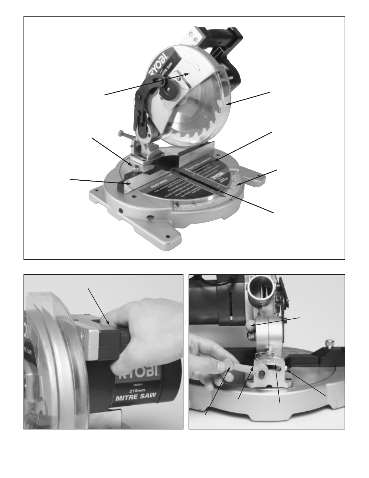
Page 5
Upper Blade Guard
Mitre Table Lock Knob
Rear Fence
Lower Blade Guard
Mitre Table
Mitre Scale
Throat Plate
■ CMS812 210mm Compound Mitre Saw
Fig.2
Fig.2a Fig.2b
Trigger Switch
Bevel Scale
45° Stopper
0° Stopper
Bevel Lock
Handle
Lock Down Pin
Page 6

Page 6
■ LOCK DOWN PIN
Your CMS812 features a lock down pin for easier
transportation. To unlock the head pull the pin out and pull the
saw arm to the upright position. (Fig 3)
■ 0 - 45° MITRE ADJUSTMENT
Your CMS812 mitre cuts from 0° to 45° both right and left,
with automatic locking of the index stopper at 5° increments.
Unlock both mitre table lock knobs and move the mitre table
to the desired cutting angle and then lock the mitre table by
securing both mitre table lock knobs. (Fig 4)
■ ON/OFF SWITCH & SAFETY GUARD
■ FENCE
The fence on your compound mitre saw has been provided to
securely hold your workpiece against when making all cuts.
■ SELF-RETRACTING LOWER BLADE GUARD
The lower blade guard provides protection from each side of
the blade. It retracts over the upper blade guard as the saw is
lowered into the workpiece.
■ ELECTRICAL CONNECTION
Your saw has a precision built electric motor. It should be
connected to a power supply that is 240 volts AC, 50-60 Hz,
only (normal household current). Do not operate this tool on
direct current (DC). A substantial voltage drop will cause a loss
of power and the motor will overheat. If your tool does not
operate when plugged into an outlet, double-check the power
supply.
WARNING: Failure to unplug your CMS812
could result in accidental starting causing
possible serious personal injury.
Fig.3
Fig.4
WARNING: The operation of any power tool can
result in foreign objects being thrown into your
eyes, which can result in severe eye damage.
Before beginning power tool operation, always
wear safety goggles or safety glasses with side
shields and a full face shield when needed. We
recommend a Wide Vision Safety Mask for use
over eyeglasses or standard safety glasses with
side shields
WARNING: Do not attempt to modify this tool
or create accessories not recommended for use
with this tool. Any such alteration or
modification is misuse and could result in
hazardous condition leading to possible serious
personal injury.
ADJUSTMENTS
■ REPLACING BLADE (Fig 5)
1. Unscrew the two screws holding the lower guard retraction
arm and remove the retraction arm. (Fig 5)
2. Unscrew the two phillips headed screws holding the lower
perspex guard and remove the guard. (Fig 5)
3. Place a piece of scrap timber under the blade and pull the
saw arm head down until the teeth of the blade lock into the
scrap timber. This will then allow you to unscrew the blade
bolt. Remove the outer flange and blade.
WARNING: To prevent accidental starting that
could cause possible serious personal injury,
assemble all parts to your saw before
connecting it to the power supply. Saw should
never be connected to power supply when you
are assembling parts, making adjustments,
installing or removing blades, or when not in
use.
DANGER: A 210 mm blade is the maximum
blade capacity of your saw. Never use a blade
that is too thick to allow outer blade washer to
engage with the flats on the spindle. Larger
blades will come in contact with the blade
guards, while thicker blades will prevent the
blade screw from securing the blade on the
spindle. Either of these situations will result in a
serious accident and can cause personal injury.
WARNING: Failure to unplug your saw could
result in accidental starting causing possible
serious personal injury.
WARNING: If the inner blade washer has been
removed, replace it before placing blade on
spindle, Failure to do so could cause an accident
since blade will not tighten properly.
Page 7

Page 7
SPECIAL NOTE
Your CMS812 mitre cutting and bevel
cutting angles have been preset at the
factory but can and will be misaligned
by rough handling and transportation.
It is essential that your new saw be
realigned before use.
Please adhere to the following resetting
instructions.
■ SQUARING THE BLADE SAW TO THE FENCE
Pull the saw arm all the way down and engage the lock down
pin to hold the saw arm in the transport position. (Fig 6)
Unlock the mitre table lock knobs. Rotate the mitre table until
the pointer is positioned at 0° position and lock the mitre table
by securing both mitre table lock knobs. (Fig 7)
Lay a set square on the mitre table and against the rear fence
and blade. If the rear fence and blade do not align adjust as
follows. (Fig 8)
Unscrew the four allen screws securing the rear pivot point to
the base and align correctly. (Fig 10)
CAUTION: Always install the blade with the
blade teeth pointing in a downward direction.
Fig.5
Screws
Phillips
Head
Screws
Fig.6
Fig.7
Fig.8
Fig.9
Fig.10
Allen Screws
Page 8

Page 8
■ SQUARING THE BLADE TO THE MITRE TABLE
Pull the saw arm all the way down and engage the lock down
pin to hold the saw arm in the transport position. (Fig 11)
Unlock the bevel lock knob and move the saw arm to the 0
position and lock the bevel lock knob. (Fig 12)
Lay the set square on the mitre table and against the blade and
if the blade and mitre table do not align adjust as follows.
(Fig 13)
Unscrew the 0° bevel positioning allen screw at the rear as
shown. (Fig 14)
Correctly align the blade and mitre table using the set square
and lock the bevel lock knob. (Fig 15)
Reset the 0° bevel positioning allen screw so where the saw
arm is moved to the 0° bevel position the allen screw bottoms
out and adjust the pointer to the 0° position (Fig 16)
■ SQUARING THE BLADE TO THE TABLE AT 45°
Repeat this procedure for squaring the blade to the mitre table
at 45° (Fig 17)
Move the saw arm to the 45° bevel position. (Fig 18)
Fig.11
Fig.12
Fig.13
Fig.14
Fig.15
Fig.16
Fig.17
Fig.18
0° Bevel Positioning
allen screw
45° Bevel Positioning
allen screw
Page 9

Page 9Page 9
If the saw arm cannot reach a full 45° position, the 45° bevel
positioning allen screw will have to be reset (Fig 18) so that
when the saw arm is moved to the 45° bevel position the allen
screw bottoms out. Check 45° angle with a 45° set square
(Fig 19) from the table to the blade. If the table and blade do
not align, readjust the 45° positioning screw (Fig 20) so that it
bottoms out at 45° and realign the bevel indication pointer
correctly (Fig 21)
■ APPLICATIONS
(Use only for the purposes listed below)
• Cross Cutting wood & plastics
• Cross Cutting mitres, joints, etc. for picture frames,
moldings, door casings and fine joinery.
NOTE: The crosscut blade provided is for most wood cutting
operations. For fine joinery and picture frame cuts or cutting
plastic, use a blade suitable, available from your nearest
hardware store.
■ CUTTING WITH YOUR COMPOUND MITRE
SAW
■ CROSSCUTTING
A crosscut is made by cutting across the grain of the
workpiece. A 90° crosscut is made with the mitre table set at
the zero degree position. Mitre crosscuts are made with the
mitre table set at some other angle other than zero.
■ TO CROSSCUT WITH YOUR MITRE SAW
• Pull out the lock pin and lift the saw arm to its full
height.
• Unlock the mitre table.
• Rotate the mitre table until the pointer aligns with
the desired angle on the mitre scale.
• Lock the mitre table handle.
NOTE: You can quickly locate 5° increments left or right on the
scale. The mitre table can be seated in one of the positive stop
notches, located in the mitre table frame.
• Place the workpiece flat on the mitre table with one edge
securely against the fence. If the board is warped, place the
convex side against the fence and clamp. If the concave
edge of a board is placed against the fence, the board could
collapse on the blade at the end of the cut, jamming the
blade. (Fig 22)
Fig.19
Fig.20
Fig.21
WARNING: Before starting any cutting
operations, clamp or bolt your compound mitre
saw to a workbench. Never operate your mitre
saw on the floor or in a crouched position.
Failure to heed this warning can result in serious
personal injury
OPERATIONS
WARNING: Use a clamp to secure your
workpiece on one side of the blade only. The
workpiece must remain free on one side of the
blade to prevent the blade from binding in
workpiece. The workpiece binding blade will
cause motor stalling and kickback. This
situation could cause an accident resulting in
serious personal injury.
Fig.22
Page 10

Page 10
• When cutting long pieces of timber or molding, support the
opposite end of the stock.
• Align cutting line on the workpiece with the edge of saw
blade.
• Grasp the stock firmly with one hand and secure it against
the fence.
• Before turning on the saw, perform a dry run of the cutting
operation just to make sure that no problems will occur
when the cut is made.
• Grasp the saw handle firmly, then squeeze the switch
trigger. Allow several seconds for the blade to reach
maximum speed.
• Slowly lower the blade into and through the workpiece.
• Release the switch trigger and allow the saw blade to stop
rotating before raising the blade out of the workpiece.
■ BEVEL CUT
A bevel cut is made by cutting across the grain of the
workpiece with the blade angled to the fence and mitre table.
A bevel cut is made with the mitre table set at zero degree
position and the blade set at an angle between 0° and 45°
(Fig 23)
■ TO BEVEL CUT WITH YOUR MITRE SAW
• Pull out the lock pin and lift the saw arm to its full height.
• Loosen the mitre table locking knobs.
• Rotate the mitre table until the pointer aligns with zero on
the mitre scale.
• Lock the mitre table by securing the two mitre table lock
knobs.
• Loosen the bevel lock handle and move the saw arm to the
left to the desired bevel angle.
• Bevel angles can be set from 0° to 45°
• Align the indicator point with the desired angle.
• Once the saw arm has been set at the desired angle,
securely tighten the bevel lock handle.
• Place the workpiece flat on the mitre table with one warped,
place the convex against the fence. If the board is warped,
place the convex side against the fence. If the concave edge
of the board is placed against the fence, the board could co
lapse on the blade at the end of the cut, jamming the blade.
• When cutting long pieces of timber or molding, support the
overhanging end(s) of the stock.
• Align the cutting line on the workpiece with the edge of saw
blade.
• Grasp the stock firmly with one hand and secure it against
the fence.
• Before turning on the saw, perform a dry run of the cutting
operation just to make sure that no problems will occur
when the cut is made.
• Grasp the saw handle firmly, then squeeze the switch
trigger. Allow several seconds for the blade to reach
maximum speed.
• Slowly lower the blade into and through the workpiece.
• Release the switch trigger and allow the saw blade to stop
rotating before raising the blade out of workpiece.
■ COMPOUND MITRE CUT
A compound mitre cut is a cut made using a mitre angle and a
bevel angle at the same time. This type of cut is used to make
picture frames, cut moulding, make boxes with sloping sides,
and for certain roof framing cuts.
To make this type of cut the mitre table must be rotated to the
correct angle and the saw arm must be tilted to the correct
bevel angle. Care should always be taken when making
compound mitre setups due to the interaction of the two angle
settings.
Adjustments of mitre and bevel settings are interdependent
with one another. Each time you adjust the mitre setting you
change the effect of the bevel setting. Also, each time you
adjust the bevel setting you change the effect of the mitre
setting.
It may take several settings to obtain the desired cut. The first
angle setting should be checked after setting the second
angle, since adjusting the second angle affects the first.
Once the two correct settings for a particular cut have been
obtained, always make a test cut in scrap wood before making
a finish cut in good wood. (Fig 24)
WARNING: To avoid serious personal injury
keep your hands outside the no hands zone; at
least 75mm from blade. Never perform any
cutting operation freehand (without holding
workpiece against the fence). The blade could
grab the workpiece if it slips or twists
WARNING: To avoid serious personal injury,
always push the mitre table clamp back down
before making a cut. Failure to do so could
result in movement of the mitre table while
making a cut causing serious personal injury.
WARNING: To avoid serious personal injury,
keep your hands outside the no hands zone; at
least 75mm from the blade. Never perform any
cutting operation free-hand (without holding
workpiece against the fence). The blade could
grab the workpiece if it slips or twists.
Fig.23
Page 11

■ TO MAKE A COMPOUND CUT WITH YOUR
MITRE SAW
• Pull out the lock pin and lift the saw arm to its full height.
• Loosen the mitre table locking knobs.
• Rotate the mitre table until the pointer aligns with the
desired angle on the mitre scale and lock both mitre table
lock knobs.
NOTE: You can quickly locate 5° increments left or right on the
scale. The mitre table can be seated in one of the positive stop
notches, located in the mitre table frame.
• Loosen the bevel lock handle and move the saw arm to the
left to the desired bevel angle.
• Bevel angles can be set from 0° to 45°
• Align the indicator point with the desired angle.
• Once the saw arm has been set at the desired angle,
securely tighten the bevel lock handle.
• Recheck mitre angle setting. Make a test cut in scrap
material
• Place the workpiece flat on the mitre table with one edge
securely against the fence. If the board is warped, place the
convex side against the fence. If the concave edge of the
board is placed against the fence, the board could collapse
on the blade at the end of the cut, jamming the blade.
(Fig 25).
• When cutting long pieces of timber or molding, support the
opposite end of the stock with a roller stand or with work
surface level with the saw table.
• Align the cutting line on the workpiece with the edge of the
saw blade.
• Grasp the stock firmly with one hand and secure it against
the fence.
• Before turning on the saw, perform a dry run of the cutting
operation just to make sure that no problems will occur
when the cut is made.
• Grasp the saw handle firmly, then squeeze the switch
trigger. Allow several seconds for blade to reach maximum
speed.
• Slowly lower the blade into and through the workpiece.
• Release the switch trigger and allow the saw blade to stop
rotating before raising the blade out of workpiece.
Page 11
Fig.24
WARNING: To avoid serious personal injury,
always lock the mitre table before making a cut.
Failure to do so could result in movement of the
mitre table while making a cut.
WARNING: To avoid serious personal injury,
always keep your hands outside the no hands
zone; at least 75mm from the blade. Never
perform a cutting operation freehand (without
holding the workpiece against the fence). The
blade could grab the workpiece if it slips or
twists.
Fig.25
Page 12

Page 12
■ CUTTING CROWN MOLDING
Your compound mitre saw does an excellent job of cutting
crown molding. In general, compound mitre saws do a better
job of cutting crown molding than any other tool made.
In order to fit properly, crown molding must be compound
mitred with extreme accuracy.
The two contact surfaces on a piece of crown molding that fit
flat against the ceiling and the wall of a room are at angles
that, when added together equal exactly 90°.
Most crown molding has a top rear angle (the section that fits
flat against the ceiling) of 52° and a bottom rear angle (the
section that fits flat against the wall) of 38°.
■ LAYING MOLDING FLAT ON THE MITRE
TABLE
To use this method for accurately cutting crown molding for a
90° inside or outside corner, lay the molding with its broad
back surface flat on the mitre table and against the fence.
When setting the bevel and mitre angles for compound
mitres, remember that the settings are interdependent,
changing one angle changes the other angle as well.
Keep in mind that the angles for crown moldings are very
precise and difficult to set. Since it is very easy for these
angles to shift, all settings should first be tested on a scrap
molding. Also most walls do not have angles of exactly 90°,
therefore, you will need to finetune your settings.
Page 13

Page 13
When cutting crown molding by this method the bevel angle
should be set at 33.85°. The mitre angle should be set at
31.62° either right or left, depending on the desired cut for the
application. See the chart below for correct angle settings and
correct positioning of crown molding on mitre table.
The settings in the chart below can be used for cutting all
standard crown moulding with 52° and 38° angles. The crown
moulding is placed flat on the mitre table using the compound
features of your mitre saw.
■ CUTTING WARPED MATERIAL
(See Figures 26 & 27)
When cutting warped material, always make sure it is
positioned on the mitre table with the convex side against the
fence as shown in figure 26.
If the warped material is positioned the wrong way as shown
in figure 27, it will pinch the blade near the completion of the
cut.
Bevel
Angle Type of Cut
Setting
Left Side, inside corner
1. Top edge of moulding against fence
2. Mitre table set right 31.62°
3. Save left end of cut
Right Side, inside corner
1. Bottom edge of moulding against fence
2. Mitre table set left 31.62°
3. Save left end of cut
Left Side, outside corner
1. Bottom edge of moulding against fence
2. Mitre table set left 31.62°
3. Save right end of cut
Right Side, outside corner
1. Top edge of moulding against fence
2. Mitre table set left 31.62°
3. Save right end of cut
33.85°
33.85°
33.85°
33.85°
RIGHT
Fig.26
WRONG
Fig.27
WARNING: To avoid a kickback and to avoid
serious personal injury, never position the
concave edge of bowed or warped material
against the fence.
Page 14

Page 14
NOTES:
Page 15

HOME USE WARRANTY
24 Months Home Use Warranty
Subject to the warranty conditions below, this RYOBI
tool, (hereinafter called "the product"), is warranted for
home use only by Ryobi Australia Pty. Ltd. (hereinafter
called "The Company") to be free from defects in
material or workmanship for a period of 24 months from
the date of original purchase covering both parts and
labour. Under the terms of this warranty, the repair or
replacement of any part shall be the opinion of the
Company or its authorised agent. Should service
become necessary during the warranty period, the
owner should return the product to their nearest
authorised RYOBI Service Centre. In order to obtain
warranty service, the owner must include the Sales
Docket and Warranty Certificate to confirm date of
purchase. This Product is sold by the dealer or agent as
principal and the dealer has no authority from the
Company to give any additional warranty or guarantee
on the Company's behalf except as herein contained or
herein referred to.
Warranty Conditions
This warranty only applies provided that the Product has
been used in accordance with the manufacturer's
recommendations under normal use and reasonable
care (in the opinion of the Company) and such warranty
does not cover consumable components, damage,
malfunction or failure resulting from misuse, neglect,
abuse, or used for a purpose for which it was not
designed or is not suited and no repairs, alterations or
modifications have been attempted by other than an
Authorised Service Agent. This guarantee will not apply
if the tool is damaged by accident or if repairs arise from
normal wear and tear. The Company accepts no
additional liability pursuant to this warranty for the costs
of travelling or transportation of the Product or parts to
and from the service dealer or agent - which costs are
not included in this warranty. Certain legislation,
including the Trade Practices Act, 1974 (as amended)
and other state and territorial laws give rights to the
buyer and impose liability on the seller in certain
circumstances. Nothing herein shall have the effect of
excluding, restricting or modifying any condition,
warranty, right or liability imposed, to the extent only
that such exclusion, restriction or modification would
render any term herein void.
30 Day Satisfaction Guarantee
If the owner is not completely satisfied with the
performance of the product, for quality reasons, the
Product should be returned to the Authorised RYOBI
Dealer from whom it was purchased within 30 days of
the original date of purchase for refund or exchange.
RYOBI AUSTRALIA PTY. LTD.
A.B.N. 98 002 277 509
SYDNEY: 359-361 Horsley Road, Milperra, N.S.W. 2214.
Contact during normal business hours.
Tel: (02) 9792 9888 - Fax: 1800 807 993 - Email: info@ryobi.aust.com
Web Site: www.ryobi.com.au
RYOBI NEW ZEALAND PTY. LTD.
AUCKLAND: 503 Mt Wellington Highway, Mt Wellington, N.Z.
Tel: (09) 573 0230 - Free Call: 0800 279 624 - Fax: (09) 573 0231 - Email: info@ryobi.co.nz
Contact during normal business hours.
BRISBANE: All enquiries Tel : 1300 361 505
TOWNSVILLE: All enquires Tel : 1300 361 505
MELBOURNE: 960 Stud Road, Rowville.Vic. 3178
Tel : (03) 9764 8655
HOBART: All enquiries Tel : 1300 360 216
ADELAIDE: All enquiries Tel : 1300 360 216
PERTH: 33-35 Sorbonne Cres.,Canning Vale. W.A. 6155.
Tel : (08) 9455 7775
THIS WARRANTY FORM SHOULD BE RETAINED BY THE CUSTOMER AT ALL TIMES.
For your record and to assist in establishing date of purchase (necessary for in-warranty service),
please keep your purchase docket and this form, completed with the following particulars.
PURCHASED FROM :........................................................................................................................................................
ADDRESS OF DEALER : ..................................................................................................................................................
DATE: ................................MODEL NO.: ....................................................SERIAL NO.: ................................................
Present this form with your Purchase Docket when Warranty Service is required.
 Loading...