

Page 1
OPERATOR’S MANUAL
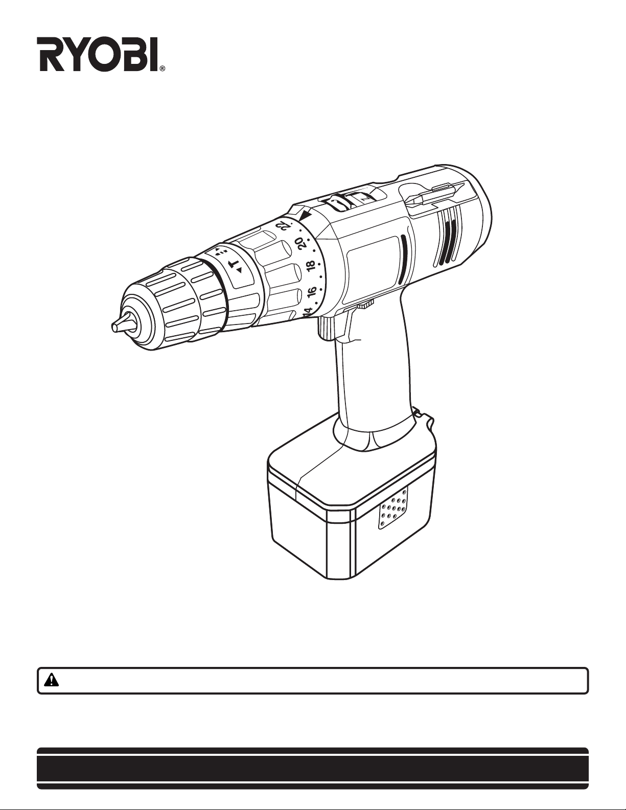
CORDLESS IMPACT DRILL-DRIVER
MODEL NO. CID1442P/CID1802P
THANK YOU FOR BUYING A RYOBI CORDLESS IMPACT DRILL-DRIVER.
our new cordless impact drill-driver has been engineered and manufactured to Ryobi’s high standard for dependability, ease of
Y
operation, and operator safety. Properly cared for, it will give you years of rugged, trouble-free performance.
CAUTION: Carefully read through this entire operator's manual before using your new cordless impact drill-driver
Pay close attention to the Rules for Safe Operation, W
and only for what it is intended, you will enjoy years of safe, reliable service.
Thank you again for buying Ryobi tools.
arnings, and Cautions. If you use your cordless impact drill-driver properly
SAVE THIS MANUAL FOR FUTURE REFERENCE
.
Page 2
TABLE OF CONTENTS
■ General Safety Rule ................................................................................................................................................ 2-3
■ Specific Safety Rules/Symbols ................................................................................................................................ 3-5
■ Features ..................................................................................................................................................................... 5
■ Specifications ............................................................................................................................................................. 6
■ Important Information For Recharging Hot Batteries .................................................................................................. 6
■ Operation ............................................................................................................................................................... 7-12
■ Maintenance ............................................................................................................................................................. 13
■ Guarantee .................................................................................................................................................................14
GENERAL SAFETY RULES
Personal Safety
WARNING:
Read and understand all instructions. Failure to follow
all instructions listed below, may result in electric shock,
fire and/or serious personal injury.
SAVE THESE INSTRUCTIONS
Work Area
■ Keep your work area clean and well lit. Cluttered
benches and dark areas invite accidents.
■ Do not operate power tools in explosive atmospheres, such as in the presence of flammable liquids, gases, or dust. Power tools create sparks which
may ignite the dust or fumes.
■ Keep bystanders, children, and visitors away while
operating a power tool. Distractions can cause you to
lose control.
Electrical Safety
■ Do not abuse the cord. Never use the cord to carry
the charger. Keep cord away from heat, oil, sharp
edges, or moving parts. Replace damaged cords
immediately. Damaged cords may create a fire.
■ A battery operated tool with integral batteries or a
separate battery pack must be recharged only with
the specified charger for the battery. A charger that
may be suitable for one type of battery may create a risk
of fire when used with another battery. Use battery only
with charger listed.
MODEL BATTERY
CID1442P 1311166 1426804
CID1802P
■ Use battery operated tool only with specifically
designated battery pack. Use of any other batteries
may create a risk of fire. Use only with battery pack listed.
1310918 2601038
CHARGING ASSEMBLY/CHARGER
■ Stay alert, watch what you are doing and use common sense when operating a power tool. Do not use
tool while tired or under the influence of drugs, alcohol, or medication. A moment of inattention while
operating power tools may result in serious personal injury.
■ Dress properly. Do not wear loose clothing or jewelry. Contain long hair. Keep your hair, clothing, and
gloves away from moving parts. Loose clothes, jew-
elry, or long hair can be caught in moving parts.
■ Avoid accidental starting. Be sure switch is in the
locked or off position before inserting battery pack.
Carrying tools with your finger on the switch or inserting
the battery pack into a tool with the switch on, invites
accidents.
■ Remove adjusting keys or wrenches before turning
the tool on. A wrench or a key that is left attached to a
rotating part of the tool may result in personal injury.
■ Do not overreach. Keep proper footing and balance
at all times. Proper footing and balance enable better
control of the tool in unexpected situations. Do not use
on a ladder or unstable support.
■ Use safety equipment. Always wear eye protection.
Dust mask, non-skid safety shoes, hard hat, or hearing
protection must be used for appropriate conditions.
Page 2
Page 3

GENERAL SAFETY RULES
Tool Use and Care
■ Use clamps or other practical way to secure and
support the workpiece to a stable platform. Holding
the work by hand or against your body is unstable and
may lead to loss of control.
■ Do not force tool. Use the correct tool for your application. The correct tool will do the job better and safer
at the rate for which it is designed.
■ Do not use tool if switch does not turn it on or off. A
tool that cannot be controlled with the switch is dangerous and must be repaired.
■ Disconnect battery pack from tool before making any adjustments, changing accessories, or storingthetool. Such
preventive safety measures reduce risk of starting the tool
accidentally .
■ Store idle tools out of reach of children and other
untrained persons. Tools are dangerous in the hands
of untrained users.
■ When battery pack is not in use, keep it away from
other metal objects like: paper clips, coins, keys,
nails, screws, or other small metal objects that can
make a connection from one terminal to another.
Shorting the battery terminals together may cause
sparks, burns, or a fire.
■ Maintain tools with care. Keep cutting tools sharp
and clean. Properly maintained tools, with sharp cutting
edges are less likely to bind and are easier to control.
■ Check for misalignment or binding of moving parts,
breakage of parts, and any other condition that may
affect the tool's operation. If damaged, have the tool
serviced before using. Many accidents are caused by
poorly maintained tools.
■ Use only accessories that are recommended by the
manufacturer for your model. Accessories that may
be suitable for one tool, may create a risk of injury when
used on another tool.
Service
■ Tool service must be performed only by authorized
repair personnel. Service or maintenance performed
by unqualified personnel could result in a risk of injury.
■ When servicing a tool, use only identical replacement parts. Follow instructions in the Maintenance
section of this manual. Use of unauthorized parts or
failure to follow Maintenance Instructions may create a
risk of shock or injury.
SPECIFIC SAFETY RULES AND/OR SYMBOLS
Hold tool by insulated gripping surfaces when performing an operation where the cutting tool may contact hidden
wiring. Contact with a "live" wire will make exposed metal parts of the tool "live" and shock the operator.
Additional Rules For Safe Operation
■ Know your power tool. Read operator's manual carefully. Learn its applications and limitations, as well
as the specific potential hazards related to this tool.
Following this rule will reduce the risk of electric shock,
fire, or serious injury.
■ Make sure your extension cord is in good condition.
When using an extension cord, be sure to use one
heavy enough to carry the current your product will
draw. A wire gage size (A.W.G.) of at least 16 is
recommended for an extension cord 100 feet or less
in length. A cord exceeding 100 feet is not recommended. If in doubt, use the next heavier gage. The
smaller the gage number, the heavier the cord. An
undersized cord will cause a drop in line voltage resulting in loss of power and overheating.
Important Rules for Battery Tools
■ Battery tools do not have to be plugged into an
electrical outlet; therefore, they are always in operating condition. Be aware of possible hazards when
not using your battery tool or when changing accessories. Following this rule will reduce the risk of electric
shock, fire, or serious personal injury.
■ Do not place battery tools or their batteries near fire
or heat. This will reduce the risk of explosion and
possible injury.
■ Do not charge battery tool in a damp or wet location.
Following this rule will reduce the risk of electric shock.
■ For best results, your battery tool should be charged
in a location where the temperature is between 10
and 37
■ Under extreme usage or temperature conditions,
battery leakage may occur. If liquid comes in contact
with your skin, wash immediately with soap and
water, then neutralize with lemon juice or vinegar. If
liquid gets into your eyes, flush them with clean
water for at least 10 minutes, then seek immediate
medical attention. Following this rule will reduce the
risk of serious personal injury.
C.
C
Page 3
Page 4
SPECIFIC SAFETY RULES AND/OR SYMBOLS
Important Safety Instructions For Charger
■ Save these instructions. This manual contains important safety and operating instructions for charger.
Following this rule will reduce the risk of electric shock,
fire, or serious personal injury.
■ Before using battery charger, read all instructions
and cautionary markings in this manual, on battery
charger, and product using battery charger. Follow-
ing this rule will reduce the risk of electric shock, fire, or
serious personal injury.
■ To reduce risk of injury, charge only nickel-cadmium type rechargeable batteries. Other types of
batteries may burst causing personal injury and
damage. Following this rule will reduce the risk of
electric shock, fire, or serious personal injury.
■ Do not expose charger to rain or snow.Following this
rule will reduce the risk of electric shock, fire, or serious
personal injury.
■ Use of an attachment not recommended or sold by
the battery charger manufacturer may result in a risk
of fire, electric shock, or injury to persons. Following
this rule will reduce the risk of electric shock, fire, or
serious personal injury.
■ To reduce risk of damage to charger body and cord,
pull by charger plug rather than cord when disconnecting charger. Following this rule will reduce the risk
of electric shock, fire, or serious personal injury.
■ Make sure cord is located so that it will not be
stepped on, tripped over, or otherwise subjected to
damage or stress. Following this rule will reduce the
risk of serious personal injury.
■ An extension cord should not be used unless absolutely necessary. Use of improper extension cord
could result in a risk of fire and electric shock. If extension cord must be used, make sure:
a. That pins on plug of extension cord are the
same number, size and shape as those of
plug on charger.
b. That extension cord is properly wired and in
good electrical condition; and
c. That wire size is large enough for AC ampere
rating of charger.
■ Do not operate charger with a damaged cord or plug.
If damaged, have replaced immediately by a qualified serviceman. Following this rule will reduce the risk
of electric shock, fire, or serious personal injury.
■ Do not operate charger if it has received a sharp
blow, been dropped, or otherwise damaged in any
way; take it to a qualified serviceman. Following this
rule will reduce the risk of electric shock, fire, or serious
personal injury.
■ Do not disassemble charger; take it to a authorized
serviceman when service or repair is required. Incorrect reassembly may result in a risk of electric
shock or fire. Following this rule will reduce the risk of
electric shock, fire, or serious personal injury.
■ To reduce the risk of electric shock, unplug charger
from outlet before attempting any maintenance or
cleaning. Turning off controls will not reduce this
risk. Following this rule will reduce the risk of electric
shock, fire, or serious personal injury.
■ Disconnect charger from power supply when not in
use. Following this rule will reduce the risk of electric
shock, fire, or serious personal injury.
DANGER:
RISK OF ELECTRIC SHOCK. DO NOT TOUCH
UNINSULATED PORTION OF OUTPUT CONNECTOR
OR UNINSULATED BATTERY TERMINAL.
■ Save these instructions. Refer to them frequently
and use them to instruct others who may use this
tool. If you loan someone this tool, loan them these
instructions also. Following this rule will reduce the risk
of electric shock, fire, or serious personal injury.
Page 4
Page 5
WARNING:
Somedust created bypower sanding, sawing,grinding,drilling, and otherconstruction activities containschemicals
known to cause cancer, birth defects or other reproductive harm. Some examples of these chemicals are:
• lead from lead-based paints,
• crystalline silica from bricks and cement and other masonry products, and
• arsenic and chromium from chemically-treated lumber.
Your risk from these exposures varies, depending on how often you do this type of work. To reduce your exposure
to these chemicals: work in a well ventilated area, and work with approved safety equipment, such as those dust
masks that are specially designed to filter out microscopic particles.
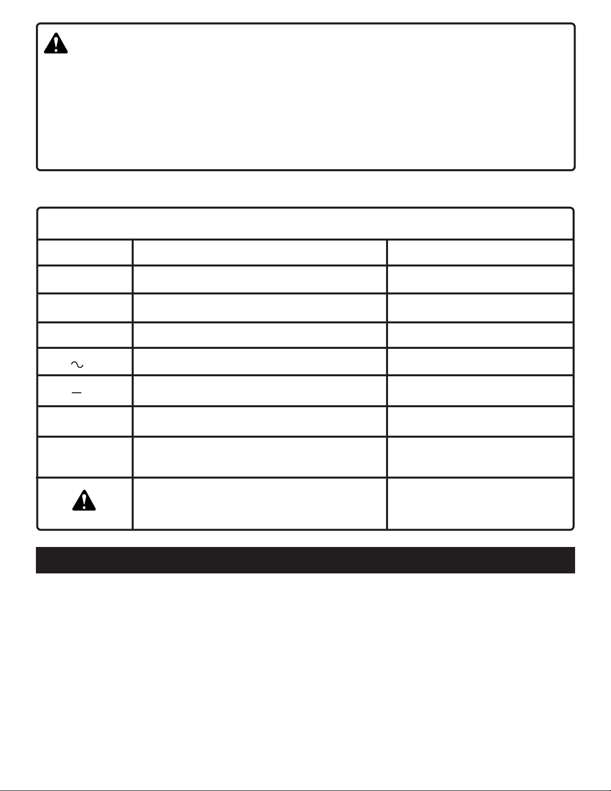
SYMBOLS
SYMBOL NAME DESIGNATION/EXPLANATION
V Volts Voltage
A Amperes Current
Hz Hertz Frequency (cycles per second)
min Minutes Time
Alternating Current Type or a characteristic of current
--- Direct Current Type or a characteristic of current
n
0
.../min Revolutions or Reciprocation Per Minute Revolutions, strokes,
No Load Speed Rotational speed, at no load
surface speed, orbits etc. per minute
Safety Alert Symbol Indicates danger, warning or caution.
It means attention!!! Your safety is
involved.
FEATURES
DEFINITIONS
A) DANGER: Failure to obey a safety warning will result in serious injury to yourself or to others.
Always follow the safety precautions to reduce the risk of fire, electric shock and personal injury.
B) WARNING: Failure to obey a safety warning can result in serious injury to yourself or to others.
Always follow the safety precautions to reduce the risk of fire, electric shock and personal injury.
C) CAUTION: Failure to obey a safety warning may result in property damage or personal injury
to yourself or to others. Always follow the safety precautions to reduce the risk of fire, electric
shock and personal injury.
D) NOTE: Advises you of information or instructions vital to the operation or maintenance of the
equipment.
Page 5
Page 6

SPECIFICATIONS:
CID1442P
Chuck
Motor
Switch
No Load Speed
10mm Keyless
14.4V DC 700
Variable Speed
0 - 350 RPM (Low)
0 - 1250 RPM (High)
Impact Speed
0 - 5600 BPM (Low)
0 - 20000 BPM (High)
Clutch
Charger Input
Charge Rate
IMPORTANT INFORMATION FOR RECHARGING HOT BATTERIES
When using your drill-driver continuously, the batteries in
your battery pack become hot. You should let a hot battery
pack cool down for approximately 30 minutes before attempting to recharge.
Note: This situation occurs when continuous use of your
drill-driver causes the batteries to become hot. It does not
24 Positions
240V, 50 Hz, AC Only
3-6 Hours
CID1802P
10mm Keyless
18V DC 700
Variable Speed
0 - 400 RPM (Low)
0 - 1400 RPM (High)
0 - 6400 BPM (Low)
0 - 22400 BPM (High)
24 Positions
240V, 50 Hz, AC Only
1 Hour
occur under normal circumstances. Refer to "Charging
Your Impact Drill-Driver" for normal recharging of batteries. If the
charger/charging assembly does not charge your battery
pack under normal circumstances, return both the battery
pack and charger/charging assembly to your nearest Ryobi
Authorized Service Center for electrical check.
WARNING:
The operation of any power tool can result in foreign objects being thrown into your
eyes, which can result in severe eye damage. Before beginning power tool operation,
always wear safety goggles or safety glasses with side shields and a full face shield
when needed. We recommend Wide Vision Safety Mask for use over eyeglasses or
standard safety glasses with side shields.
Page 6
Page 7

OPERATION
MODEL CID1442P
KNOW YOUR IMPACT DRILL-DRIVER
See Figure 1.
Before attempting to use any tool, familiarize yourself with all
operating features and safety requirements.
W ARNING:
Do not allow familiarity with tools to make you careless.
Remember that a careless fraction of a second is
sufficient to inflict severe injury.
CHARGING YOUR IMPACT DRILL-DRIVER
The battery pack for this tool has been shipped in a low
charge condition to prevent possible problems. Therefore,
you should charge it at least 6 hours prior to use.
Note: Batteries will not reach full charge the first time they
are charged. Allow several cycles (drilling followed by recharging) for them to fully charge.
TO CHARGE
■ Charge battery pack only with the charging assembly
provided.
■ Make sure power supply is normal household voltage, 240 volts, 50 Hz, AC only.
■ Connect charging assembly to power supply.
■ Place battery pack in charging assembly. Align raised
rib on battery pack with groove in charging assembly.
See Figure 1A.
■ Press down on battery pack to be sure contacts on
battery pack engage properly with contacts in charging
assembly. When properly connected, red light will turn on.
■ After normal usage, 3 hours of charging time is required to be fully charged. A minimum charge time of 6
hours is required to recharge a completely discharged
battery.
The battery pack will become slightly warm to the touch
■
while charging. This is normal and does not indicate a
problem.
■ DO NOT place charging assembly in an area of ex-
treme heat or cold. It will work best at normal room
temperature.
■ When battery pack has been charged, disconnect charging assembly from power supply and remove the battery
pack. This practice will increase battery life.
TWO SPEED GEAR TRAIN
See Figure 1B.
Your drill has a two-speed gear train designed for drilling or
driving at LO (1) or HI (2) speeds. A slide switch is located
on top of your drill to select either LO (1) or HI (2) speed.
When using drill in the LO (1) speed range, speed will
decrease and unit will have more power and torque. When
using drill in the HI (2) speed range, speed will increase
and unit will have less power and torque. Use LO (1) speed
for high power and torque applications and HI (2) speed for
fast drilling or driving applications.
Page 7
Page 8

OPERATION
MODEL CID1802P
LED FUNCTION OF CHARGER 2601038
See Figure 2..
LED WILL BE LIGHTED TO INDICATE STATUS OF
CHARGER AND BATTERY PACK:
Red LED lighted = Fast Charging Mode
Green LED lighted = Fully Charged Battery Pack
Yellow and Green LED Lighted = Control Charge or
Defective Battery Pack.
CHARGING BATTERY PACK
The battery pack for this tool has been shipped in a low
charge condition to prevent possible problems. Therefore,
you should charge it prior to use.
NOTE: Batteries will not reach full charge the first time they
are charged. Allow several cycles (cutting followed by recharging) for them to fully charge.
Charge battery pack only with the charger provided.
Make sure power supply is normal house voltage,
240 Volts, 50 Hz, AC only.
Connect charger to power supply.
Place battery pack in charger.
rib on battery pack with groove in charger.
Press down on battery pack to be sure contacts on
battery pack engage properly with contacts in charger.
When properly connected, red light will turn on.
Normally, the yellow and green lights on the charger will
come on. This indicates charger is in control charge
mode and should switch to fast charge mode within 5
minutes. When charger is in fast charge mode the red
light will come on. If after a period of 15 minutes the
yellow and green lights remain on, remove the battery
pack, wait 1 minute and reinsert battery pack in charger.
If the yellow and green lights continue to remain on an
additional 15 minutes, the battery pack is damaged and
will not accept charge.
When your battery pack becomes fully charged, the red
light will turn off and the green light will turn on.
After normal usage, 1 hour of charge time is required to
be fully charged. A minimum charge time of 1 to 1-1/2
hours is required to recharge a completely discharged
tool.
The battery pack will become slightly warm to the touch
while charging. This is normal and does not indicate a
problem.
Do not place charger in an area of extreme heat or cold.
It will work best at normal room temperature.
When the batteries become fully charged, unplug your
charger from power supply and remove the battery pack.
See Figure A.
Align raised
Fig.
2
IMPORTANT SAFETY WARNING!!
CORDLESS CUTTING TOOLS CAN BE EXTREMELY
DANGEROUS
IF NOT HANDLED CORRECTLY AND WITH PROPER CAUTION.
Once the battery pack is attached to the cutting tool, the cutting
Use extreme caution when operating the tools.
Never leave the battery pack attached when the tool is not in use.
Never get into the habit of activating the trigger switch when* *
you do not intend to use the tool immediately.
Always keep out of reach of children and never let * *
inexperienced user operate the tool without them firstly
thoroughly reading and understanding the safety and
operating instructions in the owners manual.
Never leave the battery pack attached to the tool when
changing blade or making setting adjustments to the tools.
The appliance is not intended for use by young children or
infirm persons without supervision.
Young children should be supervised to ensure that they do *
not play with the appliance.
Page 8
Failure to follow these safety instructions can
result in accidental starting, causing serious
injury to your self or others.
Page 9

OPERATION
WARNING:
If any parts are missing, do not operate tool until the
missing parts are replaced. Failure to do so could result
in possible serious personal injury.
SWITCH
See Figure 3.
Your drill starts and stops by depressing and releasing the
switch trigger.
Your drill has a variable speed feature in the switch. The
switch delivers higher speed and torque with increased
trigger pressure. Speed is controlled by the amount of
switch trigger depression.
SWITCH LOCK
See Figure 3.
The switch trigger can be locked in the OFF position. This
feature helps reduce the possibility of accidental starting
when not in use. To lock the switch trigger, place the direction
of rotation selector in the center position.
TO INSTALL BATTERY PACK
■ Place the direction of rotation selector in center posi-
See Figure 3.
tion.
■ Place the battery pack in your drill. Align raised rib on
battery pack with groove in drill's battery port.
ure 4.
■ Make sure the latches on each side of your battery pack
snap in place and that battery pack is secured in drill
before beginning operation.
See Fig-
TO REMOVE BATTERY PACK
■ Place the direction of rotation selector in center posi-
See Figure 3.
tion.
■ Locate latches on side of battery pack and depress both
sides to release battery pack from your drill.
4.
■ Remove battery pack from your drill.
See Figure
CAUTION:
When placing battery pack in your drill, be sure raised
rib on battery pack aligns with groove in drill's battery
port and latches snap in place properly. Improper
assembly of battery pack can cause damage to internal
components.
Page 9
Page 10

OPERATION
REVERSIBLE
See Figure 3.
This tool is reversible. The direction of rotation is controlled
by a selector located above the switch trigger. With the drill
held in normal operating position, the direction of rotation
selector should be positioned to the left of the switch for
drilling. The drilling direction is reversed when the selector is
to the right of the switch. When the selector is in center
position, the switch trigger is locked.
CAUTION:
To prevent gear damage, always allow chuck to come to
a complete stop before changing the direction of rotation.
To stop, release switch trigger and allow the chuck to come
to a complete stop.
WARNING:
Battery tools are always in operating condition. Therefore,
switch should always be locked when not in use or when
carrying at your side.
Fig. 5
KEYLESS CHUCK
See Figure 5.
A keyless chuck has been provided with your drill to allow for
easy installation and removal of bits. As the name implies,
you can hand tighten or release drill bits in the chuck jaws.
Grasp and hold the collar of the chuck with one hand. Rotate
the chuck body with your other hand. The arrows on the
chuck indicate which direction to rotate the chuck body in
order to GRIP (tighten) or RELEASE (unlock) the drill bit.
WARNING:
Do not hold the chuck body with one hand and use the
power of the drill to tighten chuck jaws on drill bits. Chuck
body could slip in your hand or your hand could slip and
come in contact with rotating drill bit. This could cause
an accident resulting in serious personal injury.
INSTALLING BITS
■ Place the direction of rotation selector in center position.
See Figure 3.
■ Open or close the chuck jaws to a point where the
opening is slightly larger than the bit size you intend to
use. Also, raise the front of your drill slightly to keep the
bit from falling out of the chuck jaws.
■ Insert your drill bit into the chuck the full length of the
See Figure 6.
jaws.
■ Tighten the chuck jaws on the drill bit. To tighten, grasp
and hold the collar of the chuck with one hand, while
rotating the chuck body with your other hand.
This will turn off the power to your drill.
Fig. 6
Fig. 7
Note: Rotate the chuck body in the direction of the arrow
marked GRIP to tighten the chuck jaws. DO NOT use a
wrench to tighten or loosen the chuck jaws.
WARNING:
Do not insert drill bit into chuck jaws and tighten as shown
in figure 7. This could cause drill bit to be thrown from
drill resulting in possible serious personal injury or
damage to the chuck.
Page 10
Page 11

OPERATION
REMOVING BITS
See Figure 6.
■ Place the direction of rotation selector in center position.
See Figure 3.
■ Loosen the chuck jaws from drill bit
■ To loosen: grasp and hold the collar of the chuck with
one hand, while rotating chuck body with your other hand.
Note: Rotate chuck body in the direction of the arrow
marked RELEASE to loosen chuck jaws.
■ DO NOT use a wrench to tighten or loosen the chuck jaws.
■ Remove drill bit from chuck jaws.
SCREWDRIVING
TORQUE ADJUSTMENT
(Driving power of your drill-driver)
When using your drill-driver for various driving aplications, it
becomes necessary to increase or decrease the torque in
order to help prevent the possibility of damaging screw
heads, threads, workpiece, etc. In general, torque should
correspond to the intensity of the screw diameter. If the
torque is too high or the screws too small, the screws may be
damaged or broken.
The torque is adjusted by rotating the torque adjustment ring.
See Figure 8.
ment ring is set on a higher setting. The torque is less when
the torque adjustment ring is set on a lower setting.
The proper setting depends on the type of material and the
size of screw you are using.
TO ADJUST TORQUE
■ Identify the twenty four torque indicator settings located
on the front of your drill.
■ Rotate adjustment ring to the desired setting.
• 1 - 4 For driving small screws.
• 5 - 8 For driving screws into soft material.
• 9 - 12 For driving screws into soft and hard
• 13 - 16 For driving screws in hard wood.
• 17 - 20 For driving large screws.
••21 - For heavy drilling.
For impact drilling
This will turn off the power to your drill.
.
The torque is greater when the torque adjust-
See Figure 8.
materials.
BIT STORAGE
See Figure 9a.
When not in use, bits provided with your drill can be placed
in the storage area located on the top of your drill as shown
in figure 9a.
IMPACT ACTION
See Figure 9b.
The drilling action on models CID1442P and CID1802P can
be altered to hammer action mode for drill masonry by turning
the mode dial located at the front of the torque
control mechanism.
Simply turning the dial to align the small hammer with the
arrow shifts the drill into hammer action mode. For best results
please use High Gear and specialised Masonry drill bits.
Page 11
Page 12

OPERATION
W ARNING:
Always wear safety goggles or safety glasses with side
shields when operating tool. Failure to do so could result
in objects being thrown into your eyes, resulting in
possible serious injury.
DRILLING
See Figure 10.
When drilling hard, smooth surfaces, use a center punch to
mark the desired hole location. This will prevent the drill bit
from slipping off center as the hole is started. However, the
lower speed feature allows starting holes without center
punching if desired. To accomplish this, simply operate your
drill at lower speed until the hole is started.
The material to be drilled should be secured in a vise or with
clamps to keep it from turning as the drill bit rotates.
Hold tool firmly and place the bit at the point to be drilled.
Depress the switch trigger to start tool.
Move the drill bit into the workpiece, applying only enough
pressure to keep the bit cutting. Do not force or apply side
pressure to elongate a hole.
W ARNING:
Be prepared for binding or bit breakthrough. When these
situations occur, the drill has a tendency to grab and kick
opposite to the direction of rotation and could cause loss
of control when breaking through material. If you are not
prepared, this loss of control can result in possible serious
injury.
When drilling metals, use a light oil on the drill bit to keep it
from overheating. The oil will prolong the life of the bit and
increase the drilling action.
If the bit jams in workpiece or if the drill stalls, release switch
trigger immediately. Remove the bit from the workpiece and
determine the reason for jamming.
Fig. 10
Page 12
Page 13

OPERATION
CHUCK REMOVAL
See Figures 11, 12, and 13.
■ Lock the switch trigger by placing the direction of rotation
selector in center position.
■ Insert a 5/16 inch or larger hex key wrench into the chuck
of your drill and tighten the chuck jaws securely.
■ Tap the hex key wrench sharply with a mallet in a
clockwise direction.
screw in the chuck for easy removal.
■ Open chuck jaws and remove hex key wrench. Remove
the chuck screw by turning it in a clockwise direction.
See Figure 12.
Note: The screw has left hand threads.
■ Insert hex key wrench in chuck and tighten chuck jaws
securely.Tap sharply with a mallet in a counterclockwise
direction. This will loosen chuck on the spindle. It can
now be unscrewed by hand.
See Figure 11.
TO RETIGHTEN A LOOSE CHUCK
The chuck may become loose on spindle and develop a
wobble. To tighten, follow these steps:
■ Lock the switch trigger by placing the direction of rotation
selector in center position.
■ Open the chuck jaws.
■ Insert hex key wrench into chuck and tighten chuck jaws
securely. Tap hex key wrench sharply with a mallet in a
clockwise direction. This will tighten chuck on the spindle.
■ Open the chuck jaws and remove hex key wrench.
■ Tighten the chuck screw.
Note: The chuck screw has left hand threads.
See Figure 3.
This will loosen the
See Figure 13.
See Figure 3.
Page 13
Fig. 12
Fig. 13
Page 14

WARNING:
MAINTENANCE
DO NOT ABUSE POWER TOOLS. Abusive practices can
damage the tool, as well as the work piece.
When servicing use only identical Ryobi replacement
parts. Use of any other parts may create a hazard or cause
product damage.
Avoid using solvents when cleaning plastic parts. Most
plastics are susceptible to damage from various types of
commercial solvents and may be damaged by their use. Use
a clean cloth to remove dirt, oil, grease, etc.
WARNING:
Do not at any time let brake fluids, gasoline, petroleumbased products, penetrating oils, etc., come in contact
with plastic parts. They contain chemicals that can
damage, weaken, or destroy plastics.
BATTERIES
Your drill is equipped with Nickel-Cadmium rechargeable
batteries. Length of service from each charging will depend
on the type of work you are doing.
The batteries in this tool have been designed to provide
maximum trouble-free life. However, like all batteries, they
will eventually wear out.
To obtain the longest possible battery life, we suggest the
following:
WARNING:
Do not attempt to modify this tool or create accessories
not recommended for use with this tool. Any such
alteration or modification is misuse and could result in a
hazardous condition leading to possible serious personal
injury.
CAUTION:
Any repairs requiring disassembly should only be
performed by a Ryobi Authorized Service Center.
■ Store and charge your batteries in a cool area.
Temperatures above normal room temperature wil
shorten battery life.
■ Never store batteries in a discharged condition. Wait for
battery to cool and charge immediately.
■ All batteries gradually lose their charge. The higher the
temperature, the quicker they lose their charge. If you
store your tool for long periods of time without using it,
recharge the batteries every month or two. This practice
will prolong battery life.
Page 14
Page 15

RYOBI TECHNOLOGIES AUSTRALIA PTY. LIMITED
GUARANTEE
Subject to the guarantee condition below, this Ryobi tool
(hereinafter called “the product”) is guaranteed by Ryobi
(hereinafter called “the Company”) to be free from
defects in material or workmanship for a period of 24
months from the date of original purchase covering both
parts and labour. Under the terms of this guarantee, the
repair or replacement of any part shall be the opinion of
the Company or its authorised agent. Should service
become necessary during the warranty period, the owner
should contact the Authorised Ryobi Retailer from whom
the Product was purchased, or the nearest Company
Branch Office. In order to obtain guarantee service, the
owner must present the sales docket and Guarantee
Certificate to confirm date of purchase. This product is
sold by the dealer or agent as principal and the dealer has
no authority from the Company to give any additional
guarantee on the Company’s behalf except as herein
contained or herein referred to.
Guarantee Conditions
This guarantee only applies provided that the Product has
been used in accordance with the manufacturer’s
recommendations under normal use and reasonable care
(in the opinion of the Company) and such guarantee does
RYOBI TECHNOLOGIES AUSTRALIA PTY. LIMITED
A. B.N. 98 002 277 509
SYDNEY: 359-361 Horsley Road, Milperra, N.S.W. 2214.
Contact during normal business hours.
Tel: (02) 9792 9888 - Fax: 1800 807 993 - Email: info@ryobi.aust.com
not cover damage, malfunction or failure resulting from
misuse, neglect, abuse, or used for a purpose for which
it was not designed or is not suited and no repairs,
alterations or modifications have been attempted by
other than an Authorised Service Agent. This guarantee
will not apply if the tool is damaged by accident or if
repairs arise from normal wear and tear.
The Company accepts no additional liability pursuant to
this guarantee for the costs of travelling or transportation
of the Product or parts to and from the service dealer or
agent - such costs are not included in this guarantee.
Certain legislation, including the Trade Practices Act,
1974 (as amended) and other state and territorial laws
give rights to the buyer and impose liability on the seller
in certain circumstances. Nothing herein shall have the
effect of excluding, restricting or modifying any condition,
guarantee, right or liability imposed, to the extent only
that such exclusion, restriction or modification would
render any term herein void.
BRISBANE: All enquiries Tel : 1300 361 505
TOWNSVILLE: All enquires Tel : 1300 361 505
MELBOURNE: 960 Stud Road, Rowville.Vic. 3178
Tel : (03) 9764 8655
HOBART: All enquiries Tel : 1300 360 216
ADELAIDE: All enquiries Tel : 1300 360 216
PERTH: 33-35 Sorbonne Cres.,Canning Vale. W.A. 6155.
Tel : (08) 9455 7775
RYOBI NEW ZEALAND PTY. LTD.
AUCKLAND: 503 Mt Wellington Highway, Mt Wellington, N.Z.
Tel: (09) 573 0230 - Free Call: 0800 279 624 - Fax: (09) 573 0231 - Email: info@ryobi.co.nz
Contact during normal business hours.
This Guarantee Form Should Be Retained By The Customer At All Times
For your record and to assist in establishing date of purchase (necessary for in-guarantee service)
please keep your purchase docket and this form completed with the following particulars.
Purchased From ___________________________________________________________
Address Of Dealer _________________________________________________________
Date _________________Model No ___________S erial No_______________________
Present This Form With Your Purchase Docket When Guarantee Service Is Required
 Loading...