

Page 1
OPERATOR’S MANUAL
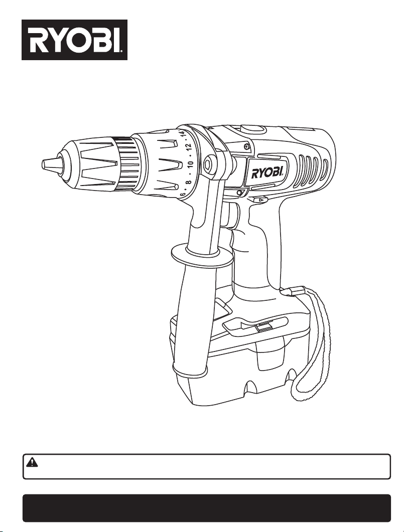
CORDLESS IMPACT DRILL-DRIVER
MODEL NO. CBI1442D / CBI1802D
This new cordless Impact drill-driver has been engineered and manufactured to Ryobi's high standard for dependability, ease of
operation, and operator safety.When properly cared for, the drill-driver will give you years of rugged, trouble-free performance.
WARNING: To reduce the risk of injury, the user must read and understand the operator's manual before
using this product.
Thank you for buying a Ry
obi product.
SAVE THIS MANUAL FOR FUTURE REFERENCE
Page 2
6
8
10
12
14
6
8
10
12
14
1 .
6
8
10
12
14
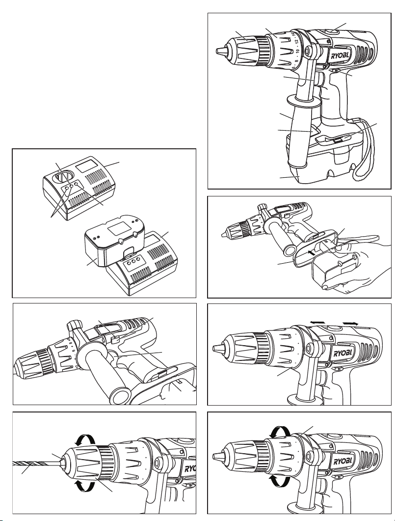
Fig. 5
Keyless chuck
2 .
Torque adjustment ring with mode selector
3 .
Two speed gear selector (HI-LO)
4 .
Bit storage area
5 .
Direction of rotation selector (forward/reverse)
6 .
Switch trigger
7.
Battery pack
8 .
Auxiliary handle
9 .
LCD battery capacity indicator
1
2
6
8
9
3
5
4
Green Light
Yellow and
Green Light
Chuck
Drill bit
jaws
Red Light
Battery
pack
Centre position
(lock)
Unlock
(release)
Lock
(tighter)
Battery
Charger
Chuck
sleeve
rotation selector
Battery
charger
Fig. 1
Direction of
Switch
trigger
Fig. 3
7
Battery
Port
To increase
torque
To decrease
torque
To increase
torque
Hi speed(2)
Adjusting ring
Battery
Pack Neck
Fig. 2
Lo speed(1)
Fig. 4
Fig. 6
Page 3
RULES FOR SAFE OPERATION
MEANING OF SAFETY SIGNS
Wear eye
.
protection
GENERAL SAFETY RULES
WARNING:
Read all instructions. Failure to follow all instructions
listed below may result in electric shock, fire and/or
serious injury. The term 'power tool' in all of the warnings
listed below refers to your mains operated (corded)
power tool
S
AVE THESE INSTRUCTIONS
WORK AREA
Keep work area clean and well lit. Cluttered and dark
areas invites accidents.
Do not operate power tools in explosive atmospheres,
such as in the presence of flammable liquids, gases,
or dust. Power tools create sparks which may ignite the
dust or fumes.
Keep children and bystanders away while operating
a power tool. Distractions can cause you to lose control.
ELE
Power tool plugs must match the outlet. Never modify
the plug in any way. Do not use any adaptor plugs
with earthed (grounded) power tools. Unmodified
plugs and matching outlets will reduce risk of electric
shock.
Avoid body contact with earthed or grounded surfaces
such as pipes, radiators, ranges and refrigerators.
There is an increased risk of electric shock if your body
is ea
Do
Water entering a power tool will increase the risk of
electric shock.
Do not abuse the cord. Never use the cord for carrying,
pulling or unplugging the power tool. Keep cord away
from heat, oil, sharp edges or moving parts. Damaged or
entangled cords increase the risk of electric shock.
When operating a power tool outdoor
cord suitable for outdoor use. Use of cord suitable of
outdoor use reduces the risk of electric shock.
PERSONAL SAFETY
Stay alert, watch what you are doing and use common
sense when operating a power tool. Do not use a
power tool while you are tired or under the influence
of drugs, alcohol or medication. A moment of inattention
while operating power tools may result in seriou
injury.
Use safety equipment. Always wear eye protection.
Safety equipment such as dusk mask, non-skid safety
shoes, hard hat, or hearing protection used for appropriate
conditions will reduce personal injuries.
Avoid accidental starting. Ensure the switch is in
the off position before plugging in. Carrying power
tools with your finger on the switch or plugging in power
tools that hav
or battery operated (cordless) power tool.
CTRICAL
rthed or grounded.
not expose power tools to rain or wet conditions.
e the switch on invites accidents.
SAFETY
Wear ear
protection.
Wear dust
mask.
s,
use an extension
s
personal
Remove any adjusting key or wrench before turning
the power tool on. A wrench or a key left attached to
a rotating part of the power tool may result in personal
injury.
Do not overreach. Keep proper footing and balance
at all times. This enable better control of the power
tool in unexpected situations.
Dress properly. Do not wear loose clothing or
jewellery. Keep your hair, clothing and gloves a
f
rom moving parts. Loose clothes, jewellery or long
hair can be caught in moving parts.
If devices are provided for the connection of dust
extraction and collection facilities, ensure these
are connected and properly use. Use of these devices
can reduce dust related hazards.
POWER TOOL USE AND CARE
Do not force the power tool. Use the correct power
tool for your application. The correct power t
do the job better and safer at the rate for which it was
designed.
Do not use the power tool if the switch does not
turn it on and off. Any power tool that can not be
controlled with the switch is dangerous and must be
repaired.
Disconnect the plug from the power source before
making any adjustments, changing accessories,
or storing the power tools. Such preventive safety
measures reduc
a
ccidentally.
Store idle power tools out of the reach of children
and do not allow persons unfamiliar with the power
tool or these instructions to operate the power
tool. P ower tools are dangerous in the ha nds of
untrained users.
Maintain power tools. Check for misalignment or
binding of moving parts, breakage of parts and
any other condition that may affect
operation. If damaged, have the power tool repaired
before use. Many accidents are caused by poorly
maintained power tools.
Keep cuttin g too ls sharp and clean. Pro perly
maintained cutting tools with sharp cutting edges are
less likely to bind and are easier to control.
Use the power tool, accessories and tool bits, etc.,
in accordance with these instructions and in the
manner inte
tool, taking into account the working conditions
and the work to be performed. Use of the power
tool for operations different from intended could result
in a hazardous situation.
BATTERY TOOL USE AND CARE
Ensure the switch is in the off positi on before
inserting battery pack. Inserting the battery pack
into power tools that have the switch on invites accidents
Recharge only with the charger specified by the
m
anufacturer. A charger that is suitable for one type
of battery pack may create a risk of fire when used
with another battery pack.
Use power tools only with specifically designated
batter y packs. Use of any other ba ttery packs may
create a risk of injury and fire.
Page 2
e the risk of starting the power tool
the
nded f
or the particular type of power
way
ool will
power tools
.
Page 4

RULES FOR SAFE OPERATION
When battery pack is not in use, keep it away from
other metal objects like paper clips, coins, keys,
nails, screws or other small metal objects that can
make a connection from one terminal to another.
Shorting the battery terminals together may cause burns
or a fire.
Under abusive conditions, liquid may be ejected
from the battery, avoid contact. If contact accidentally
occurs, flush with water. If liquid contact eyes,
a
dditionally seek medical help. Liquid ejected from
the battery may caused irritation or burns.
SERVICE
Have your power tool serviced by an authorised
service centre using only identica l replacement
parts. This will ensure that the safety of the power
tool is maintained.
OPERATION
CONTENTS OF BOX
14.4V/18.0V cordless hammer drill, 2 double-ended
bits, 2 battery packs, charger, auxiliary handle.
OPERATING INSTRUCTIONS
CHARGING THE BATTERY PACK (fig. 1)
The battery packs for this tool have been shipped in a
low charge condition to pr event possible problems.
You should, therefore, charge them prior to use.
Note: Batteries will not reach full charge the first time
they are charged. A
by recharging) for the item to fully charge. The battery
charger should only be used indoors.
Make sure power supply is normal house voltage,
240VoHs, 50Hg, AC only.
Place the battery pack into the charger as indicated.
Align raised rib on battery pack with groove in charger.
Press down on battery pack to make sure contacts
on battery pack engage properly with conta
When properly connected, the red light on charger will
turn on.
After normal usage, 1 hour of charging time is required
for the battery to be fully charged.
Note: Normally the red light on the charger will come
on, this indicates charge mode. If the green and yellow
lights come on, remove the battery pack, wait 1 minute
and reinsert battery pack in charger. If the green and
w lights continue to remain on an additional 15
yello
minutes,
the battery pack is damaged and will not accept
charge. A maximum charge time of 1-1 1/2 hours is
required to recharge a completely discharged battery.
The battery pack will become slightly warm to the touch
while charging. This is normal and does not indicate a problem.
Dot not place the charger in an area of extreme heat
or cold. It will work
When the batteries become fully charged, the green
l
ight on charger will turn on. Unplug the charger from
power supply and remove the battery pack.
several cycles (drilling followed
llow
cts in charger.
best at normal room temperature.
MAINTENANCE
Your power to
maintenace. There are no user serviceable parts in
our power tool.
y
Never use water or chemical cleaners to clean your
power tool. Wipe clean with a dry cloth.
Always store your power tool in a dry place.
Keep the motor ventilation slots clean.
If you see some sparks flashing in the ventilation slots,
this is normal and will not damage your power tool.
WORKING H
If your power tool becomes too hot, set the speed to
maximum and run no load for 2-3 minutes to cool the
motor.
Always use a magnetic bit holder when using short
screwdriver bits.
Where possible use a pilot hole before drilling a large
diameter hole.
LED FUNCTION OF CHARGER
Red Fast charging mode
Green and yellow Control charge or defective
Green Fully charged
TO INSTALL BATTERY PACK (fig. 2)
Lock the switch trigger by placing the direction of rotation
selector in the central position.
To install, insert battery pack neck into drill's battery
port, making sure the latches on each side snap into
place and battery pack is secure before beginning
operation.
To remove, locate latches on side of battery pack and
depress both sides to release battery pack from d
L
CD BATTERY CAPACITY INDICATOR
The display is for guidance only. Deviations are possible
for extreme applications. It will be turned on when the
button is pressed, and will be turned off when the button
is released.
Note : Indicator is for reference only and can vary
according to ambience and application. For the LCD
display, it so be read when you push the LCD button
and the drill is on; if
reflect actual battery capacity when you push the LCD
button.
SWITCH (fig. 3)
The drill is starte d and stopped by depr essing and
releasing the switch trigger.
Release the switch trigger to turn the drill OFF.
SWITCH LOCK
The switch trigger can be locked in the OFF position.
This helps to reduce the possibility of accidental starting
when not in use. To lock the sw
direction of rotation selector in the centre position.
Page 3
ol requires no additional lubrication or
INTS FOR Y
OUR DRILL
t
he drill is off, the display does not
itch t
rill.
rigger, place the
Page 5

OPERATION
DIRECTION OF ROTATION
The direction of rotation is controlled by the direction
of rotation selector located above the switch trigger.
With t he dr ill held in n ormal op erati ng posit ion, the
direction of rotation selector should be positioned to
the left for forward direction.
Direction is reversed when the selector is to the right of
the switch. when the selector is in the centre position,
the switch
RIABLE SPEED
VA
This tool has a variable speed switch that delivers
higher speed and torque with increased trigger pressure.
Speed is controlled by the amount of switch trigger
depression.
TWO-SPEED GEAR SELECTOR (fig. 4)
The drill has a two-speed gear train designed for drilling
or driving at LO (1) or HI (2) speeds. A slide switch is
located on top of the drill to select either LO (
(2) speed. When using the drill in the LO (1) speed
range, the speed will decrease and the drill will have
greater power and torque. When using the drill in the
HI (2) speed range, the speed will increase and the
drill will have less power and torque.
INSTALLING AND REMOVING BITS (fig. 5)
Lock the switch trigger by placing the direction of rotation
selector in the central position.
This will
Rotate the chuck sleeve to open or close the chuck
jaws to a point where the opening is slightly larger
than the bit size intended for use. Insert the drill bit
nto the chuck to the full length of the jaws. Tighten the
i
chuck jaws on the drill bit by grasping the drill with one
hand, while rotating the chuck sleeve with the other
hand. To loosen the bit, g
one hand, while rotating the chuck sleeve with the
other hand.
TORQUE ADUSTMENT (fig. 6)
The torque is adjusted by rotating the torque adjustment
ring. The torque is greater when the torque adjustment
ring is set on a higher setting. The torque is less when
the torque adjustment ring is set on a lower setting.
Screwdriving/drilling
Gear level 1 (LO) suits for small
G
The torque is set by means of an adjustment ring.
The contact presusure on the screw has no influence
on the torque. Screwdriving can be carried out from
settings 1-23.
Impact drilling
Turn torque setting to the 'impact drilling' symbol.
DRILLING
When drilling hard smooth surfaces, use a centre punch
to mark the desired hole location.
drill bit from slipping off centre as the hole is started.
Hold the tool firmly and place the tip of the bit at the
point to be drilled. Depress the switch trigger to start
the tool. Move the drill bit into the workpiece, applying
only enough pressure to keep the bit cutting. Do not
force or apply side pressure to elongate a hole.
trigger is locked.
1) o
lock the switch trigger in the OFF position.
rasp and hold the drill with
screws/drilling
ear level 2 (HI) suits for large screws/drilling
This will prevent the
WOOD DRILLING
For maximum performance, use high s
for wood drilling.
Turn the torque adjustment ring on the drill to desired
torque setting.
Begin drilling at a very low speed to prevent the bit
from slipping off the starting point.
Increase the speed as the drill bit bites into the material.
When drilling through holes, place a block of wood
behind the workpiece to prevent ragged or splintered
edges on the back side of the hole.
ETA
L DRILLING
M
For maximum performance, use high speed steel bits
for metal or steel drilling.
Turn the torque adjustment ring on the drill to desired
torque setting.
Begin drilling at a very low speed to prevent the bit
r HI
from slipping off the starting point.
Maintain a speed and pressure which allows cutting
without overheating the bit.
Applying too much pressure will:
• Overheat the drill
• Wear the bear
• Bend or burn bits
• Produce off-center or irregular shaped holes
When drilling large holes in metal, it is recommended
that you drill with a small bit at first, then finish with a
larger bit. Also, lubricate the bit with oil to improve
drilling action and increase bit life.
MASONRY DRILLING
For maximum performance use carbide-tipped masonry
impact bits when drilling holes in brick, tile, concret
e
tc.
Turn the mode selector on the drill to hammer mode.
Rotate the torque selector to drill position.
Apply light pressure and medium speed for best results
in brick.
Apply additiona l pressure and high speed for hard
materials such as concrete.
When drilling holes in tile, practice on a scrap piece to
determine the best speed and pressure.
DISPOSAL OF AN EXHAUSTED BATTERY
To preserve natural resourc
of the battery properly.
This product contains nickel-cadmium batteries. Consult
your local waste authority for information regarding
available recycling and/or disposal options.
PERPARING BATTERY PACK FOR RECYCLING
After removing, cover the battery pack’s terminal with
heavy-duty adhesive tape.
Do not attempt to destroy or take the battery pack
apart or remove any of its
both terminals with metal objects or body parts or a
short circuit may result. Keep away from children. Failure
to comply with these warnings could result in fire and/or
serious injury.
ings
es,
please recycle or dispose
c
omponents. Do not touch
peed steel bits
e,
Page 4
Page 6

SPECIFICATIONS
Drill voltage
Switch
Chuck
No load speed:
Drill mode
Impact mode
Power supply
Torque
No. of Power Pack
Weight
Charger input
Charging time
Battery pack
Charger
14.4V
variable, forward & reverse
13mm keyless (steel max. Ø10mm)
0-350 / 0-1300 /min
0-4550 / 0-16900 bpm
12 x 1.2V Ni-Cd 1500mAh
32Nm
2pcs
2.1 kg (with battery)
AC 240V 50Hz
1 hour (approx.)
130262022
2601050
MAINTENANCE
WARNING:
When servicing, use only identical replacement parts.
Use o f an y other part may create a hazard or cau se
product damage.
Avoid using solvents when cleaning plastic parts.
Most plastics are susceptible to damage from various
types of commercial solvents and may be damaged by
their use. Use clean cloths to remove dirt, dust, oil,
grease, etc.
18.0 V
variable, forward & reverse
13mm keyless (steel max. Ø10mm)
0-400 / 0-1400 /min
0-5200 / 0-18200 bpm
15 x 1.2V Ni-Cd 1500mAh
35Nm
2pcs
2.4 kg (with battery)
AC 240V 50Hz
1 hour (approx.)
130262021
2601038
WARNING:
Do not attempt to modify this tool or create accessories
not rec ommen ded for us e wi th t his to ol. Any such
alteration or modification is misuse and could result
in a hazardous condition leading to possible serious
p
ersonal injury.
.
WARNING:
Do not at any time let brake fluids, gasoline, petroleum-
ased products, penetrating oils, etc. come in contact
b
w
ith plastic parts. They contain chemicals that can
damage, weaken or destroy plastic.
Do not abuse power tools. Abusive practices can damage
tool as well as workpiece.
Page 5
Page 7

RYOBI HELPLINE
has no
wear and tear.
The Company accepts no additional liability pursuant to
this g u a r a n t e e f o r th e c o s t s o f trav e l l i n g o r
transportation of the Product or parts to and from the
service dealer or agent - such costs are not included
his guarantee.
t
Certain legislation, including the Trade Practices Act,
1974 (as amended) and other state and territorial laws
give rights to the buyer and impose liability on the seller in
certain circumstances. Nothing herein shall have the effect
of excluding, restricting or modifying any condition,
guarantee, right or liability imposed, to the extent only
th a t s u c h e x clu s i on, res t r ict i on o r modification
w
ould render any term herein void.
RYOBI TECHNOLOGIES AUSTRALIA PTY. LTD.
SYDNEY: 359-361 Horsley Road, Milperra, N.S.W. 2214.
Tel: (02) 9792 9800 - Fax: 1800 807 993 - www.ryobi.com.au
Tel : (03) 9764 8656
A.B.N. 98 002 277 509
Contact during normal business hours.
HOBART: All enquiries Tel : 1300 361 505
ADELAIDE: All enquiries Tel : 1300 361 505
PERTH: 33-35 Sorbonne Cres. Canning Vale, W.A. 6155
RYOBI NEW ZEALAND PTY. LTD.
AUCKLAND: 27 Clemow Drive, Mt Wellington, N.Z.
 Loading...