

Page 1
OPERATOR’S MANUAL
LETTER TEMPLATE SET AND
GUIDE BUSHINGS
A25RE02
Your routing kit has been engineered and manufactured to our high standard for dependability, ease of operation, and
operator safety. When properly cared for, it will give you years of rugged, trouble-free performance.
WARNING: To reduce the risk of injury, the user must read and understand the operator's manual before using
this product.
Thank you for your purchase.
SAVE THIS MANUAL FOR FUTURE REFERENCE
Page 2
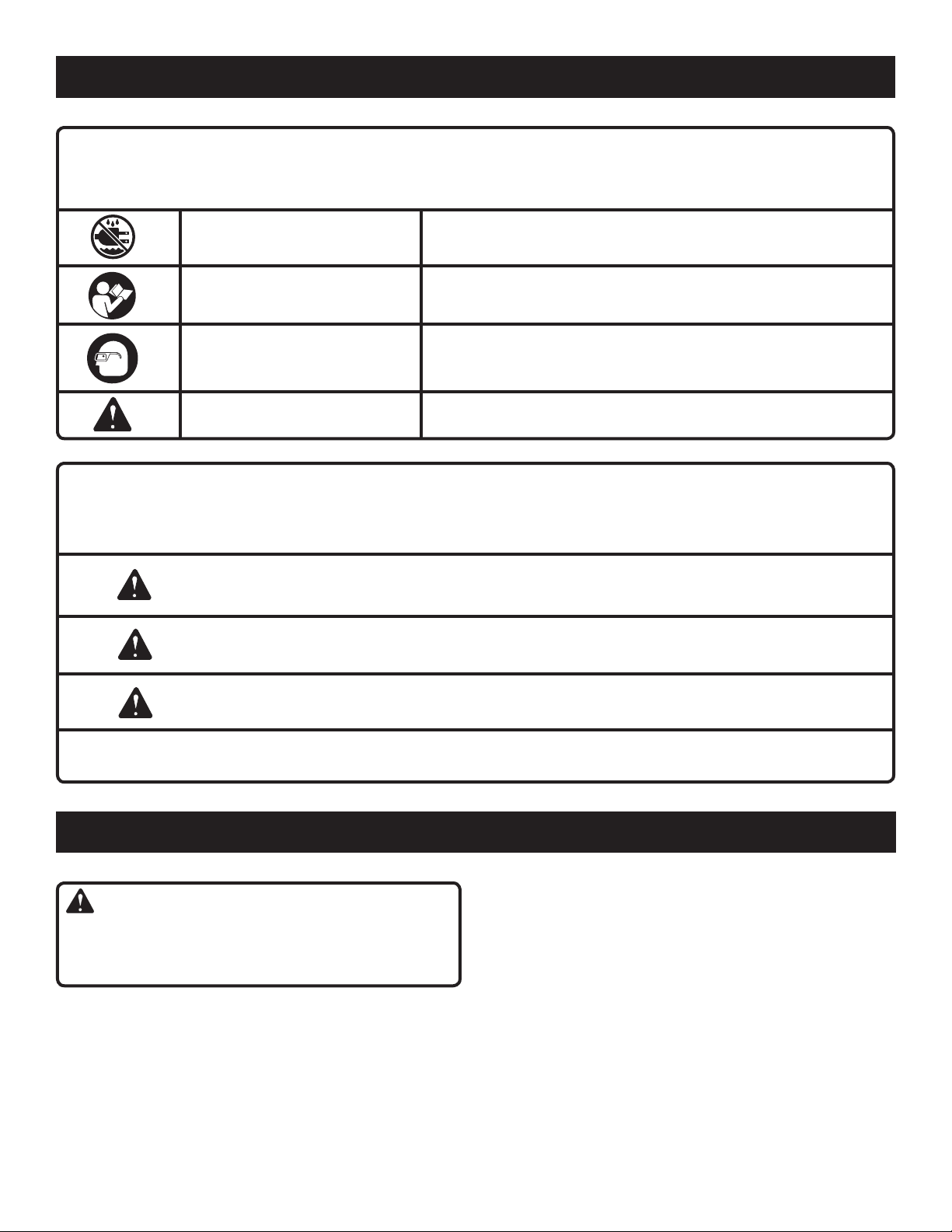
SYMBOLS
Some of the following symbols may be used on this tool. Please study them and learn their meaning. Proper interpretation
of these symbols will allow you to operate the tool better and safer.
SYMBOL NAME DESIGNATION/EXPLANATION
Wet Conditions Alert
Read The Operator’s Manual
Eye Protection
Safety Alert
The following signal words and meanings are intended to explain the levels of risk associated with this
product.
SYMBOL SIGNAL MEANING
DANGER:
WARNING:
Indicates an imminently hazardous situation, which, if not avoided, will
result in death or serious injury.
Indicates a potentially hazardous situation, which, if not avoided, could
result in death or serious injury.
Do not expose to rain or use in damp locations.
To reduce the risk of injury, user must read and understand
operator’s manual before using this product.
Always wear safety goggles or safety glasses with side shields,
or a full face shield when operating this product.
Precautions that involve your safety.
CAUTION:
CAUTION:
Indicates a potentially hazardous situation, which, if not avoided, may
result in minor or moderate injury.
(Without Safety Alert Symbol) Indicates a situation that may result in
property damage.
ASSEMBLY
WARNING:
READ AND UNDERSTAND ALL INSTRUCTIONS. Fail-
ure to follow all instructions listed below, may result in
electric shock, fire and/or serious personal injury.
Safe operation of this accessory requires that you read and
understand this operator’s manual, the operator’s manual
for the tool with which this product is intended to be used,
and all labels affixed to the tool.
SAVE THESE INSTRUCTIONS
READ ALL INSTRUCTIONS
n KNOW YOUR ACCESSORY. Read the operator’s manual
carefully. Learn the applications and limitations as well
as the specific potential hazards related to this tool.
2 3
Page 3
ASSEMBLY
UNPACKING
This product requires assembly.
n Carefully remove accessories from the box. Make sure
that all items listed in the packing list are included.
n Inspect the accessories carefully to make sure no break-
age or damage occurred during shipping.
n Do not discard the packing material until you have care-
fully inspected and satisfactorily operated the tool.
n If any parts are damaged or missing, please call
1-800-525-2579 for assistance.
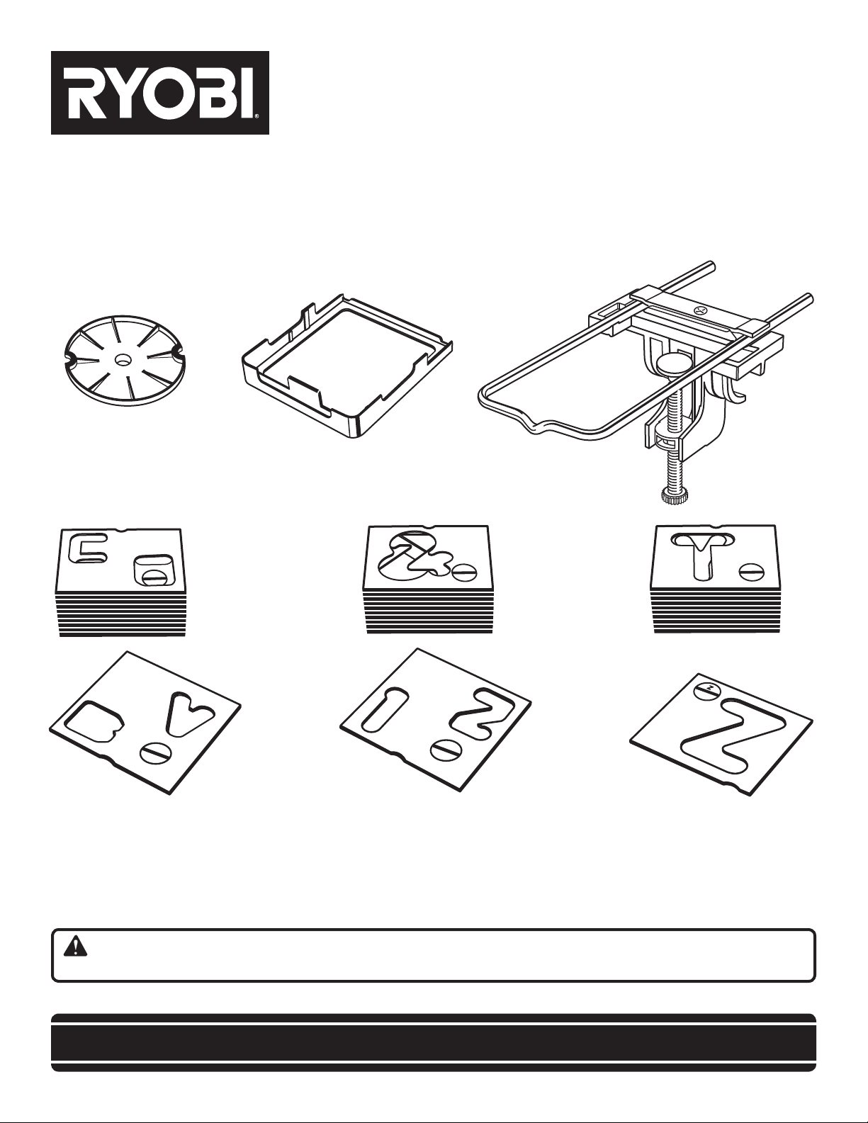
PACKING LIST
Router Bit Set (15)
Router Lettering Template Set
2-1/2 in. Letter and Number Template Set
1-1/2 in. Letter and Number Template Set
Hardware for Mounting Letter Template Set
Guide Bushings (5) with Screws (2)
DVD
CD
Non-skid Mat
Tool Bag
Operator’s Manual
U-BOLT CLAMP
U-BOLT
FLAT HEAD
SCREW
COUNTERSINK
SQUARE
NUT
MOUNTING BRACKET
Fig. 1
WARNING:
If any parts are missing do not operate this product until
the missing parts are replaced. Failure to do so could
result in possible serious personal injury.
WARNING:
Do not attempt to modify these accessories. Any such
alteration or modification is misuse and could result in a
hazardous condition leading to possible serious personal
injury.
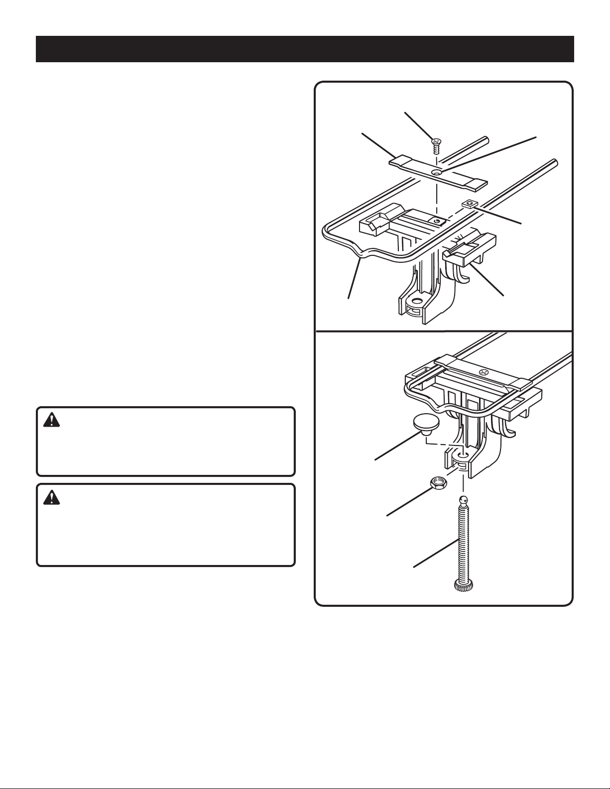
ASSEMBLING THE U-BOLT, M O U N T IN G
BRACKET, AND CLAMP SCREW
See Figures 1 - 2.
n Lay the U-bolt clamp on the mounting bracket with the
countersink up, away from the mounting bracket.
n Fit the square nut under the bracket and insert the flat
head screw in the countersink.
n Slide the U-bolt under the clamp and tighten the flat head
screw.
SWIVEL
BUTTON
HEX NUT
CLAMP SCREW
Fig. 2
n Insert the hex nut into the slot located in the lower part
of the mounting bracket.
n Thread the clamp screw through the nut with the ball end
pointing up.
n Push the swivel button on the ball end of the clamp
screw.
Page 4

OPERATION
WARNING:
Do not allow familiarity with tools to make you careless. Remember that a careless fraction of a second is
sufficient to inflict serious injury.
WARNING:
Always wear safety goggles or safety glasses with side
shields when operating tools. Failure to do so could result in objects being thrown into your eyes, resulting in
possible serious injury.
WARNING:
Failure to unplug your router could result in accidental
starting causing serious injury.
APPLICATIONS
You may use this accessory for the purposes listed below:
n Routing letters and numbers with templates
n Routing curves and complex shapes with the use of
templates
SETTING UP THE TEMPLATE
See Figures 3 - 4.
n Lay the workpiece on a workbench and place mount-
ing bracket on the workpiece with the U-bolt over the
workpiece and the clamp screw under the workbench.
NOTE: Clamp screw will hold workpiece to workbench
while routing if total thickness of both is 1-3/4 in. or less.
When thickness of workpiece and workbench exceeds
1-3/4 in., use a clamp to hold workpiece to workbench
and the clamp screw to hold mounting bracket to
workpiece.
n Lay letter template on top of U-bolt, leaving room between
cross member of U-bolt and end of template for letter
frame.
n Slip letter frame over template and U-bolt until legs
are against workpiece. Be sure that letter frame is over
cross member of U-bolt and template is up inside letter
frame.
n Loosen flat head screw, and adjust U-bolt to position
template in desired location over workpiece. Retighten.
MOUNTING
BRACKET
LETTER
TEMPLATE
CROSS
MEMBER
FLAT HEAD
SCREW
WORKPIECE
CLAMP SCREW
U-BOLT
WORKBENCH
Fig. 3
LETTER
FRAME
Fig. 4
4 5
Page 5

OPERATION
ROUTING WITH GUIDE BUSHING
You can accurately duplicate curves and complex shapes by
fitting your router with a template guide bushing that extends
below the subbase. The router bit passes through the guide
bushing. The guide bushing then rides against a template.
INSTALLING TEMPLATE GUIDE BUSHING
See Figures 5 - 7.
n �Unplug your router.
n �Place router upside down on workbench.
n �Place template guide bushing in recessed portion of
router base.
n �Align the cutouts in guide bushing with threaded holes in
base.
n �Secure guide bushing to router base with screws pro-
vided.
n �Tighten screws securely.
WARNING:
Failure to tighten screws could cause bit to come in contact with bushing, resulting in serious injury.
COLLAR
CUTOUTS
HOLES
IN BASE
ROUTER
BIT
TEMPLATE GUIDE
BUSHING
SCREW
RECESS IN
BASE
SUBBASE
Fig. 5
ROUTER BASE
When routing with template guide bushings it is necessary
to allow for size differences between the cutting edge of the
bit and the face of the guide bushing collar. When making
templates, always allow for this size difference.
NOTE: Special Instructions for use with routers R181D,
R181FB, R181PF, R1801M, and RE1802M.
n Unplug your router.
n Follow the previous steps to secure the guide bushing to
subbase.
n Tighten screws securely.
n Loosen the 4 subbase screws that secure the subbase
to the router base.
n Set bit to desired depth and lock depth lock.
n Adjust subbase so that the end of the bit is centered in
collar of the bushing.
n Tighten the 4 subbase screws securely.
WORKPIECE
SUBBASE
SIZE DIFFERENCE
SUBBASE SCREW
TEMPLATE
GUIDE
BUSHING
TEMPLATE
GUIDE
ROUTER
BIT
TEMPLATE GUIDE
BUSHING COLLAR
Fig. 6
BIT
SUBBASE
DEPTH LOCK LEVER
Fig. 7
Page 6

13
32
7
1
532
16
11
32
5
16
3
8
OPERATION
1
3
3
2
7
153
2
1
6
1
1
3
2
5
1
6
3
8
ROUTING WITH THE TEMPLATE
See figures 8 - 10.
NOTE: Refer to the Operator’s Manual that accompanied
your router for instructions on how to correctly install and
remove router bits.
Before making a cut in the workpiece, rout the first letter
in scrap material to get a feel for guiding the router around
the template.
n With bit installed in router, set bit to desired depth of
cut.
n Place router guide bushing into letter opening.
NOTE: Template guide bushing must be in contact with
letter template with bit slightly above workpiece when
router is started.
n Turn router on and lower into wood until router base rests
on letter frame.
n Follow opening with slight pressure to outside of letter
until you have routed completely around the letter and
returned to where you started.
n Turn router off and wait until bit comes to a complete
stop before lifting router off letter frame.
n Loosen clamp screw.
n Slide mounting bracket to the right until left side of letter
frame lines up with edge of routed letter just completed.
(This gives you uniform spacing between each letter.)
n Remove template of letter just routed and replace with
next template to be used.
n Continue process until project is complete.
GUIDE
BUSHING
BIT
LETTER
TEMPLATE
CLAMP SCREW
ROUTER BASE
LETTER
FRAME
WORKPIECE
Fig. 8
HELPFUL HINTS
n When using the small set of letter templates, always posi-
tion the letter to be routed in the lower left hand corner
of the letter frame.
n Redwood is a good sign material. It is easy to rout and
has a long outdoor life.
n Finish your sign quickly and easily by painting the entire
top surface of the finished sign with fast drying paint. (Us-
ing paint in aerosol cans is helpful.) Sand the top surface
of the sign leaving the paint in routed letters. The non-skid
mat is useful for holding the sign in place.
n Vertical signs can be routed by turning the letter template
90˚ in the letter frame.
n Letters can be routed close to the edge of a sign by turn-
ing workpiece around. Turn letter templates around and
locate letters close to the far edge of the workpiece.
WARNING:
Some workpieces may not be securely held with the
non-skid mat. Always assure your workpiece is securely
held in place by the mat or clamps before beginning any
cutting operation.
TEMPLATE GUIDE
BUSHING COLLAR
LETTER
TEMPLATE
BIT
Fig. 9
Fig. 10
6 7
Page 7

NOTES
Page 8

OPERATOR’S MANUAL
LETTER TEMPLATE SET AND
GUIDE BUSHINGS
A25RE02
• SERVICE
Now that you have purchased your tool, should a need ever exist for repair parts or
service, simply contact your nearest Ryobi Authorized Service Center. Be sure to provide
all pertinent facts when you call or visit. Please call 1-800-525-2579 for your nearest Ryobi
Authorized Service Center. You can also check our web site at www.ryobitools.com for a
complete list of Authorized Service Centers.
• HOW TO ORDER REPAIR PARTS
When ordering repair parts, always give the following information:
• MODEL NUMBER
• SERIAL NUMBER
Ryobi® is a registered trademark of Ryobi® Limited used under license.
A25RE02
983000-814
8-05
RYOBI TECHNOLOGIES, INC.
1428 Pearman Dairy Road, Anderson, SC 29625
Post Office Box 1207, Anderson, SC 29622-1207
Phone 1-800-525-2579
www.ryobitools.com
8
 Loading...