

Page 1
RBC30SESB / RBC30SBSB
FR
COUPE-BORDURES / DÉBROUSSAILLEUSE MANUEL D’UTILISATION 1
EN
STRING TRIMMER / BRUSHCUTTER USER’S MANUAL 13
DE
KANTENSCHNEIDER / FREISCHNEIDEGERÄT BEDIENUNGSANLEITUNG 23
ES
RECORTADORA DE HILO / CORTADORA DE MALEZA MANUAL DE UTILIZACIÓN 35
IT
TAGLIABORDI / DECESPUGLIATORE MANUALE D’USO 46
PT
APARADOR DE RELVA / CORTA-SEBES MANUAL DE UTILIZAÇÃO 58
NL
GRASTRIMMER / BOSMAAIER GEBRUIKERSHANDLEIDING 70
SV
TRIMMER / RÖJSÅG INSTRUKTIONSBOK 82
DA
TRÅDTRIMMER / BUSKRYDDER BRUGERVEJLEDNING 92
NO
TRÅDTRIMMER / KRATTRYDDER BRUKSANVISNING 102
FI
SIIMALEIKKURI/RUOHORAIVURI KÄYTTÄJÄN KÄSIKIRJA 112
HU
SZEGÉLYVÁGÓ / BOZÓTVÁGÓ MOTOROS KASZA HASZNÁLATI ÚTMUTATÓ 122
CS
STRUNOVÁ SEKAČKA / KŘOVINOŘEZ NÁVOD K OBSLUZE 134
RU
ТРИММЕР / КУСТОРЕЗА РУКОВОДСТВО ПО ЗКСПЛУАТАЦИИ 144
RO
TRIMMER / APARAT PENTRU TUNS TUFIŞURI MANUAL DE UTILIZARE 15
PL
PODKASZARKA DO OBRZEŻY/ŚCINACZ KRZEWÓW INSTRUKCJA OBSŁUGI 16
SL
KOSILNICA Z NITKO / OBREZOVALNIK GRMOVJA UPORABNIŠKI PRIROČNIK 17
HR
©I©A»/REZA»ICA KORISNI»KI PRIRU»NIK 18
ET
TRIMMER-VÕSALÕIKUR KASUTAJAJUHEND 197
LT
ŽOLIAPJOVĖ / KRŪMAPJOVĖ NAUDOJIMO VADOVAS 207
LV
ROKAS PĻAUJMAŠĪNA / KRŪMGRIEZIS LIETOTĀJA ROKASGRĀMATA 217
SK
STRUNOVÁ KOSAČKA/KROVINOREZ NÁVOD NA POUŽITIE 227
BG
ТРИМЕР / ТРИМЕР ЗА РАЗЧИСТВАНЕ РЪКОВОДСТВО ЗА УПОТРЕБА 237
RBC30SESB
Important! It is essential that you read the instructions in this manual before mounting and operating
this machine.
RBC30SBSB
Page 2

VL
ȼɚɠɧɨ
6XEMHFWWRWHFKQLFDOPRGLILFDWLRQV6RXVUpVHUYHGHPRGLILFDWLRQVWHFKQLTXHV7HFKQLVFKHbQGHUXQJHQYRUEHKDOWHQ
%DMRUHVHUYDGHPRGLILFDFLRQHVWpFQLFDV&RQULVHUYDGLHYHQWXDOLPRGLILFKHWHFQLFKH7HFKQLVFKHZLM]LJLQJHQYRRUEHKRXGHQ
&RPUHVHUYDGHPRGLILFDo}HVWpFQLFDV0HGIRUEHKROGIRUWHNQLVNHQGULQJHU0HGI|UEHKnOOI|UWHNQLVNDlQGULQJDU
7HNQLVHWPXXWRNVHWYDUDWDDQ0HGIRUEHKROGRPWHNQLVNHHQGULQJHUɦɨɝɭɬɛɵɬɶɜɧɟɫɟɧɵɬɟɯɧɢɱɟɫɤɢɟɢɡɦɟɧɟɧɢɹ
=]DVWU]HĪHQLHPPRG\ILNDFMLWHFKQLF]Q\FK=PČQ\WHFKQLFNêFK~GDMĤY\KUD]HQ\$PĦV]DNLPyGRVtWiVMRJiWIHQQWDUWMXN
3DVLOLHNDQWWHLVĊGDU\WLWHFKQLQLXVSDNHLWLPXV7HKQLOLVHGPXXGDWXVHGY}LPDOLNXG3RGORQRWHKQLsNLPSURPMHQDPD
7HKQLþQHVSUHPHPEHGRSXãþHQH3UiYRQDWHFKQLFNp]PHQ\MHY\KUDGHQpɉɨɞɥɟɠɢɧɚɬɟɯɧɢɱɟɫɤɢɦɨɞɢɮɢɤɚɰɢɢ
Ɉɬɢɡɤɥɸɱɢɬɟɥɧɚɜɚɠɧɨɫɬɟɞɚɩɪɨɱɟɬɟɬɟɢɧɫɬɪɭɤɰɢɢɬɟɜɬɨɜɚɪɴɤɨɜɨɞɫɬɜɨɩɪɟɞɢɞɚɛɨɪɚɜɢɬɟɫ
ɬɚɡɢɦɚɲɢɧɚ
6XEUH]HUYDPRGLILFDĠLLORUWHKQLFH3DWXUDPWLHVƯEDVPDLQƯWWHKQLVNRVUDNVWXUOLHOXPXV
Page 3

EN Some regions have regulations that restrict the use of the product to some operations. Check with your local authority
for advice.
FR La législation de certaines régions restreint l'utilisation du produit à certaines opérations. Contactez les autorités
locales pour de plus amples informations.
DE In einigen Regionen können Vorschriften die Benutzung dieses Produktes auf einige Tätigkeiten beschränken. Lassen
Sie sich von Ihrer örtlichen Behörde beraten.
ES Algunas regiones tienen normativas que restringen el uso del producto para algunas operaciones. Consulte con sus
autoridades locales.
IT In alcune regioni norme speci¿ che limitano l'utilizzo del prodotto ad alcune operazioni. Controllare con le autorità locali
per avere ulteriori informazioni a riguardo.
NL In enkele streken gelden regels die het gebruik van het product tot enkele handelingen beperken. Raadpleeg uw
gemeentebestuur voor advies.
PT Algumas regiões têm normas que restringem o uso do produto para algumas operações. Consulte as autoridades
locais.
DA Nogle områder har regler, som begrænser brugen af produktet til visse formål. Forhør dig hos de lokale myndigheder.
SV En del regioner har regelverk som begränsar produktens användning till vissa funktioner. Kontrollera med lokala
myndigheter.
FI Joillain alueilla vallitsee säädöksiä, jotka rajoittavat tämän tuotteen käyttöä joissain toiminnoissa. Pyydä paikallisilta
viranomaisilta neuvoa.
NO Visse regioner har forskrifter som begrenser bruken av produktet til de¿ nerte operasjoner. Sjekk hos lokale myndigheter
for råd.
RU ȼ ɧɟɤɨɬɨɪɵɯ ɪɟɝɢɨɧɚɯ ɫɭɳɟɫɬɜɭɸɬ ɨɝɪɚɧɢɱɟɧɢɹ ɧɚ ɢɫɩɨɥɶɡɨɜɚɧɢɟ ɧɟɤɨɬɨɪɵɯ ɨɩɟɪɚɰɢɣ ɫ ɞɚɧɧɵɦ ɭɫɬɪɨɣɫɬɜɨɦ.
Ɉɛɪɚɳɚɣɬɟɫɶ ɡɚ ɢɧɮɨɪɦɚɰɢɟɣ ɜ ɦɟɫɬɧɵɟ ɨɪɝɚɧɵ ɜɥɚɫɬɢ.
PL W niektórych regionach obowiązują przepisy ograniczające uĪywanie produktu w przypadku okreĞlonych dziaáaĔ.
Informacje na ten temat moĪna uzyskaü w lokalnych urzĊdach.
CS Místní pĜedpisy mohou omezovat použití výrobku. OvČĜte si u svého orgánu místní správy toto naĜízení.
HU Egyes régiókban olyan elĘírások érvényesek, amelyek korlátozzák a termék bizonyos mĦveletekre való használatát.
További információért forduljon a helyi önkormányzathoz.
RO Unele regiuni au reglementări care restricĠionează utilizarea produsului la unele operaĠiuni. CereĠi sfatul autorităĠii
locale.
LV Dažos reƧionos pastƗv noteikumi, kas ierobežo darbƯbas, kurƗm produkts ir izmantojams. Lai uzzinƗtu vairƗk,
konsultƝjieties ar vietƝjƗm iestƗdƝm.
LT Kai kuriuose regionuose šio gaminio naudojimą tam tikriems darbams apriboja galiojantys Ƴstatymai. Dơl patarimǐ
kreipkitơs Ƴ vietinơs valdžios instituciją.
ET Mõnedes piirkondades on seadused, mis piiravad toote kasutamist teatud tööde tegemiseks. Lisateavet saate
kohalikust omavalitsusest.
HR Neke regije imaju pravila koja ograniþavaju korištenje proizvoda za neke radove. Provjerite kod lokalnih tijela za savjet.
SL V nekaterih regijah predpisi omejujejo uporabo izdelka na doloþene namene. Za nasvet se obrnite na lokalne oblasti.
SK Niektoré regióny majú nariadenia, ktoré obmedzujú použitie produktu na urþité operácie. Poraćte sa s miestnym
úradom.
BG ȼ ɧɹɤɨɢ ɪɟɝɢɨɧɢ ɢɦɚ ɪɚɡɩɨɪɟɞɛɢ, ɨɝɪɚɧɢɱɚɜɚɳɢ ɢɡɩɨɥɡɜɚɧɟɬɨ ɧɚ ɩɪɨɞɭɤɬɚ ɞɨ ɨɩɪɟɞɟɥɟɧɢ ɨɩɟɪɚɰɢɢ. ɉɨɢɫɤɚɣɬɟ
ɫɴɜɟɬ ɨɬ ɦɟɫɬɧɢɬɟ ɜɥɚɫɬɢ.
Page 4

Assembly
EN
ATTACHING THE HANDLE
(Fig. 2a)
■ Remove the bolts and bracket from the front handle.
■ Place the handle bar.
NOTE: The throttle trigger must be mounted to the operator's
right side.
■ Replace the bolts and bracket.
■ Adjust the handle bar for best operator control and comfort.
■ Tighten the two bolts securely with the combination wrench
supplied.
ATTACHING THE BLADE GUARD AND GRASS
DEFLECTOR
Blade guard
(Fig. 2b)
■ To attach the blade deflector to the mounting bracket, align the
screw holes on the blade deflector to the bolts on the mounting
bracket.
■ Using the combination wrench supplied, tighten the two bolts
securely.
WARNING:
– The blade deflector should remain fitted to the product at
all times.
– When using the line trimmer bump head, the grass deflector
must be attached to the blade guard.
– When using the brushcutter blade, the grass deflector must
be removed from the blade guard.
Grass defl ector
(Fig 2b)
■ To attach the grass deflector to the blade deflector, align the 3
screws on the grass deflector to the screw holes on the blade
deflector.
■ Using the combination wrench supplied, tighten the two bolts
securely.
NOTE: When using the line trimmer bump head, the grass
deflector must be attached to the blade guard.
INSTALLING THE REELEASY™ LINE TRIMMER HEAD
(Fig. 2c)
■ Stop the engine and disconnect the spark plug wire.
■ Remove the bump head from the drive connector.
■ Open the ReelEasy™ Line Trimmer Head by depressing the
latches on each side.
NOTE: The contents of the line trimmer head are spring loaded,
so keep your other hand over the line trimmer head cover while
depressing the latches.
■ Remove the line trimmer head cover, bump knob, and line spool
and set aside.
■ Place the cutting head housing on the drive shaft.
■ Make sure the housing is fully seated.
■ Install the hex bolt to secure the line trimmer head to the drive
shaft.
■ Tighten by using the hex-shaped opening on the inside of the
bump knob.
NOTE: Only use the bump knob to tighten the bolt. The use of
other tools may allow over tightening of the bolt, which could
damage the line trimmer head.
■ Reinstall the bump head spring into the line trimmer head and
push down to seat.
■ Reinstall the line spool.
■ For the curved shaft attachment with the ReelEasy™ cutting
head the spool should be placed so “For curved shaft” is visible
on the line spool.
■ Replace the bump knob by inserting it into the centre of the
line spool.
■ Replace the line trimmer head cover, aligning latches with
openings in the line trimmer head.
■ Press cover and line trimmer head together until both latches
snap into openings securely.
■ Install line as described in the next section of this manual.
INSTALLING LINE IN REELEASY™ LINE TRIMMER
HEAD
(Fig. 2c)
■ Use a 2.4 mm diameter monofilament string.
■ Stop the engine and disconnect the spark plug wire.
■ Cut one piece of string approximately 6 m in length.
■ Rotate the knob on the string head until the line on knob aligns
with the arrows on the top of string head.
■ Insert one end of the string into the eyelet located on the side of
the string head and push until string comes out through eyelet
on the other side.
■ Continue to push string through the string head until the middle
section of the string is inside the string head and string outside
the string head is evenly divided on each side.
■ Rotate the knob on the line trimmer head to wind the line.
■ If using a curved shaft attachment, the knob should be rotated
counterclockwise.
■ Wind the string until approximately 20 cm remains protruding
from the string head.
■ Replace the spark plug boot.
ATTACHING THE SHOULDER STRAP
(Fig. 2d)
■ Connect the latch on the shoulder strap to the strap hanger.
■ Adjust the strap hanger to a comfortable position.
NOTE: Always use the shoulder strap/harness with your unit.
CONVERTING FROM STRING TRIMMER TO
BRUSHCUTTER
(Fig. 2e)
Page 5

EN
WARNING: Always stop the engine and disconnect the spark plug
wire from the spark plug.
Removing the bump head
■ Place the holding pin through the slot in the upper flange
washer and the hole in the gear head.
■ Unlock the spool retainer as shown and remove the spool.
■ Remove the bump head from the drive connector.
■ Place the holding pin through the slot in the upper flange
washer and the hole in the gear head.
■ Turn the connector clockwise to remove.
■ Remove the washer.
WARNING: When using the brushcutter blade, the grass defl ector
must be removed from the blade guard.
Installing the blade
■ Place the upper flange washer over the gear shaft with the
hollow side towards the gear head.
■ Centre the blade on the upper flange, making sure the blade
sits flat.
■ Install the cupped washer with the raised centre away from the
blade.
■ Place the holding pin through the slot in the upper flange
washer and the hole in the gear head.
■ Replace the blade nut and tighten securely by turning clockwise.
Assembly
CONVERTING FROM BRUSHCUTTER TO STRING
TRIMMER
WARNING: Always stop the engine and disconnect the spark plug
wire from the spark plug.
Removing the blade
■ Place the holding pin through the slot in the upper flange
washer and the hole in the gear head.
■ Remove the blade nut, washers, and blade.
■ Attach the grass deflector to the blade deflector; align the 3
screws on the grass deflector to the screw holes on the blade
deflector.
■ Using the combination wrench supplied, tighten the two bolts
securely.
WARNING: When using the line trimmer bump head, the grass
defl ector must be attached to the blade guard.
Installing the bump head
■ Place the upper flange washer over the gear shaft with the
hollow side towards the gear head.
■ Place the holding pin through the slot in the upper flange
washer and the hole in the gear head.
■ Place the bump head on the drive connector.
■ Tighten securely with wrench.
Page 6

English (Original instructions)
SYMBOLS
Important: Some of the following symbols may be used on your tool. Please study them and learn their meaning.
Proper interpretation of these symbols will allow you to operate the tool better and more safely.
SYMBOLS EXPLANATION
Indicates danger, warning or caution. it means attention!!!
Your safety is involved.
Your manual contains special messages to bring attention to potential safety concerns as well as
operating and servicing information. Please read all the information carefully to ensure satisfaction
and safe use.
Wear eye, hearing and head protection when operating this equipment.
Danger of Ricochet. Keep all bystanders, especially children and pets, at least 15m from the
operating area.
Tri-Arc blade is appropriate for this unit and is suited for cutting pulpy weeds and vines.
This unit is not intended for use with a toothed saw type blade.
Rotational direction and maximum speed of the shaft for the cutting attachment.
Wear non-slip safety footwear when using this equipment.
Wear non-slip, heavy-duty gloves.
Do not smoke when mixing fuel or filling fuel tank.
Use unleaded petrol intended for motor vehicle use with an octane rating of 91([R+M]/2) or higher.
Use 2-stroke lubricant for air cooled engines.
Mix the fuel mix thoroughly and also each time before refuelling.
CE Conformity s to all regulatory standards in the country in the EU where the product is
purchased.
13
Page 7

English (Original instructions)
Thank you for buying a Ryobi trimmer/brushcutter.
Your new trimmer/brushcutter has been engineered and
manufactured to Ryobi’s high standard for dependability,
ease of operation, and operator safety. Properly cared for,
it will give you years of rugged, trouble-free performance.
INTENDED USE
This product is only intended for use outdoors in a well
ventilated area.
The product is intended for cutting long grass, pulpy
weed, or brush and similar vegetation at or about ground
level. The cutting plane should be approximately parallel
to the ground surface. The product should not be used
to trim hedges, bushes or other vegetation where the
cutting plane is not parallel to the ground surface.
WARNING
To reduce the risk of injury, the user must read
and understand the operator’s manual.
WARNING
Do not attempt to operate this trimmer/brushcutter
until you have read thoroughly and understood
completely all instructions, safety rules etc
contained in this manual. Failure to comply may
result in accidents involving fire, electric shock
or serious personal injury. Save operator’s
manual and review frequently for continuing safe
operation, and instructing others who may use
this tool.
READ ALL INSTRUCTIONS.
GENERAL SAFETY RULES
■ For safe operation, read and understand all
instructions before using the trimmer/brushcutter.
Follow all safety instructions. Failure to follow all
safety instructions listed below, can result in serious
personal injury.
■ Do not allow children or untrained individuals to use
this unit.
■ Never start or run the engine in a closed or poorly
ventilated area; breathing exhaust fumes can kill.
■ Clear the work area before each use. Remove all
objects such as rocks, broken glass, nails, wire,
or string which can be thrown or become entangled in
the string head or blade.
■ Wear full eye and hearing protection while operating
this unit.
■ Wear heavy long pants, boots, and gloves. Do not
wear loose fitting clothing, short pants, jewellery of
any kind, or use with bare feet.
■ Secure long hair so it is above shoulder level to
prevent entanglement in any moving parts.
■ Keep all bystanders, children, and pets at least 15 m
away.
■ Do not operate this unit when you are tired, ill, or
under the influence of alcohol, drugs, or medication.
■ Do not operate in poor lighting.
■ Keep firm footing and balance. Do not overreach.
Overreaching can result in loss of balance or
exposure to hot surfaces.
■ Keep all parts of your body away from any moving part.
■ Do not touch area around the muffler or cylinder of
the trimmer/brushcutter, these parts get hot from
operation.
■ Always stop the engine and remove the spark plug
wire before making any adjustments or repairs except
for carburetor adjustments.
■ Inspect the unit before each use for loose fasteners,
fuel leaks, etc. Replace any damaged parts before use.
■ The string head or blade will rotate during carburetor
adjustments.
■ It has been reported that vibrations from hand-held
tools may contribute to a condition called Raynaud’s
Syndrome in certain individuals. Symptoms may
include tingling, numbness and blanching of the
fingers, usually apparent upon exposure to cold.
Hereditary factors, exposure to cold and dampness,
diet, smoking and work practices are all thought to
contribute to the development of these symptoms.
It is presently unknown what, if any, vibrations or
extent of exposure may contribute to the condition.
There are measures that can be taken by the operator
to possibly reduce the effects of vibration:
a) Keep your body warm in cold weather. When
opera-ting the unit wear gloves to keep the hands
and wrists warm. It is reported that cold weather is
a major factor contributing to Raynaud’s Syndrome.
b) After each period of operation, exercise to increase
blood circulation.
c) Take frequent work breaks. Limit the amount of
exposure per day.
If you experience any of the symptoms of this condition,
immediately discontinue use and see your physician
about these symptoms.
■ Keep the tool well maintained, fasteners tightened
and worn parts replaced.
■ Mix and store fuel in a container approved for fuel.
■ Mix fuel outdoors where there are no sparks or flames.
Wipe up any fuel spillage. Move 9 m away from
refueling site before starting engine.
14
Page 8

English (Original instructions)
■ Stop the engine and allow to cool before refueling or
storing the unit.
■ Allow the engine to cool; empty the fuel tank and
secure the unit from moving before transporting in a
vehicle.
SPECIFIC SAFETY RULES FOR TRIMMER USE
■ Replace string head if cracked, chipped, or damaged
in any way. Be sure the string head or blade is
properly installed and securely fastened. Failure to do
so can cause serious injury.
■ Make sure all guards, straps, deflectors and handles
are properly and securely attached.
■ Use only the manufacturer's replacement line in the
cutting head. Do not use any other cutting attachment.
■ Never operate unit without the grass deflector in
place and in good condition.
■ Maintain a firm grip on both handles while trimming.
Keep string head below waist level. Never cut with
the string head located over 76 cm or more above the
ground.
SPECIFIC SAFETY RULES FOR
BRUSHCUTTER AND BLADE USE
■ After engine stops, keep rotating blade in heavy
grass or pulpy weeks until it stops.
■ Do not operate the brushcutter unless the blade
guard is firmly secured in place and in good condition.
■ Use heavy gloves while installing or removing blades.
■ Always stop the engine and remove the spark plug
wire before attempting to remove any obstruction
caught or jammed in the blade or before removing
and installing the blade.
■ Do not attempt to touch or stop the blade when it is
rotating.
■ A coasting blade can cause injury while it continues
to spin after the engine is stopped or throttle trigger
released. Maintain proper control until the blade has
completely stopped rotating.
■ Replace any blade that has been damaged. Always
make sure blade is installed correctly and securely
fastened before each use. Failure to do so can cause
serious injury.
■ Use only the manufacturer's replacement TRI-ARC
blade intended for use on this brushcutter. Do not use
any other blade.
■ The TRI-ARC blade is suited for cutting pulpy weeds
and vines only. Do not use for any other purpose.
Never use the TRI-ARC blade to cut woody brush.
■ Exercise extreme caution when using the blade with
this unit. Blade thrust is the reaction that may occur
when the spinning blade contacts anything it cannot
cut. This contact may cause the blade to stop for an
instant, and suddenly “thrust” the unit away from the
object that was hit. This reaction can be violent enough
to cause the operator to lose control of the unit.
Blade thrust can occur without warning if the blade
snags, stalls, or binds. This is more likely to occur
in areas where it is difficult to see the material being
cut. For cutting ease and safety, approach the weeds
being cut from the right to the left. In the event an
unexpected object or woody stock is encountered,
this could minimize the blade thrust reaction.
■ Never cut any material over 13 mm diameter.
■ Always wear the shoulder strap when using the
brushcutter and adjust to a comfortable operating
position. Maintain a firm grip on both handles while
cutting with a blade. Keep the blade away from body
and below waist. Never use the brushcutter with the
blade located 76 cm or more above the ground level.
■ Cover the blade with the blade protector before
storing the unit, or during transportation. Always
remove the blade protector before using the unit.
If not removed, the blade protector could become a
thrown object as the blade begins to turn.
15
Page 9

English (Original instructions)
SPECIFICATIONS
RBC30SESB RBC30SBSB
Weight (kg)
- Without fuel, cutting attachment and harness 5.69 6.03
- Without fuel with bump head 5.97 7.13
- Without fuel with blade 5.97 7.13
Fuel tank volume [cm
Cutting swath (mm)
- Bump head 457 457
- Blade 260 260
Recommended torque for blade (Nm) >=13 >=13
Engine displacement (cm
Line diameter for ReelEasy
TM
Head (mm) 2.4 2.4
Maximum engine performance
(in accordance with ISO 8893) (kW) 0.75 0.75
Maximum rotational frequency
of the the spindle (minEngine speed (rotational frequency)
at recommended max. spindle
rotational frequency (minEngine speed (rotational frequency)
at idle (minFuel consumption (in accordance
with ISO 8893) at max. engine performance [kg/h or (L/h)] 0.42 or (0.58) 0.42 or (0.58)
Specific fuel consumption
(in accordance with ISO 8893)
at max. engine performance [g/kW.h or (L/kW.h)] 560 or (0.77) 560 or (0.77)
3
or (L)] 415 or (0.415) 415 or (0.415)
3 /
cc) 30 30
1
) 10,000 10,000
1
) 12,000 12,000
1
) 2,800-3,800 2,800-3,800
16
Page 10

English (Original instructions)
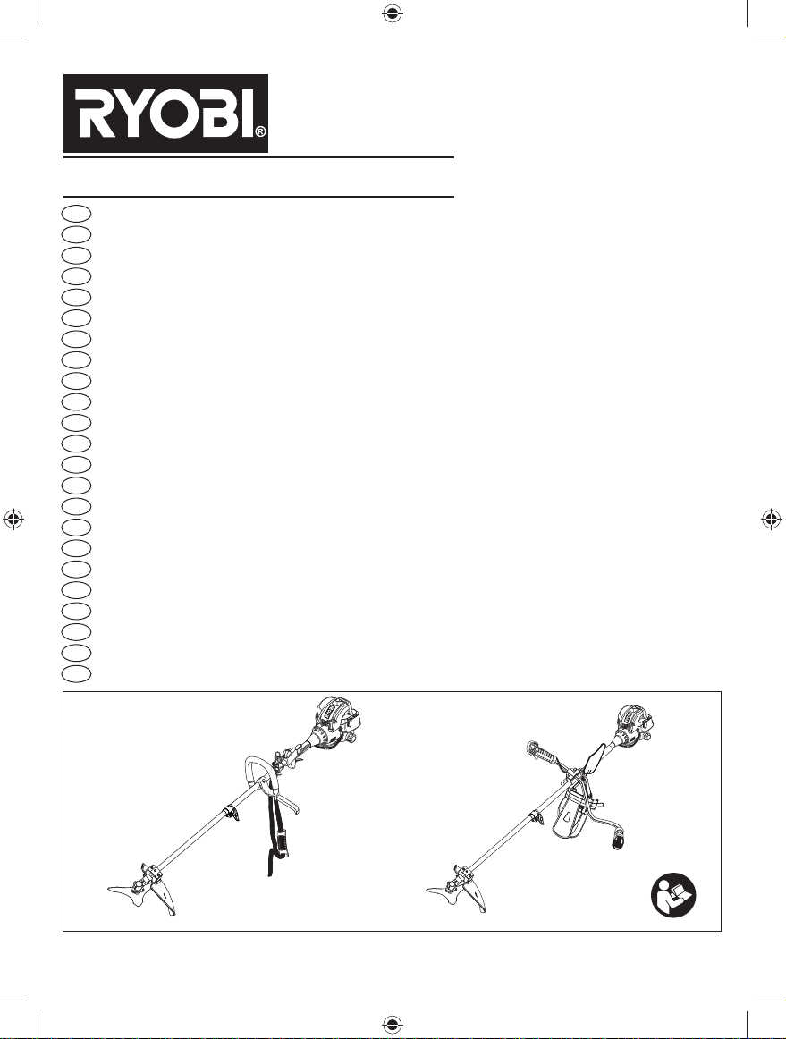
DESCRIPTION
1. Primer Bulb
2. Choke lever
3. Fuel Cap
4. Starter Grip
5. Throttle Lock
6. On / Off Switch
7. Throttle Trigger
8. Rear Handle (RBC30SESB)
9. Front Handle (RBC30SESB)
10. Shoulder Strap (RBC30SESB) / Harness
(RBC30SBSB)
11. Shaft
12. Blade Guard
13. Tri-arc Blade
14. Grass Deflector
15. Cutting Line
16. Idle Speed Screw
17. Knob
18. Hanger Cap
19. Trigger Handle (RBC30SBSB only)
20. Left Handle (RBC30SBSB only)
21. Throttle interlock (RBC30SBSB only)
22. ReelEasy
23. Latch
TM
24. Bolt (RBC30SBSB only)
25. Clamp (RBC30SBSB only)
26. Combination wrench (RBC30SBSB only)
27. Bracket (RBC30SBSB only)
28. Bike handle (RBC30SBSB only)
29. Wrench
30. Clamp
31. Screw
32. Bracket (RBC30SESB only)
33. Securing bolt (RBC30SESB only)
34. Pin (RBC30SESB only)
ASSEMBLY
Please refer to Fig. 2a - 2d.
Unpacking
This product requires assembly.
■ Carefully remove the tool and any accessories from
the box. Make sure that all items listed in the packing
list are included.
■ Inspect the tool carefully to make sure no breakage or
damage occurred during shipping.
■ Do not discard the packing material until you have
carefully inspected and satisfactorily operated the tool.
WARNING
If any parts are damaged or missing, do not
operate this tool until the parts are replaced.
Failure to heed this warning could result in
serious personal injury.
WARNING
Do not attempt to modify this product or create
accessories not recommended for use with this
product. Any such alteration or modification is
misuse and could result in a hazardous condition
leading to possible serious personal injury.
WARNING
To prevent accidental starting that could cause
serious personal injury, always disconnect the
engine spark plug wire from the spark plug when
assembling parts.
WARNING
Never attach or adjust any attachment while
power head is running. Failure to stop the engine
may cause serious personal injury.
WARNING
Be certain the knob is fully tightened before
operating equipment; check it periodically for
tightness during use to avoid serious injury.
OPERATION
FUEL AND REFUELING
HANDLING THE FUEL SAFELY
WARNING
Check for fuel leaks. If any are found, correct
them before using the product to prevent fire or
burn injury.
■ Always handle fuel with care, it is highly flammable.
■ Always refuel outdoors where there are no sparks
and flames. Do not inhale fuel vapors.
■ Do not let petrol or lubricant come in contact with
your skin.
■ Keep petrol and lubricant away from the eyes. If
petrol or lubricant comes in contact with the eyes,
wash them immediately with clean water. If irritation is
still present, see a doctor immediately.
■ Clean up spilled petrol immediately.
■ Always transport and store fuel in a container
approved for petroleum.
MIXING THE FUEL
■ This product is powered by a 2-stroke engine and
requires pre-mixing petrol and 2-stroke lubricant. Premix unleaded petrol and 2-stroke engine lubricant in a
clean container approved for petrol.
■ This engine is certified to operate on unleaded petrol
intended for automotive use with an octane rating
17
(Fig. 3)
Page 11

English (Original instructions)
of 91 ([R + M] / 2) or higher.
■ Do not use any type of pre-mixed petrol / lubricant
from fuel service stations, this includes the premixed petrol / lubricant intended for use in mopeds,
motorcycles, etc.
■ Use full synthetic 2-stroke lubricant only. Do not use
automotive lubricant or 2-stroke outboard lubricant.
■ Mix 2% full synthetic 2-stroke lubricant into the petrol.
This is a 50:1 ratio.
■ Mix the fuel thoroughly and also each time before
fueling.
■ Mix in small quantities. Do not mix quantities larger
than usable in a 30 day period. Full synthetic 2-stroke
lubricant containing a fuel stabilizer is recommended.
FILLING THE TANK
WARNING
Check for fuel leaks. If any are found, correct
them before using the product to prevent fire or
burn injury.
■ Clean surface around fuel cap to prevent
contamination.
■ Loosen fuel cap slowly to release pressure and to
keep fuel from escaping around the cap.
■ Carefully pour fuel mixture into the tank. Avoid spillage.
■ Prior to replacing the fuel cap, clean and inspect
the gasket.
■ Immediately replace fuel cap and hand tighten.
Wipe upany fuel spillage. Move 9 m away from
refueling site before starting engine.
Note: It is normal for smoke to be emitted from a new
engine during and after first use.
WARNING
Always shut off engine before fueling. Never add
fuel to a machine with a running or hot engine.
Move at least 9 m from refueling site before
starting engine. Do not smoke.
STARTING AND STOPPING (Fig. 4a - 4b)
WARNING
Never start or run the engine inside a closed or
poorly ventilated area; breathing exhaust fumes
can kill.
■ Set the switch (6) to the "I" position before trying to
start unit.
TO START A COLD ENGINE:
1. Lay the trimmer on a flat, bare surface.
2. Press the primer bulb (1) 10 times.
NOTE: After the 7th press, the fuel should be visible
in the primer bulb. If not, continue pressing until the
fuel is visible.
3. Set the choke lever (2) to
4. Hold down the throttle lock (5) and then squeeze the
throttle trigger (7).
NOTE: Lock the throttle in position by depressing the
throttle interlock button (21) for RBC30SBSB.
5. Hold the foam handle tightly with left hand and pull
the starter grip (4) upwards with right hand in a quick,
firm and consistent motion until the engine attempts
to start. Do not pull the starter grip more than 4 times.
6. Set the choke lever to
7. Pull the starter grip until the engine starts. Do not pull
the starter grip more than 6 times.
NOTE: If the engine does not start, repeat the
procedure from step 3.
8. Allow the engine to run for 10 seconds, then set the
choke lever to
position.
TO START A WARM ENGINE:
1. Press the primer bulb 10 times.
2. Set the choke lever to
3. Hold down the throttle lock and then squeeze the
throttle trigger.
NOTE: Lock the throttle in position by depressing the
throttle interlock button for RBC30SBSB.
4. Hold the foam handle tightly with left hand and pull
the starter grip upwards with right hand in a quick,
firm and consistent motion until the engine starts.
choke position.
choke position.
choke position.
1 Litre + 20 ml =
2 Litres + 40 ml =
3 Litres + 60 ml = 50:1 (2%)
4 Litres + 80 ml =
5 Litres + 100 ml =
TO STOP THE ENGINE:
■ Press and hold the switch in the stop “ O ” position until
the engine stops.
OPERATING THE TRIMMER (Fig. 5)
RBC30SESB : Hold the trimmer with the right hand on the
18
Page 12

English (Original instructions)
rear handle and the left hand on the front handle.
RBC30SBSB: Hold the trimmer with the right hand on the
trigger handle and the left hand on the left handle.
Keep a firm grip with both hands while in operation. Trimmer
should be held at a comfortable position with the trigger
handle about hip height.
Always operate trimmer at full throttle. Cut tall grass
from the top down. This will prevent grass from wrapping
around the shaft housing and string head which may
cause damage from overheating. If grass becomes
wrapped around the string head, stop the engine,
disconnect the spark plug wire, and remove the grass.
Prolonged cutting at partial throttle will result in lubricant
dripping from the silencer.
CUTTING TIPS (Fig. 6)
When cutting, make sure the cutter head is at a slight
angle as shown while still approximately parallel to the
ground surface. In tall grass, cut from the top down to
ensure the moving parts do not get tangled with the long
grass / brush.
Move the head in steady strokes from left to right as you
work through the grass / brush.
ADVANCING THE LINE (Fig. 7)
FOR REELEASYTM ONLY
If the line becomes short, tap the head on the ground
as shown to extend more line. Take care not to ‘crash’ it
against a hard surface.
OPERATING THE BRUSHCUTTER (Fig. 5)
RBC30SESB: Hold the brushcutter with the right hand on
the rear handle and the left hand on the front handle.
RBC30SBSB: Hold the brushcutter with the right hand on
the trigger handle and the left hand on the left handle.
Keep a firm grip with both hands while in operation.
Brushcutter should be held at a comfortable position with
the trigger handle about hip height. Maintain your grip and
balance on both feet. Position yourself so that you will
not be drawn off balance by the kick-back reaction of the
cutting blade.
Adjust the shoulder strap to position the brushcutter at
a comfortable operating position and to assure that the
shoulder strap will reduce the risk of operator contact
with the blade.
Exercise extreme caution when using the blade
with this unit. Blade thrust is the reaction which
may occur when the spinning blade contacts
anything it cannot cut. This contact may cause
the blade to stop for an instant, and suddenly
“thrust” the unit away from the object that was hit.
This reaction can be violent enough to cause the
operator to lose control of the unit. Blade thrust may
occur without warning if the blade snags, stalls or binds.
This is more likely to occur in areas where it is difficult to
see the material being cut. For cutting ease and safety,
approach the weeds being cut from the right to the left.
In the event that an unexpected object or woody stock is
encountered, this could minimise the blade thrust reaction.
CUTTING TECHNIQUE - BLADE (Fig. 8)
WARNING
Extreme care must be taken when using blades
to ensure safe operation. Read the safety
information for safe operation using the blade,
refer to “Specific Safety Rules for Brushcutter
and Blade Use” earlier in this manual.
MAINTENANCE
WARNING
Use only original manufacturer's replacement
parts, accessories and attachments. Failure to
do so can cause possible injury, poor performance and may void your warranty.
■ The cutting attachment must not work in idle mode.
If this requirement is not satisfied, the clutch has
to be adjusted or the machine needs an urgent
maintenance by a qualified technician.
■ You may make adjustments and repairs described
here. For other repairs, have the trimmer serviced by
an authorized service agent.
■ Consequences of improper maintenance may
include excess carbon deposits resulting in loss of
performance and discharge of black lubricant residue
dripping from the muffler.
■ Make sure all guards, straps, deflectors and handles
are properly and securely attached to avoid the risk of
personal injury.
STRING REPLACEMENT (Fig. 9)
FOR REELEASYTM ONLY
■ Ensure the unit is in the off position
■ Remove the spark plug lead to prevent accidental
starting.
■ Use a 2.4mm diameter monofilament string.
■ Cut one piece of string approximately 6 m in length.
■ Rotate the knob on the string head until the line on
knob aligns with the arrows on the top of string head.
19
Page 13

English (Original instructions)
■ Insert one end of the string into the eyelet located
on the side of the string head and push until string
comes out through eyelet on the other side. Continue
to push string through the string head until the middle
section of the string is inside the string head and
string outside the string head is evenly divided on
each side.
■ Rotate the knob on the string head clockwise to wind
the string.
■ Wind the string until approximately 20cm remains
protruding from the string head.
BLADE PROTECTOR (Fig. 10)
Always place the blade protector on the blade when the
unit is not in use. The blade protector has clips round the
edges to snap over the blade and keep it in place. Wear
gloves and be cautious when handling the blade.
NOTE: Always remove the blade protector before
using the unit. If not removed, the blade protector could
become a thrown object as the blade begins to turn.
CLEANING THE EXHAUST PORT AND
SILENCER
Depending on the type of fuel used, the type and amount
of lubricant used, and/or your operating conditions, the
exhaust port and silencer may become blocked with
carbon deposits. If you notice a power loss with your
petrol powered tool, a qualified service technician will
need to remove these deposits to restore performance.
SPARK ARRESTOR
It is recommended to clean or replace the spark arrestor
every 25 hours to ensure proper performance of your
product. Spark arrestors may be in different locations
depending on the model purchased. Please contact
your nearest service dealer for the location of the spark
arrestor for your model.
ATTACHING THE HANGER CAP (Fig. 11)
To use the hanger cap, push in the button and place the
hanger cap over the lower end of the attachment. Slightly
rotate the cap from side to side until the button locks into
place.
NOTE: The secondary hole in the attachment shaft can
be used for hanging purposes as well.
CLEANING THE AIR FILTER SCREEN (Fig. 12)
For proper performance and longer life, keep the air filter
screen clean.
■ Remove the air filter cover by pushing down the latch
while gently pulling out the cover.
■ Brush the air filter screen lightly.
■ Replace the air filter cover by inserting the tabs of the
cover into the slots on the air filter base, then push
the cover up until it latches securely in place.
FUEL CAP
WARNING
A leaking fuel cap is a fire hazard and must be
replaced immediately.
SPARK PLUG (Fig. 13)
This engine uses a Champion RCJ-6Y or equivalent
spark plug with 0.63 mm electrode gap. Use an exact
replacement.
STORAGE (1 MONTH OR LONGER)
■ Drain all fuel from tank into a container approved
for fuel. Run engine until it stops.
■ Clean all foreign material from the trimmer. Store it in
a well-ventilated place that is inaccessible to children.
Keep away from corrosive agents such as garden
chemicals and de-icing salts.
■ Abide by all ISO and local regulations for the safe
storage and handling of fuel. Excess fuel should be
used up in other 2-stroke engine powered equipment.
20
Page 14

English (Original instructions)
TROUBLESHOOTING
IF THESE SOLUTIONS DO NOT SOLVE THE PROBLEM, CONTACT YOUR AUTHORISED SERVICE DEALER.
PROBLEM POSSIBLE CAUSE SOLUTION
Engine will not start.
Engine starts but will not
ac cel er ate.
Engine starts but will only run at
high speed at half choke.
Engine does not reach full speed
and emits ex ces sive smoke.
Engine starts, runs, and Idle speed screw on Contact a servicing dealer.
accelerates but will not idle.
Blade continues to rotate Carburetor requires. Contact a servicing dealer.
at idle speed. adjustment.
Line will not advance. 1. Line welded to itself. 1. Lubricate with silicone spray.
2. Not enough line on 2. Install more line. Refer to “Line Replacement”
spool. earlier in this manual.
3. Line worn too short. 3. Pull lines while alternately pressing down on
4. Line tangled on spool. 4. Remove line from spool and rewind. Refer to
“Line Replacement” earlier in this manual.
5. Engine speed too slow. 5. Advance line at full throttle.
No spark.
No fuel.
Engine is flooded.
Starter rope now harder to
pull than when new.
Old fuel.
Engine requires
approximately three minutes
to warm up.
Carburetor requires
adjustment.
Check lubricant fuel mixture.
Air filter is dirty.
Spark arrestor screen is dirty.
carburetor requires adjustment
The spark plug may be damaged, remove it and check
for dirt and cracks. Replace with a new spark plug.
Push primer bulb until bulb is full of fuel. If bulb does
not fill, primary fuel delivery sys tem is blocked. Con tact
a servicing dealer. If prim er bulb fills, engine may be
flooded, proceed to next item.
Remove spark plug, turn unit so spark plug hole is
aimed at the ground. Rotate the choke dial to “
” position and pull starter cord 10 to 15 times. This
will clear excess fuel from en gine.
which splashed on the product. Clean and reinstall
spark plug. Clean up any spilled fuel and move at
least 9m away before restarting. Pull starter three times
with choke dial at “
choke dial to “
pro ce dure. If engine still fails to start, repeat pro ce dure
with a new spark plug.
Contact a servicing dealer.
Only use fresh fuel mixed with recommended oil. Fuel over
30 days old may prevent the unit from starting.
Allow engine to completely warm up. If engine does
not accelerate after three minutes, contact a ser vic ing
dealer.
Contact a ser vic ing dealer.
Use fresh fuel and the correct 2-stroke lubricant mix.
Clean air filter. Refer to Clean ing the Air Filter Screen
earlier in this manual.
Contact a servicing dealer.
and releasing bump head.
”. If en gine does not start, rotate
” position and repeat normal starting
Remove any fuel
21
Page 15

English (Original instructions)
TROUBLESHOOTING
IF THESE SOLUTIONS DO NOT SOLVE THE PROBLEM, CONTACT YOUR AUTHORISED SERVICE DEALER.
PROBLEM POSSIBLE CAUSE SOLUTION
Grass wraps round shaft 1. Cutting tall grass at 1. Cut tall grass from the top down.
housing and string head. ground level.
2. Operating trimmer at 2. Operate trimmer at full throttle.
part throttle.
Bump knob hard to turn. Screws threads dirty or Clean threads and lubricate with grease - if no
damaged. improvement, replace bump knob.
Lubricant drips from muffler. 1. Operating trimmer at 1. Operate trimmer at full throttle.
part throttle.
2. Check lubricant/fuel mixture. 2.
3. Air filter dirty. 3. Clean per instruction in Maintenance Section.
Use fresh fuel and the correct full synthetic 2-stroke lubricant
mix.
22
Page 16

EN Inspection after dropping or other impacts: Thoroughly inspect the product and identify any affections or damage with
it. Any part that is damaged should be properly repaired or replaced by an authorized service centre.
FR Véri¿ cation après une chute ou autres chocs: Véri¿ ez minutieusement l'appareil et repérez tout dommage éventuel.
Toute pièce endommagée doit être correctement remplacée ou réparée par un service après-vente agréé.
DE Inspektion nach einem Fall oder anderen Schlägen: Inspizieren Sie das Produkt gründlich und identi¿ zieren jegliche BeeinÀ ussung
oder Beschädigung. Jedes beschädigte Teil sollte durch den autorisierten Kundendienst ordnungsgemäß repariert oder ausgetauscht
werden.
ES Inspección tras caídas u otros impactos: Inspeccione cuidadosamente el producto para identi ¿ car cualquier problema o
daño. Cualquier pieza dañada debe ser sustituida o reparada adecuadamente por un centro de servicio autorizado.
IT Controllare l'utensile dopo che è caduto o dopo altri tipi di impatti: Ispezionare il prodotto e identi¿ care eventuali difetti
o danni. Riparare eventuali parti danneggiate o farle sostituire da un centro servizi autorizzato.
NL Controleer het apparaat nadat u het hebt laten vallen of bij impact: Controleer het apparaat grondig en ga alle defecten
of schade na. Een beschadigd onderdeel moet door een geautoriseerd onderhoudscentrum goed worden gerepareerd of
vervangen.
PT Inspecção após quedas ou outros impactos: Inspeccione cuidadosamente o produto para identi¿ car qualquer problema
ou dano. Qualquer peça dani¿ cada deve ser substituída ou reparada adequadamente por um centro de serviço autorizado.
DA Inspektion efter tab eller andre slagpåvirkninger: Produktet skal inspiceres grundigt, og evt. påvirkninger eller skader
skal lokaliseres. Enhver del, som bliver beskadiget, skal repareres ordentligt eller udskiftes på et autoriseret servicecenter.
SV Inspektion efter att produkten tappats eller utsatts för stötar: Kontrollera produkten noggrant för att identi¿ era eventuella
skador på den. Skadade delar skall repareras ordentligt eller bytas ut av en auktoriserad service¿ rma.
FI Tarkastaminen pudottamisen ja muiden iskujen jälkeen: Tarkista tuote huolella ja paikanna kaikki vauriot ja viat.
Valtuutetun huoltopisteen on korjattava tai vaihdettava vioittuneet osat asianmukaisesti.
NO Inspeksjon etter fall og andre former for støt: Det sekundære hullet i tilbehørsskaftet kan også brukes til hengeformål.
Enhver del som er skadet må repareres eller skiftes ut ved et autorisert serviceverksted.
RU Ɉɫɦɨɬɪ ɩɨɫɥɟ ɩɚɞɟɧɢɹ ɢɥɢ ɞɪɭɝɢɯ ɭɞɚɪɨɜ: ȼɧɢɦɚɬɟɥɶɧɨ ɨɫɦɨɬɪɢɬɟ ɭɫɬɪɨɣɫɬɜɨ ɧɚ ɨɬɫɭɬɫɬɜɢɟ ɩɨɜɪɟɠɞɟɧɢɣ ɢ
ɩɨɥɨɦɨɤ. ȼ ɫɥɭɱɚɟ ɩɨɜɪɟɠɞɟɧɢɹ ɤɚɤɨɣ-ɥɢɛɨ ɞɟɬɚɥɢ ɧɟɨɛɯɨɞɢɦɨ ɨɛɪɚɬɢɬɶɫɹ ɜ ɚɜ
ɜɵɩɨɥɧɟɧɢɹ ɧɚɞɥɟɠɚɳɟɝɨ ɪɟɦɨɧɬɚ ɢɥɢ ɡɚɦɟɧɵ.
PL Sprawdzenie po upuszczeniu lub innych uderzeniach: NaleĪy dokáadnie sprawdziü produkt w celu stwierdzenia
wszelkich uszkodzeĔ.
CS Prohlídka po pádu þi jiných úderech: Výrobek ĜádnČ prohlédnČte a zjistČte vady þi poškození. Jakýkoliv poškozený díl je
nutné správnČ opravit nebo nechat vymČnit v autorizovaném servisním stĜedisku.
HU Leesés vagy más ütés utáni átvizsgálás: Alaposan vizsgálja át a terméket, és keresse meg az esetleges behatásokat
vagy sérüléseket. A sérült alkatrészeket egy hivatalos szervizközpontban kell megjavíttatni vagy kicseréltetni.
RO InspecĠia după cădere sau alte impacturi: InspectaĠi amănunĠit produsul úi identi¿ caĠi orice defecĠiuni sau pagube ale
acestuia. Orice piesă deteriorată trebuie să ¿ e reparată în mod corespunzător sau înlocuită de un service autorizat.
LV P Ɨrbaude pƝc nosviešanas vai citiem triecieniem: RnjpƯgi pƗrbaudiet produktu un nosakiet jebkƗdas radušƗs vainas vai
bojƗjumus. Jebkura bojƗta detaƺa jƗnodod remontam vai nomaiƼai pilnvarotƗ apkopes centrƗ.
LT Patikrinimas Ƴ
detalĊ leidžiama remontuoti arba keisti tik autorizuotame aptarnavimo centre.
ET Kontrollige pärast mahakukkumist või saadud lööki: Kontrollige saag hoolikalt üle ja tehke kindlaks võimalikud rikked ja
vigastused. Vigastatud osad tuleb lasta pädeval hooldajal parandada või asendada.
HR Provjerite nakon pada ili drugih udara: Temeljito provjerite proizvod i identi¿ cirajte sve utjecaje ili ošteüenja. Svaki
ošteüeni dio trebao bi pravilno popraviti ili zamijeniti ovlašteni servisni centar.
SL Pregled, þe naprava pade ali prejme drug udarec: Temeljito preglejte izdelek in opazujte, ali je morda poškodovan. Vsak
poškodovani del mora ustrezno popraviti ali zamenjati pooblašþeni servisni center.
SK Kontrola po páde þi iných nárazoch: Dôkladne skontrolujte produkt a zistite na Ėom prípadné poruchy, þi poškodenia.
AkýkoĐvek poškodený diel sa musí náležite opraviĢ alebo vymeniĢ v autorizovanom servisnom centre.
BG ɉɪɨɜɟɪɤɚ ɫɥɟɞ ɢɡɩɭɫɤɚɧɟ ɢɥɢ ɞɪɭɝɢ ɭɞɚɪɢ: ȼɧɢɦɚɬɟɥɧɨ ɩɪɨɜɟɪɟɬɟ ɩɪɨɞɭɤɬɚ ɢ ɭɫɬɚɧɨɜɟɬɟ ɞɚɥɢ ɟ ɡɚɫɟɝɧɚ
ɩɨɜɪɟ
rankiui nukritus ar po kitǐ smnjgiǐ: Atidžiai patikrinkite prietaisą, ar jis nepažeistas. Bet kurią apgadintą
ɞɚ ɩɨ ɧɟɝɨ. ȼɫɹɤɚ ɩɨɜɪɟɞɟɧɚ ɱɚɫɬ ɬɪɹɛɜɚ ɞɚ ɛɴɞɟ ɩɨɩɪɚɜɟɧɚ ɢɥɢ ɡɚɦɟɧɟɧɚ ɨɬ ɭɩɴɥɧɨɦɨɳɟɧ ɫɟɪɜɢɡɟɧ ɰɟɧɬɴɪ.
ɬɨɪɢɡɨɜɚɧɧɵɣ ɫɟɪɜɢɫɧɵɣ ɰ
ɟɧɬɪ ɞɥɹ
ɬ, ɢɥɢ ɢɦɚ
Page 17

ClEaN aNd rEplaCE thE foam filtEr (fig. 14)
EN
■ Remove the air box cover from the engine.
■ Remove the air filter.
■ Clean the foam filter. If damaged, replace immediately.
■ Reinstall the foam filter.
■ Reinstall the air filter.
fr
NEttoyEz Et rEmplaCEz lE filtrE EN moussE
(fig. 14)
■ Retirez le couvercle de la boîte à air du moteur.
■ Retirez le filtre à air.
■ Nettoyez en place le filtre en mousse. Si elles sont
endommagées, faites-les remplacer immédiatement.
■ Remettez en place le filtre en mousse.
■ Remettez le filtre à air.
dE
rEiNiguNg dEs luftfiltErsiEBEs (aBB. 14)
■ Entfernen Sie den Deckel des Luftfilterkastens von dem
Motor.
■ Entfernen Sie die den Luftfilter
■ Reinigen sie den Schaumstofffilter. Ersetzen Sie es
unverzüglich, falls es beschädigt sein sollte.
■ installieren Sie den Schaumstofffilter.
■ Den Luftfilter wieder einbauen.
limpiE y sustituya El filtro dE Espuma (fig.14)
Es
■ Retire la tapa de la caja de aire del motor.
■ Retire el filtro de aire
■ Limpie el filtro de espuma. Si están dañadas, substitúyalas
cuanto antes.
■ Vuelva a instalar el filtro de espuma.
■ Vuelva a instalar el filtro de aire.
it
pulirE E sostituirE il filtro pEr la sChiuma
(fig. 14)
■ Rimuovere il coperchio della scatola dell’aria dal motore.
■ Rimuovere il filtro dell’aria
■ Pulire il filtro in poliuretano. Se appaiono danneggiate,
richiederne l’immediata sostituzione.
■ Reinstallare il filtro in poliuretano.
■ Reinstallare il filtro dell’aria.
maak dE sChuimfiltEr sChooN EN vErvaNg
Nl
dEzE (afB. 14)
■ Verwijder het omstelklepdeksel van de motor.
■ Verwijder de luchtfilter.
■ Reinig de schuimfilter. Bij beschadiging, moeten zij
onmiddellijk worden
■ vervangen.
■ Herbevestig de schuimfilter.
■ Plaats het luchtfilter terug.
limpE E suBstitua o filtro dE Espuma (fig. 14)
pt
■ Retire a tampa da caixa de ar do motor.
■ Retire o filtro de ar.
■ Limpe o filtro de espuma. Se estiverem danificadas, mande
substitui-las imediatamente.
■ Volte a instalar o filtro de espuma.
■ Reinstale o filtro de ar.
da
rENs og udskift skumfiltrEt (fig. 14)
■ Fjern luftdækslet fra motoren.
■ Fjern luftfilteret.
■ Rens skumfilteret. Beskadigede skumfilteret skal udskiftes
omgående.
■ Genmonter skumfilteret.
■ Montér luftfilteret igen.
rENgör oCh sätt tillBaka skumfiltrEt (fig.
sv
14)
■ Ta bort luftlådeskyddet från motorn.
■ Ta bort luftfiltret.
■ Rengör skumgummifiltret. Byt omedelbart ut om den är
skadad.
■ Sätt tillbaka skumgummifiltret.
■ Sätt tillbaka filtret.
fi
puhdista ja vaihda vaahtosuodatiN (kuva 14)
■ Poista imukotelon kansi moottorista.
■ Irrota ilmansuodatin
■ Puhdista vaahtomuovisuodatin. Mikäli ne ovat vialliset,
vaihda ne välittömästi.
■ Asenna vaahtomuovisuodatin.
■ Asenna ilmansuodatin uudelleen.
rENgjør og sEtt tilBakE skumfiltErEt (fig.
No
14)
■ Fjern luftboksdekslet fra motoren.
■ Fjern luftfilteret.
■ Rengjør skumfilteret. Hvis skadet må den øyeblikkelig skiftes
ut.
■ Reinstaller skumfilteret.
■ Sett på plass filteret igjen.
Очистите и устанОвите на местО
ru
пенОпластОвый фильтр(рис . 14)
■ Снимите крышку воздушной камеры с двигателя.
■ Снимите воздушный фильтр.
■ Очистите на пенопластовый фильтр. В случае
повреждения сразу же замените его.
■ Yстановите на пенопластовый фильтр.
■ Установите воздушный фильтр.
Page 18

Une projection de la lame
FR
survenir sans prévenir.
Continued movement of saw
EN
blade after cutting through log.
Die Klinge kann ohne
DE
Vorwarnung zurückschlagen.
ES
Puede producirse un
rebote inesperado
La lama potrà rimbalzare
IT
senza avvertenze se scatta
O impulso da lâmina pode
PT
ocorrer sem aviso
Het maaiblad kan plots
NL
terugslaan
Återkast kan uppstå utan
SV
förvarning
Klinge-tilbageslag kan ske
DA
uden varsel
Slike reaksjoner kan oppstå
NO
uten forvarsel
Tällainen takapotku saattaa
FI
tapahtua varoittamatta
A vágókés hirtelen
HU
kilökődését okozhatja
Odmrštění nože může
CS
nastat bez varování
Отскок режущего
RU
лезвия может произойти
неожиданно
Accelerarea lamei poate să
RO
apară fără avertisment
Zjawisko odrzutu może
PL
wystąpić bez ostrzeżenia
SL
Pride lahko do povratnega
udarca rezila
Odbacivanje noža može se
HR
dogoditi bez upozorenja
Tera põrkumine võib
ET
ilmneda ilma hoiatamata
Geležtės sviedimas gali
LT
pasireikšti be įspėjimo
Asmens rāviens var
LV
negaidīti rasties
Ak sa ostrie zachytí,
SK
zapadne alebo zovrie,
môže bez výstrahy dôjsť k
Обратен тласък може да
BG
възникне изненадващо
Gardez vos mains à
l'écart des lames.
Risk of getting cut,
operate carefully.
Halten Sie die Hände
von den Klingen fern!
Mantenga las manos
alejadas de las hojas.
Tenere le mani lontane
dalle lame.
Mantenha as mãos
afastadas das lâminas.
Houd handen weg van
snijbladen.
Håll händerna borta från
bladen.
Hold hænderne på
afstand af knivene.
Hold hendene vekke fra
kniven.
Pidä kädet kaukana
teristä.
Tartsa a kezeit távol a
késektől.
Udržujte ruce mimo
nože.
Не касайтесь режущих
полотен.
Ţineţi mâinile departe
de lame.
Nie zbliżać rąk do
ostrzy.
Roke držite proč od
rezil.
Držite ruke dalje od
oštrica.
Hoidke käed
lõiketeradest eemal.
Rankas laikykite toliau
nuo geležčių.
Neturiet rokas asmeņu
tuvumā.
Ruky nedávajte do
blízkosti ostrí.
Дръжте ръцете си далеч
от остриетата.
Position marche
Run position
Laufstellung
Posición de
funcionamiento
Posizione di corsa
Posição de
funcionamento
Stand draaien
Körläge
Arbejdsstilling
Kjørestilling
Käyntiasento
Be pozíció
Pracovní poloha
Положение вкл
Poziţia mers
W pozycji "działanie"
Položaj teka
Položaj uključeno
Tööasend
Veikimo padėtis
Ieslēgts stāvoklis
Poloha zapnuté
Включено положение
Mettez le levier de starter en
position "FULL".
Set the choke lever to “FULL”
choke position.
Stellen Sie den Chokehebel
auf die "VOLL" Position.
Coloque la palanca del
estrangulador en posición
“FULL”.
Posizionare la leva dell'aria sulla
posizione “FULL” (Pieno).
Defina a alavanca de controlo
para a posição de “FULL”.
Zet de chokehendel in de
chokestand "FULL".
Ställ in chokespaken i
"FULL"-läge.
Indstil chokerhåndetaget i
chokerposition “FULL” (=fuld).
Sett chokespaken til ”FULL”
chokeposisjon.
Aseta rikastinvipu asentoon
"FULL".
Állítsa a fojtókart „FULL”
(TELJES) fojtás állásba.
Nastavte páku sytiče do
polohy „FULL“.
Установите рычажок дросселя
в положение "FULL" (Полные
обороты).
Setaţi maneta şocului la
poziţia „FULL”.
Ustaw dźwignię ssania w
położeniu „FULL”.
Ročico dušilne lopute
premaknite v položaj »FULL«
(polna zadušitev).
Postavite polugu čoka u
položaj čoka “FULL” (PUNO).
Seadke õhuklapi hoob
asendisse "SULETUD".
Nustatykite droselio svirtį į
“Full” droselio padėtį.
Iestatiet droseles sviru
pozīcijā “FULL” (pilna slodze).
Nastavte páčku sýtiča do
polohy „FULL“.
Поставете дроселния лост на
позиция “FULL” (Пълно).
Mettez le levier de starter en
position "HALF".
Set the choke lever to "HALF"
choke position.
Stellen Sie den Chokehebel
auf die "HALB" Position.
Coloque la palanca del
estrangulador en la posición
“HALF”.
Posizionare la leva dell'aria
sulla posizione “CHOKE”.
Defina a alavanca de controlo
para a posição de “HALF”.
Zet de chokehendel in de
chokestand "HALF".
Ställ in chokespaken i
"HALF"-läge.
Indstil chokerhåndetaget i
chokerposition “HALF” (=halv).
Sett chokespaken til ”HALF”
(halv) chokeposisjon.
Aseta rikastinvipu asentoon
"HALF".
Állítsa a fojtókart „HALF”
(FÉL) fojtás állásba.
Nastavte páku sytiče do
polohy „HALF“.
Установите рычажок дросселя
в положение "HALF" (Половина
оборотов).
Setaţi maneta şocului la
poziţia „HALF”.
Ustaw dźwignię ssania w
położeniu „HALF”.
Ročico dušilne lopute
premaknite v položaj »HALF«
(polovična zadušitev).
Postavite polugu čoka u
položaj čoka “HALF” (POLA).
Seadke õhuklapi hoob
asendisse "POOL".
Nustatykite droselio svirtį į
“Half” droselio padėtį.
Iestatiet droseles sviru
pozīcijā "HALF" (pusslodze).
Nastavte páčku sýtiča do
polohy „HALF“.
Поставете дроселния лост на
позиция “HALF” (Наполовина).
Page 19

Mettez le contacteur
FR
d'allumage en position "I"
(MARCHE).
Set the ignition switch to the
EN
"I" (ON) position.
Schalten Sie den Zündungsschalter
DE
auf die "I" (AN) Position.
Ponga el interruptor de
ES
encendido en la posición “I”
(ENCENDIDO).
Posizionare l'interruttore di
IT
accensione su “I” (ON).
Coloque o interruptor de
PT
ignição na posição "I" (ON),
ligado.
Plaats de ontstekingsschakelaar
NL
in de stand "I" (AAN).
Sätt tändningskontakten i
SV
läge "I" (PÅ).
Sæt tændingskontakten i
DA
pos. "I" (=ON).
Sett tenningsbryteren til
NO
"I"-posisjon (ON) .
Aseta käynnistyskytkin
FI
asentoon "I" (Päällä).
A gyújtáskapcsolót állítsa „I”
HU
(BE) állásba.
Nastavte spínač zapalování
CS
do polohy "I" (Zap.).
Установите ключ зажигания
RU
в положение "I" (ВКЛ.).
Setaţi comutatorul de aprindere
RO
în poziţia "I" (PORNIT).
PL
Ustawić przełącznik zapłonu
w położeniu ( I ) (ON).
Stikalo za vžig prestavite v
SL
položaj »I« (VKLOP).
Postavite prekidač paljenja
HR
u položaj "I" (Uključeno).
Seadke süütelüliti asendisse
ET
"I" (SEES).
Uždegimo jungiklį nustatykite į „I“
LT
(įjungta) padėtį.
Aizdedzes slēdzi iestatiet
LV
pozīcijā “I” (Iesl.).
Prepnite spínač zapaľovania
SK
do polohy „I“ (zapnuté).
Поставете стартиращия ключ в
BG
позиция „I“ (включено).
Pressez la poire d'amorçage
à 10 reprises.
Press the primer bulb 10
times.
Drücken Sie die
Einspritzpumpe 10 Mal.
Pulse el cebador 10 veces.
Premere la pompetta 10
volte.
Pressione o cartucho
principal 10 vezes.
Druk 10 keer op de
brandstofbalg.
Tryck på primerknappen 10
gånger.
Pres spædebolden ind 10
gange.
Trykk på primerballongen
10 ganger.
Paina pumppauspalloa 10
kertaa.
Nyomja meg az adagolószivattyú
gombját 10-szer.
Stiskněte 10-krát hlavičku
startéru.
Нажмите 10 раз кнопку
подсоса.
Apăsaţi pompa de amorsare
de 10 ori.
Naciśnij pompkę ręczną
paliwa 10 razy.
10-krat pritisnite črpalni
mehurček.
Pritisnite pumpicu za gorivo
10 puta.
Suruge etteandekuplile 10
korda.
Paspauskite užvedimo
lemputę 10 kartų.
Nospiediet degvielas
pumpīti 10 reizes.
Stlačte primárnu banku
10-krát.
Натиснете помпата за
подкачване на горивото 10 пъти.
Tirez sur la poignée du lanceur
jusqu'à ce que le moteur
démarre.
Pull the starter grip until the
engine starts.
Den Startergriff ziehen bis der
Motor anspringt.
Tire de la palanca de arranque
hasta que el motor arranque.
Tirare la leva di avvio fino a che
non si avvia il motore.
Puxe a pega de arranque até que
o motor arranque.
Trek aan de startkoord tot de
motor start.
Dra i startsnöret tills motorn
startar.
Træk i starthåndtaget, til motoren
starter.
Dra starterhåndtaket inntil
motoren starter.
Nykäise käynnistimen kahvasta
siten, että moottori käynnistyy.
Húzza az indítófogantyút addig,
amíg a motor be nem indul.
Tahejte za rukojeť spouštěče, až
se spustí.
Дергайте за ручку стартера,
пока двигатель не запустится.
Trageţi mânerul starterului până
când motorul porneşte.
Pociągnij za uchwyt rozrusznika
tak, aby uruchomić silnik.
Zagonski ročaj povlecite
tolikokrat, da se motor zažene.
Povucite ručku za pokretanje dok
se motor ne pokrene.
Tõmmake starteri käepidemest
kuni mootor käivitub.
TRAUKITE rankinį starterį tol, kol
variklis užsiveda.
Pavelciet palaišanas rokturi līdz
dzinējs sāk darboties.
Poťahujte rukoväť štartéra, kým
sa motor nespustí.
Издърпайте ръкохватката на стартера,
докато двигателят се стартира.
Squeeze the throttle lock and throttle trigger
to run.
Enfoncez le verrouillage de l'accélérateur ainsi
la gâchette de l'accélérateur pour démarrer.
Auslösersicherung und Gashebel zum Betrieb
drücken.
Deslice el bloqueo del acelerador y el gatillo
del acelerador para arrancar el motor.
Premere il dispositivo di blocco e la valvola a
farfalla si avvierà.
Druk op de snelheidsvergrendeling en de
snelheidsregelaar om te draaien.
Deslize o bloqueio do acelerador e o gatilho
do acelerador para arrancar o motor.
Pres gaslåsen og gasudløseren ind for at
starte.
Tryck in gaslåset och gasreglaget för körning.
Käytä laitetta puristamalla kaasuttimen
lukitusta ja kaasuliipaisinta.
Klem inn avtrekkerlåsen og avtrekkeren for
å kjøre.
Нажмите рычажок блокировки и курковый
выключатель.
Nacisnąć przycisk blokady przepustnicy i przycisk
uruchamiania przepustnicy, aby uruchomić urządzenie.
Stiskněte zámek spouště a spoušť plynu pro
chod.
Húzza meg a gázrögzítőt és a gázkart a
működtetéshez.
Strângeţi opritorul acceleraţiei şi declanşatorul
acceleraţiei pentru a porni.
Nospiediet droseļaizbīdņa fiksatoru un
droseles regulatoru, lai uzsāktu darbību.
Jei norite prietaisą įjungti, nuspauskite
perjungiklio užraktą ir droselinį perjungiklį.
Vajutage töötamiseks seguklapi
lukustusnupule ja gaasipäästikule.
Za pokretanje stišćite bravu sklopke gasa i
sklopku.
Za zagon stisnite zaklep ročice za plin in
ročico za plin.
Zariadenie sa spustí stlačením poistného
tlačidla a regulačného spínača.
Стиснете фискатора и дросела, за да
заработил.
Page 20

FR
Temps d'attente 10 secondes.
EN
Waiting time 10 seconds.
DE
Wartezeit 10 Sekunden.
ES
Tiempo de espera 10 segundos.
IT
Tempo di attesa 10 secondi.
PT
Tempo de espera 10 segundos.
NL
Wachttijd 10 seconden.
SV
Väntetid 10 sekunder.
DA
Ventetid 10 sekunder.
NO
Ventetid 10 sekunder.
FI
Odotusaika 10 sekuntia.
HU
Várakozási idő 10 másodpercig.
CS
Čekací doba 10 sekund.
RU
Необходимо подождать 10 секунд.
RO
Timp de aşteptare 10 secunde.
PL
Czas oczekiwania 10 sekund.
SL
Čas čakanja 10 sekund.
HR
Vrijeme čekanja 10 sekundi.
ET
Ooteaeg 10 sekundi.
LT
Laukimo laikas 10 sekundžių.
LV
Gaidīšanas laiks 10 sekundes.
SK
Doba čakania 10 sekúnd.
BG
Време на изчакване 10 секунди.
Pour arrêter le moteur, placez l'interrupteur sur
“O”, en position ARRÊT .
To stop the engine, move the ignition switch to
the “O” stop position .
ZumAbstellen des Motors den Zündschalter in
die “O” Stoppstellung bringen .
Para parar el motor, desplace el interruptor de
encendido a la posición “O” de parada .
Per arrestare il motore, portare l’interruttore di
accensione in posizione “O” .
Para parar o motor, coloque o interruptor de
ignição na posição “O” de paragem .
Om de motor af te zetten, zet u de
contactschakelaar in de stopstand “O” .
För att stanna motorn, flytta tändningen till läget
"O" stopp .
Motoren standser, når tændingskontakten
sættes på “O” .
For å stoppe motoren, trykker du bryteren til
“O”-stillingen .
Pysäytä moottori siirtämällä virtalukko ”O”pysäytysasentoon .
A motor leállításához helyezze a kapcsolót "O"
állásba, KI pozícióba .
Motor nářadí se vypíná nastavením vypínače
do polohy "O", tj. do polohy "VYPNUTO" .
Чтобы остановить мотор поставьте
выключатель на "О", в положение ВЫКЛ .
Pentru a opri motorul, puneţi întrerupătorul în
poziţia "O", în poziţia OPRIT .
Aby zatrzymać silnik, ustawić wyłącznik na
pozycję "O", w pozycji ZATRZYMANIE .
Da bi zaustavili motor, pomaknite stikalo za
vžig v položaj “O” za zaustavitev .
Da biste zaustavili motor, stavite sklopku u
položaj “O”, na ZAUSTAVLJENO .
Mootori seiskamiseks seadke lüliti asendisse
“O” .
Kad išjungtumėte variklį, perjunkite jungiklį į
“O”, išjungimo padėtį .
Dzinēju aptur, pagriežot slēdzi izslēguma
stāvoklī, kas apzīmēts ar “O” .
Motor vypnete prepnutím spínača zapaľovania
do polohy “O” (vypnuté) .
Двигателят се изключва, като поставите
превключвателя на "O" в положение за СПИРАНЕ .
Le niveau de puissance sonore garanti est
111 d B
.
Guaranteed sound power level is 111 d B.
Der garantierte Schallleistungspegel
beträgt 111 d B.
El nivel de potencia sonoro garantizado es
de 111 d B.
Il livello garantito di potenza sonora è di
111 d B.
O nível de potência sonoro garantido é
de 111 d B.
Het gegarandeerd geluidsniveau bedraagt
111 d B.
Garanterad ljudnivå är 111 d B.
Det garanterede lydeffektniveau er 111 dB.
Garantert lydeffektnivå er 111 dB.
Taattu äänenteho on 111 dB.
Garantált hangteljesítményszint: 111 d B.
Zaručená hladina akustického výkonu je
111 d B.
Гарантируемый уровень звуковой
мощности составляет
Nivelul de putere sonoră garantat este
de 111 d B.
Maksymalny poziom natężenia hałasu
wynosi 111 d B.
Zajamčena raven zvočne moči je 111 d B.
Jamčena razina zvučne snage 111 d B.
Garanteeritud helivõimsuse tase on 111
dB
.
Garantuotas garso galios lygis yra 111 d B.
Garantētais skaņas jaudas līmenis ir
111 d B.
Garantovaná hladina akustického výkonu
je 111 d B.
Гарантираното ниво на шум е 111 d B.
111 d B.
Page 21

Conformité GOST-R
FR
GOST-R Conformity
EN
GOST-R-Konformität
DE
Conformidad con GOST-R
ES
Conformità GOST-R
IT
Conformidade GOST-R
PT
GOST-R-conformiteit
NL
GOST-R-konformitet
SV
GOST-R Overensstemmelse
DA
GOST-R samsvar
NO
GOST-R-vastaavuus
FI
GOST-R megfelelőség
HU
Shoda GOST-R
CS
Соответствие требованиям GOST-R
RU
Conform GOST-R
RO
Zgodność GOST-R
PL
Skladnost GOST-R
SL
HR
Sukladno GOST-R
ET
GOST-R vastavus
GOST-R suderinimas
LT
LV
GOST-R atbilstība
SK
GOST-R konformita
BG
GOST-R Съответствие
Page 22

English Français Deutsch Español Italiano Nederlands Português
Dansk Svenska Suomi Norsk Русский
Model Modell Malli Modell Модель RBC30SESB RBC30SBSB
Vibration (ISO22867): Vibration (ISO22867): Vibration (ISO22867): Vibrasjon (ISO22867): Вибрация (ISO22867):
Forhåndtag Främre handtag Etukädensija Fremre håndtak Передняя ручка
Tomgang Tomgångskörning Tyhjäkäynnillä Tomgang На холостом ходу 3.5/6.6 m/s²
Tophastighed Racing Huipponopeudella Rusing При работе 20.0/20.6 m/s²
Ækvivalent total
vibrationsniveau
Baghåndtag Bakre handtag Takakädensija Bakre håndtak Задняя ручка
Tomgang Tomgångskörning Tyhjäkäynnillä Tomgang На холостом ходу 6.4/7.4 m/s²
Tophastighed Racing Huipponopeudella Rusing При работе 15.0/20.6 m/s²
Ækvivalent total
vibrationsniveau
Usikkerhed Osäkerhet Epätarkkuus Usikkerhet Погрешность 1.5 m/s²
Vibration (ISO22867): Vibration (ISO22867): Vibration (ISO22867): Vibrasjon (ISO22867): Вибрация (ISO22867):
Venstre håndtag Vänster handtag Vasen kahva Venstre håndtak Левой ручки
Tomgang Tomgångskörning Tyhjäkäynnillä Tomgang На холостом ходу 1.5/1.9 m/s²
Tophastighed Racing Huipponopeudella Rusing При работе 10.8/3.6 m/s²
Ækvivalent total
vibrationsniveau
Højre håndtag Höger handtag Oikea kahva Høyre håndtak Правой ручки
Tomgang Tomgångskörning Tyhjäkäynnillä Tomgang На холостом ходу 4.4/6.1 m/s²
Tophastighed Racing Huipponopeudella Rusing При работе 12.4/11.6 m/s²
Ækvivalent total
vibrationsniveau
Usikkerhed Osäkerhet Epätarkkuus Usikkerhet Погрешность 1.5
Støjniveau Ljudnivå Melutaso Støynivå Уровень шума
Lydtryksniveau på
operatørposition
Tomgang Tomgångskörning Tyhjäkäynnillä Tomgang На холостом ходу 84.6/84.5 dB(A) 86.5/86.6 dB(A)
Tophastighed Racing Huipponopeudella Rusing При работе 104.5/103.1 dB(A) 104.8/104.3 dB(A)
Ækvivalent A-vægtet
lydtryksniveau
A-vægtet lydeffektniveau A-vägd ljudeffektsnivå A-painotettu äänenteho A-vektet lydeffektnivå Уровень A-взвешенной
Tomgang Tomgångskörning Tyhjäkäynnillä Tomgang На холостом ходу 93.5 dB(A) 93.6 dB(A)
Tophastighed Racing Huipponopeudella Rusing При работе 109.5 dB(A) 109.5 dB(A)
Ækvivalent A-vægtet
lydeffektniveau
Usikkerhed Osäkerhet Epätarkkuus Usikkerhet Погрешность 2.5 dB(A) 2.5 dB(A)
Model Modèle Model Modelo Modello Model Modelo
Vibration (ISO 22867): Vibrations (ISO22867): Vibrationen (ISO22867): Vibración (ISO22867): Vibrazione (ISO22867): Trillingen (ISO22867): Vibration (ISO22867):
Front handle Poignée avant Vorderer Haltegriff Mango delantero Manico anteriore Voorste handvat Pega frontal
Idling Au ralenti Leerlauf Al ralentí Al minimo Motor in vrijloop Ao ralenti
Racing En fonctionnement Hohe Drehzahl En funcionamiento In funzione Draaiende motor Em funcionamento
Equivalent vibration
total value
Rear handle Poignée arrière Hinterer Haltegriff Mango trasero Manico posteriore Achterste handvat Pega traseira
Idling Au ralenti Leerlauf Al ralentí Al minimo Motor in vrijloop Ao ralenti
Racing En fonctionnement Hohe Drehzahl En funcionamiento In funzione Draaiende motor Em funcionamento
Equivalent vibration
total value
Uncertainty Incertitude Unsicherheit Incertidumbre Incertezza Onzekerheid Incerteza
Vibration (ISO 22867): Vibrations (ISO22867): Vibrationen (ISO22867): Vibración (ISO22867): Vibrazione (ISO22867): Trillingen (ISO22867): Vibration (ISO22867):
Left handle Poignée gauche Linker griff Empuñadura izquierda Impugnatura sinistra Linker handgreep Punho esquerdo
Idling Au ralenti Leerlauf Al ralentí Al minimo Motor in vrijloop Ao ralenti
Racing En fonctionnement Hohe Drehzahl En funcionamiento In funzione Draaiende motor Em funcionamento
Equivalent vibration
total value
Right handle Poignée droite Rechter griff Empuñadura derecha Impugnatura destra Rechter handgreep Punho direito
Idling Au ralenti Leerlauf Al ralentí Al minimo Motor in vrijloop Ao ralenti
Racing En fonctionnement Hohe Drehzahl En funcionamiento In funzione Draaiende motor Em funcionamento
Equivalent vibration
total value
Uncertainty Incertitude Unsicherheit Incertidumbre Incertezza Onzekerheid Incerteza
Noise level (ISO 22868): Niveau sonore Lärmpegel Nivel sonoro Livello sonoro Geluidsniveau Nível sonoro
Emission sound pressure
level at the operator
position
Idling Au ralenti Leerlauf Al ralentí Al minimo Motor in vrijloop Ao ralenti
Racing En fonctionnement Hohe Drehzahl En funcionamiento In funzione Draaiende motor Em funcionamento
Equivalent A-weight
emission sound pressure
level
A-weighted sound
power level
Idling Au ralenti Leerlauf Al ralentí Al minimo Motor in vrijloop Ao ralenti
Racing En fonctionnement Hohe Drehzahl En funcionamiento In funzione Draaiende motor Em funcionamento
Equivalent A-weight
sound power level
Uncertainty Incertitude Unsicherheit Incertidumbre Incertezza Onzekerheid Incerteza
Valeur totale équivalente
des vibrations
Valeur totale équivalente
des vibrations
Valeur totale équivalente
des vibrations
Valeur totale équivalente
des vibrations
Niveau de pression
sonore émis au niveau de
l'utilisateur
Niveau de pression
sonore équivalent
pondéré A
Niveau de puissance
sonore pondéré-A
Niveau de puissance
sonore équivalent
pondéré A
Entspricht Gesamtwert der
Vibration
Entspricht Gesamtwert der
Vibration
Entspricht Gesamtwert der
Vibration
Entspricht Gesamtwert der
Vibration
Schalldruckpegel in der
Position des Benutzers
Entspricht A-Bewertung
Emissionsschalldruckpegel
A-bewerteter
Schallleistungspegel
Entspricht A-Bewertung
Schallleistungspegel
Valor total de vibración
equivalente
Valor total de vibración
equivalente
Valor total de vibración
equivalente
Valor total de vibración
equivalente
Nivel de presión acústica
de emisión en la posición
del operador
Nivel de potencia acústica
de emisión ponderado A
Nivel de potencia acústica
ponderada en A
Nivel de potencia
acústica sonora
ponderado A
Valore totale delle
vibrazioni equivalenti
Valore totale delle
vibrazioni equivalenti
Valore totale delle
vibrazioni equivalenti
Valore totale delle
vibrazioni equivalenti
Livello di emissioni
pressione sonora alla
posizione dell'operatore
Livello di emissioni
di pressione sonora
equivalente ponderato A
Livello di potenza sonora
pesato A
Livello di potenza sonora
equivalente ponderato A
Equivalente totale
trillingswaarde
Equivalente totale
trillingswaarde
Equivalente totale
trillingswaarde
Equivalente totale
trillingswaarde
Emissie geluidsdrukniveau
in de bedienpositie
Equivalent A-gewicht
emissie geluidsdrukniveau
A-gewogen geluidsniveau Nível de potência sonora
Equivalent A-gewicht
geluidsniveau
Valor total da vibração
equivalente
Valor total da vibração
equivalente
Valor total da vibração
equivalente
Valor total da vibração
equivalente
Nível de emissão de
pressão sonora na
posição do operador
Nível de emissão
de pressão sonora
equivalente à
ponderação A
ponderada A
Nível de potência
sonora equivalente à
ponderação A
Page 23

EN
GUARANTEE
In addition to any statutory rights resulting from the purchase, this product is
covered by a guarantee as stated below.
1. The guarantee period is 24 months for consumers and commences on the
date when the product was purchased. This date has to be documented
by an invoice or other proof of purchase. The product is designed and
dedicated to consumer and private use only. So there is no guarantee
provided in case of professional or commercial use.
2. There is, in some cases (i.e. promotion, range of tools), a possibility to extend
the warranty period over the period described above using the registration on
the www.ryobitools.eu website. The eligibility of the tool is clearly displayed
in stores and/or on packaging. The end user needs to register his/her newlyacquired tools online within 8 days the date of purchase. The end user may
register for the extended warranty in his country of residence if listed on the
online registration form where this option is valid. Furthermore, end users
must give their consent to the storage of the data which are required to enter
online and they have to accept the terms and conditions. The registration
conrmation receipt, which is sent out by e-mail, and the original invoice
showing the date of purchase will serve as proof of the extended warranty.
Your statutory rights remain unaffected.
3. The guarantee covers all defects of the product during the warranty period
due to defaults in workmanship or material at the purchase date. The
guarantee is limited to repair and/or replacement and does not include any
other obligations including but not limited to incidental or consequential
damages. The warranty is not valid if the product has been misused, used
contrary to the instruction manual, or being incorrectly connected. This
guarantee does not apply to
– any damage to the product that is the result of improper maintenance
– any product that has been altered or modified
– any product where original identification (trade mark, serial number)
markings have been defaced, altered or removed
– any damage caused by non-observance of the instruction manual
– any non CE product
– any product which has been attempted to be repaired by an non-
qualified professional or without prior authorization by Techtronic
Industries
– any product connected to improper power supply (amps, voltage,
frequency)
– any product used with inappropriate fuel mixture (fuel, oil, percentage
of oil)
– any damage caused by external influences (chemical, physical,
shocks) or foreign substances
– normal wear and tear of spare parts
– inappropriate use, overloading of the tool
– use of non-approved accessories or parts
– carburettor after 6 months, carburettor adjustments after 6 months
– components (parts and accessories) subject to natural wear and tear,
including but not limited to bump knobs, drive belts, clutch, blades
of hedge trimmers or lawn mowers, harness, cable throttle, carbon
brushes, power cord, tines, felt washers, hitch pins, blower fans, blower
and vacuum tubes, vacuum bag and straps, guide bars, saw chains,
hoses, connector fittings, spray nozzles, wheels, spray wands, inner
reels, outer spools, cutting lines, spark plugs, air filters, gas filters,
mulching blades, etc.
4. For servicing, the product must be sent or presented to an RYOBI authorized
service station listed for each country in the following list of service station
addresses. In some countries your local RYOBI dealer undertakes to send
the product to the RYOBI service organisation. When sending a product
to an RYOBI service station, the product should be safely packed without
any dangerous contents such as petrol, marked with sender’s address and
accompanied by a short description of the fault.
5. A repair/replacement under this guarantee is free of charge. It does not
constitute an extension or a new start of the guarantee period. Exchanged
parts or tools become our property. In some countries delivery charges or
postage will have to be paid by the sender.
6. This guarantee is valid in the European Community, Switzerland, Iceland,
Norway, Liechtenstein, Turkey and Russia. Outside these areas, please
contact your authorized RYOBI dealer to determine if another warranty
applies.
AUTHORISED SERVICE CENTRE
To nd an authorised service centre near you, visit uk.ryobitools.eu.
GARANTIE
FR
En plus des droits statutaires liés à l'achat, ce produit est couvert par une
garantie telle que décrite ci-dessous.
1. La durée de la garantie accordée au consommateur est de 24 mois à partir
de la date d'achat. Cette date doit être authentiée par une facture ou
tout autre preuve d'achat. Le produit a été conçu en vue d'une utilisation
strictement privée. Aucune garantie ne s'applique donc en cas d'utilisation
professionnelle ou commerciale.
2. Il existe, dans certains cas (par exemple promotion, gamme d'outils),
une possibilité d'étendre la période de garantie au-delà de la période
précédemment décrite en utilisant le formulaire d'enregistrement présent
sur le site Internet www.ryobitools.eu. L'éligibilité d'un outil est clairement
afchée dans les points de vente et/ou sur l'emballage. L'utilisateur nal doit
enregistrer son/ses outil(s) nouvellement acheté(s) en ligne dans les 8 jours
qui suivent la date d'achat. L'utilisateur a la possibilité de s'enregistrer pour
l'extension de garantie dans son pays de résidence si celui-ci est listé dans
le formulaire d'enregistrement en ligne où cette option est valide. L'utilisateur
nal doit donner son consentement pour l'enregistrement des données
requises pour accéder au site et doit accepter les termes et conditions.
La conrmation d'enregistrement, envoyée par courrier électronique, ainsi
que la facture originale mentionnant la date d'achat serviront de preuve de
l'extension de garantie. Vos droits statutaires restent inchangés.
3. La garantie couvre les défauts des pièces et de main d'oeuvre du produit
pendant la période de garantie à partir de la date d'achat. La garantie
n’inclut aucune autre obligation, tel que, mais sans s'y limiter, les dommages
accessoires ou indirects. La garantie est non valable en cas de mauvaise
utilisation du produit, d'utilisation contraire aux instructions du mode
d'emploi, ou en cas de branchement incorrect. Cette garantie ne s'applique
pas pour :
– tout dommage au produit résultant d'un mauvais entretien
– tout produit ayant été altéré ou modifié
– tout produit dont les marquages originaux d'identification (marque,
numéro de série) ont été dégradés, altérés ou retirés
– tout dommage causé par le non-respect des instructions du mode
d'emploi
– tout produit non CE
– tout produit ayant subi une tentative de réparation par du personnel
non qualifié ou sans autorisation préalable de Techtronic Industries
– tout produit raccordé à une alimentation secteur non conforme
(ampérage, voltage, fréquence)
– tout produit utilisé avec un mélange inapproprié (essence, huile,
pourcentage d'huile)
– tout dommage causé par des influences extérieures (chimiques,
physiques, chocs) ou par des substances étrangères
– l'usure normale des pièces consommables
– une utilisation inappropriée, une surcharge de l'outil
– l'utilisation de pièces ou accessoires non agréés
– les carburateurs après plus de 6 mois à compter de la date d’achat,
également les réglages du carburateur après plus de 6 mois à compter
de la date d’achat
– les composants (pièces et accessoires) sujets à une usure naturelle,
incluant de façon non exhaustive les têtes de fil à frapper, les courroies
de transmission, les embrayages, les lames des taille-haies ou
des tondeuses à gazon, les harnais, les câbles d'accélérateur, les
charbons, les cordons d’alimentation, les fraises de cultivateurs, les
rondelles feutre, les goupilles de fraise, les turbines et lame de broyage
des souffleurs, les tubes de soufflage et d'aspiration des souffleurs,
les sacs de souffleurs et leurs lanières, les guides-chaîne, les chaînes
de tronçonneuses, les tuyaux et raccords, les buses et lances de
nettoyeurs haute pression, les roues, les recharges de fil des têtes de
coupe, les têtes de coupe, le fil de coupe, les bougies d'allumage, les
filtres à air, les filtres à essence, etc.
4. Si le produit doit être réparé, envoyez-le à un service après-vente agréé
RYOBI dont vous trouverez ci-dessous la liste pour chaque pays. Dans
certains pays, votre revendeur RYOBI se chargera d'envoyer le produit à un
centre de réparation RYOBI. Lorsque vous envoyez un produit à un service
après-vente RYOBI, celui-ci doit être correctement emballé, sans contenir
aucun produit dangereux tel que de l'essence, et vous devez indiquer votre
adresse ainsi qu'une courte description du problème.
5. Une réparation / un remplacement sous garantie est gratuit(e). Ceci ne
constituera pas une extension de garantie ni un nouveau départ de la
période de garantie. Les pièces ou les outils remplacés deviennent notre
propriété. Dans certains pays, les frais de port devront être assumés par
l'expéditeur.
6. Cette garantie est valable au sein de l'Europe, de la Suisse, de l'Islande, de
la Norvège, du Liechtenstein, de la Turquie, de la Russie. En dehors de ces
zones, veuillez contacter votre distributeur agréé RYOBI pour déterminer si
une autre garantie s'applique.
SERVICE APRÈS-VENTE AGRÉÉ
Pour trouver le service après-vente agréé le plus proche, rendez-vous sur
fr.ryobitools.eu.
Page 24

EC DECLARATION OF CONFORMITY
EN
Techtronic Industries GmbH
Max-Eyth-Strasse 10, D-71364 Winnenden, Germany
Herewith we declare that the product
String trimmer / Brushcutter
Model number: RBC30SESB / RBC30SBSB
Serial number range:
RBC30SESB: 22301001000001 - 22301001999999
RBC30SBSB: 22301101000001 - 22301101999999
is in conformity with the following European Directives and harmonised
standards
2006/42/EC, 2004/108/EC, 2000/14/EC, 2005/88/EC, 97/68/EC,
2002/88/EC, 2004/26/EC, 2010/26/EU, EN ISO 11806-1:2011, EN ISO
14982:2009, EN ISO 3744:2010
Measured sound power level: 109.5 dB (A), K = 1.5 dB(A)
Guaranteed sound power level: 111 dB (A)
Conformity assessment method to Annex V Directive 2000/14/EC amended
by 2005/88/EC.
Floyd Jeffrey Nesom (BSME)
Senior Director of Engineering
Winnenden, Sep. 30, 2012
Authorised to compile the technical file:
Rainer Kumpf
Techtronic Industries GmbH
Max-Eyth-Strasse 10, D-71364 Winnenden, Germany
EC KONFORMITÄTSERKLÄRUNG
DE
Techtronic Industries GmbH
Max-Eyth-Strasse 10, D-71364 Winnenden, Germany
Hiermit erklären wir, dass die Produkte
Kantenschneider / Freischneidegerät
Modellnummer: RBC30SESB / RBC30SBSB
Seriennummernbereich:
RBC30SESB: 22301001000001 - 22301001999999
RBC30SBSB: 22301101000001 - 22301101999999
mit den folgenden europäischen Richtlinien und harmonisierten Normen
entspricht
2006/42/EC, 2004/108/EC, 2000/14/EC, 2005/88/EC, 97/68/EC,
2002/88/EC, 2004/26/EC, 2010/26/EU, EN ISO 11806-1:2011, EN ISO
14982:2009, EN ISO 3744:2010
Gemessener Schallleistungspegel: 109.5 dB (A), K = 1.5 dB(A)
Garantierter Schallenergiepegel: 111 dB (A)
Konformitätsbeurteilungsmethode zu Anhang V Richtlinie 2000/14/EC,
2005/88/EC geändert. C.
Floyd Jeffrey Nesom (BSME)
Generaldirektor Technik
Winnenden, Sep. 30, 2012
Autorisiert die technische Datei zu erstellen:
Rainer Kumpf
Techtronic Industries GmbH
Max-Eyth-Strasse 10, D-71364 Winnenden, Germany
DÉCLARATION DE CONFORMITÉ EC
FR
Techtronic Industries GmbH
Max-Eyth-Strasse 10, D-71364 Winnenden, Germany
Déclarons par la présente que le produit
Coupe-bordures / Débroussailleuse
Numéro de modèle: RBC30SESB / RBC30SBSB
Étendue des numéros de série:
RBC30SESB: 22301001000001 - 22301001999999
RBC30SBSB: 22301101000001 - 22301101999999
est conforme aux Directives Européennes et Normes Harmonisées suivantes
2006/42/EC, 2004/108/EC, 2000/14/EC, 2005/88/EC, 97/68/EC,
2002/88/EC, 2004/26/EC, 2010/26/EU, EN ISO 11806-1:2011, EN ISO
14982:2009, EN ISO 3744:2010
Niveau de puissance sonore mesuré: 109.5 dB (A), K = 1.5 dB(A)
Niveau de puissance sonore garanti: 111 dB (A)
Méthode d’évaluation de conformité de l’annexe V Directive 2000/14/EC
modiée 2005/88/EC.
Floyd Jeffrey Nesom (BSME)
Directeur Principal de l'ingénierie
Winnenden, Sep. 30, 2012
Autorisé à rédiger le dossier technique:
Rainer Kumpf
Techtronic Industries GmbH
Max-Eyth-Strasse 10, D-71364 Winnenden, Germany
DECLARACIÓN EC DE CONFORMIDAD
ES
Techtronic Industries GmbH
Max-Eyth-Strasse 10, D-71364 Winnenden, Germany
Por la presente declaramos que los productos
Recortadora de hilo / Cortadora de maleza
Número de modelo: RBC30SESB / RBC30SBSB
Intervalo del número de serie:
RBC30SESB: 22301001000001 - 22301001999999
RBC30SBSB: 22301101000001 - 22301101999999
se encuentra en conformidad con las siguientes Directivas Europeas y normas
armonizadas
2006/42/EC, 2004/108/EC, 2000/14/EC, 2005/88/EC, 97/68/EC,
2002/88/EC, 2004/26/EC, 2010/26/EU, EN ISO 11806-1:2011, EN ISO
14982:2009, EN ISO 3744:2010
Nivel de potencia acústica medido: 109.5 dB (A), K = 1.5 dB(A)
Nivel de potencia acústica garantizado: 111 dB (A)
Método de evaluación de conformidad con el anexo V Directiva 2000/14/EC
modicada por la 2005/88/EC.
Floyd Jeffrey Nesom (BSME)
Director sénior de Ingeniería
Winnenden, Sep. 30, 2012
Autorizado para elaborar la ficha técnica:
Rainer Kumpf
Techtronic Industries GmbH
Max-Eyth-Strasse 10, D-71364 Winnenden, Germany
Page 25

960606010-01
 Loading...