

Page 1
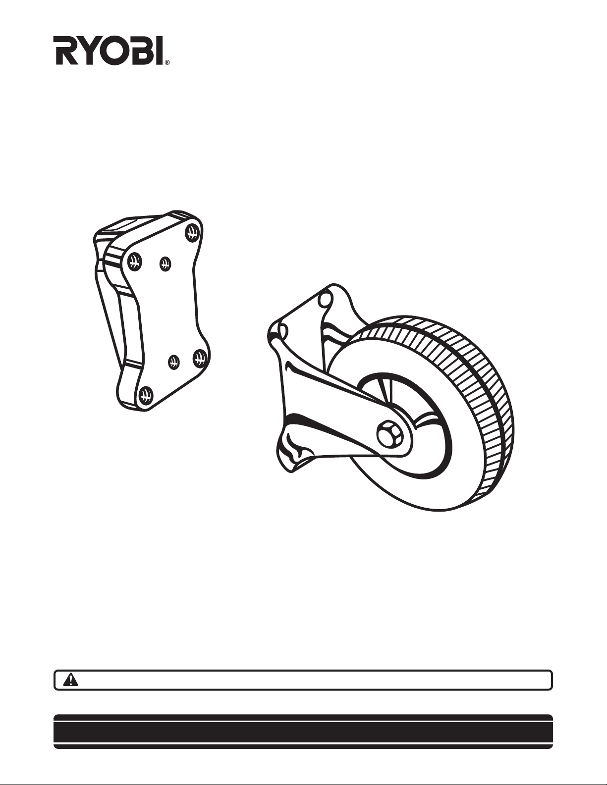
OPERATOR'S MANUAL
Casters
4010331
(For use with BT3000 & BT3100 Table Saws)
Your new casters have been engineered and manufactured to Ryobi's high standard for dependability, ease of
operation, and operator safety. Properly cared for, they will give you years of rugged, trouble-free performance.
WARNING: To reduce the risk of injury, the user must read and understand the operator’s manual.
Thank you for buying a Ryobi accessory kit.
SAVE THIS MANUAL FOR FUTURE REFERENCE
Page 2
RULES FOR SAFE OPERATION
Safe operation of this accessory requires that you read
and understand this operator's manual, the operator’s
manual for the table saw and all labels affixed to the tool.
READ ALL INSTRUCTIONS
■ KNOW YOUR ACCESSORY. Read the operator's
manual carefully. Learn the product's applications
and limitations as well as the specific potential hazards related to this product.
■ KEEP THE WORK AREA CLEAN. Cluttered work
areas and work benches invite accidents. DO NOT
leave tools or pieces of wood on the saw while
operating.
The purpose of safety symbols is to attract your attention to possible dangers. The safety symbols, and the
explanations with them, deserve your careful attention and understanding. The safety warnings do not by
themselves eliminate any danger. The instructions or warnings they give are not substitutes for proper accident
prevention measures.
SYMBOL MEANING
■ ALWAYS WEAR SAFETY GLASSES WITH SIDE
SHIELDS. Everyday eyeglasses have only impact-
resistant lenses; they are NOT safety glasses.
■ DO NOT USE THIS PRODUCT WITH OTHER
EQUIPMENT or for other purposes.
■ ALWAYS DISCONNECT THE SAW FROM THE
POWER SUPPLY BEFORE ASSEMBLING THIS
KIT. Make sure the switch is off when reconnecting
the saw to a power supply.
■ SAVE THESE INSTRUCTIONS. Refer to them frequently and use them to instruct other users. If you
loan someone this product, also loan these instructions.
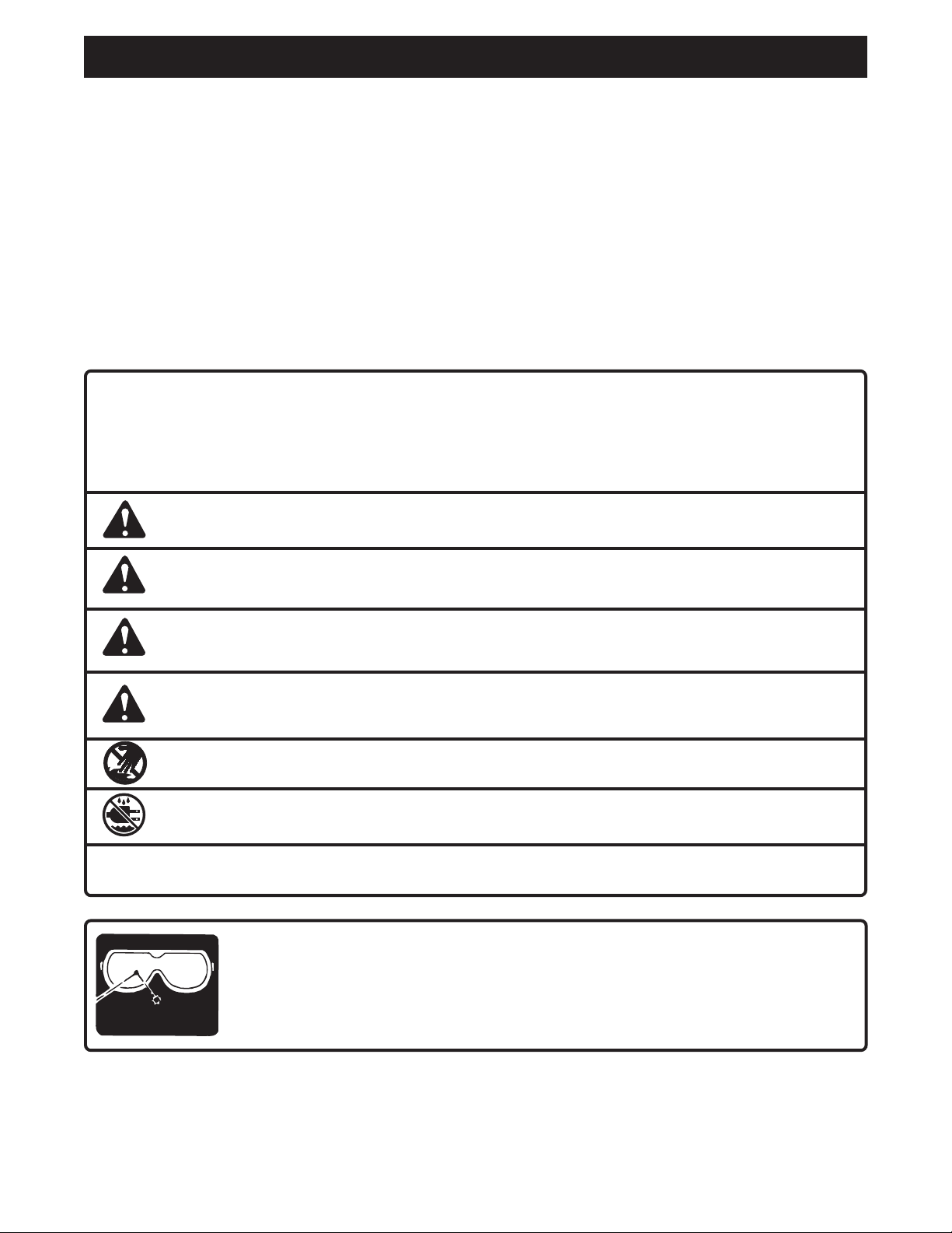
SAFETY ALERT SYMBOL: Indicates danger, warning or caution. May be used in conjunction
with other symbols or pictographs.
DANGER: Failure to obey a safety warning will result in serious injury to yourself or to others.
Always follow the safety precautions to reduce the risk of fire, electric shock and personal injury.
WARNING: Failure to obey a safety warning can result in serious injury to yourself or to others.
Always follow the safety precautions to reduce the risk of fire, electric shock and personal injury.
CAUTION: Failure to obey a safety warning may result in property damage or personal injury to
yourself or to others. Always follow the safety precautions to reduce the risk of fire, electric shock
and personal injury.
NO HANDS: Failure to keep your hands away from the blade will result in serious personal injury.
WET CONDITIONS ALERT: Do not expose to rain or use in damp locations.
NOTE: Advises you of information or instructions vital to the operation or maintenance of the equipment.
WEAR
YOUR
SAFETY
FORESIGHT IS BETTER
GLASSES
THAN NO SIGHT
The operation of any power tool can result in foreign objects being thrown into your eyes,
which can result in severe eye damage. Before beginning tool operation, always wear safety
goggles or safety glasses with side shields and a full face shield when needed. We
recommend Wide Vision Safety Mask for use over eyeglasses or standard safety glasses
with side shields. Always wear eye protection which is marked to comply with ANSI Z87.1.
SAVE THESE INSTRUCTIONS
2
Page 3

UNPACKING
INFORMATION
■ Remove the loose parts from the box. Make sure
that all items listed in the loose parts list are included.
■ Inspect all parts carefully to make sure no breakage
or damage occurred during shipping.
■ If any parts are damaged or missing, please call
1-800-525-2579 for assistance.
WARNING:
If any parts are missing, replace the missing parts
before assembling the kit. Failure to do so could
result in serious personal injury.
3
2
5
4
LOOSE PARTS LIST
1. Casters (2)
2. Carriage bolts - 1/4-20 x 3/4 in. (8)
3. Flat washers - 1/4 in. (8)
4. Lock washers - 1/4 in. (8)
5. Hex nuts - 1/4 in. (8)
6. Adaptor (2) (For use with BT3100 stand)
7. Socket head screws - 5/16-18 x 5/8 in. (4)
8. Socket head screws - 5/16-18 x 1/2 in. (8)
9. Flat washers - 5/16 in. (4)
10. Lock washers - 5/16 in. (12)
11. Hex key (1)
6
1
7
9
8
10
11
3
Page 4

ASSEMBLY
WARNING:
The table saw should never be connected to a power
supply when you are assembling or disassembling
parts. Disconnecting the table saw will prevent accidental starting that could cause serious personal
injury.
ATTACHING THE CASTERS (BT3000)
See Figure 1.
Follow these directions to attach the casters to the
BT3000 stand.
■ Align the holes in the caster with the holes in the
BT3000 stand leg.
■ Place the carriage bolts through the caster and holes
in the stand leg.
■ Place the 1/4 in. flat washers onto the carriage
bolts.
■ Place the 1/4 in. lock washers onto the carriage
bolts.
■ Place the hex nuts onto the carriage bolts.
■ Secure tightly with a 1/4 in. wrench.
Fig. 1
ATTACHING THE CASTERS (BT3100)
See Figure 2.
Follow these directions to attach the casters to the
BT3100 stand.
■ Align the holes in the caster with the holes in the
adaptor.
■ Place the 5/16 in. lock washers onto the
5/16-18 x 1/2 socket head screws.
■ Place the 5/16-18 x 1/2 socket head screws through
the caster and into the adaptor.
■ Secure tightly with the hex wrench provided.
■ Place the 5/16 in. flat washers onto the
5/16-18 x 5/8 socket head screws.
■ Place the 5/16 in. lock washers onto the
5/16-18 x 5/8 socket head screws.
■ Align the holes in the adaptor with the holes in the
stand leg.
■ Start with the bottom hole and place the
5/16-18 x 5/8 socket head screws through the holes
in the stand leg and into the adaptor.
■ Secure tightly with the hex key provided.
Fig. 2
MOVING THE TABLE SAW
Follow these directions to move the table saw.
■ Make sure the casters are securely attached to the
stand.
■ Make sure the rip fence, miter fence, and tables are
securely tightened.
■ Remove any loose items from the saw.
■ Clear the floor of all debris.
NOTE: If you need more leverage to lift the saw,
remove the rip fence, miter fence, and tables. Then
slide the extension rails so that the ends (on the
same side as the casters) are flush with the end of
the saw edge.
■ Lift the saw using the extension rails.
■ Move the saw to the desired location.
4
Page 5

NOTES
5
Page 6

OPERATOR'S MANUAL
Casters
4010331
WARRANTY
Ryobi warrants its accessories for a period of 90 days from the date of purchase. Batteries and chargers are
warranted for a period of two years from the date of purchase.
PARTS AND SERVICE
For parts or service, contact your nearest Ryobi authorized service center. Be sure to provide all relevant
information when you call or visit. For the location of the authorized service center nearest you, please call
1-800-525-2579 or visit us online at www.ryobitools.com. When ordering parts, always give the model
number:
MODEL NUMBER
4010331
983000-154
9-02
RYOBI TECHNOLOGIES INC.
1428 Pearman Dairy Road Anderson, SC 29625
Post Office Box 1207 Anderson, SC 29622
1-800-525-2579 www.ryobitools.com
 Loading...