

Page 1
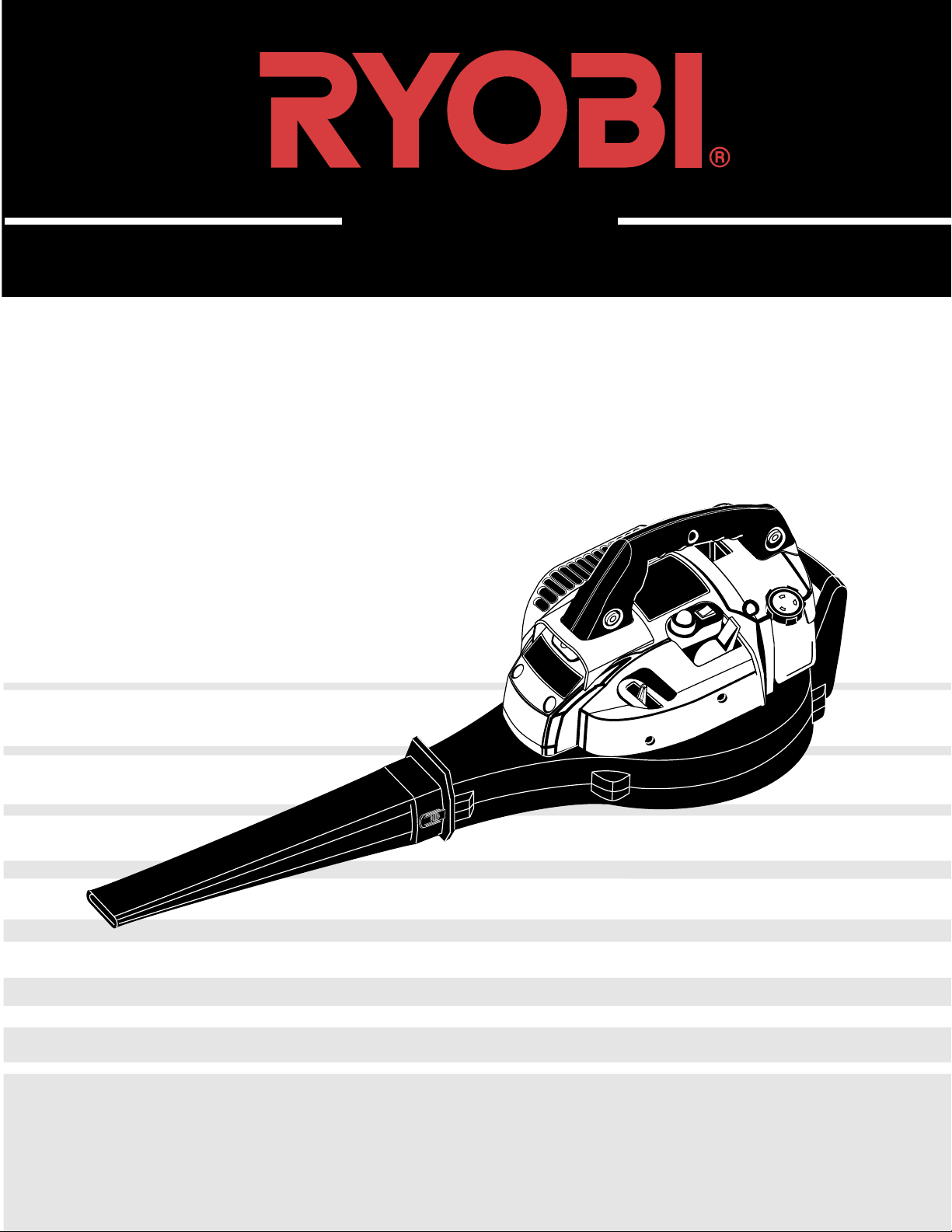
330B – 340BV
2-Cycle Blower – Blower/Vac
OPERATOR’S MANUAL
FOR QUESTIONS, CALL 1-800-345-8746 in U.S. or
1-800-265-6778 in CANADA
www.ryobi.com
IMPORTANT MANUAL DO NOT THROW AWAY
Page 2

INTRODUCTION TABLE OF CONTENTS
2
THANK YOU
Thank you for buying this quality product. This modern
outdoor power tool will provide many hours of useful
service. You will find it to be a great labor-saving device.
This operator’s manual provides you with easy-to-understand operating instructions. Read the whole manual
and follow all the instructions to keep your new outdoor
power tool in top operating condition. The other manual
that came with your power tool, the parts manual, contains all the information that you need to order parts.
PRODUCT REFERENCES, ILLUSTRATIONS AND
SPECIFICATIONS
All information, illustrations and specifications
in this manual are based on the latest product information available at the time of printing. We reserve the right
to make changes at any time without notice.
Copyright© 1999 Ryobi Outdoor Products, Inc.
All Rights Reserved.
SERVICE INFORMATION
Service on this unit both within and after the warranty
period should be performed only by
an authorized and approved service dealer.
Dial:
1-800-345-8746 in the United States or
1-800-265-6778 in Canada
to obtain the listing of the authorized service dealer
nearest you.
DO NOT RETURN THE UNIT TO THE RETAILER.
NOTE: PROOF OF PURCHASE WILL BE REQUIRED
FOR WARRANTY SERVICE.
Make sure this manual is carefully read and understood
before starting or operating this equipment.
THIS PRODUCT IS COVERED BY ONE OR MORE
US PATENTS, OTHER PATENTS PENDING.
I. California Emission Regulations . . . . . . . . . . . . . . . . . 3
II. Rules for Safe Operation . . . . . . . . . . . . . . . . . . . . . 3-8
A. Important Safety Information . . . . . . . . . . . . . . . 4-5
B. Safety and International Symbols . . . . . . . . . . . .6-7
C. Know Your Unit . . . . . . . . . . . . . . . . . . . . . . . . . . . . 8
III. Assembly Instructions . . . . . . . . . . . . . . . . . . . . . . 9-10
A. Assembling Unit as a Blower . . . . . . . . . . . . . . . . 9
B. Assembling Unit as a Vacuum
(Optional Vacuum Kit) . . . . . . . . . . . . . . . . . . . . . . 9
C. Adjusting the Shoulder Harness (Vacuum Kit) . . 10
IV. Oil and Fuel Information . . . . . . . . . . . . . . . . . . . . . . 11
V. Starting/Stopping Instructions . . . . . . . . . . . . . . . . . 12
VI. Operating Instructions . . . . . . . . . . . . . . . . . . . . . 13-14
A. Holding the Blower . . . . . . . . . . . . . . . . . . . . . . . . 13
B. Operating Tips . . . . . . . . . . . . . . . . . . . . . . . . . . . 13
C. Operating as a Vacuum . . . . . . . . . . . . . . . . . . . . 14
VII. Maintenance and Repair Instructions . . . . . . . . . 15-17
A. Maintenance Schedule . . . . . . . . . . . . . . . . . . . . . 15
B. Air Filter Maintenance . . . . . . . . . . . . . . . . . . . . . . 15
C. Carburetor Adjustment . . . . . . . . . . . . . . . . . . . . . 16
D. Replacing the Spark Plug . . . . . . . . . . . . . . . . . . . 17
E. Accessories and replacement parts . . . . . . . . . . . 17
VIII. Cleaning and Storage . . . . . . . . . . . . . . . . . . . . . . . . 18
A. Cleaning . . . . . . . . . . . . . . . . . . . . . . . . . . . . . . . . 18
B. Cleaning the Vacuum Bag . . . . . . . . . . . . . . . . . . 18
C. Storage . . . . . . . . . . . . . . . . . . . . . . . . . . . . . . . . . 18
D. Long Term Storage . . . . . . . . . . . . . . . . . . . . . . . . 18
E. Transporting . . . . . . . . . . . . . . . . . . . . . . . . . . . . . 18
IX. Troubleshooting Chart . . . . . . . . . . . . . . . . . . . . . . . 19
X. Specifications . . . . . . . . . . . . . . . . . . . . . . . . . . . . . . 20
XI. Warranty . . . . . . . . . . . . . . . . . . . . . . . . . . . . . . . 21-22
CONTENTS OF CARTON
This unit should consist of the following:
• Model 330B Blower or Model 340BV Blower/Vac
• Blower Nozzle
∆ Upper Vacuum Tube
∆ Lower Vacuum Tube
∆ Vacuum Bag
• Bottle of 2-Cycle Oil
• Operator's Manual
• Parts Manual
• Product Registration Card
∆ These items are only with the Model 340BV.
A vacuum accessory kit with these items is
available for the Model 330B.
Page 3
CALIFORNIA EMISSION REGULATIONS
3
SPARK ARRESTOR
WARNING!
RULES FOR SAFE OPERATION
NOTE: For users on U.S. Forest Land and in the states of California, Maine, Oregon and Washington. All U.S. Forest
Land and the states of California (Public Resources Codes 4442 and 4443), Oregon and Washington require, by law that
certain internal combustion engines operated on forest brush and/or grass-covered areas be equipped with a spark
arrestor, maintained in effective working order, or the engine be constructed, equipped and maintained for the prevention
of fire. Check with your state or local authorities for regulations pertaining to these requirements. Failure to follow these
requirements could subject you to liability or a fine. This unit is factory equipped with a spark arrestor.
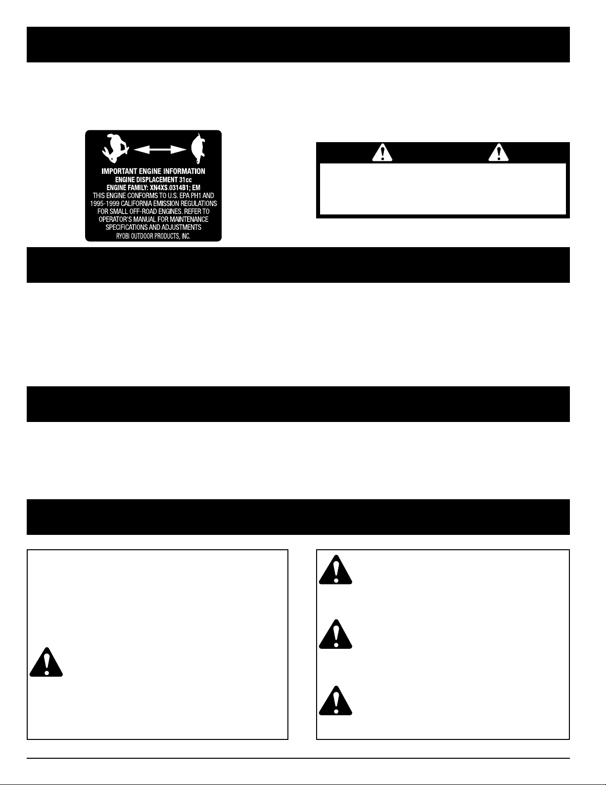
This unit meets the 1999 and later California emissions regulations for small off-road engines. These units are identified by
the label on the engine of your product. A typical identification label is shown.
To ensure that your unit continues to meet these regulations, refer to the following information and instructions in this
operator’s manual.
Read the Operator’s Manual(s) and follow all warnings and safety instructions. Failure to do so can
result in serious injury to the operator and/or bystanders.
WARNING
California Proposition 65 Warning:
THE ENGINE EXHAUST FROM THIS PRODUCT
CONTAINS CHEMICALS KNOWN TO THE STATE
OF CALIFORNIA TO CAUSE CANCER, BIRTH
DEFECTS OR OTHER REPRODUCTIVE HARM.
FOR QUESTIONS, CALL 1-800-345-8746 IN U.S. OR 1-800-265-6778 in CANADA
The purpose of safety symbols is to attract your
attention to possible dangers. The safety symbols,
and their explanations, deserve your careful attention
and understanding. The safety warnings do not by
themselves eliminate any danger. The instructions or
warnings they give are not substitutes for proper
accident prevention measures.
SYMBOL MEANING
SAFETY ALERT SYMBOL: Indicates
danger, warning, or caution. Attention is
required in order to avoid serious personal
injury. May be used in conjunction with
other symbols or pictographs.
NOTE: Advises you of information or instructions vital to
the operation or maintenance of the equipment.
DANGER: Failure to obey a safety warning
will result in serious injury to yourself or to
others. Always follow the safety precautions
to reduce the risk of fire, electric shock, and
personal injury.
WARNING: Failure to obey a safety warning
can result in injury to yourself and others.
Always follow the safety precautions to
reduce the risk of fire, electric shock, and
personal injury.
CAUTION: Failure to obey a safety warning
may result in property damage or personal
injury to yourself or to others. Always follow
the safety precautions to reduce the risk of
fire, electric shock, and personal injury.
Page 4

RULES FOR SAFE OPERATION
4
READ ALL INSTRUCTIONS
BEFORE OPERATING
• Read the instructions carefully. Be familiar with the
controls and proper use of the unit.
• Do not operate this unit when tired, ill, or under the
influence of alcohol, drugs, or medication.
• Children and teens under the age of 15 must not use
the unit, except for teens guided by an adult.
• All guards and safety attachments must be installed
properly before operating the unit.
• Inspect the unit before use. Replace damaged parts.
Check for fuel leaks. Make sure all fasteners are in
place and secure. Replace parts that are cracked,
chipped, or damaged in any way. Do not operate the
unit with loose or damaged parts.
• Carefully inspect the area before starting the unit.
Remove all debris and hard or sharp objects such
as glass, wire, etc.
• Clear the area of children, bystanders, and pets.
At a minimum, keep all children, bystanders and pets
outside a 50 feet (15 m.) radius; there still may be a
risk to bystanders from thrown objects. Bystanders
should be encouraged to wear eye protection. If you
are approached, stop the unit immediately.
SAFETY WARNINGS FOR GAS UNITS
WARNING: Gasoline is highly flammable, and its vapors
can explode if ignited. Take the following precautions:
• Store fuel only in containers specifically designed and
approved for the storage of such materials.
• Avoid creating a source of ignition for spilled fuel. Do
not start the engine until fuel vapors dissipate.
• Always stop the engine and allow it to cool before
filling the fuel tank. Never remove the cap of the fuel
tank, or add fuel, when the engine is hot. Never
operate the unit without the fuel cap securely in place.
Loosen the fuel tank cap slowly to relieve any pressure
in the tank.
• Mix and add fuel in a clean, well-ventilated area
outdoors where there are no sparks or flames. Slowly
remove the fuel cap only after stopping engine. Do not
smoke while fueling or mixing fuel. Wipe up any spilled
fuel from the unit immediately.
• Move the unit at least 30 feet (9.1 m) from the fueling
source and site before starting the engine. Do not
smoke, keep sparks and open flames from the area
while adding fuel or operating the unit.
• IMPORTANT SAFETY INFORMATION •
WHILE OPERATING
• Never start or run the unit inside a closed room or
building. Breathing exhaust fumes can kill. Operate
this unit only in a well ventilated area outdoors.
• To reduce the risk of injury associated with thrown
objects, wear safety glasses or goggles that are
marked as meeting ANSI Z87.1-1989 standards,
• To reduce the risk of hearing loss associated with
sound level(s), always wear ear/hearing protection
when operating this unit.
• Wear heavy, long pants, boots and gloves. Do not
wear, short pants, sandals or go barefoot.
• To avoid static electricity shock, do not wear rubber
gloves or any other insulated gloves while operating
this unit.
• To reduce the risk of injury associated with objects
being drawn into rotating parts, do not wear loose
clothing, jewelry, scarves, and the like. Secure hair
above shoulder level.
• Wear a face or dust mask if the operation is dusty.
Long sleeve shirts are recommended.
• Use the unit only in daylight or good artificial light.
• Keep outside surfaces free from oil and fuel.
• Avoid accidental starting. Be in the starting position
whenever pulling the starter rope. The operator and
unit must be in a stable position while starting. See
Starting/Stopping Instructions.
• Do not set unit on any surface except a clean, hard
area while engine is running. Debris such as gravel,
sand, dust, grass, etc. could be picked up by the air
intake and thrown out by the discharge opening,
damaging unit, property, or causing serious injury to
bystanders or operator.
• Use the right tool. Only use this tool for the purpose
intended.
• Do not force unit. It will do the job better and with less
likelihood of injury at a rate for which it was designed.
• Do not overreach or use from unstable surfaces such
as ladders, trees, steep slopes, rooftops, etc. Always
keep proper footing and balance.
• Always hold the unit with a firm grip when operating.
• Keep hands, face, and feet at a distance from all
moving parts. Do not touch or try to stop the impeller
when it is rotating. Do not operate without guards in
place.
Page 5

RULES FOR SAFE OPERATION
5
• Do not put any object into openings. Do not use with
any opening blocked; keep free of dirt, debris and
anything that may reduce the air flow.
• Do not touch the engine or muffler. These parts get
extremely hot from operation. When turned off they
remain hot for a short time.
• Do not operate the engine faster than the speed
needed to do the job. Do not run the engine at high
speed when not in use.
• Always stop the engine when operation is delayed or
when walking from one location to another.
• Stop the engine for maintenance, repair, to install or
remove the blower tubes or vacuum attachments.
The unit must be stopped and the impeller no longer
turning to avoid contact with the rotating blades.
• Use only genuine Ryobi® replacement parts when
servicing this unit. These parts are available from
your authorized service dealer. Do not use parts,
accessories or attachments not authorized by
Ryobi® for this unit. Doing so could lead to serious
injury to the user, or damage to the unit, and void
your warranty.
• Never use this unit for spreading chemicals,
fertilizers, or other substances which may contain
toxic materials.
• To reduce fire hazard, replace faulty muffler and spark
arrestor, keep the engine and muffler free from grass,
leaves, excessive grease or carbon build up.
WHILE OPERATING UNIT AS A BLOWER
• Never run the unit without the the proper equipment
attached. When using unit as a blower, always install
blower tubes.
• Never point the Blower in the direction of people or
pets, or in the direction of windows. Always direct the
blowing debris away from people, animals, glass, and
solid objects such as trees, automobiles, walls, etc.
WHILE OPERATING UNIT AS A VACUUM
(optional vacuum kit)
• Never run the unit without the the proper equipment
attached. When using unit as a vacuum, always install
vacuum tubes, vacuum bag and make sure the
vacuum bag is completely zipped closed.
• Avoid situations that could catch the vacuum bag
on fire. Do not operate near an open flame. Do not
vacuum warm ash from fireplaces, barbecue pits,
brush piles, etc. Do not vacuum discarded cigars or
cigarettes unless the cinders are completely cool.
• The unit is designed to pickup dry material such as
leaves, grass, small twigs and bits of paper. Do not
attempt to vacuum wet debris and/or standing water
as this may result in damage to the Blower/ Vacuum.
To avoid severe damage to the impeller, do not
vacuum metal, broken glass, etc.
OTHER SAFETY WARNINGS
• Never store the unit, with fuel in the tank, inside a
building where fumes may reach an open flame or
spark.
• Allow the engine to cool before storing or transporting.
Be sure to secure the unit while transporting.
• Store the unit in a dry place, either locked up or up
high to prevent unauthorized use or damage.
Keep out of the reach of children.
• Never douse or squirt the unit with water or any other
liquid. Keep handles dry, clean and free from debris.
Clean after each use, see Cleaning and Storage
instructions.
• Keep these instructions. Refer to them often and use
them to instruct other users. If you loan someone this
unit, also loan them these instructions.
SAVE THESE INSTRUCTIONS
Page 6

SAFETY AND INTERNATIONAL SYMBOLS
This operator's manual describes safety and international symbols and pictographs that may appear on this product.
Read the operator's manual for complete safety, assembly, operating and maintenance and repair information.
SYMBOL MEANING
• SAFETY ALERT SYMBOL
Indicates danger, warning, or caution. May be used in conjunction with other
symbols or pictographs.
• WARNING - READ OPERATOR'S MANUAL
Read the Operator’s Manual(s) and follow all warnings and safety instructions.
Failure to do so can result in serious injury to the operator and/or bystanders.
• FOR SERVICE INFORMATION, CALL:
USA: 1-800-345-8746
CANADA: 1-800-265-6778
• WEAR EYE AND HEARING PROTECTION
WARNING:
Thrown objects and loud noise can cause severe eye injury and hearing loss.
Wear eye protection meeting ANSI Z87.1-1989 standards and ear protection when
operating this unit.
• KEEP BYSTANDERS AWAY
WARNING:
Keep all bystanders, especially children and pets, at least 50 feet (15 m)
from the operating area.
• PRIMER BULB
Push primer bulb, fully and slowly, 5 to 7 times.
• UNLEADED FUEL
Always use clean, fresh unleaded fuel.
• THROWN OBJECTS CAN CAUSE SEVERE INJURY
WARNING:
Keep clear of blower outlet. Never point the blower at yourself or others.
Objects can be thrown from blower. Do not operate unit without proper attachments and
guards in place.
• ON/OFF STOP CONTROL
ON / START / RUN
• ON/OFF STOP CONTROL
OFF OR STOP
RULES FOR SAFE OPERATION
6
Page 7

SYMBOL MEANING
• HOT SURFACE WARNING
Do not touch a hot muffler or cylinder. You may get burned. These parts get extremely
hot from operation. When turned off they remain hot for a short time.
• INDICATES OIL
Refer to operator's manual for the proper type of oil.
• CHOKE CONTROL
A • FULL CHOKE position.
B • PARTIAL CHOKE position.
C • RUN position.
• THROTTLE CONTROL
Indicates “HIGH” or “FASTEST” speed.
• THROTTLE CONTROL
Indicates “IDLE”, “LOW” or “SLOWEST” speed.
• BLOWERS AND BLOWER/VACUUMS – ROTATING IMPELLER BLADES CAN
CAUSE SEVERE INJURY
WARNING:
Stop the engine and allow the impeller to stop before opening the vacuum door,
installing or changing tubes or bag, or before cleaning or performing any maintenance.
RULES FOR SAFE OPERATION
7
Page 8

RULES FOR SAFE OPERATION
8
KNOW YOUR UNIT
Assembled as a Blower
Assembled as a Vacuum
(optional kit for model 330B)
Upper Vac Tube
Lower Vac Tube
Vacuum Inlet Door
Vacuum Inlet Door
Blower Tube
Fuel Cap
Starter Rope Grip
Knob
Vacuum Bag
Shoulder Harness
Vacuum Bag Elbow
Page 9

ASSEMBLY INSTRUCTIONS
9
ASSEMBLING UNIT AS A BLOWER
Blower Tube Assembly
WARNING: To prevent serious personal
injury, stop the engine and allow the impeller
to stop before installing or changing tubes.
WARNING: To prevent serious personal
injury or damage to the unit, the blower tube
must be installed while operating this unit as
a blower.
NOTE: If the unit was assembled as a vacuum unit,
remove all vacuum parts and store away in a
secure place for later use.
Installing
• Install the blower tube over the blower outlet and push
on until both tabs snap into place (Fig. 1).
Removing
• Remove the blower tube by pressing both tabs at the
same time and pulling off the blower (Fig. 1).
ASSEMBLING UNIT AS A VACUUM
(Optional Vacuum Kit)
Vacuum Tube Assembly
WARNING: To prevent serious personal
injury, stop the engine and allow the impeller
to stop before installing or changing tubes.
WARNING: To prevent serious personal
injury or damage to the unit, always install
vacuum tubes, vacuum bag and make sure
the vacuum bag is completely zipped closed
when operating this unit as a vacuum.
NOTE: If the unit was assembled as a blower unit,
remove all blower parts and store away in a
secure place for later use.
Installing
1. Assemble the vacuum tube by installing the lower
tube into the upper tube with the tab on the lower
tube aligning with the notch on the upper tube. Push
the lower tube down and snap into place (Fig. 2)
2. Turn the unit over and open the vacuum door by
pressing the tab button and swinging the door open
(Fig. 3).
Fig. 1
Fig. 2
Fig. 3
Tabs
Tab Button
Notch
Upper Vac Tube
Lower Vac Tube
Tab
Page 10

ADJUSTING THE SHOULDER HARNESS
(Vacuum Kit)
WARNING - Hot Surface:
To prevent
serious personal injury when operating the
unit as a vacuum, hold the unit to the left
side of the body (Fig. 7). The muffler
becomes extremely hot during operation
and can cause burns.
NOTE: Have the vacuum bag harness adjusted prior to
starting the unit.
1. Extend the harness opening fully.
2. Place the harness over your head and onto your right
shoulder. Hold the unit in the operating position to
get a proper adjustment (Fig. 7).
3. Make sure the vacuum bag harness is adjusted to
allow free flow of air into the vacuum bag elbow. If
the bag is kinked, the unit will not perform correctly.
The bottom of the bag should be parallel to the
ground (Fig. 7).
4. Lengthen the harness by pulling down on the strap
and moving the buckle up. Shorten the harness by
pulling the strap back through the buckle while
moving the buckle down (Fig. 8)
ASSEMBLY INSTRUCTIONS
10
Fig. 5
Fig. 6
Fig. 7
Fig. 8
3. Install the upper vacuum tube by hooking under it
the hinge pin of the vacuum door and positioning
the tube to where the knob threads align with the
tapped hole (Figs 4 & 5).
4. Tighten the knob securely. The tube should set even
with the bottom of the unit. Do not over tighten.
5. Install the vacuum bag tube over the blower outlet
and push on until both tabs snap into place (Fig. 6).
Position so the elbow inside the bag slants upwards.
Removing
1. Remove the vacuum bag by pressing both tabs on
the vacuum bag elbow at the same time and pulling
off the blower (Fig. 6).
2. Loosen the knob completely on the vacuum tube,
swing back slightly and unhook from the bottom of
the vacuum door to remove (Figs 4 & 5).
3. Close the vacuum door by pressing down to snap in
place. Ensure the door is secure.
Elbow
Tabs
Page 11

OIL AND FUEL INFORMATION
11
WARNING: Gasoline is extremely
flammable. Ignited Vapors may explode.
Always stop the engine and allow it to cool
before filling the fuel tank. Do not smoke
while filling the tank. Keep sparks and open
flames at a distance from the area.
WARNING: Remove fuel cap slowly to avoid
injury from fuel spray. Never operate the unit
without the fuel cap securely in place.
WARNING: Add fuel in a clean, well
ventilated area outdoors. Wipe up any spilled
fuel immediately. Avoid creating a source of
ignition for spilt fuel. Do not start the engine
until fuel vapors dissipate.
NOTE: Dispose of the old fuel/oil mix in accordance to
Federal, State, and Local regulations.
OIL AND FUEL MIXING INSTRUCTIONS
Old and/or improperly mixed fuel are the main reasons
for the unit not running properly. Be sure to use fresh,
clean unleaded fuel. Follow the instructions carefully for
the proper fuel/oil mixture.
Definition of Blended Fuels
Today's fuels are often a blend of gasoline and oxygenates such as ethanol, methanol or MTBE (ether).
Alcohol-blended fuel absorbs water. As little as 1%
water in the fuel can make fuel and oil separate. It forms
acids when stored. When using alcohol-blended fuel,
use fresh fuel (less than 60 days old).
Using Blended Fuels
If you choose to use a blended fuel, or its use is
unavoidable, follow recommended precautions.
• Always use fresh fuel mix per your operator's manual.
• Use the fuel additive STA-BIL® or an equivalent.
• Always agitate the fuel mix before fueling the unit.
• Drain the tank and run the engine dry before storing
the unit.
Using Fuel Additives
The use of fuel additive, such as STA-BIL® Gas
Stabilizer or an equivalent, will inhibit corrosion and minimize the formation of gum deposits. Using a fuel additive can keep fuel from forming harmful deposits in the
carburetor for up to six (6) months. Add 0.8 oz. (23 ml.)
of fuel additive per gallon of fuel according to the
instructions on the container. NEVER add fuel additives
directly to the unit's fuel tank.
CAUTION: For proper engine operation and
maximum reliability, pay strict attention to the
oil and fuel mixing instructions on the 2-cycle
oil container. Using improperly mixed fuel can
severely damage the engine.
Thoroughly mix the proper ratio of 2-cycle engine oil
with unleaded gasoline in a separate fuel can. Use a 32:1
fuel/oil ratio. Do not mix them directly in the engine fuel
tank. See the table below for specific gas and oil mixing
ratios.
NOTE: One gallon (3.8 liters) of unleaded gasoline mixed
with one 4 oz. (120 ml.) bottle of RYOBI 2 CYCLE
OIL makes a 32:1 fuel/oil ratio.
Page 12

STARTING/STOPPING INSTRUCTIONS
12
Fig. 9
Fig. 10
Fig. 11
STARTING INSTRUCTIONS
WARNING:
Avoid accidental starting. Be in
the starting position whenever pulling the
starter rope. The operator and unit must be
in a stable position while starting.
Also, Do not set unit on any surface except a
clean, hard area while starting. Debris such
as gravel, sand, dust, grass, etc. could be
picked up by the air intake and thrown out
by the discharge opening, damaging unit,
property, or causing serious injury to
bystanders or operator.
WARNING: Operate this unit only
in a well ventilated area outdoors. Carbon
monoxide exhaust fumes can be lethal in a
confined area.
1. Mix gas with oil. Fill fuel tank with fuel/oil mixture.
See Oil and Fuel Mixing Instructions Pg. 11.
NOTE: Have the vacuum bag harness adjusted prior to
starting the unit as a vacuum. See Adjusting the
Shoulder Harness.
NOTE: The On/Off Stop Control is a momentary switch
and is always in the ON position (Fig. 9).
2. Fully press and release primer bulb slowly 5 to 7
times. Fuel should be visible in the bulb (Fig. 9).
If fuel is not visible, press three (3) more times, or
until it is.
3. Place the choke control in the
FULL choke position
( A) (Fig. 9).
4. Place the throttle control in the FAST position ( )
and pull starter rope until engine attempts to start
(1-3 pulls MAXIMUM) (Figs. 10 & 11).
5. Place the choke control in the PARTIAL choke
position ( B) (Fig. 9).
NOTE: The unit will not run in the FULL choke (A)
position.
6. Pull starter rope until engine attempts to run
(1-3 pulls
MAXIMUM) (Fig. 10 & 11).
Page 13

OPERATING INSTRUCTIONS
13
HOLDING THE BLOWER
WARNING: To prevent serious personal
injury to yourself or others, or damage to the
unit, make sure all tubes and guards are in
place before operating your unit.
Check for the following before operating the unit:
• Operator is wearing proper clothing, such as boots,
safety glasses or goggles, ear/hearing protection,
gloves, long pants and long sleeve shirt.
• If the conditions are dusty, a dust mask or face mask
is being worn.
• The unit is in good working condition. The tubes and
guards are in place and secure.
1. Use the unit for cleaning debris away from
driveways, walls and fences (Figs 12 & 13).
2. Use for cleaning around gardens, shrubbery and
trees (Fig. 14)
OPERATING TIPS
• To reduce the risk of hearing loss associated with
sound level(s), the use of hearing protection is
required.
• Operate power equipment only at reasonable hours –
not early in the morning or late at night when people
might be disturbed. Comply with time listed in local
ordinance. Usual recommendations are 9:00 am to
5:00 pm, Monday through Saturday.
• To reduce noise levels, limit the number of pieces of
equipment used at any one time.
• To reduce noise levels, operate power blowers at the
lowest possible speed to do the job.
• Check your equipment before operation, especially
the muffler, air intakes, and air filters.
• Use rakes and brooms to loosen debris before
blowing.
• In dusty conditions, slightly dampen surfaces or use a
mister attachment when water is available.
• Conserve water by using power blowers instead
of hoses for many lawn and garden applications,
including areas such as gutters, screens, patios,
grills, porches, and gardens.
• Watch out for children, pets, open windows, or freshly
washed cars, and blow debris away.
• Use full blower nozzle extension so the air stream can
work close to the ground.
• After using blowers and other equipment, CLEAN UP!
Dispose of debris in trash receptacles.
Page 14

OPERATING INSTRUCTIONS
14
Fig. 15
OPERATING AS A VACUUM
WARNING - Hot Surface:
To prevent
serious personal injury when operating the
unit as a vacuum, hold the unit to the left
side of the body (Fig. 15). The muffler
becomes extremely hot during operation
and can cause burns.
WARNING: To prevent serious personal
injury or damage to the unit, always install
vacuum tubes, vacuum bag and make sure
the vacuum bag is completely zipped closed
when operating this unit as a vacuum.
Check for the following before operating the unit:
• Operator is wearing proper clothing, such as boots,
safety glasses or goggles, ear/hearing protection,
gloves, long pants and long sleeve shirt.
• If the conditions are dusty, a dust mask or face mask
is being worn.
• The unit is in good working condition. The vacuum
tubes and vacuum bag are in place and secure.
• The vacuum bag harness is in place and correctly
adjusted.
1. Use the unit for vacuuming up light debris, leaves,
paper, etc..
Hold the vacuum, tilting the suction tube slightly, and
use a sweeping action to collect light debris (Fig. 15).
The debris will flow into the vacuum bag. Things such as
small leaves and small twigs will be mulched as they
pass through the fan housing, allowing the vacuum bag
to hold more debris.
When the bag is full, suction will noticeably decrease.
Turn off the unit and allow the impeller to stop before
you unzip the bag. Unzip the bag and empty the
contents before continuing. See
Emptying the Vacuum
Bag.
WARNING: To avoid serious personal injury,
never unzip the vacuum bag without first
stopping the unit.
WARNING: As a vacuum, the unit is
designed to pick up dry material such as
leaves, grass, small twigs and bits of paper.
To avoid serious personal injury, do not
attempt to vacuum wet debris and/or
standing water as this may result in damage
to the Blower/ Vacuum. To avoid severe
damage to the impeller, do not vacuum
metal, broken glass, etc.
WARNING: Avoid situations that could
catch the vacuum bag on fire. Do not
operate near an open flame. Do not vacuum
warm ash from fireplaces, barbecue pits,
brush piles, etc. Do not vacuum discarded
cigars or cigarettes unless the cinders are
completely cool.
WARNING: When the upper and lower
vacuum tubes are removed, make sure the
vacuum door is snapped closed before using
the unit, to avoid injury from the impeller.
Emptying the Vacuum Bag
WARNING: To avoid serious personal injury,
turn off the unit and allow the impeller to
stop before opening vacuum door or
installing or removing vacuum bag.
1. Remove the vacuum bag by pressing the tabs on the
elbow tube and pulling it out of the unit, See
Assembling Unit as A Vacuum.
2. Wearing eye protection and a dust mask, unzip the
vacuum bag and empty the contents into a garbage
bag or container.
3. Turn the bag inside out after initial emptying and
vigorously shake out dust and debris.
NOTE: If additional cleaning of the bag is required, see
Cleaning the Vacuum Bag in Maintenance.
4. Zip close and reinstall the vacuum bag.
Page 15

MAINTENANCE AND REPAIR INSTRUCTIONS
15
FREQUENCY MAINTENANCE REQUIRED REFER TO:
Before Starting Engine Fill fuel tank with correct oil and fuel mixture. Page 11
Every 10 Hours Clean and re-oil air filter. Page 15
Every 50 Hours Check spark plug condition and gap. Page 17
NOTE: Some maintenance procedures may require
special tools or skills. If you are unsure about
these procedures take your unit to an authorized
service dealer.
MAINTENANCE SCHEDULE
These required maintenance procedures should be
performed at the frequency stated in the table. They
should also be included as part of any seasonal tune-up.
WARNING: To prevent serious personal
injury, never do maintenance or repairs with
unit running. Always do maintenance and
repairs on a cool unit. Disconnect spark plug
wire to ensure the unit will not start.
Fig. 16
Fig. 19
Fig. 17
Fig. 18
AIR FILTER MAINTENANCE
NOTE: Clean and re-oil the air filter after every 10 hours
of operation. Your unit's air filter is one of the
most important areas to maintain. If it is not
maintained, you will VOID the warranty. Before
cleaning, make sure the unit is turned off.
1. Wipe down the air filter cover and surrounding area.
This will help prevent any debris entering the
carburetor when the cover is removed.
2. Remove the screws on each side of the
carburetor/air filter cover assembly. Remove
the carburetor/air filter cover (Fig. 16).
3. Remove the air filter (Fig. 17).
4. Wash the filter in detergent and water (Fig. 18). Rinse
the filter thoroughly and allow it to dry.
5. Apply enough clean SAE 30 oil to lightly coat the
filter (Fig. 19).
ScrewsAir Filter Cover
Air Filter
Page 16

Fig. 21
MAINTENANCE AND REPAIR INSTRUCTIONS
16
Fig. 20
6. Squeeze the filter to spread the oil (Fig. 20).
7. Reinstall the filter (Fig. 17, Pg 15)
8. Reinstall the carburetor/air filter cover and screws
(Fig. 16, Pg 15). Do not over tighten.
NOTE: Operating the unit without the air filter or
carburetor/air filter cover assembled will
VOID the warranty.
CARBURETOR ADJUSTMENT
The idle speed of the engine is adjustable , the air filter
cover must be removed to do so. Only make adjustments while the unit is assembled as a blower.
NOTE: Careless adjustments can seriously damage
your unit. An authorized service dealer should
make carburetor adjustments.
Check Fuel Mixture
Old and/or improperly mixed fuel is usually the reason
for the unit not running properly. Drain and refill the
tank with fresh, properly mixed fuel prior to making any
adjustments. Refer to Oil and Fuel Information Pg. 11.
Clean Air Filter
The condition of the air filter is important to the operation
of the unit. A dirty air filter will restrict air flow and
change the air/fuel mixture. This is often mistaken for an
out of adjustment carburetor. Check the condition of the
air filter before adjusting the idle speed screw. Refer to
Air Filter Maintenance Pg. 14.
Adjust Idle Speed Screw
WARNING: The unit will be running during
idle speed adjustments. Wear protective
clothing and observe all safety instructions
to prevent serious personal injury.
Also, Do not set unit on any surface except a
clean, hard area during these adjustments.
Debris such as gravel, sand, dust, grass, etc.
could be picked up by the air intake and
thrown out by the discharge opening,
damaging unit, property, or causing serious
injury to bystanders or operator.
If after checking the fuel mixture and cleaning the air
filter the engine still will not idle, adjust the idle speed
screw as follows.
1. Start the engine and let it run with the throttle
control in fast for a minute to warm up. See
Starting/Stopping Instructions, Pg. 12.
2. Shut the unit off and remove the carburetor/air filter
cover. See steps 1 and 2 of Air Filter Maintenance
Pg. 14 .
3. Restart the unit, move the throttle control to the idle
position. If the engine stops, insert a small phillips or
flat blade screwdriver into the idle speed screw
(Fig. 21). Turn the idle speed screw in, clockwise, 1/8
of a turn at a time (as needed) until the engine idles
smoothly.
4. If the engine seems to idle fast, turn the idle speed
screw counterclockwise 1/8 of a turn at a time
(as needed), to reduce idle speed.
5. Before reinstalling the carburetor/air filter cover, turn
the idle speed screw in, clockwise, 1/8 of a turn. This
will compensate for the speed reduction when the
carburetor/air filter cover is back in place.
6. Reinstall the filter (Fig. 17, Pg. 15), carburetor/air
filter cover and screws (Fig. 16, pg. 15).
Checking the fuel mixture, cleaning the air filter, and
adjusting the idle speed screw should solve most engine
problems.
If not and:
• The engine will not idle,
• The engine hesitates or stalls on acceleration,
• There is a loss of engine power,
have the unit checked and adjusted by an authorized
service dealer.
Primer Bulb
Idle Speed
Screw
Choke
Control
Page 17

MAINTENANCE AND REPAIR INSTRUCTIONS
17
REPLACING THE SPARK PLUG
Use a Champion RDJ7Y spark plug (or equivalent).
The correct air gap is 0.020 inch (0.5 mm.). Remove the
plug after every 50 hours of operation and check its
condition.
1. Stop the engine and allow it to cool. Grasp the plug
wire firmly and pull it from the spark plug.
2. Clean around the spark plug. Remove the spark plug
from the cylinder head by turning a 5/8 in. socket
counterclockwise.
3. Replace cracked, fouled or dirty spark plug. Set the
air gap at
0.020 in. (0.5 mm.) using a feeler gauge
(Fig. 22).
CAUTION: Do not sand blast, scrape, or
clean electrodes. Grit in the engine could
damage the cylinder.
4. Install a correctly gapped spark plug in the cylinder
head. Tighten by turning the 5/8 in. socket clockwise
until snug.
If using a torque wrench torque to;
110-120 in.•lb. (12.3-13.5 N•m).
Do not over tighten.
ACCESSORIES/REPLACEMENT PARTS
2-Cycle Oil . . . . . . . . . . . . . . . . . . . . . . . . . . . . . 147543
Spark Plug . . . . . . . . . . . . . . . . . . . . . . . . . . . . . . 610311
Vacuum Tube Assembly . . . . . . . . . . . . . . . . . . . 182480
Vacuum Bag Assembly . . . . . . . . . . . . . . . . . . . . 182476
Vacuum Accessory Kit . . . . . . . . . . . . . . . . . . . . 300031
Blower Tube . . . . . . . . . . . . . . . . . . . . . . . . . . . . 182478
Fuel Cap . . . . . . . . . . . . . . . . . . . . . . . . . . . . . . . 180000
Air Filter . . . . . . . . . . . . . . . . . . . . . . . . . . . . . . . . 182500
0.020 in.
(0.5 mm.)
Fig. 22
CLEARING A BLOCKED IMPELLER
WARNING:
During normal operation, parts
of this unit become hot. Wear protective
clothing and observe all safety instructions
to prevent serious personal injury.
1. Shut off the unit and wait for the engine to come to a
complete stop.
2. Remove the vacuum tubes. See Assembling Unit as
a Vacuum. The vacuum bag can also be removed for
easier handling of the unit.
3. Carefully remove material blocking the impeller.
Inspect the blades to assure no damage has
occurred. Rotate the blades by hand to assure the
blockage is completely cleared.
4. Replace the vacuum bag and vacuum tubes.
5. Restart unit and resume use.
Page 18

CLEANING AND STORAGE
18
LONG TERM STORAGE
If the unit will be stored for an extended time, use the
following storage procedure.
1. Drain all fuel from the fuel tank and drain into a
container with the same 2-cycle fuel mixture. Do not
use fuel that has been stored for more than 60 days.
Dispose of the old fuel/oil mix in accordance to
Federal, State, and Local regulations.
2. Start the engine and allow it to run until it stalls.
This ensures that all fuel has been drained from the
carburetor.
3. Allow the engine to cool. Remove the spark plug
and put 1 oz. (30 ml.) of any high quality motor oil or
2-cycle oil into the cylinder. Pull the starter rope
slowly to distribute the oil. Reinstall the spark plug.
NOTE: Remove the spark plug and drain all of the oil
from the cylinder before attempting to start the
unit after storage.
4. Thoroughly clean the unit and inspect for any loose
or damaged parts. Repair or replace damaged parts
and tighten loose screws, nuts or bolts. The unit is
ready for storage.
TRANSPORTING
• Allow the engine to cool before transporting.
• Secure the unit while transporting.
• Drain fuel from unit.
• Tighten fuel cap before transporting.
CLEANING
WARNING: To avoid serious personal injury,
always turn your unit off and allow it to cool
before you clean or do any maintenance on
it.
• Use a small brush to clean off the outside of the unit
and to keep the air vents free of obstructions.
• Do not use strong detergents or petroleum based
cleaners, such as kerosene. Some household
cleaners contain aromatic oils such as pine and
lemon that can damage the plastic housings or
handles. Wipe off any moisture with a soft cloth.
CLEANING THE VACUUM BAG
1. Empty the bag after each use to avoid deterioration
and obstructing air flow, which will reduce the
performance of the vacuum.
2. Wearing eye protection and a dust mask, clean the
bag as needed. Turn the bag inside out after initial
emptying and vigorously shake out dust and debris.
3. Wash the bag once a year or more often if needed as
follows:
a. Remove the vacuum bag.
b. Turn bag inside out.
c. Hang up.
d. Hose down thoroughly.
e. Hang to dry.
f. Turn bag right side out.
STORAGE
• Never store the unit with fuel in the tank where fumes
may reach an open flame or spark.
• Allow the engine to cool before storing.
• Store the unit locked up to prevent unauthorized use
or damage.
• Store the unit in a dry, well ventilated area.
• Store the unit out of the reach of children.
Page 19

TROUBLESHOOTING
19
CAUSE ACTION
Choke partially on Adjust choke
Dirty air filter Clean or replace the air filter
Too much oil in fuel mixture Drain gas tank / Add fresh fuel mixture
Improper carburetor adjustment Take to an authorized service dealer for
carburetor adjustment
CAUSE ACTION
Old or improperly mixed fuel Drain gas tank / Add fresh fuel mixture
Dirty air filter Clean or replace the air filter
Fouled spark plug Replace or clean the spark plug
Improper carburetor adjustment Take to an authorized service dealer for
carburetor adjustment
Plugged spark arrestor Take to an authorized service dealer for service.
CAUSE ACTION
Empty fuel tank Fill fuel tank with properly mixed fuel
Primer bulb wasn't pressed enough Press primer bulb fully and slowly 5-7 times
Engine flooded Use starting procedure with choke lever in the
RUN position, Pg. 12
Old or improperly mixed fuel Drain gas tank / Add fresh fuel mixture
Fouled spark plug Replace or clean the spark plug
ENGINE WILL NOT START
ENGINE WILL NOT IDLE
ENGINE WILL NOT ACCELERATE
ENGINE LACKS POWER OR STALLS WHEN UNDER LOAD
CAUSE ACTION
Air Filter is Plugged Replace or clean the air filter
Old or improperly mixed fuel Drain gas tank / Add fresh fuel mixture
Improper carburetor adjustment Adjust per instruction Pg. 16
CAUSE ACTION
Old or improperly mixed fuel Drain gas tank / Add fresh fuel mixture
Dirty air filter Clean or replace the air filter
Improper carburetor adjustment Take to an authorized service dealer for
carburetor adjustment
ENGINE SMOKES EXCESSIVELY
Page 20

SPECIFICATIONS
20
Engine Type . . . . . . . . . . . . . . . . . . . . . . . . . . . . . . . . . . . . . . . . . . . . . . . . . . . . . . . . . . . . . . . . . .Air-Cooled, 2-Cycle
Displacement . . . . . . . . . . . . . . . . . . . . . . . . . . . . . . . . . . . . . . . . . . . . . . . . . . . . . . . . . . . . . . . . . . . . . . . . . . . . 28 cc
Operating RPM (Maximum) . . . . . . . . . . . . . . . . . . . . . . . . . . . . . . . . . . . . . . . . . . . . . . . . . . . . . . . 8,000-8,600 rpm
Idle Speed . . . . . . . . . . . . . . . . . . . . . . . . . . . . . . . . . . . . . . . . . . . . . . . . . . . . . . . . . . . . . . . . . . . . . 3,400-4,000 rpm
Blower Output (Maximum) Model 330B . . . . . . . . . . . . . . . . . . . . . . . . . . . . . . . . . . . . . . . . . . . . . . . . .up to 200 MPH
Blower Output (Maximum) Model 340BV . . . . . . . . . . . . . . . . . . . . . . . . . . . . . . . . . . . . . . . . . . . . . . .up to 210 MPH
Vacuum Air Flow (Maximum) Model 340BV . . . . . . . . . . . . . . . . . . . . . . . . . . . . . . . . . . . . . . . . . . . . . .up to 510 CFM
Ignition Type . . . . . . . . . . . . . . . . . . . . . . . . . . . . . . . . . . . . . . . . . . . . . . . . . . . . . . . . . . . . . . . . . . . . . . . . . .Electronic
Ignition Switch . . . . . . . . . . . . . . . . . . . . . . . . . . . . . . . . . . . . . . . . . . . . . . . . . . . . . . . . . . .Momentary Rocker Switch
Spark Plug . . . . . . . . . . . . . . . . . . . . . . . . . . . . . . . . . . . . . . . . . . . . . . . . . . . . . . . . . . . . . . . . . . . . . .Champion DJ7Y
Spark Plug Gap . . . . . . . . . . . . . . . . . . . . . . . . . . . . . . . . . . . . . . . . . . . . . . . . . . . . . . . . . . . . . . . 0.020 in. (0.50 mm)
Lubrication . . . . . . . . . . . . . . . . . . . . . . . . . . . . . . . . . . . . . . . . . . . . . . . . . . . . . . . . . . . . . . . . . . . . . .Fuel/Oil Mixture
Fuel/Oil Ratio . . . . . . . . . . . . . . . . . . . . . . . . . . . . . . . . . . . . . . . . . . . . . . . . . . . . . . . . . . . . . . . . . . . . . . . . . . . . . 32:1
Carburetor . . . . . . . . . . . . . . . . . . . . . . . . . . . . . . . . . . . . . . . . . . . . . . . . . . . . . . . . . . . . . . . .Diaphragm, All-Position
Starter . . . . . . . . . . . . . . . . . . . . . . . . . . . . . . . . . . . . . . . . . . . . . . . . . . . . . . . . . . . . . . . . . . . . . . . . . . . .Auto Rewind
Muffler . . . . . . . . . . . . . . . . . . . . . . . . . . . . . . . . . . . . . . . . . . . . . . . . . . . . . . . . . . . . . . . . . . . . . . . .Baffled with Guard
Throttle . . . . . . . . . . . . . . . . . . . . . . . . . . . . . . . . . . . . . . . . . . . . . . . . . . . . . . . . . . . . . . . . . . . . . . . . . . . . . . . . .Lever
Fuel Tank Capacity . . . . . . . . . . . . . . . . . . . . . . . . . . . . . . . . . . . . . . . . . . . . . . . . . . . . . . . . . . . . . . . . 18 oz. (530 ml)
Weight (Assembled as a Blower) . . . . . . . . . . . . . . . . . . . . . . . . . . . . . . . . . . . . . . . . . . . . . . . . . . . 10.8 Lbs. (4.9 kg)
ENGINE
VACUUM OPTION
Mulching Ration . . . . . . . . . . . . . . . . . . . . . . . . . . . . . . . . . . . . . . . . . . . . . . . . . . . . . . . . . . . . . . . . . . . . . . .Up to 16:1
Vacuum Bag Capacity . . . . . . . . . . . . . . . . . . . . . . . . . . . . . . . . . . . . . . . . . . . . . . . . . . . . . . . . . .2.1 Bushels (40.7 L)
Weight (Assembled as a Vacuum, Vacuum Bag Empty) . . . . . . . . . . . . . . . . . . . . . . . . . . . . . . . . . . 12.5 Lbs. (4.9 kg)
Page 21

21
The California Air Resources Board and Ryobi
Outdoor Products (ROP), are pleased to explain the
emission control system warranty on your 1999 and
later small off-road engine. In California, new small
off-road engines must be designed, built and
equipped to meet the State's stringent anti-smog
standards. ROP must warrant the emission control
system on your small off-road engine for the periods
of time listed below provided there has been no
abuse, neglect or improper maintenance of your small
off-road engine.
Your emission control system may include parts such
as the carburetor or fuel injection system, the ignition
system, and catalytic converter. Also included may be
hoses, belts, connectors and other emission-related
assemblies.
Where a warrantable condition exists, ROP will repair
your small off-road engine at no cost to you including
diagnosis, parts and labor.
The 1999 and later small off-road engines are
warranted for two years. If any emission-related part
on your engine is defective, the part will be repaired
or replaced by ROP.
OWNER'S WARRANTY RESPONSIBILITIES:
• As the small off-road engine owner, you are
responsible for the performance of the required
maintenance listed in your operator's manual. ROP
recommends that you retain all receipts covering
maintenance on your small off-road engine, but
ROP cannot deny warranty solely for the lack of
receipts or for your failure to ensure the
performance of all scheduled maintenance.
• As the small off-road engine owner, you should
however be aware that ROP may deny you warranty
coverage if your small off-road engine or a part has
failed due to abuse, neglect, improper maintenance
or unapproved modifications.
• You are responsible for presenting your small
off-road engine to a Ryobi Authorized Service
Center as soon as a problem exists. The warranty
repairs should be completed in a reasonable
amount of time, not to exceed 30 days.
If you have any questions regarding your warranty
rights and responsibilities, you should call
1-800-345-8746.
MANUFACTURER'S WARRANTY COVERAGE:
• The warranty period begins on the date the engine
or equipment is delivered to the retail purchaser.
• The manufacturer warrants to the initial owner and
each subsequent purchaser, that the engine is free
from defects in material and workmanship which
cause the failure of a warranted part for a period of
two years.
• Repair or replacement of warranted part will be
performed at no charge to the owner at an
Authorized Ryobi Service Center. For the nearest
location, please contact Ryobi at: 1-800-345-8746.
• Any warranted part which is not scheduled for
replacement, as required maintenance which is
scheduled only for regular inspection to the effect of
"Repair or replace as necessary" is warranted for
the warranty period. Any warranted part which is
scheduled for replacement as required maintenance
will be warranted for the period of time up to the
first scheduled replacement point for that part.
• The owner will not be charged for diagnostic labor
which leads to the determination that a warranted
part is defective, if the diagnostic work is performed
at an Authorized Ryobi Service Center.
• The manufacturer is liable for damages to other
engine components caused by the failure of a
warranted part still under warranty.
• Failures caused by abuse, neglect or improper
maintenance are not covered under warranty.
• The use of add-on or modified parts can be
grounds for disallowing a warranty claim. The
manufacturer is not liable to cover failures or
warranted parts caused by the use of add-on or
modified parts.
• In order to file a claim, go to your nearest
Authorized Ryobi Service Center. Warranty services
or repairs will be provided at all Authorized Ryobi
Service Centers.
• Any manufacturer approved replacement part
may be used in the performance of any warranty
maintenance or repair of emission related parts
and will be provided without charge to the owner.
Any replacement part that is equivalent in
performance or durability may be used in
non-warranty maintenance or repair and will
not reduce the warranty obligations of the
manufacturer.
• The following components are included in the
emission related warranty of the engine, air filter,
carburetor, primer, fuel lines, fuel pick up/fuel filter,
ignition module, spark plug and muffler.
CALIFORNIA EMISSION CONTROL WARRANTY STATEMENT
YOUR WARRANTY RIGHTS AND OBLIGATIONS
Page 22

ALL IMPLIED WARRANTIES ARE LIMITED IN
DURATION TO THE TWO (2) YEAR WARRANTY
PERIOD OR NINETY (90) DAYS FOR PRODUCTS
USED FOR ANY COMMERCIAL PURPOSE.
ACCORDINGLY, ANY SUCH IMPLIED WARRANTIES
INCLUDING MERCHANTABILITY, FITNESS FOR A
PARTICULAR PURPOSE, OR OTHERWISE, ARE
DISCLAIMED IN THEIR ENTIRETY AFTER THE
EXPIRATION OF THE APPROPRIATE TWO-YEAR
OR NINETY DAY WARRANTY PERIOD. RYOBI’S
OBLIGATION UNDER THIS WARRANTY, IS STRICTLY
AND EXCLUSIVELY LIMITED TO THE REPAIR OR
REPLACEMENT OF DEFECTIVE PARTS, AND ROP
DOES NOT ASSUME OR AUTHORIZE ANYONE TO
ASSUME FOR THEM ANY OTHER OBLIGATION.
SOME STATES DO NOT ALLOW LIMITATIONS ON
HOW LONG AN IMPLIED WARRANTY LASTS, SO
THE ABOVE LIMITATION MAY NOT APPLY TO YOU.
RYOBI ASSUMES NO RESPONSIBILITY FOR
INCIDENTAL, CONSEQUENTIAL OR OTHER
DAMAGES INCLUDING, BUT NOT LIMITED TO
EXPENSE OF RETURNING THE RYOBI PRODUCT
TO AN AUTHORIZED SERVICE DEALER AND
EXPENSE OF DELIVERING IT BACK TO THE
OWNER, MECHANIC’S TRAVEL TIME, TELEPHONE
OR TELEGRAM CHARGES, RENTAL OF A LIKE
PRODUCT DURING THE TIME WARRANTY SERVICE
IS BEING PERFORMED, TRAVEL, LOSS OR DAMAGE
TO PERSONAL PROPERTY, LOSS OF REVENUE,
LOSS OF USE OF THE PRODUCT, LOSS OF TIME,
OR INCONVENIENCE. SOME STATES DO NOT
ALLOW THE EXCLUSION OR LIMITATION OF
INCIDENTAL OR CONSEQUENTIAL DAMAGES, SO
THE ABOVE LIMITATION OR EXCLUSION MAY NOT
APPLY TO YOU.
This warranty gives you specific legal rights, and you
may also have other rights which vary from state to
state.
This warranty applies to all RYOBI Products
manufactured by RYOBI and sold in the United States
and Canada.
To locate your nearest service dealer dial
1-800-345-8746 in the United States or
1-800-265-6778 in Canada.
RYOBI OUTDOOR PRODUCTS
550 N. 54th Street
Chandler, AZ 85226 U.S.A.
RYOBI CANADA INC.
275 Industrial Rd
Cambridge, Ontario N1R 6K2 CANADA
RYOBI OUTDOOR PRODUCTS warrants each new
RYOBI Product for two (2) years according to the
following terms.
This warranty extends to the original retail purchaser
only and commences on the date of original retail
purchase.
Any part of the RYOBI Product manufactured or
supplied by RYOBI and found in the reasonable
judgement of RYOBI to be defective in material or
workmanship will be repaired or replaced by an
authorized RYOBI service dealer without charge for
parts and labor.
The RYOBI Product including any defective part must
be returned to an authorized service dealer within the
warranty period. The expense of delivering the RYOBI
Product to the dealer for warranty work and the
expense of returning it back to the owner after repair
or replacement will be paid for by the owner. RYOBI’s
responsibility in respect to claims is limited to making
the required repairs or replacements and no claim of
breach of warranty shall be cause for cancellation or
rescission of the contract of sale of any RYOBI
Product. Proof of purchase will be required by the
dealer to substantiate any warranty claim. All warranty
work must be performed by an authorized RYOBI
service dealer.
This warranty is limited to ninety (90) days from the
date of original retail purchase for any RYOBI Product
that is used for rental or commercial purposes, or any
other income-producing purpose.
This warranty does not cover any RYOBI Product that
has been subject to misuse, neglect, negligence, or
accident, or that has been operated in any way
contrary to the operating instructions as specified in
the RYOBI Operator’s Manual. This warranty does not
apply to any damage to the RYOBI Product that is the
result of improper maintenance or to any RYOBI
Product that has been altered or modified so as to
adversely affect the product's operation, performance
or durability or that has been altered or modified so as
to change its intended use. The warranty does not
extend to repairs made necessary by normal wear or
by the use of parts or accessories which are either
incompatible with the RYOBI Product or adversely
affect its operation, performance or durability.
In addition, this warranty does not cover:
A. Tune-ups - Spark Plugs, Carburetor Adjustments,
Filters
RYOBI reserves the right to change or improve the
design of any RYOBI Product without assuming
any obligation to modify any product previously
manufactured.
LIMITED TWO-YEAR WARRANTY
SAVE THESE INSTRUCTIONS FOR FUTURE REFERENCE.
FOR QUESTIONS CALL 1-800-345-8746 IN U.S.
OR 1-800-265-6778 IN CANADA
OPERATOR’S MANUAL PART NO. 182431 REV. B (6922)
PRINTED IN U.S.A. 10/99
 Loading...