

Page 1

325HDA55
Operator
X-series
Please read the operator’s manual carefully and make sure you
′
s manual
325HE3
325HE4
understand the instructions before using the machine.
X-series
X-series
EEEEnnnngggglllliiiisssshh
hh
Page 2

KEY TO SYMBOLS
Symbols
WARNING!
Incorrect or careless use of a hedge trimmer
can turn it into a dangerous tool that can
cause serious or even fatal injury. It is
extremely important that you read and
understand the contents of this operator’s manual.
Always wear:
• Approved hearing protection
• Protective goggles or a visor
This product is in accordance with applicable
EC directives.
Cutting tool. Do not touch the tool without
first switching off the engine.
This machine is not electrically insulated.
If the machine touches or comes close to
high-voltage power lines it could lead to
death or serious bodily injury. Electricity
can jump from one point to another by
arcing. The higher the voltage, the
greater the distance electricity can jump.
Electricity can also travel through
branches and other objects, especially if
they are wet. Always keep a distance of at
least 10 m between the machine and high-voltage power lines
and/or any objects that are touching them. If have to work
within this safe distance you should always contact the
relevant power company to make sure the power is switched
off before you start work.
This machine can be dangerous! The operator of the machine
must ensure, while working, that no persons or animals come
closer than 15 metres.
Other symbols/decals on the machine refer to special
certification requirements for certain markets.
Switch off the engine by moving the stop
switch to the STOP position before carrying
out any checks or maintenance.
Always wear approved protective gloves.
Regular cleaning is required.
Visual check.
Protective goggles or a visor must be worn.
Arrows which show limits for handle
positioning.
Always wear approved protective gloves.
Wear sturdy, non-slip boots.
Noise emission to the environment according
to the European Community’s Directive. The
machine’s emission is specified in chapter
Technical data and on label.
English
2 –
Page 3

CONTENTS
Contents Note the following before starting:
KEY TO SYMBOLS
Symbols ....................................................................... 2
CONTENTS
Contents ...................................................................... 3
Note the following before starting: ................................ 3
SAFETY INSTRUCTIONS
Personal protective equipment ..................................... 4
Machine
Checking, maintaining and servicing the machine
safety equipment .......................................................... 6
General safety precautions .......................................... 8
Safety instructions when using the hedge trimmer ...... 9
WHAT IS WHAT?
What is what? .............................................................. 11
ASSEMBLY
Fitting the hand guard and loop handle ....................... 12
Fitting the handle ......................................................... 12
Fitting the cutting head ................................................ 12
Adjusting the harness .................................................. 12
Fitting the impact guard ............................................... 12
FUEL HANDLING
Fuel .............................................................................. 13
Fuelling ........................................................................ 13
STARTING AND STOPPING
Check before starting ................................................... 14
Starting and stopping ................................................... 14
MAINTENANCE
Carburettor ................................................................... 16
Muffler .......................................................................... 17
Cooling system ............................................................ 18
Spark plug .................................................................... 18
Air filter ......................................................................... 18
Gear housing ............................................................... 19
Cleaning and lubrication .............................................. 19
Maintenance schedule ................................................. 19
TECHNICAL DATA
Technical data .............................................................. 20
EC-declaration of conformity (Applies to Europe only) . 21
′
s safety equipment ........................................ 4
′
s
Husqvarna AB has a policy of continuous product
development and therefore reserves the right to modify the
design and appearance of products without prior notice.
Long-term exposure to noise can result in permanent hearing
impairment. So always use approved hearing protection.
WARNING! Under no circumstances may the
design of the machine be modified without
!
the permission of the manufacturer. Always
use genuine accessories. Non-authorized
modifications and/or accessories can result
in serious personal injury or the death of the
operator or others.
WARNING! Incorrect or careless use of a
hedge trimmer can turn it into a dangerous
!
tool that can cause serious or even fatal
injury. It is extremely important that you read
and understand the contents of this
operator’s manual.
English
– 3
Page 4
A
B
SAFETY INSTRUCTIONS
Personal protective equipment
IMPORTANT! Whenever you use the hedge trimmer you
must use personal protective equipment that is approved by
the authorities. Personal protective equipment does not
eliminate the risk of injury, but it can reduce the degree of
injury in the event of an accident. Ask your dealer for help
when choosing equipment.
WARNING! Listen out for warning signals or
shouts when you are wearing hearing
!
protection. Always remove your hearing
protection as soon as the engine stops.
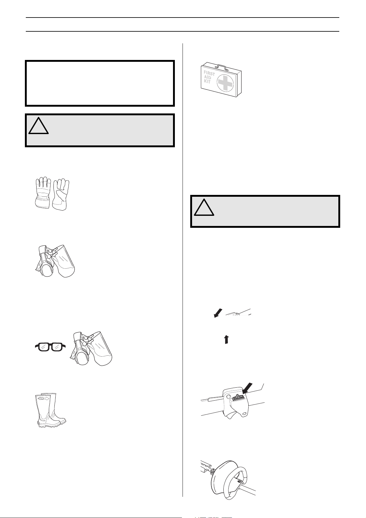
GLOVES
Gloves must be worn when required, for example when fitting,
inspecting or cleaning cutting attachments.
HEARING PROTECTION
Wear hearing protection that provides adequate noise
reduction.
EYE PROTECTION
Always wear approved eye protection. If you use a visor then
you must also wear approved protective goggles. Approved
protective goggles must comply with standard ANSI Z87.1 in
the USA or EN 166 in EU countries. Visors must comply with
standard EN 1731.
FIRST AID KIT
Always have a first aid kit nearby.
Machine
This section describes the machine
purpose, and how checks and maintenance should be carried
out to ensure that it operates correctly. See the ”What is
what?” section to locate where this equipment is positioned
on your machine.
The life span of the machine can be reduced and the risk of
accidents can increase if machine maintenance is not carried
out correctly and if service and/or repairs are not carried out
professionally. If you need further information please contact
your nearest service workshop.
!
′
s safety equipment
′
s safety equipment, its
WARNING! Never use a machine that has
faulty safety equipment! Carry out the
inspection, maintenance and service
routines listed in this section.
Throttle lock
The throttle lock is designed to prevent accidental operation
of the throttle control. When you press the lock (A) (i.e. when
you grasp the handle) it releases the throttle control (B).
When you release the handle the throttle control and the
throttle lock both move back to their original positions. This
movement is controlled by two independent return springs.
This arrangement means that the throttle control is
automatically locked at the idle setting.
BOOTS
Wear sturdy, non-slip boots.
CLOTHING
Wear clothes made of a strong fabric and avoid loose clothing
that can catch on twigs and branches. Always wear heavy,
long pants. Do not wear jewellery, shorts sandals or go
barefoot. Secure hair so it is above shoulder level.
English
4 –
Stop switch
Use the stop switch to switch off the engine.
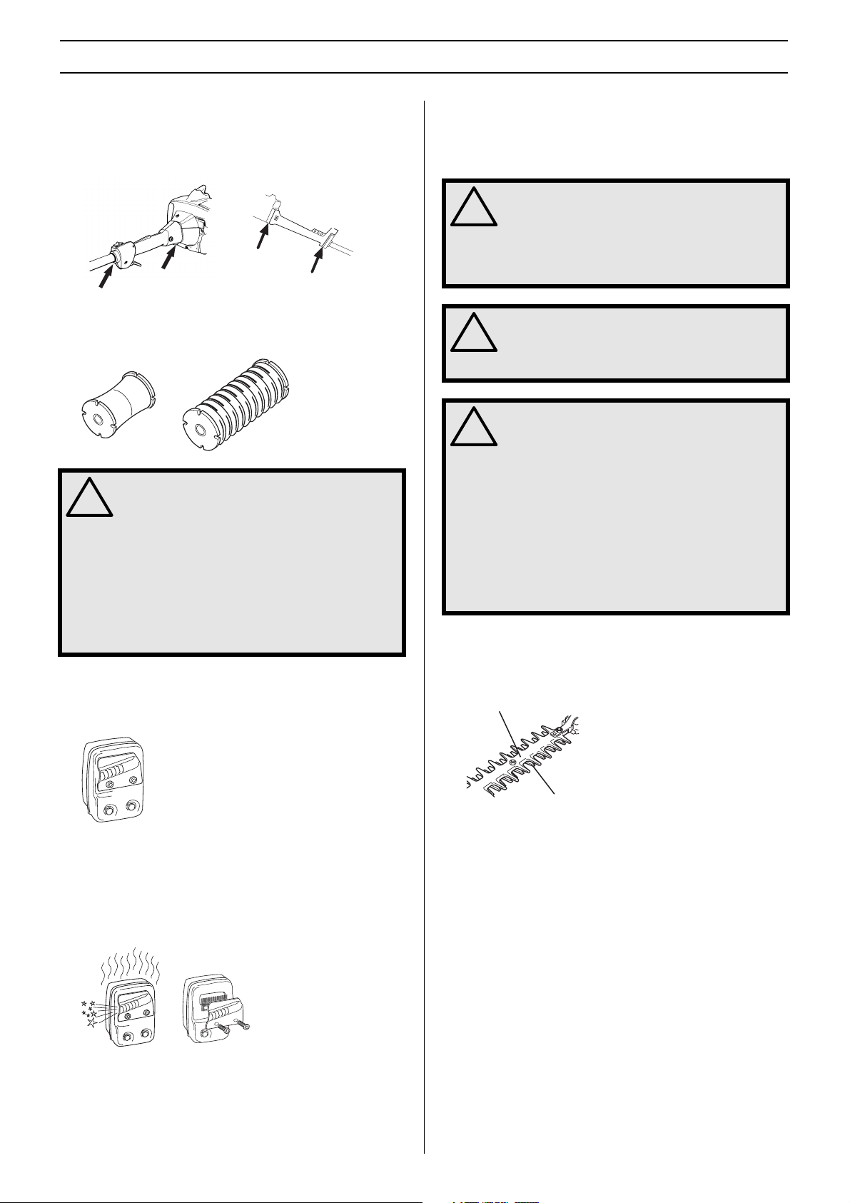
Hand guard (325HDA55,325HE3)
The hand guard prevents hands from coming into contact with
the moving blades, for example, if the operator loses grip on
the front handle.
Page 5
A
B
SAFETY INSTRUCTIONS
Vibration damping system
Your machine is equipped with a vibration damping system
that is designed to minimise vibration and make operation
easier.
The machine
of vibration between the engine unit/cutting equipment and
the machine
!
′
s vibration damping system reduces the transfer
′
s handle unit.
WARNING! Overexposure to vibration can
lead to circulatory damage or nerve damage
in people who have impaired circulation.
Contact your doctor if you experience
symptoms of overexposure to vibration.
Such symptoms include numbness, loss of
feeling, tingling, pricking, pain, loss of
strength, changes in skin colour or
condition. These symptoms normally appear
in the fingers, hands or wrists. The risk
increases at low temperatures.
For mufflers it is very important that you follow the instructions
on checking, maintaining and servicing your machine. See
instructions under the heading Checking, maintaining and
servicing the machine’s safety equipment.
WARNING! Mufflers fitted with catalytic
converters get very hot during use and
!
remain so for some time after stopping. This
also applies at idle speed. Contact can result
in burns to the skin. Remember the risk of
fire!
WARNING! The inside of muffler contain
chemicals that may be carcinogenic. Avoid
!
contact with these elements in the event of a
damaged muffler.
WARNING! Bear in mind that:
!
Engine exhaust fumes contain carbon
monoxide, which can cause carbon
monoxide poisoning. For this reason you
should not start or run the machine indoors,
or anywhere that is poorly ventilated.
The exhaust fumes from the engine are hot
and may contain sparks which can start a
fire. Never start the machine indoors or near
combustible material!
Cutter guard (325HDA55)
Muffler
The muffler is designed to keep noise levels to a minimum
and to direct exhaust fumes away from the user.
A muffler fitted with a catalytic converter is also designed to
reduce harmful exhaust gases.
In countries that have a warm and dry climate there is a
significant risk of fire. We therefore fit certain mufflers with a
spark arrestor mesh. Check whether the muffler on your
machine is fitted with this kind of mesh.
The blade guard (A) is intended to protect against any part of
the body coming into contact with the blades (B).
English
– 5
Page 6
SAFETY INSTRUCTIONS
Checking, maintaining and servicing
the machine
WARNING! All servicing and repair work on
the machine requires special training. This is
!
especially true of the machine
equipment. If your machine fails any of the
checks described below you must contact
your service agent. When you buy any of our
products we guarantee the availability of
professional repairs and service. If the
retailer who sells your machine is not a
servicing dealer, ask him for the address of
your nearest service agent.
WARNING! Never use a machine with faulty
safety equipment. The machine’s safety
!
equipment must be checked and maintained
as described in this section. If your machine
fails any of these checks contact your
service agent to get it repaired.
WARNING! Always stop the engine before
doing any work on the cutting attachment.
!
This continues to rotate even after the
throttle has been released. Ensure that the
cutting attachment has stopped completely
and disconnect the HT lead from the spark
plug before you start to work on it.
Throttle lock
′
s safety equipment
′
s safety
• See instructions under the heading Start. Start the hedge
trimmer and apply full throttle. Release the throttle trigger
and check that the blades stop and remain stationary. If
the blades move when the throttle trigger is in the idle
position then the carburettor idle setting must be adjusted.
See instructions under the heading Maintenance.
Stop switch
• Start the engine and make sure the engine stops when
you move the stop switch to the stop setting.
Hand guard
(325HDA55,325HE3)
• Check that the hand guard is fitted correctly.
• Check that the hand guard is undamaged.
• Make sure the throttle control is locked at the idle setting
when the throttle lock is released.
• Press the throttle lock and make sure it returns to its
original position when you release it.
• Check that the throttle control and throttle lock move freely
and that the return springs work properly.
Vibration damping system
• Regularly check the vibration damping units for cracks or
deformation.
• Check that the vibration damping element is undamaged
and securely attached.
6 –
English
Page 7

SAFETY INSTRUCTIONS
Muffler
• Never use a machine that has a faulty muffler.
• Regularly check that the muffler is securely attached to
the machine.
• If the muffler on your machine is fitted with a spark
arrestor mesh this must be cleaned regularly. A blocked
mesh will cause the engine to overheat and may lead to
serious damage. Never use a muffler with a defective
spark arrestor mesh.
Cutter guard
(325HDA55)
• Check that the blade guard is not damaged or distorted.
• Replace the blade guard if it is bent or damaged.
Gear housing
• The gear housing gets hot when the machine has been in
use. To avoid burning yourself do not touch the gear
housing.
Blades
To ensure good cutting results it is important that the contact
pressure between the blades is correct. The contact pressure
is adjusted by turning the screws on the underside of the bar
clockwise as far as they will go. Then turn the screws
anticlockwise a 1/4 turn. Lock the screws using the locking nut
on the top of the bar. Check that the screws are loose enough
to allow the washers under the screw heads to slide sideways.
When the blades are correctly adjusted the play between the
blades should be 0,2–0,4 mm, measured at the screws.
The edges of the blades are too hard to be filed. Dull blades
should be sharpened using a grinder.
Replace the blades if they are bent or damaged.
English
– 7
Page 8

SAFETY INSTRUCTIONS
General safety precautions
IMPORTANT!
The machine is only designed for cutting branches and
twigs.
Never use the machine if you are tired, if you have drunk
alcohol, or if you are taking medication that could affect your
vision, your judgement or your co-ordination.
Wear personal protective equipment. See instructions
under the heading Personal protective equipment.
Never use a machine that has been modified in any way
from its original specification.
Never use the machine in extreme weather conditions such
as severe cold, very hot and/or humid climates.
Never use a machine that is faulty. Carry out the checks,
maintenance and service instructions described in this
manual. Some maintenance and service measures must be
carried out by trained and qualified specialists. See
instructions under the heading Maintenance.
All covers and guards must be fitted before starting. Make
sure the spark plug cap and HT lead are not damaged.
Otherwise you could get an electric shock.
WARNING! Faulty blades can increase the
risk of accidents.
!
Starting
Fuel safety
• Always use a fuel container with an anti-spill valve.
• Never refuel the machine while the engine is running.
Always stop the engine and let it cool for a few minutes
before refuelling.
• Make sure there is plenty of ventilation when refuelling or
mixing fuel (petrol and 2-stroke oil).
• Move the machine at least 3 m from the refuelling point
before starting it.
• Never start the machine:
1 If you have spilt fuel on it. Wipe off the spillage and allow
remaining fuel to evaporate.
2 If you have spilt fuel on yourself or your clothes, change
your clothes. Wash any part of your body that has come in
contact with fuel. Use soap and water.
3 If the machine is leaking fuel. Check regularly for leaks
from the fuel cap and fuel lines.
4 Avoid all skin contact with fuel. Fuel is a skin irritant and
may even cause skin changes.
• The complete clutch cover and shaft must be fitted before
the machine is started, otherwise the clutch can come
loose and cause personal injury.
• Never start the machine indoors. Exhaust fumes can be
dangerous if inhaled.
• Observe your surroundings and make sure that there is no
risk of people or animals coming into contact with the
cutting equipment.
• Place the machine on the ground, ensure the cutting
attachment is clear of twigs and stones. Hold the body of
the machine on the ground using your left hand
(CAUTION! Not with your foot). Then grip the starter
handle with your right hand and pull the starter cord.
Transport and storage
• Store and transport the machine and fuel so that there is
no risk of any leakage or fumes coming into contact with
sparks or naked flames, for example, from electrical
machinery, electric motors, electrical relays/switches or
boilers.
• When storing and transporting fuel always use approved
containers intended for this purpose.
• When storing the machine for long periods the fuel tank
must be emptied. Contact your local petrol station to find
out where to dispose of excess fuel.
• The transport guard must always be fitted to the cutting
attachment when the machine is being transported or in
storage.
• Ensure the machine is cleaned and that a complete
service is carried out before long-term storage.
8 –
English
Page 9

SAFETY INSTRUCTIONS
Safety instructions when using the
hedge trimmer
WARNING! The machine can cause serious
personal injury. Read the safety instructions
!
carefully. Learn how to use the machine.
WARNING! Cutting tool. Do not touch the
tool without first switching off the engine.
!
CAUTION! Please read the operator’s manual carefully and
make sure you understand the instructions before using the
machine.
Personal protection
Safety instructions while working
• Always ensure you have a safe and stable working
position
• Always use both hands to hold the machine. Hold the
machine at the side of your body.
• Use your right hand to control the throttle setting.
• Always wear boots and other equipment described under
the heading Personal protective equipment.
• Always wear working clothes and heavy-duty long
trousers.
• Never wear loose clothing or jewellery.
• Make sure your hair does not hang below shoulder level.
Safety instructions regarding the
surroundings
• Never allow children to use the machine.
• Ensure that no-one comes closer than 15 m while you are
working.
• Never allow anyone else to use the machine without first
ensuring that they have understood the contents of the
operator’s manual.
• Never work from a ladder, stool or any other raised
position that is not fully secured.
• Make sure that your hands and feet do not come near the
cutting attachment when the engine is running.
• When the engine is switched off, keep your hands and feet
away from the cutting attachment until it has stopped
completely.
• Watch out for stumps of branches that can be thrown out
during cutting.
• Always lay the machine on the ground when you are not
using it.
• Do not cut too close to the ground. Stones and other
objects can be thrown out.
• Check the working area for foreign objects such as
electricity cables, insects and animals, etc, or other
objects that could damage the cutting attachment, such
as metal items.
• If any foreign object is hit or if vibrations occur stop the
machine immediately. Disconnect the HT lead from the
spark plug. Check that the machine is not damaged.
Repair any damage.
• If anything jams in the blades while you are working,
switch off the engine and wait until it has stopped
completely before cleaning the blades. Disconnect the HT
lead from the spark plug.
Safety instructions after completing work
• The transport guard should always be fitted to the cutting
attachment when the machine is not in use.
• Make sure the cutting attachment has stopped before
cleaning, carrying out repairs or an inspection.
Disconnect the HT lead from the spark plug.
English
– 9
Page 10

SAFETY INSTRUCTIONS
• Always wear heavy-duty gloves when repairing the cutting
attachment. This is extremely sharp and can easily cause
cuts.
• Store the machine out of reach of children.
• Use only original spare parts for repairs.
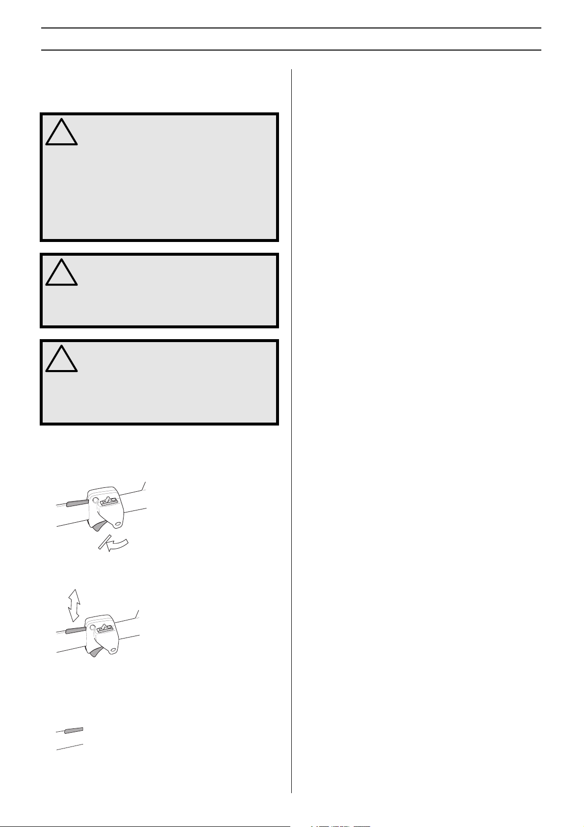
Basic working techniques
• Work with a swinging action from the bottom upwards
when trimming sides.
Changing the hedge trimmer angle
(325HE3,325HE4)
• Undo the knob.
• Grasp the handle on the angle stop, adjust to the desired
angle and then tighten the knob.
• Adjust the throttle setting to suit the load.
• When trimming a hedge the engine should always face
away from the hedge.
• Hold the machine as close to your body as possible to get
the best balance.
• Make sure that the tip does not touch the ground.
• Do not rush the work, but work steadily until all the
branches have been cut back cleanly.
(325HDA55)
• Undo the knob.
• Press the cutting head against the ground or some other
solid object until the desired angle has been obtained.
• Tighten the knob.
10 –
English
WARNING! Do not hold the cutting head
when you adjust the angle. The blades are
!
sharp and you could easily cut yourself.
Page 11

WHAT IS WHAT?
What is what?
English – 11
Page 12

ASSEMBLY
Fitting the hand guard and loop
handle
(325HDA55,325HE3)
1 Assemble the hand guard and loop handle by screwing
them together. Take care to align the holes in both parts.
2 Slide the loop handle and hand guard onto the shaft.
3 Slide the spacer into the slot in the loop handle.
4 Fit the nut and screw. Do not overtighten.
5 Now make a final adjustment to give yourself a
comfortable working position. Tighten the screw.
CAUTION! The loop handle and hand guard must not be
fitted behind the arrow marked on the shaft.
Fitting the cutting head
It is important that the hedge trimmer is laid on a flat surface
when you fit the cutting head. Otherwise the cutting head may
not be fitted straight.
1 Fit the cutting head to the shaft. CAUTION! Make sure the
drive shaft inside the shaft engages with the recess in the
cutting head.
2 Tighten the lower screw first, then the upper screw.
Adjusting the harness
(325HE4)
You should always use the harness with the machine to give
maximum control over the machine and reduce the risk of
fatigue in your arms and back.
1 Put on the harness.
2 Hook the machine onto the harness support hook.
3 Adjust the length of the harness so that the support hook
is roughly level with your right hip.
Fitting the handle
(325HE3,325HE4)
Fit the handle using two screws.
Fitting the impact guard
(325HE4)
Fit the guard using the three screws and washers. Fit the two
short screws in hole A. Tighten the screws to a torque of 4
Nm. After the machine has been in use for around 20 hours,
re-tighten the screws to 4 Nm.
12 – English
Page 13

FUEL HANDLING
Fuel
CAUTION! The machine is equipped with a two-stroke engine
and must always been run using a mixture of petrol and twostroke engine oil. It is important to accurately measure the
amount of oil to be mixed to ensure that the correct mixture is
obtained. When mixing small amounts of fuel, even small
inaccuracies can drastically affect the ratio of the mixture.
Petrol
CAUTION! Always use a good quality petrol/oil mixture (at
least 90 octane). If your machine is equipped with a catalytic
converter (see chapter on Technical data) always use a good
quality unleaded petrol/oil mixture. Leaded petrol will destroy
the catalytic converter and it will no longer serve its purpose.
Use low-emission petrol, also known as alkylate petrol, if it is
available.
• The lowest recommenva79.8(ter (t recommenv)25li.57T*s
en small aca(a)3ol,c reck0t(le)15.1((UTIOir)ualis39.8(n incr09 ed(en small )rok)20(tempe25l/oil mixt, which)10(aresulrolnno lon)25lioustrok)20(e engall )damag-29.8(pose)15-i.57T*s
rol an(v)25.utcata0w[(aousthigharef fue15.thigh5rcommenv)i.57T*s
English – 13
Page 14

STARTING AND STOPPING
Check before starting
• Inspect the working area. Remove any objects that could
be thrown out.
• Check the cutting attachment. Never use blades that are
dull, cracked or damaged.
• Check that the machine is in perfect working order. Check
that all nuts and screws are tight.
• Make sure the gear housing is lubricated correctly. See
instructions under the heading Gear housing.
• Check that the cutting attachment always stops when the
engine is idling.
• Only use the machine for the purpose it was intended for.
• Make sure that the handle and safety features are in good
working order. Never use a machine that lacks a part or
has been modified outside its specifications.
• All covers must be correctly fitted and undamaged before
you start the machine.
Starting and stopping
Starting
WARNING! The complete clutch cover and
gear housing must be fitted before the
!
machine is started, otherwise the clutch may
come loose and cause personal injury.
Always move the machine about 3 metres
from the refuelling position before starting.
Place the machine on a firm surface.
Remember that the blades may start to move
when the engine is started. Make sure the
blades cannot come into contact with any
object. Make sure that no unauthorised
persons are in the working area, otherwise
there is a risk of serious personal injury.
Cold engine
Ignition: Set the stop switch to the start position.
Choke: Set the choke control in the choke position. This
should automatically set the stop switch to the start position.
Air purge: Press the air purge diaphragm repeatedly until
fuel begins to fill the diaphragm. The diaphragm need not be
completely filled.
Warm engine
Ignition: Set the stop switch to the start position.
Choke: Set the throttle to the start position by moving the
choke control to the choke position and then returning it to its
original position.
14 – English
Page 15

STARTING AND STOPPING
Air purge: Press the air purge diaphragm repeatedly until
fuel begins to fill the diaphragm. The diaphragm need not be
completely filled.
Hold the body of the machine on the ground using your left
hand (CAUTION! Not with your foot!).
Grip the starter handle, slowly pull out the cord with your right
hand until you feel some resistance (the starter pawls grip),
now quickly and powerfully pull the cord.
Push the choke control back to its original position as soon as
the engine fires, and continue trying to start until the engine
starts. When the engine starts, quickly apply full throttle to
automatically disengage the start throttle setting.
CAUTION! Do not pull the starter cord all the way out and
do not let go of the starter handle when the cord is fully
extended. This can damage the machine.
Stopping
The engine is stopped by moving the stop switch to the stop
position.
English – 15
Page 16

MAINTENANCE
L
+ 1/4
Carburettor
Your Husqvarna product has been designed and
manufactured to specifications that reduce harmful
emissions. After the engine has used 8-10 tanks of fuel the
engine will be run-in. To ensure that it continues to run at peak
performance and to minimise harmful exhaust emissions
after the running-in period, ask your dealer/service workshop
(who will have a rev counter at their disposal) to adjust your
carburettor.
WARNING! The complete clutch cover and
shaft must be fitted before the machine is
!
started, otherwise the clutch can come loose
and cause personal injury.
Function
• The carburettor governs the engine’s speed via the
throttle control. Air and fuel are mixed in the carburettor.
The air/fuel mixture is adjustable. Correct adjustment is
essential to get the best performance from the machine.
• Adjusting the carburettor means that the engine is
adapted to local operating conditions, e.g. climate,
altitude, petrol and the type of 2-stroke oil.
• The carburettor has three adjustment controls:
L = Low speed jet
H = High speed jet
T = Idle adjustment screw
CAUTION! If the cutting attachment rotates when the engine
is idling the idle adjustment screw T should be turned anticlockwise until the cutting attachment stops.
Rec. idle speed 2700 rpm
Recommended max. speed: See the Technical data section.
WARNING! If the idle speed cannot be
adjusted so that the cutting attachment
!
stops, contact your dealer/service
workshop. Do not use the machine until it
has been correctly adjusted or repaired.
Fine adjustment
• When the machine has been ”run-in” the carburettor
should be finely adjusted. The fine adjustment should be
carried out by a qualified person. First adjust the L-jet,
then the idling screw T and then the H-jet.
Conditions
• Before any adjustments are made, make sure that the air
filter is clean and the air filter cover is fitted. If you adjust
the carburettor when the air filter is dirty it will result in a
leaner mixture when the filter is finally cleaned. This can
lead to serious engine damage.
• Carefully turn both jets, L and H, so that they are midway
between fully screwed in and fully screwed out.
• Do not attempt to adjust the L and H jets beyond either
stop as this could cause damage.
• Now start the machine according to the starting
instructions and let it warm up for 10 minutes.
CAUTION! If the cutting attachment rotates when the engine
is idling the idle adjustment screw T should be turned anticlockwise until the cutting attachment stops.
• The L and H-jets are used to adjust the supply of fuel to
match the rate that air is admitted, which is controlled with
the throttle. If they are screwed clockwise the air/fuel ratio
becomes leaner (less fuel) and if they are turned anticlockwise the ratio becomes richer (more fuel). A lean
mixture gives a higher engine speed and a rich mixture
gives a lower engine speed.
• The T-screw regulates the throttle setting at idle speed. If
the T-screw is turned clockwise this gives a higher idle
speed; turning it anti-clockwise gives a lower idle speed.
Basic setting
• The basic carburettor settings are adjusted during testing
at the factory. The basic setting is richer than the optimal
setting and should be maintained for the first few hours the
machine is in use. The carburettor should then be finely
adjusted. Fine adjustment should be carried out by a
skilled technician.
Low speed jet L
Try to find the highest idle speed by turning the low speed jet
L clockwise then anti-clockwise. When the highest speed has
been found, turn the low speed jet L 1/4 turn anti-clockwise.
CAUTION! If the cutting attachment rotates when the engine
is idling the idle adjustment screw T should be turned anticlockwise until the cutting attachment stops.
Fine adjustment of the idle speed T
Adjust the idle speed with the idle adjustment screw T, if
adjustment is necessary. First turn the idle adjustment screw
T clockwise until the blades start to move. Then turn the idle
adjustment screw T anticlockwise until the blades stop. The
idle speed is correctly adjusted when the engine runs
smoothly in every position. There should also be a clear
margin to the speed at which the blades start to move.
16 – English
Page 17

MAINTENANCE
The blades must also remain stationary when the choke
control is in the start throttle position.
IMPORTANT! If the idle speed cannot be adjusted so that the
cutting attachment stops, contact your dealer/service
workshop. Do not use the machine until it has been correctly
adjusted or repaired.
High speed jet H
The high speed jet H affects the engine power, speed,
temperature and fuel consumption. If the high speed jet H is
set too lean (screwed in too far) the engine speed will be too
high and cause engine damage. Do not let the engine run at
full speed for more than 10 seconds.
Correctly adjusted carburettor
When the carburettor is correctly adjusted the machine
accelerates without hesitation and burbles a little at maximum
speed. It is also important that the blades do not move when
the engine is idling or when the choke control is in the start
position. If the low speed jet L is set too lean it may cause
starting difficulties and poor acceleration.
If the high speed jet H is set too lean it will result in less power,
less performance, poor acceleration and/or damage to the
engine. If both the L and H jets are set too rich it will results in
acceleration problems or too low a working speed.
Muffler
CAUTION! Some mufflers are fitted with a catalytic converter.
See chapter on Technical data to see whether your machine
is fitted with a catalytic converter.
The muffler is designed to reduce the noise level and to direct
the exhaust gases away from the operator. The exhaust
gases are hot and can contain sparks, which may cause fire
if directed against dry and combustible material.
Apply full throttle and turn the high speed jet H very slowly
clockwise until the engine slows down. Then turn the high
speed jet H very slowly anticlockwise until the engine starts to
run unevenly. Now turn the high speed jet H slowly clockwise
a little way until the engine runs smoothly.
Note that the engine should not be under load when you
adjust the high speed jet H. You should therefore remove the
cutting attachment, nut, support flange and drive disc before
adjusting the high speed jet H. The high speed jet H is
adjusted correctly when the machine burbles a little. If the
machine races then the setting is too lean. If the engine
produces a lot of smoke and burbles a lot then the setting is
too rich.
H
CAUTION! For optimum adjustment of the carburettor,
contact a qualified dealer/service workshop that has a
revolution counter at their disposal.
Some mufflers are equipped with a special spark arrestor
mesh. If your machine has this type of muffler, you should
clean the mesh at least once a week. This is best done with a
wire brush.
On mufflers without a catalytic converter the mesh should be
cleaned weekly, or replaced if necessary. On mufflers fitted
with a catalytic converter the mesh should be checked, and if
necessary cleaned, monthly. If the mesh is damaged it
should be replaced. If the mesh is frequently blocked, this
can be a sign that the performance of the catalytic converter
is impaired. Contact your dealer to inspect the muffler. A
blocked mesh will cause the machine to overheat and result
in damage to the cylinder and piston. See also instructions
under the heading Maintenance.
CAUTION! Never use a machine with a defective muffler.
WARNING! Mufflers fitted with catalytic
converters get very hot during use and
!
remain so for some time after stopping. This
also applies at idle speed. Contact can result
in burns to the skin. Remember the risk of
fire!
English – 17
Page 18

MAINTENANCE
Cooling system
To keep the working temperature as low as possible the
machine is equipped with a cooling system.
4
3
2
1
The cooling system consists of:
1 Air intake on the starter.
2 Fins on the flywheel.
3 Cooling fins on the cylinder.
4 Cylinder cover (directs cold air over the cylinder).
Clean the cooling system with a brush once a week, more
often in demanding conditions. A dirty or blocked cooling
system results in the machine overheating which causes
damage to the piston and cylinder.
Spark plug
The spark plug condition is influenced by:
• Incorrect carburettor adjustment.
• An incorrect fuel mixture (too much or incorrect type of
oil).
• A dirty air filter.
These factors cause deposits on the spark plug electrodes,
which may result in operating problems and starting
difficulties.
If the machine is low on power, difficult to start or runs poorly
at idle speed: always check the spark plug first before taking
any further action. If the spark plug is dirty, clean it and check
that the electrode gap is 0.5 mm. The spark plug should be
replaced after about a month in operation or earlier if
necessary.
Air filter
The air filter must be regularly cleaned to remove dust and dirt
in order to avoid:
• Carburettor malfunctions
• Starting problems
• Loss of engine power
• Unnecessary wear to engine parts.
• Excessive fuel consumption.
Clean the filter every 25 hours, or more regularly if conditions
are exceptionally dusty.
Cleaning the air filter
Remove the air filter cover and take out the filter. Wash it
clean in warm, soapy water. Ensure that the filter is dry before
refitting it.
An air filter that has been in use for a long time cannot be
cleaned completely. The filter must therefore be replaced with
a new one at regular intervals. A damaged air filter must
always be replaced.
If the machine is used in dusty conditions the air filter should
be soaked in oil. See instructions under the heading Oiling the
air filter.
Oiling the air filter
Always use HUSQVARNA filter oil, art. no. 531 00 92-48. The
filter oil contains a solvent to make it spread evenly through
the filter. You should therefore avoid skin contact.
Put the filter in a plastic bag and pour the filter oil over it.
Knead the plastic bag to distribute the oil. Squeeze the
excess oil out of the filter inside the plastic bag and pour off
the excess before fitting the filter to the machine. Never use
common engine oil. This would drain through the filter quite
quickly and collect in the bottom.
CAUTION! Always use the recommended spark plug type!
Use of the wrong spark plug can damage the piston/cylinder.
Check that the spark plug is fitted with a suppressor.
18 – English
Page 19

MAINTENANCE
1
3
5
67 8 9
4
Gear housing
There are three grease nipples on the gear housing. Use a
grease gun to top up with grease. This should be carried out
approximately every 20 working hours. Use Husqvarna
special grease, part no. 503 98 96-01.
CAUTION! The gear housing must not be filled completely
with grease. The grease expands as the machine heats up
during operation. If the gear housing was completely filled
with grease it could damage the seals and lead to leakage of
grease.
The grease in the bevel gear does not normally need to be
changed except if repairs are carried out.
Cleaning and lubrication
After you have used the machine clean any resin and plant
residue from the blades using cleaning agent 531 00 60-75
(UL22).
Always lubricate the blade bars with special grease, part no.
531 00 60-74 (UL 21) before use.
5 Clean the air filter. Replace if necessary.
6 Check that the hand guard is not damaged. Replace the
guard if damaged.
7 Check that nuts and screws are tight.
8 Check that there are no fuel leaks from the engine, tank or
fuel lines.
Weekly maintenance
1 Check the starter and starter cord.
2 Check that the vibration damping elements are not
damaged.
3 Clean the outside of the spark plug. Remove it and check
the electrode gap. Adjust the gap to 0.5 mm or replace the
spark plug. Check that the spark plug is fitted with a
suppressor.
4 Clean the cooling fins on the flywheel.
5 Clean or replace the spark arrestor mesh on the muffler
(only applies to mufflers without a catalytic converter).
6 Clean the carburettor compartment.
7 Clean the cooling fins on the cylinder and check that the
air intake near the starter is not blocked.
8 Fill the gear housing with grease. This should be carried
out approximately every 20 working hours.
9 Check that the screws that hold the blades together are
correctly tightened.
Maintenance schedule
Below you will find some general maintenance instructions. If
you need further information please contact your service
workshop.
Daily maintenance
1
5
1 Clean the outside of the machine.
2 Check that the components of the throttle control work
safely. (Throttle lock and throttle control.)
3 Check that the stop switch works correctly.
4 Check that the blades do not move when the engine is
idling or when the choke is in the start throttle position.
23
6
7
4
Monthly maintenance
1 Clean the fuel tank.
2 Clean the outside of the carburettor and the space around
it.
8
3 Clean the fan and the area around it.
4 Check the fuel filter and the fuel hose. Replace if
necessary.
5 Check all cables and connections.
6 Check the clutch, clutch springs and the clutch drum for
wear. Replace if necessary.
7 Replace the spark plug. Check that the spark plug is fitted
with a suppressor.
8 Check and clean the spark arrestor mesh on the muffler
(only applies to mufflers fitted with a catalytic converter).
English – 19
Page 20

TECHNICAL DATA
Technical data
Technical data 325HDA55 325HE3 325HE4
Engine
Cylinder displacement, cm
Cylinder bore, mm 34 34 34
Stroke, mm 27 27 27
Idle speed, rpm 2700 2700 2700
Recommended max. speed, rpm 9500-10500 9500-10500 9500-10500
Max. speed;should not be exceded, rpm 10800 10800 10800
Max. engine output, acc. to ISO 8893 0,9/9000 0,9/9000 0,9/9000
Catalytic converter muffler Yes Yes Yes
Speed-regulated ignition system Yes Yes Yes
Ignition system
Manufacturer/type of ignition system WalbroMB/SEM AM49 WalbroMB/SEM AM49 WalbroMB/SEM AM49
Spark plug NGK BPMR 7A NGK BPMR 7A NGK BPMR 7A
Electrode gap, mm 0,5 0,5 0,5
Fuel and lubrication system
Manufacturer/type of carburettor Zama C1Q Zama C1Q Zama C1Q
Fuel tank capacity, litre 0,5 0,5 0,5
Weight
Weight without fuel, cutting attachment and guard, kg 5,5 5,7 5,8
Noise emissions
(see note 1)
Sound power level, measured dB(A) 105 104 105
Sound power level, guaranteed L
Noise levels
(see note 2)
Equivalent noise pressure level at the operator’s ear,
measured according to EN/ISO 11806 and ISO 7917,
dB(A), min./max.: 92 93 91
Vibration levels
Vibration levels at handles, measured according to
EN/ISO 11806 and ISO 7916, m/s
Idle speed, rear/front handles: 3,5/1,8 3,8/1,4 2,2/1,8
Max. speed, rear/front handles: 3,1/5,7 4,7/5,5 7,5/6,6
Blades
Length, mm 550 550 550
Blade speed, cuts/min 4184 4184 4184
3
dB(A) 105 105 105
WA
2
24,5 24,5 24,5
Note 1: Noise emissions in the environment measured as sound power (LWA) in conformity with EC directive 2000/14/EC.
Note 2: Equivalent sound pressure level is calculated as the time-weighted energy total for sound pressure levels under various
working conditions with the following time distribution: 1/2 idling and 1/2 max speed.
20 – English
Page 21

TECHNICAL DATA
EC-declaration of conformity (Applies to Europe only)
Husqvarna AB, SE-561 82 Huskvarna, Sweden, tel: +46-36-146500, declare under sole responsibility that the hedge trimmers
Husqvarna 325HDA55, 325HE3 and 325HE4 from 2002’s serial numbers and onwards (the year is clearly stated in plain text on
the type plate with subsequent serial number), are in conformity with the standards or or other normative documents following the
provisions in the COUNCIL’S DIRECTIVES:
of June 22, 1998 ”relating to machinery” 98/37/EC, annex IIA.
of May 3, 1989 ”relating to electromagnetic compatibility” 89/336/EEC, and applicable supplements.
of May 8, 2000 ”relating to the noise emissions in the environment” 2000/14/EC.
For information relating to noise emissions, see the chapter Technical data. The following standards have been applied: EN292-2,
CISPR 12:1997, EN774
SMP Svensk Maskinprovning AB, Fyrisborgsgatan 3, SE-754 50 Uppsala, Sweden, has carried out voluntary type approval for
Husqvarna AB. The certificates have the numbers: SEC/00/789, 01/094/001 - 325HDA55, SEC/00/790, 01/094/002 - 325HE3,
SEC/00/791, 01/094/001 - 325HE4
Huskvarna January 3, 2002
Bo Andréasson, Development manager
English – 21
Page 22

´®z+H1^¶6[¨
1140176-26
´®z+H1^¶6[¨
2003-07-07
Page 23

We hope you find the links below useful. For further gardening information visit
Gardening Tools Direct
Blower Vacs Brush cutters Brushcutters Chainsaws Chain saws
Cultivators Cylinder lawn
mowers
Electric
chainsaws
Garden tractors Garden vacuums Hayter lawn
Hover mowers Husqvarna
Lawn scarifiers Lawn tractors Leaf blowers Leaf vacuums Petrol chainsaws
Petrol hedge
cutters
Ryobi strimmers Scarifiers Strimmers Westwood lawn
Westwood
Fertiliser
spreaders
chainsaws
Ride on lawn
mowers
Cylinder mowers Echo chainsaws Echo Strimmers
Garden blowers Garden rollers Garden shredders
Hedge cutters
mowers
Kawasaki brush
cutters
Ride on mowers Rotary mowers Rotavators
tractors
Kawasaki
strimmers
tractors
He dgecutters
Lawn mowers
Westwood ride on
mowers
 Loading...