

Page 1
RYOBI
_________________
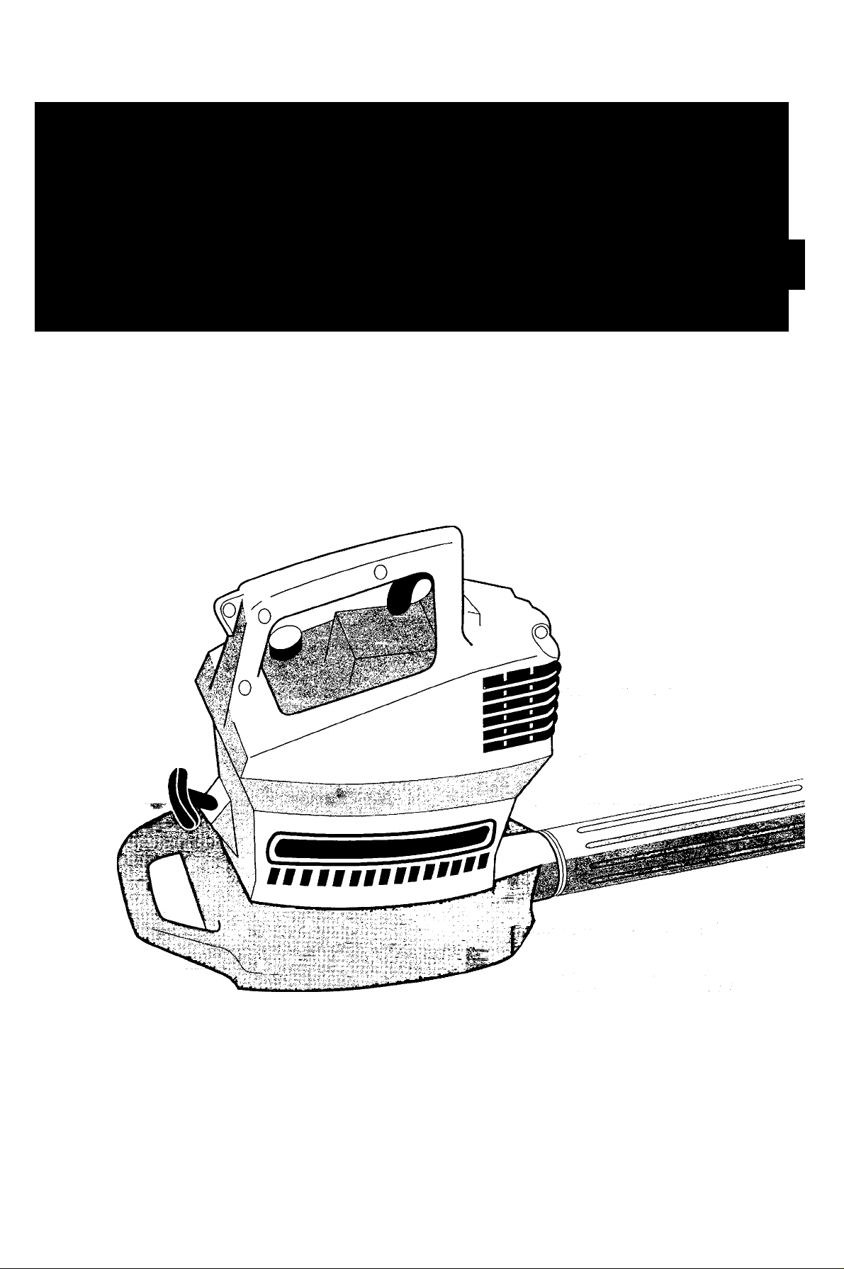
2-Cycle Gas 280r Blower or 310BVr BlowerIVacuum
280r!310BVr____________________
OPERATOR'S MANUAL
IMPORTANT MANUAL
FOR QUESTIONS, CALL 1-800-345-8746 in U.S. or
1-800-668-1238 in CANADA
www.RyobiOutdoor.com
DO NOT THROW AWAY
Page 2

INTRODUCTION
TABLE OF CONTENTS
THANK YOU
Thank you for buying this quaiity product. This modern
outdoor power tooi will provide many hours of usefui
service. You will find it to be a great iabor-saving device.
This operator’s manual provides you with easy-tounderstand operating instructions. Read the whoie
manual and follow all the instructions to keep your new
outdoor power tool in top operating condition.
PRODUCT REFERENCES, ILLUSTRATIONS, AND
SPECIFICATIONS
All information, illustrations, and specifications in this
manual are based on the latest product information
available at the time of printing. We reserve the right to
make changes at any time without notice.
Copyright ©2001 MTD SOUTHWEST INC
All Rights Reserved.
SERVICE INFORMATION
Service on this unit both within and after the warranty
period should be performed only by an authorized and
approved service dealer.
Dial:
• 1-800-345-8746 orwww.RyobiOutdoor.com on
the World Wide Web for authorized service dealers in
the United States
Or
• 1-800-668-1238 in Canada to obtain the listing of
the authorized service dealer nearest you.
DO NOT RETURN THE UNIT TO THE RETAILER.
NOTE: PROOF OF PURCHASE WILL BE REQUIRED
FOR WARRANTY SERVICE.
Make sure this manual is carefully
read and understood before starting
or operating this equipment.
I. California Proposition 65 Warning .............................. 3
II. Rules for Safe Operation.......................................... 3-7
A. Important Safety Information
B. Safety and International Symbols
C. Know Your Unit
III. Assembly Instructions
A. Blower Tube and Nozzle Assembly
B. Installing the Vacuum Bag/Tube Assembly
(Model 31 OBVr only) ............................................. 8
C. Installing the Adapter onto
the Upper Vacuum Tube (Model 31 OBVr only) 9
D. Assembling the Vacuum Tubes
(Model 31 OBVr only)
E. Installing the Complete Vacuum Tube Assembly
to the BlowerA/acuum (Model 31 OBVr only) .. 10
F. Installing and Adjusting the
Shoulder Strap (Model 31 OBVr only) ................. 11
IV. Oil and Fuel Information
V. Starting/Stopping Instructions
VI. Operating Instructions
A. Holding the BlowerA/acuum
B. Operating Tips....................................................... 14
C. Blower Operating Procedures............................... 14
D. Vacuum Operating Procedures
(Model 31 OBVr only) ........................................... 15
VII. Maintenance and Repair Instructions
A. Maintenance Schedule
B. Air Filter Maintenance
C. Spark Arrestor Maintenance
D. Carburetor Adjustment .................................... 18-19
E. Replacing the Spark Plug
F Accessories/Replacement Parts
G. Cleaning
H. Storage ................................................................. 20
I. Long Term Storage
VIII. Troubleshooting Chart
IX. Specifications ............................................................ 22
X. Warranty..................................................................... 24
.......................................................
............................................
............................................
..........................................
................................................................
...............................................
...............................
........................
.................
.........................................
...................................
................................
.................
........................................
......................................
............................
....................................
............................
.......................................
4-5
5-6
8-11
8
10
12
13
14-15
14
15-20
15
15-16
17-18
19
19
20
20
21
7
THIS PRODUCT IS COVERED BY ONE OR MORE
U.S. PATENTS. OTHER PATENTS PENDING.
A complete parts list can be viewed and printed
by going to our web site:
Or,
you can request a copy by calling 1-800-345-TRVM
(1 -800-345-8746). Please have the unit model and
serial number when calling.
www.RyobiOutdoor.com
CONTENTS OF CARTON
• Model 280r Blower or Model 31 OBVr Blower/Vacuum
Model 280r includes:
•Blower Tubes
Model 31 OBVr Blower/Vacuum includes:
• Blower/Vacuum Tubes
• Vacuum Bag/Strap and Adapter
• Shoulder Strap
• Operator's Manual
• Product Registration Card
• Bottle of Ryobi 2-Cycle Oil
Examine all parts to make certain that nothing is missing
and no breakage has occurred during shipping. Any
damaged part must be replaced before using this product.
Page 3

CALIFORNIA PROPOSITION 65 WARNING:
A
THE ENGINE EXHAUST FROM THIS
PRODUCT CONTAINS CHEMICALS
KNOWN TO THE STATE OF CALIFORNIA
TO CAUSE CANCER, BIRTH DEFECTS,
OR OTHER REPRODUCTIVE HARM.
NOTE: For users on U.S. Forest Land and in the states of California, Maine, Oregon, and Washington. All U.S. Forest
Land and the state of California (Public Resources Codes 4442 and 4443), Oregon, and Washington require by law that
certain internal combustion engines operated on forest brush and/or grass-covered areas be equipped with a spark
arrestor, maintained in effective working order, or the engine be constructed, equipped, and maintained for the prevention
of fire. Check with your state or local authorities for regulations pertaining to these requirements. Failure to follow these
requirements could subject you to liability or a fine. This unit is factory equipped with a spark arrestor. If it requires
replacement, ask your LOCAL SERVICE DEALER to install the Accessory Part #182747 Spark Arrestor,
WARNING
SPARK ARRESTOR
A
Read the Operator’s Manual(s) and follow all warnings and safety instructions. Failure to do so can result in serious injury to the operator and/or bystanders.
FOR QUESTIONS, CALL 1 >800-345-8746 in U.S. OR 1-800-668-1238 in CANADA
RULES FOR SAFE OPERATION
The purpose of safety symbols is to attract your
attention to possible dangers. The safety symbols and
their explanations deserve your careful attention and
understanding. The safety warnings do not by
themselves eliminate any danger. The instructions or
warnings they give are not substitutes for proper
accident prevention measures.
SYMBOL MEANING
SAFETY ALERT SYMBOL: Indicates
A
NOTE: Advises you of information or instructions
danger, warning, or caution. Attention is
required in order to avoid serious personal
injury. May be used in conjunction with
other symbois or pictographs.
vital to the operation or maintenance of the
equipment.
A
A
A
DANGER: Failure to obey a safety warning
will result In serious Injury to yourself or to
others. Always follow the safety precautions
to reduce the risk of fire, electric shock, and
personal Injury.
WARNING; Failure to obey a safety warning
can result in injury to yourself and others.
Always follow the safety precautions to
reduce the risk of fire, electric shock, and
personal Injury.
CAUTION: Failure to obey a safety warning
may result in property damage or personal
injury to yourself or to others. Always follow
the safety precautions to reduce the risk cf
fire, electric shcck, and perscnal injury.
Page 4

RULES FOR SAFE OPERATION
IMPORTANT SAFETY INFORMATION
READ ALL INSTRUCTIONS
WARNING: When using the unit, the safety
A
BEFORE OPERATING
• Read the instructions carefully. Be familiar with the
controls and proper use of the unit.
• Do not operate this unit when tired, ill, or under the
influence of alcohol, drugs, or medication.
• Children and teens under the age of 15 must not use
the unit, except for teens guided by an adult.
• All guards and safety attachments must be installed
properly before operating the unit.
• Inspect the unit before use. Replace damaged parts.
Check for fuel leaks. Make sure all fasteners are in
place and secure. Replace parts that are cracked,
chipped, or damaged in any way. Do not operate the
unit with loose or damaged parts.
• Carefully inspect the area before starting the unit.
Remove all debris and hard or sharp objects such as
glass, wire, etc.
• Clear the area of children, bystanders, and pets. At a
minimum, keep all children, bystanders, and pets
outside a 50 feet (15 m.) radius; there still may be a risk
to bystanders from thrown objects. Bystanders should
be encouraged to wear eye protection. If you are
approached, stop the unit immediately.
SAFETY WARNINGS FOR GAS UNITS
WARNING: Gasoline is highly flammable, and its vapors
can explode if ignited. Take the following precautions:
• Store fuel only in containers specifically designed and
• Avoid creating a source of ignition for spilled fuel. Do
• Always stop the engine and allow it to cool before filling
• Mix and add fuel in a clean, well-ventilated area outdoors
• Move the unit at least 30 feet (9.1 m) from the fueling
rules must be followed. For your own safety
and that of bystanders, please read these
instructions before operating the unit. Please
keep the instructions safe for later use.
approved for the storage of such materials.
not start the engine until fuel vapors dissipate.
the fuel tank. Never remove the cap of the fuel tank, or
add fuel, when the engine is hot. Never operate the unit
without the fuel cap securely in place. Loosen the fuel
tank cap slowly to relieve any pressure in the tank.
where there are no sparks or flames. Slowly remove the
fuel cap only after stopping engine. Do not smoke while
fueling or mixing fuel. Wipe up any spilled fuel from the
unit immediately. Always wipe unit dry before using.
source and site before starting the engine. Do not
smoke or allow sparks and open flames near the area
while adding fuel or operating the unit.
WHILE OPERATING
• Never start or run the unit inside a closed room or
building. Breathing exhaust fumes can kill. Operate this
unit only in a well-ventilated area outdoors.
• To reduce the risk of injury associated with thrown
objects, wear safety glasses or goggles that are
marked as meeting ANSI Z87. standards.
• Never run the unit without the the proper equipment
attached. When using this unit, always install the
blower/vacuum tubes and vacuum bag depending on
model. Make sure the vacuum bag is completely
zipped closed.
• To reduce the risk of hearing loss associated with
sound level(s), always wear ear/hearing protection
when operating this unit.
• Wear heavy, long pants, boots, and gloves. Do not
wear short pants, sandals, or go barefoot.
• To avoid static electricity shock, do not wear rubber
gloves or any other insulated gloves while operating
this unit.
• To reduce the risk of injury associated with objects
being drawn into rotating parts, do not wear loose
clothing, jewelry, scarves, and the like. Secure hair
above shoulder level.
• Wear a face or dust mask if the operation is dusty.
Long sleevfe shirts are recommended.
• Use the unit only in daylight or good artificiai light.
• Keep outside surfaces free from oil and fuel.
• Avoid accidental starting. Be in the starting position
whenever pulling the starter rope. The operator and
unit must be in a stable position while starting. See
Starting/Stopping
• Do not set unit on any surface except a clean, hard
area while engine Is running. Debris such as gravel,
sand, dust, grass, etc. could be picked up by the air
intake and thrown out by the discharge opening,
damaging unit, property, or causing serious injury to
bystanders or operator.
• Use the right tool. Only use this tool for the purpose
intended.
• Do not force unit. It will do the job better and with less
likelihood of injury at a rate for which it was designed.
• Do not overreach or use from unstabie surfaces such
as ladders, trees, steep slopes, rooftops, etc. Always
keep proper footing and balance.
• Always hold the unit with a firm grip when operating.
• Keep hands, face, and feet at a distance from all moving
parts. Do not touch or try to stop the impeller when it is
rotating. Do not operate without guards in place.
• Do hot put any object into openings. Do not use with
any opening blocked; keep free of dirt, debris, and
anything that may reduce the air flow.
instructions.
Page 5

RULES FOR SAFE OPERATION
• Do not touch the engine or muffler. These parts get
extremely hot from operation. When turned off they
remain hot for a short time.
• Do not operate the engine faster than the speed
needed to do the job. Do not run the engine at high
speed when not in use.
• Always stop the engine when operation is delayed or
when walking from one location to another.
• Stop the engine for maintenance, repair, to install or
remove the blower tubes or vacuum attachments.
The unit must be stopped and the impeller no longer
turning to avoid contact with the rotating blades.
• Use only genuine Ryobi® replacement parts when
servicing this unit. These parts are available from
your authorized service dealer. Do not use parts,
accessories, or attachments not authorized by
Ryobi® for this unit. Doing so could lead to serious
injury to the user, or damage to the unit, and void
your warranty.
• Never use this unit for spreading chemicals,
fertilizers, or other substances which may contain
toxic materials.
• To reduce fire hazard, replace faulty muffler and spark
arrestor, keep the engine and muffler free from grass,
leaves, excessive grease, or carbon build up.
WHILE OPERATING UNIT AS A BLOWER
• Never point the blower in the direction of people or
pets, or in the direction of windows. Always direct the
blowing debris away from people, animals, and
windows. Use extra caution when blowing debris near
solid objects such as trees, automobiles, walls, etc.
WHILE OPERATING UNIT AS A VACUUM
(Model 310BVr Only)
• Avoid situations that could catch the vacuum bag
on fire. Do not operate near an open flame. Do not
vacuum warm ash from fireplaces, barbecue pits,
brush piles, etc. Do not vacuum discarded cigars or
cigarettes unless the cinders are completely cool.
• The unit is designed to pickup dry material such as
leaves, grass, small twigs, and bits of paper. Do not
attempt to vacuum wet debris and/or standing water
as this may result in damage to the blower/ vacuum.
To avoid severe damage to the impeller, do not
vacuum metal, broken glass, etc.
OTHER SAFETY WARNINGS
• Always disconnect the spark plug before performing
maintenance or accessing movable parts.
• Never store the unit, with fuel in the tank, inside a
building where fumes may reach an open flame (pilot
lights, etc.) or sparks (switches, electrical motors, etc.).
• Allow the engine to cool before storing or transporting.
Be sure to secure the unit while transporting.
• Store the unit in a dry place, either locked up or up
high to prevent unauthorized use or damage. Keep out
of the reach of children.
• Never douse or squirt the unit with water or any other
liquid. Keep handles dry, clean, and free from debris.
Clean after each use, see Cleaning and Storage
instructions.
• Keep these instructions. Refer to them often and use
them to instruct other users. If you loan this unit to
others, also loan these instructions to them.
SAVE THESE INSTRUCTIONS
SAFETY AND INTERNATIONAL SYMBOLS
This operator's manual describes safety and international symbols and pictographs that may appear on this product.
Read the operator's manual for complete safety, assembly, operating, maintenance, and repair information.
SYMBOL
A
• SAFETY ALERT SYMBOL
Indicates danger, warning, or caution. May be used in conjunction with other
symbols or pictographs.
• WARNING - READ OPERATOR'S MANUAL
Read the Operator’s Manual(s) and follow ail warnings and safety instructions.
Failure to do so can result in serious injury to the operator and/or bystanders.
MEANING
Page 6
RULES FOR SAFE OPERATION
SYMBOL MEANING
• WEAR EYE AND HEARING PROTECTION
WARNING: The operation of any power tool can be the source of thrown objects
and loud noise which can cause severe eye injury and hearing loss. Always wear
safety glasses or goggles eye protection meeting ANSI Z87.1 standards and ear
protection when operating this unit. Use a full face shield when needed.
• KEEP BYSTANDERS AWAY
(ISm)
5-7x
WARNING: Keep all bystanders, especially children and pets, at least 50 feet
(15 m) from the operating area.
• PRIMER BULB
Push primer bulb, fully and slowly, 5 to 7 times.
UNLEADED FUEL
Always use clean, fresh unleaded fuel.
OIL
Refer to operator's manual for the proper type of oil.
• THROWN OBJECTS AND ROTATING CUTTER CAN CAUSE SEVERE
INJURY
WARNING: Do not operate without the guard in place.
Keep away from the rotating cutter.
ABC
H N |f|
• HOT SURFACE WARNING
Do not touch a hot muffler, gear housing, or cylinder. You may get burned. These
parts get extremely hot from operation. When turned off they remain hot for a
short time.
CHOKE CONTROL
A • FULL choke position.
B • PARTIAL choke position.
C • RUN position.
• BLOWERS AND BLOWER/VACUUMS - ROTATING IMPELLER BLADES
CAN CAUSE SEVERE INJURY
WARNING: Stop the engine and allow the impeller to stop before installing or
changing tubes or bag, or before cleaning or performing any maintenance.
Page 7
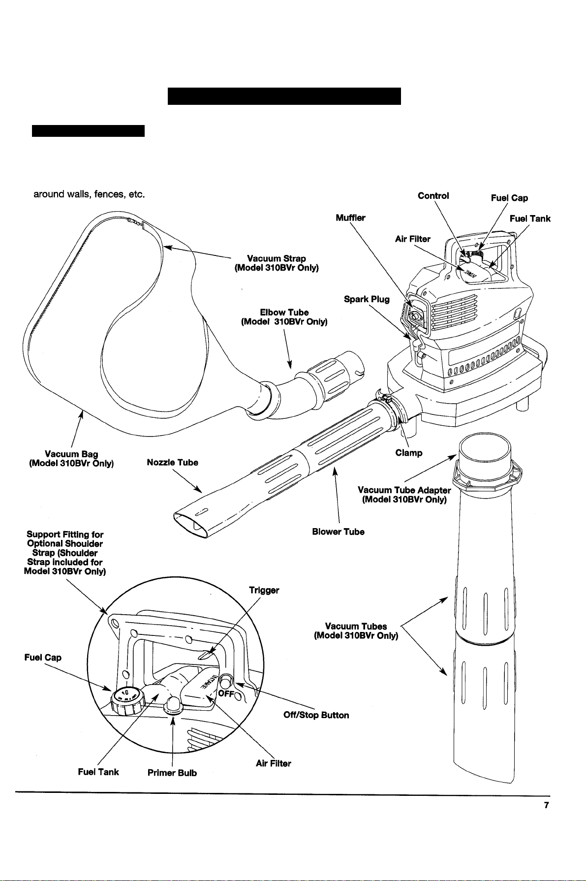
KNOW YOUR UNIT
RULES FOR SAFE OPERATION
APPLICATIONS
Models 280r and 310BVr - As a BLOWER:
• Cleaning yards, garages, driveways, porches, patios.
Model 310BVr only - As a VACUUM:
• Picking up ieaves, iight debris, etc.
Throttle
Page 8
ASSEMBLY INSTRUCTIONS
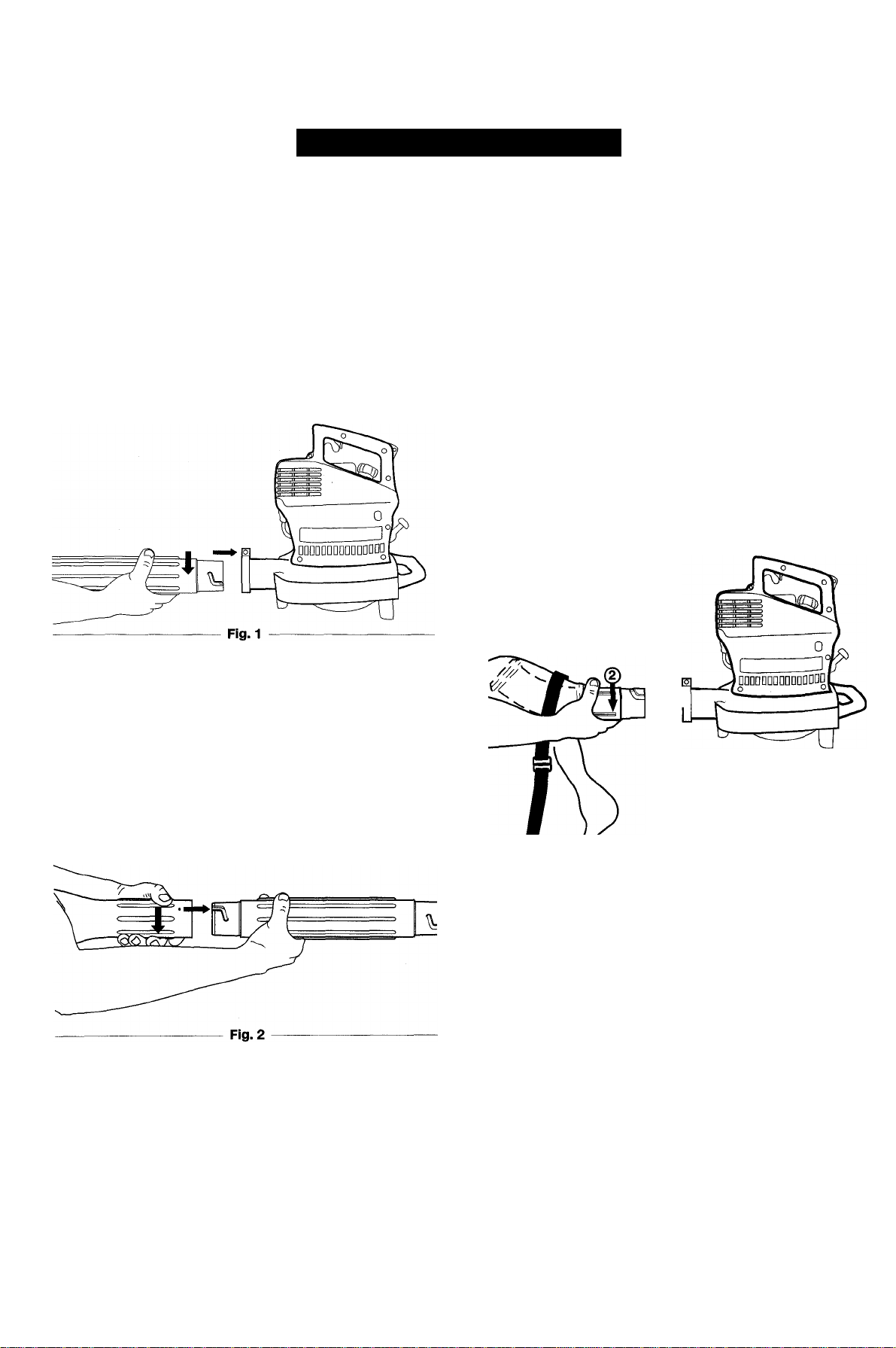
BLOWER TUBE AND NOZZLE ASSEMBLY
WARNING: Do not install tubes while unit is
running to avoid serious personal injury.
A
1. Align the grooves in the blower tube with the pins in
the blower outlet.
2. Grasping the tube firmly with both hands, push the
tube into the blower outlet (Fig. 1). Turn the tube
clockwise until it snaps into the detent and locks.
INSTALLING THE VACUUM BAG/TUBE
ASSEMBLY (MODEL 310BVr ONLY)
WARNING: Rotating impeller blades can
cause severe injury. Do not attempt to
A
1. Remove the blower tubes.
2. Align the grooves in the vacuum bag/elbow tube
3. Grasping the tube firmly with both hands, push the
convert the unit while the engine is running
to avoid serious personal injury. Do not put
hands or any other object into the vacuum
tubes while they are installed on the unit.
assembly with the pins in the blower outlet.
vacuum bag/elbow tube assembly into the blower
outlet (Fig. 3). Turn the assembly clockwise until it
snaps into the detent and locks. The curve of the
adapter tube should angle upwards.
3. Align the pins of the blower nozzle with the grooves
in the blower tube (Fig. 2).
4. Grasping the nozzle firmly with both hands, push the
nozzle onto the blower tube. Turn the nozzle
clockwise until it snaps into the detent and locks.
NOTE: The blower tube and nozzle or vacuum bag
(Model 310BVr only) must be used at all times to
prevent overheating the engine.
(3>
Fig.3
Page 9

ASSEMBLY INSTRUCTIONS
INSTALLING THE ADAPTER ONTO THE UPPER
VACUUM TUBE (MODEL 310BVr ONLY)
WARNING: Do not install while unit is
running to avoid serious personal injury.
A
1. Turn the blower upside down (Fig. 4). Hold the blower
between your knees to install the adapter and
vacuum tubes.
2. Locate the hole in the door. The door lock tab is
recessed in the hole (Fig. 5). Press the door lock tab
toward the front of the unit (away from the handle) to
release the lock and open the door (Fig. 6).
3. Align the adapter's three (3) slots with the unit's three
(3) hooks (Fig. 6). Push firmly so all three (3) hooks
snap through (Fig. 7).
4. Align the arrow on the upper vacuum tube with the
arrow on the adapter. Slide the upper vacuum tube
onto the adapter (Fig. 8).
NOTE: The arrows must align properly to install the
vacuum tubes correctly.
Hooks (3)
Fig. 6
Fig. 5
Fig. 7
Fig. 8
Page 10

ASSEMBLY INSTRUCTIONS
5. Grasping the upper vacuum tube firmly with both hands
(Fig. 9), turn the vacuum tube clockwise (Fig. 10) until
the two (2) tabs of the adapter snap into the two (2)
square indentations of the upper vacuum tube (Fig. 11).
NOTE: This assembly requires the use of both hands
because the parts fit together tightly.
NOTE: The flat area on the upper vacuum tube should face
the handle as you install the vacuum tube (Fig. 13).
NOTE: When the tabs lock into the indentations, the
adapter and vacuum tube become a permanent
assembly. The adapter can no longer be
removed from the vacuum tube.
ASSEMBLING THE VACUUM TUBES
(MODEL 310BVr ONLY)
WARNING: Do not install the vacuum tubes
A
1. Align the arrow on the lower vacuum tube with the
2. Grasping the lower vacuum tube firmly with both
while unit is running to avoid serious
personal injury.
arrow on the upper vacuum tube (Fig. 12).
hands, push the lower vacuum tube into the upper
vacuum tube. Turn the lower vacuum tube clockwise
until it snaps into detent and locks. (The dot on the
lower tube aligns with the dot on the upper tube
when properly assembled.)
Fig. 9
Fig. 10
Adapter
Fig. 12
INSTALLING THE COMPLETE VACUUM TUBE
ASSEMBLY TO THE BLOWER/VACUUM
(MODEL 310BVr ONLY)
WARNING: Do not install the vacuum tubes
A
1. Grasp the assembled vacuum tube firmly with both
NOTE: When the tube is installed correctly, the flat on
while unit is running to avoid serious
personal injury.
hands. Turn the tube/adapter clockwise as far as
possible to the end of the grooves until It snaps into
the detent and locks (Fig. 13).
the upper tube faces the handle on the
blower/vac (Fig. 13).
Lower Vac Tube
10
Fig. 11
t
11
r
__
Fig. 13
Page 11

ASSEMBLY INSTRUCTIONS
INSTALLING AND ADJUSTING THE SHOULDER STRAP (MODEL 310BVr ONLY)
WARNING: Always use the shoulder
A
1. Push the strap through the center of the buckle.
2. Pull the strap over the cross bar and down through
3. Fully extend the strap.
---------------------------------------------Fig. 14-----------------------------------------
strap when using the vacuum (Model 31 OBVr
only) to avoid serious personal injury.
NOTE: Have the shoulder strap on and adjusted, but not
clipped to the support fitting prior to starting unit.
the slot in the buckle (Fig. 14).
5. Place the strap over your head and onto your
shoulders (Fig. 16).
Fig. 16
6. While standing in the operating position (Fig.16)
adjust length to fit the operator’s size.
• Lengthen the strap by pulling down on the strap and
lifting the buckle end up (Fig. 17).
• Shorten the strap by pulling the strap down through
the buckle while holding the buckle (Fig. 17).
4. Attach the metal clip of the shoulder strap to the
support fitting on the back of the handle (Fig. 15).
Support Fitting on
Metal Clip
Shoulder
Strap
Fig. 15
Back of Handle
Fig. 17
11
Page 12

OIL AND FUEL INFORMATION
OIL AND FUEL MIXING INSTRUCTIONS
Old and/or improperly mixed fuel are the main reasons
for the unit not running properly. Be sure to use fresh,
clean unleaded fuel. Follow the instructions carefully for
the proper fuel/oil mixture.
Definition of Blended Fuels
Today's fuels are often a blend of gasoline and
oxygenates such as ethanol, methanol, or MTBE (ether).
Alcohol-blended fuel absorbs water. As little as 1 % water
in the fuel can make fuel and oil separate. It forms acids
when stored. When using alcohol-blended fuel, use fresh
fuel (less than 60 days old).
Using Blended Fuels
If you choose to use a blended fuel, or its use is
unavoidable, follow recommended precautions.
• Always use fresh fuel mix per your operator's manual.
• Always agitate the fuel mix before fueling the unit.
• Drain the tank and run the engine dry before storing
the unit.
Using Fuei Additives
The bottle of Ryobi 2-Cycle Oil that came with your unit
contains a fuel additive which will help inhibit corrosion
and minimize the formation of gum deposits. It is
recommended that you use only Ryobi 2-Cycle Oil with
this unit.
If unavailable, use a good 2-cycle oil designed for
air-cooled engines along with a fuel additive, such as
STA-BIL® Gas Stabilizer or an equivalent. Add 0.8 oz.
(23 ml.) of fuel additive per gallon of fuel according to the
instructions on the container. NEVER add fuel additives
directly to the unit's fuel tank.
Thoroughly mix the proper ratio of 2-cycle engine oil with
unleaded gasoline in a separate fuel can. Use a 32:1
fuel/oil ratio. Do not mix them directly in the engine fuel
tank. See the table below for specific gas and oil mixing
ratios.
NOTE: One gallon (3.8 liters) of unleaded gasoline mixed
with one 4 oz. (120 ml.) bottle of Ryobi
2-Cycle Oil makes a 32:1 fuel/oil ratio.
UNLEADED GAS
WARNING: Gasoline is extremely
A
flammable. Ignited vapors may explode.
Always stop the engine and allow it to cool
before filling the fuel tank. Do not smoke
while filling the tank. Keep sparks and open
flames at a distance from the area.
1 US. GALLON + 4.0 FL. OZ.
(3.8 LITERS) (120 ml)
1 LITER + 30 ml
MIXING RATIO - 32:1
RYOBI 2 CYCLE OIL
A
12
CAUTION: For proper engine operation and
maximum reliability, pay strict attention to
the oil and fuel mixing instructions on the 2cycle oil container. Using improperly mixed
fuel can severely damage the engine.
WARNING: Remove fuel cap slowly to avoid
A
A
NOTE: Dispose of the old fuel/oil mix in accordance to
injury from fuel spray. Never operate the unit
without the fuel cap securely in place.
WARNING: Add fuel in a clean, well-
ventilated area outdoors. Wipe up any spilled
fuel immediately. Avoid creating a source of
ignition for spilled fuel. Do not start the
engine until fuel vapors dissipate.
Federal, state, and local regulations.
Page 13

STARTING/STOPPING INSTRUCTIONS
STARTING INSTRUCTIONS
WARNING: Operate this unit oniy in a weii-
ventiiated area outdoors. Carbon monoxide
A
A
1. Mix gas with oil. Fill fuel tank with fuel/oil mixture.
A
exhaust fumes can be iethai in a confined area.
__ ^-------------------------------------------------------------------------
WARNING: Avoid accidentai starting. Be in
the starting position when puiiing the starter
rope (Fig. 20 for blower, Fig. 21 for vacuum).
The operator and unit must be in a stabie
position whiie starting to avoid serious
personai injury.
Aiso, do not set unit on any surface except a
ciean, hard area whiie starting. Debris such
as gravel, sand, dust, grass, etc. could be
picked up by the air intake and thrown out
by the discharge opening, damaging unit,
property, or causing serious injury to
bystanders or operator.
See Oil and Fuel Mixing Instructions on page 12.
WARNING: Model SIOBVr only: To avoid
serious personal injury, always remove the
vacuum bag prior to refueling the unit. The
bag may become a fire hazard when
saturated with fuel.
Primer
Bulb
/
FULL CHOKE
POSITION
Throttle
Control
Stop/Off
Button
Fig. 18
PARTIAL CHOKE
POSITION
RUN
POSITION
2. Fully press and release primer bulb slowly 5 to 7 times.
Fuel should be visible in the bulb (Fig. 18). If fuel is not
visible, press three (3) more times, or until it is.
3. Place the choke lever in the FULL choke (j-^)
position (Fig. 19).
4. Place the unit in the starting position (Fig. 20 for blower.
Fig. 21 for vacuum).
5. Squeeze the throttle control to the wide open (full
throttle) position (Fig. 18). Pull the starter rope briskly
5 times while still in the FULL choke (H) position. If
the engine attempts to run before the fifth pull,
proceed to Step 6.
NOTE: The engine will not run in the FULL choke (H)
position.
6. Place the choke lever in the PARTIAL choke (|\|)
position (Fig. 19).
7. Pull starter rope briskly 1 to 3 times to start the
engine (Fig. 20 for blower. Fig. 21 for vacuum).
NOTE: Squeeze the throttle control until the engine has
started and warmed up.
8. If the engine does not start, repeat steps 4 through 7.
NOTE: If the engine floods while trying to start, place the
choke lever in the RUN (Ml) position (Fig. 19).
Pull the starter rope briskly. The engine should
start with three (3) to eight (8) pulls.
Fig. 21
STOPPING INSTRUCTIONS
To stop the engine, push and hold the stop button until
the engine comes to a complete stop (Fig. 18).
NOTE: To prevent vapor lock, avoid setting the unit in
the sun.
13
Page 14

OPERATING INSTRUCTIONS
HOLDING THE BLOWER/VACUUM
Before operating the unit, stand in the operating position.
Check for the following:
• Operator is wearing proper clothing, such as boots,
safety glasses or goggles, ear/hearing protection,
gloves, long pants, and long sleeve shirt.
WARNING: To avoid serious personal injury,
A
• If the conditions are dusty, a dust mask or face mask is
being worn.
• The unit is in good working condition.
• The tubes and guards are in place and secure.
A
wear goggles or safety glasses at all times
when operating this unit. Wear a face mask
dust mask in dusty locations.
or
WARNING: To prevent serious personal injury
to yourself or others, or damage to the unit,
make sure blower tubes or vacuum tubes and
vacuum bag are in place, depending on the
model, before operating the unit.
• Watch out for children, pets, open windows, or freshly
washed cars, and blow debris safely away.
• Use the full blower nozzle extension so the air stream
can work close to the ground.
• After using blowers and other equipment, CLEAN UP!
Dispose of debris in trash receptacles.
BLOWER OPERATING PROCEDURES
1 Use the blower for trees, shrubs, flower beds and
hard-to-clean areas (Fig. 22).
2. Use the unit around buildings and for other normal
cleaning (Fig. 22).
3. Use the blower for walls, overhangs, fences, and
screens (Fig. 23).
OPERATING TIPS
• Assure the unit is not directed at loose debris or
persons before starting unit.
• Be sure the unit is in good working condition. Make
sure the tubes and guards are in place and secure.
• It is recommended holding the unit with both hands
when operating the blower at waist level or at awkward
angles (Fig. 23).
• To reduce the risk of hearing loss associated with sound
level(s), the use of hearing protection is required.
• Operate power equipment only at reasonable hours—
not early in the morning or late at night when people
might be disturbed. Comply with times listed in local
ordinances. Usual recommendations are 9:00 am to
5:00 pm, Monday through Saturday.
• To reduce noise levels, limit the number of pieces of
equipment used at any one time.
• To reduce noise levels, operate power blowers at the
lowest possible speed to do the job.
• Check your equipment before operation, especially the
muffler, air intakes, and air filters.
• Use rakes and brooms to loosen debris before blowing.
• In dusty conditions, slightly dampen surfaces or use a
mister attachment when water is available.
• Conserve water by using power blowers instead of
hoses for many lawn and garden applications,
including areas such as gutters, screens, patios, grills,
porches, and gardens.
m
Fig. 23
14
Page 15

OPERATING INSTRUCTIONS
VACUUM OPERATING PROCEDURES
(MODEL 310BVr ONLY)
WARNING: DO NOT OPEN THE DOOR
A
NOTE: Do not wear rubber or any other insulated gloves
NOTE: Be sure the vacuum bag is zipped closed before
1. Move the unit slowly back and forth over the debris
2. Vacuum a large pile of debris working from the
3. Empty the collection bag after each use. Shake the
WITH THE ENGINE RUNNING! To do so can
result in serious personal injury caused by
contact with the rotating biades.
to avoid static electricity shock.
operating the unit.
to be vacuumed (Fig. 24).
outside of the pile. Do not force the suction tube into
the debris because this can clog the tube.
bag vigorously while emptying to remove dust from
the bag, which can block the proper amount of air
flow and deteriorate the performance of the vacuum.
NOTE: Use the zipper when emptying the collection
bag. Do not empty the bag through the nozzle.
Fig. 24
MAINTENANCE AND REPAIR INSTRUCTIONS
NOTE; Some maintenance procedures may require
special tools or skills. If you are unsure about
these procedures, take your unit to an authorized
service dealer.
MAINTENANCE SCHEDULE
These required maintenance procedures should be
performed at the frequency stated in the table. They
should also be included as part of any seasonal tune-up.
FREQUENCY
Before Starting Engine
Every 10 Hours
Every 25 Hours
WARNING: CLEAN AND RE-OIL THE AIR
A
FILTER EVERY 10 HOURS OF OPERATION.
Your unit's air filter is one of the most
important areas to maintain. If it is not
maintained as follows, you will void the
warranty.
MAINTENANCE REQUIRED REFER TO:
Fill fuel tank with correct oil and fuel mixture
Clean and re-oil air filter
Check spark arrestor condition and clean
Check spark plug condition and gap
WARNING: To prevent serious injury, never
A
AIR FILTER MAINTENANCE
Removing the Air Filter Cover
A
do maintenance or repairs with unit running.
Always do maintenance and repairs on a
cool unit. Disconnect spark plug wire to
ensure the unit will not start.
WARNING: To avoid serious personal
injury, always turn the unit off and allow it
to cool before you clean or perform any
maintenance on it.
Page 12
Page 15
Page 17
Page 19
15
Page 16

MAINTENANCE AND REPAIR INSTRUCTIONS
1. Grasp the air filter cover and press in with your
thumb to release. Remove the cover from the air filter
base (Fig. 25).
2. Turn the air filter cover over and remove the air filter
from the inside (Fig. 26).
3. Wash the filter in detergent and water (Fig. 27). Rinse
the filter thoroughly. Squeeze out excess water and
allow it to dry completely.
4. Apply enough clean SAE 30 oil to lightly coat the filter
(Fig. 28).
5. Squeeze the filter to spread the oil and remove the
excess (Fig. 29).
6. Carefully reinstall the air filter. Be sure the filter is
seated properly before reinstalling it on the air filter
base (Fig. 30).
16
Fig. 29
Fig. 26
Fig. 30
Page 17

MAINTENANCE AND REPAIR INSTRUCTIONS
SPARK ARRESTOR MAINTENANCE
Removing the Muffler
WARNING: Make sure the muffler is cool
before removing it from the housing to
A
prevent serious personal injury.
1 Remove the 10 screws holding the unit housing
together with a T20 Torx or flat blade screwdriver
(Fig. 31).
2. Locate the two (2) muffier mounting bolts that are
holding the heat shield and muffler to the engine.
Remove the two (2) bolts using a flat blade
screwdriver or 5/16-inch socket or nut driver (Fig. 32).
NOTE: Do not remove the heat shield/muffler screw to
separate the top heat shield from the muffler.
The spark arrestor will be accessible without
removing the screw.
3. Locate the four (4) screws holding the top heat shield
to the bottom heat shield (two on each side). Remove
the four (4) screws using a T20 Torx or flat blade
screwdriver (Fig. 32).
4. Remove the top heat shield with the muffler attached
from the engine as one piece.
Removing the Spark Arrestor
5. Turn the heat shield/muffler unit over. Look inside the
heat shield and locate the exhaust gasket on the
muffler. Remove the exhaust gasket from the muffler
to locate the spark arrestor (Fig. 33).
NOTE: If exhaust gasket is torn or damaged, replace
with a new gasket before reassembling.
Fig. 32
Fig. 33
6. Using a small flat blade screwdriver, carefully pry up
the spark arrestor from the recessed hole in the
muffler. Remove spark arrestor from muffler (Fig 34).
7. Clean the spark arrestor with a wire brush. Replace if
damaged or unable to clean thoroughly (Fig. 34).
Spark
Muffler
Arrestor
Small Flat Blade Screwdriver
Fig. 34-----------------------------------------------
Spark
Arrestor
17
Page 18

MAINTENANCE AND REPAIR INSTRUCTIONS
8. Place heat shield/muffler on a flat, stable surface with
the heat shield facing down. Reinstall the spark
arrestor by pressing it into the recessed hole in the
muffler. Make sure it fits tightly against the muffler
and is not raised up, bent, or wrinkled once in place.
9. Pick up the unit. If necessary, align muffler bolt holes
with the bolt holes in heat shieid. Insert muffler
mounting boits into holes of heat shield and through
the muffler.
10. Place heat shield/muffler on a flat, stable surface with
the heat shield facing down. Place exhaust gasket
over bolts sticking through the muffier and on top of
the spark arrestor (Fig. 33).
11. Hold heat shield/muffler with finger over the exhaust
gasket to keep it in place. Turn over and align boits
with boit holes in the engine. Push bolts into the
engine hoies and reiease gasket once bolts are
started. Do not tighten bolts completely.
12. Reinstall four (4) screws to attach top heat shield to
bottom heat shield.
13. Tighten muffler mounting bolts.
14. Reassemble the housing unit. Reaiign the two
housing units and screw holes. Make sure all wires
and other parts are completeiy within the housing
units and are not crimped, pinched, or sticking out.
Reinstall the 10 screws.
WARNING: This unit wiii need to be running
during idle speed adjustment. Wear
A
initial Idle Speed Setting
2. Remove the air filter cover and insert a screwdriver
protective clothing and observe all safety
instructions to prevent serious personal injury.
Do not set unit on any surface except a clean,
hard area while starting or performing any
adjustments. Debris such as gravel, sand,
dust, grass, etc. could be picked up by the air
intake and thrown out by the discharge
opening, damaging unit, property, or causing
serious injury to bystanders or operator.
through the opening in the air filter base (Fig. 35).
CARBURETOR ADJUSTMENT
NOTE: Careless adjustments can seriously damage
your unit. An authorized service dealer should
make carburetor adjustments.
Check Fuel Mixture
Old and/or improperly mixed fuel is usually the reason
for the unit not running properly. Drain and refill the tank
with fresh, properly mixed fuei prior to making any
adjustments. Refer to Oil and Fuel Information, Pg. 12.
Clean Air Filter
The condition of the air filter is important to the
operation of the unit. A dirty air filter will restrict air flow
and change the air/fuel mixture. This is often mistaken
for an out of adjustment carburetor. Check the condition
of the air filter before adjusting the idle speed adjuster.
Refer to Air Fiiter Maintenance Pg. 15.
Adjusting the Carburetor
If after checking the fuel mixture and cieaning the air
fiiter the engine stiii will not idle, adjust the idle speed as
follows.
1. Make the initial settings with the engine stopped.
These initial settings should allow you to start and
warm up the unit before making the final adjustments.
--------------------------------------------Fig. 35
3. Back the idle speed screw (Fig. 36) out
(counterclockwise) until it does not contact the
carburetor throttle lever. Then turn the screw in
(clockwise) until it just begins to move the throttle
lever; then continue turning for 2 more full turns.
Throttle
Lever
Idle Speed
Mixture
Needle
-------------------------------------------
Idle Speed
Screw
High Speed
Mixture
Needle
18
Fig. 36
Page 19

MAINTENANCE AND REPAIR INSTRUCTIONS
Initial High Speed Mixture and Idle Speed Mixture
Needle Settings
4. Insert a small flat blade screwdriver through the hole
at the back of the top handle (Fig. 37). Turn both the
high speed mixture and idle speed mixture needles
out (counterclockwise) until the limiter caps stop.
--------------------------------------------
5. Start the engine and let it run for a minute.
6. Release the throttle trigger and let the engine idle. If
the engine stops, turn the idle speed screw (Figs. 35
and 36) in (clockwise) 1/8 turn at a time (as required)
until the engine idles.
NOTE; Forcing the limiter caps with a screwdriver will
damage the needle tips and the seat in the
carburetor body.
Fig. 37
-------------------------------------------------
REPLACING THE SPARK PLUG
Use a Champion RDJ7Y spark plug (or equivalent).
The correct air gap is 0.020 Inch (0.5 mm). Remove the
plug after every 25 hours of operation and check its
condition.
1. Stop the engine and allow it to cool. Grasp the spark
plug wire cap firmly and pull it from the spark plug.
2. Clean around the spark plug. Remove the spark plug
from the cylinder head by turning a 5/8 in. socket
counterclockwise.
3. Replace a cracked, fouled, or dirty spark plug. Set
the air gap at 0.020 In. (0.5 mm) using a feeler gauge
(Fig. 38).
CAUTION: Do not sand blast, scrape, or
A
4. Install a correctly gapped spark plug in the cylinder
If using a torque wrench torque to:
110-120 ln.*lb. (12.3-13.5 N*m).
Do not over tighten.
clean electrodes. Grit in the engine could
damage the cylinder.
head. Tighten by turning the 5/8 inch socket
clockwise until snug.
Final Idle Speed Screw and Idle Speed Mixture
Needle Settings
Adjust the idle speed screw and idle speed mixture
needle for smoothest engine idle.
7. Turn the idle speed mixture needle (Fig. 36) in
(clockwise) until you hear the fastest idle; then turn
the needle out (counterclockwise) 1/8 turn.
8. Squeeze the throttle trigger. If the engine falters or
hesitates as it accelerates, turn the idle speed mixture
needle (Fig. 36) out (counterclockwise) 1/16 turn at a
time until the engine accelerates rapidly.
9. If the idle speed changes significantly because of
Steps 7 and 8, readjust the idle speed screw (refer to
Steps 1 through 3).
Final High Speed Mixture Needle Adjustment
The factory presets the high speed mixture needle at 1-
1/4 turns out from the closed position. Your unit should
perform well at this setting. If additional adjustment of
the high speed mixture needle is required, contact your
local authorized service dealer.
NOTE: High speed mixture needle adjustment is not
recommended without a precision high speed
tachometer.
0.020 in.
(0.5 mm)
--------------------------------------------Fig. 38--------------------------------------------------
ACCESSORIES/REPLACEMENT PARTS
2-Cycle Oil
Sparkplug
Exhaust Gasket........................................................181521
Spark Arrestor...........................................................182747
Fuel Cap.................................................................... 180000
Vacuum Bag Assembly (Model 310BVr only) ... .180490
Shoulder Strap..........................................................682075
These replacement parts can be purchased from your
local authorized dealer.
...............................................................
................................................................
147543
610311
19
Page 20

MAINTENANCE AND REPAIR INSTRUCTIONS
CLEANING
WARNING: To avoid serious personai injury,
A
Use a small brush to clean off the outside of the unit.
Do not use strong detergents. Household cleaners that
contain aromatic oils such as pine and lemon, and
solvents such as kerosene, can damage plastic housing
or handle. Wipe off any moisture with a soft cloth.
STORAGE
• Never store the unit with fuel in the tank where fumes
may reach an open flame or spark.
• Allow the engine to cool before storing.
• Store the unit locked up to prevent unauthorized use or
damage.
• Store the unit in a dry, well-ventilated area.
• Store the unit out of the reach of children.
LONG TERM STORAGE
If the unit will be stored for an extended time, use the
following storage procedure.
1. Drain all fuel from the fuel tank and drain into a
2. Start the engine and allow it to run until it stalls.
3. Allow the engine to cool. Remove the spark plug
always turn your unit off and allow it to cool
before you clean or do any maintenance on it.
container with the same 2-cycle fuel mixture. Do not
use fuel that has been stored for more than 60 days.
Dispose of the old fuel/oil mix in accordance to
Federal, state, and local regulations.
This ensures that all fuel has been drained from the
carburetor.
and put 1 oz. (30 ml) of any high quality motor oil or
2-cycle oil into the cylinder. Pull the starter rope
slowly to distribute the oii. Reinstali the spark plug.
NOTE: Remove the spark plug and drain all of the oil
from the cylinder before attempting to start the
unit after storage.
4. Thoroughly clean the unit and inspect for any loose
or damaged parts. Repair or replace damaged parts
and tighten loose screws, nuts, or bolts. The unit is
ready for storage.
TRANSPORTING
• Allow the engine to cool before transporting.
• Secure the unit while transporting.
• Drain fuel from unit.
• Tighten fuel cap before transporting.
20
Page 21

ENGINE WILL NOT START
TROUBLESHOOTING
CAUSE
Choke in incorrect position
Empty fuei tank
Primer buib wasn't pressed enough
Engine fiooded
Oid or improperiy mixed fuei Drain gas tank / Add fresh fuel mixture
Fouied spark piug
Plugged spark arrestor Clean or replace spark arrestor
ENGINE WILL NOT IDLE
CAUSE ACTION
Air fiiter is piugged
Old or improperly mixed fuel Drain gas tank / Add fresh fuel mixture
Improper carburetor adjustment
ENGINE WILL NOT ACCELERATE
CAUSE ACTION
Old or improperly mixed fuel Drain gas tank / Add fresh fuel mixture
ACTION
Refer to Starting/Stopping instructions on page 13
Fill fuel tank with properly mixed fuel
Press primer bulb fully and slowly 5-7 times until fuel
is visible in the bulb
Use starting procedure WITHOUT USING CHOKE
Replace or clean the spark plug
Replace or clean the air filter
Adjust per instructions on page 18
Improper carburetor adjustment
Throttle wire has come loose Thread throttle wire through the carburetor throttle
Dirty air filter
Plugged spark arrestor Clean or replace spark arrestor
ENGINE LACKS POWER OR STALLS
CAUSE ACTION
Old or improperly mixed fuel
Air filter is plugged
Improper carburetor adjustment
Fouled spark plug
Plugged spark arrestor
Take to an authorized service dealer for
carburetor adjustment
lever. Tighten screw.
Clean or replace the air filter
Drain gas tank / Add fresh fuel mixture
Replace or clean the air filter
Take to an authorized service dealer for
carburetor adjustment
Replace or clean the spark plug
Clean or replace spark arrestor
If further assistance is required, contact your authorized service dealer.
21
Page 22

SPECIFICATIONS
ENGINE
Type......................................................................................................................................................2-Cycle, Air-Cooled
Displacement ...........................................................................................................................................................31 cc (1.9 cu. in)
Bore......................................................................................................................................................................1.37 in (34.79 mm)
Stroke ...................................................................................................................................................................1.25 in (31.75 mm)
Operating RPM ............................................................................................................................................................... 7,200-7,500
Ignition ..................................................................................................................................................................Eiectronic ignition
Lubrication .............................................................................................................................................................Fuel/Oil Mix (32:1)
Carburetor.....................................................................................................................................................Diaphragm, All Position
Ignition Switch................................................................................................................................................................Push Button
Starter.............................................................................................................................................................................
Muffler..................................................................................................................................................................Baffled With Guard
Clutch ........................................................................................................................................................................................ None
Throttle
Bearings.........................................................................................................................................................................Needle & Ball
Crankshaft.................................................................................................................................................................... .Cantilevered
Connecting Rod ...........................................................................................................................................................................Steel
Fuel Tank............................................................................................................................................................
Fuel Tank Capacity...................................................................................................................................................18 fl. oz (532 ml)
Spark Plug
...
.................................................................
.......................................................................................................
....
...............
....
............................
...............................Manual Spring Return
...............
...............................110-120 in«lb (12.3-13.5 N»m)
Auto Rewind
Clear Sight
Max. Blower Velocity
Max. Blower Volume
Operating Weight .......................................................................................................................................................12 lbs (5.22 kg)
Vacuum Bag Capacity
.........................................................................................................................................
........................................................................................................................................
...................................................................................................
....
............................
180 mph (290 kmh)
400 cfm (11.33 cmm)
1.4 bushels (0.066m®)
22
Page 23

23
Page 24

MANUFACTURER’S LIMITED WARRANTY FOR:
RYOBI
The limited warranty set forth below is given by MTD
SOUTHWEST INC (“MTD”) with respect with new
merchandise purchased and used in the United States, its
possessions and territories.
MTD warrants this product against defects in materiai and
workmanship for a period of two (2) years commencing on the
date of originai purchase and wili, at its option, repair or
repiace, free of charge, any part found to be defective in
material or workmanship. This iimited warranty shall only apply
if this product has been operated and maintained in
accordance with the Operator’s Manual furnished with the
product, and has not been subject to misuse, abuse,
commercial use, neglect, accident, improper maintenance,
alteration, vandalism, theft, fire, water or damage because of
other peril or natural disaster. Damage resuiting from the
installation or use of any accessory or attachment not
approved by MTD for use with the product(s) covered by this
manual will void your warranty as to any resulting damage.
This warranty is limited to ninety (90) days from the date of
original retail purchase for any MTD product that is used for
rentai or commercial purposes, or any other incomeproducing purpose.
HOW TO OBTAIN SERVICE: Warranty service is avaiiabie,
WITH PROOF OF PURCHASE THROUGH YOUR LOCAL
AUTHORIZED SERVICE DEALER. To locate the dealer in your
area, please check for a listing in the Yeilow Pages or contact
the Customer Service Department of MTD SOUTHWEST INC
by calling 1-800-345-8746 or writing to 550 N. 54th Street,
Chandier, Arizona 85226 or if in Canada call 1-800-668-1238.
No product returned directly to the factory will be accepted
unless prior written permission has been extended by the
Customer Service Department of MTD SOUTHWEST INC.
This limited warranty does not provide coverage in the
foilowing cases:
A. Tune-ups - Spark Plugs, Carburetor Adjustments, Filters
B. Wear items - Bump Knobs, Outer Spoois, Cutting Line,
Inner Reels, Starter Pulley, Starter Ropes, Drive Belts
C. MTD does not extend any warranty for products sold or
exported outside of the United States of America, its
possessions and territories, except those soid through
MTD’s authorized channeis of export distribution.
MTD reserves the right to change or improve the design of
any RYOBI® Product without assuming any obiigation to
modify any product previousiy manufactured.
®
No implied warranty, including any implied warranty of
merchantability or fitness for a particular purpose,
applies after the applicabie period of express written
warranty above as to the parts as identified. No other
express warranty or guaranty, whether written or oral,
except as mentioned above, given by any person or
entity, including a dealer or retailer, with respect to any
product shali bind MTD. During the period of the
Warranty, the exclusive remedy is repair or replacement
of the product as set forth above. (Some states do not
allow limitations on how iong an impiied warranty iasts, so
the above iimitation may not appiy to you.)
The provisions as set forth in this Warranty provide the
sole and exclusive remedy arising from the sales. MTD
shall not be liable for incidental or consequential loss or
damages including, without limitation, expenses
incurred for substitute or replacement lawn care
services, for transportation or for reiated expenses, or
for rental expenses to temporarily replace a warranted
product. (Some states do not aliow limitations on how iong
an implied warranty lasts, so the above limitation may not
appiy to you.)
In no event shall recovery of any kind be greater than the
amount of the purchase price of the product sold. Alteration
of the safety features of the product shall void this Warranty.
You assume the risk and liability for loss, damage, or injury to
you and your property and/or to others and their property
arising out of the use or misuse or inability to use the product.
This limited warranty shaii not extend to anyone other than
the originai purchaser, originai lessee, or the person for
whom it was purchased as a gift.
How State Law Relates to this Warranty: This warranty
gives you specific iegal rights, and you may also have other
rights which vary from state to state.
To iocate your nearest service deaier diai
1-800-345-8746 in the United States or
1 -800-668-1238 in Canada.
RYOBI® is a registered trademark of Ryobi Limited.
MTD SOUTHWEST INC
550 N. 54th Street
Chandler, AZ 85226 U.S.A.
SAVE THESE INSTRUCTIONS FOR FUTURE REFERENCE.
FOR QUESTIONS CALL 1-800-345-8746 IN U.S.
OPERATOR’S MANUAL PART NO. 10745
PRINTED IN U.S.A.
OR 1-800-668-1238 IN CANADA
REV. A
10/01
 Loading...