

Page 1
EDP2521L
N197
EDP2521L
DRILL PRESS
OWNERʼS OPERATION MANUAL
Page 2

TABLE OF CONTENTS
Page 1
Table of Contents
Specicatons
Rules for Safe Operation
Unpacking
Loose Parts List
Assembly
Adjustment
Operation
Maintenance
Troubleshooting
1
1
2-5
6
6
7
8-9
9-10
10
11
PRODUCT SPECIFICATIONS
Input
No Load Speed
Drilling Capacity
Chuck Capacity
Spindle Taper
Spindle Travel
Spindle Speeds
Table Size
Base Size
Weight
250 watt
625 - 2500 R.P.M.
13 mm
13 mm
MT2
50 mm
5
160 x 160 mm
285 x 185 mm
21KG
Look for this symbol to point out important safety precautions. It means attention!!!
Your safety is involved.
Page 3

RULES FOR SAFE OPERATION
Page 2
Safe operation of this power tool requires that you
read and understand this operator’s manual and all
labels afxed to the tool. Safety is a combination
of common sense, staying alert, and knowing how
your drill press works.
READ ALL INSTRUCTIONS
KNOW YOUR POWER TOOL. Read the operator’s
man ual carefully. Learn the applications and
limitations as well as specic potential hazards
related to this tool.
GUAR D AGAINST EL ECTRI CAL SHO CK by
preventing body contact with grounded surfaces. For
example:pipes, radiators, ranges, refrigerator
enclosures.
KEEP GUARDS IN PLACE and in working order.
Never operate the tool with any guard or cover
removed. Make sure all guards are operating
properly before each use.
REMOVE ADJUSTING KEYS AND WRENCHES.
Form habit of checking to see keys and adjusting
wrenches are removed from tool before turning
it on.
KEEP THE WORK AREA CLEAN. Cluttere d
work areas and work benches invite accidents.
AVOID DANGEROUS ENVIRONMENTS. Do not
us e po wer tools nea r ga sol ine or o the r
flammable liquids, in d am p or wet l ocations
or expose them to rain. Keep work area well lighted.
KEEP CHILDREN AND VISITORS AWAY. All
visitors should wear safety glasses and be kept a
safe distance from work area.
MAKE WORKSHOP CHILD PROOF with padlocks,
master switches, or by removing starter keys.
DONʼT FORCE THE TOOL. It will do the job
better and safer at the rate for which it was
designed.
USE THE RIGHT TOOL. Do not force the tool
or attachment to do a job for which it was not
designed.
USE THE PROPER EXTENSION CORD. Make
sure your extension cord is in good condition.
When using an extension cord, be sure to use
one heavy enough to carry the current your
product will draw. An undersized cord will cause
a drop in line voltage resulting in loss of power
and overheating . A wire gauge size (A.W.G.) of at
least 16 is recommended for an extension cord 8
metres or less in length. If in doubt, use the next
heavier gauge. The smaller the gauge number,
the heavier the cord.
INSPECT EXTENSION CORDS PERIODICALLY
and replace if damaged.
WEAR PROPER APPAREL. Do not wear loose
clothing, neckties, or jewelry that can get caught
in the tool’s moving parts and cause personal
injury. Nonslip footwear is recommended when
working outdoors. Wear protective hair covering
to contain long hair.
ALWAYS WEAR SAFETY GLASSES WITH SIDE
SHIELDS. Everyday eyeglasses have only impact-
resistant lenses; they are NOT safety glasses.
PROTECT YOUR LUNGS. Wear a face or dust
mask if the cutting operation is dusty.
PROTECT YOUR HEARING. Wear hearing protection
during extended periods of operation.
DONʼT ABUSE CORD. Never carry tool by the cord
or yank it to disconnect from receptacle. Keep cord
away from heat, oil, and sharp edges.
DO NOT OVERREACH. Keep proper footing and
balance at all times.
MAINTAIN TOOLS WITH CARE. Keep tools sharp and
clean for best and safest performance. Follow
instructions for lubricating and changing accessories.
NEVER LEAVE TOOL RUNNING UNATTENDED.TURN
POWER OFF. Disconnect all tools when not in use,
before servicing, or when changing attachments
etc.
AVOID ACCIDENTAL STARTING. Be sure switch
is off when plugging in.
USE RECOMMENDED ACCESSORIES. The use
of improper accessories may cause risk of injury.
USE ONLY DRILL BITS that comply with SAA and
rated greater than 2500 RPM.
CHECK DAMAGED PARTS. Before further use of
the tool, a guard or other part that is damaged
should be carefully checked to determine that
it will operate properly and perform its intended
function. Check for alignment of moving parts,
binding of moving parts, breakage of parts,
mounting and any other conditions that may
affect its operation. A guard or other part that is
damaged must be properly repaired or replaced
by an authorised service centre to avoid risk of
personal injury.
KEEP TOOL DRY, CLEAN, AND FREE FROM
OIL AND GREASE. Always use a clean cloth
when cleaning. Never use brake uids, gasoline,
petroleum-based products, or any solvents to
clean tool.
INSPECT TOOL CORDS AND EXTENSION
CORDS PERIODICALLY and, if damaged, have
repaired by a qualied service technician. Stay
constantly aware of cord location and keep it well
away from the rotating wheel.
NEVER USE IN AN EXPLOSIVE ATMOSPHERE.
Normal sparking of the motor could ignite fumes.
Page 4
USE OUTDOOR EXTENSION CORDS. Use
only extension cords with approved ground
connection that are intended for use outdoors
and so marked.
Do not operate the bench drill until it is completely
as s e m bled a n d ins t a lled a c cord i n g to t h e
instructions.
Before turning on, ensure belt guard is down and
the chuck is installed correctly.
Rem ove adj usting keys an d wre nches b efore
turning on power
Ensure the chuck key is removed from the chuck
before turning on the power.
Ensure the drill bit is securely locked in the chuck
using the key supplied.
Use recommended speed for drill bit size and
workpiece material.
Keep belt guard in place while machine is in operation.
Use only recommended accessories.
Disconnect tool before changing drill bit and ensure
switch is in the off position before plugging in.
Do not use bench drill in damp or wet conditions.
Do not overload tool.
Keep tool well maintained.
Never leave tool running unattended.
Adjust the table or depth stop to avoid drilling into
the table.
RISK OF INJURY DUE TO ACCIDENTAL STARTING.
Do not use in an area where children may be present.
DO NOT OPERATE THIS TOOL WHILE UNDER
THE INFLUENCE OF DRUGS, ALCOHOL, OR
ANY MEDICATION.
ALWAYS STAY ALERT . Do not allow familiarity
(gained from frequent use of your tool) to cause
a mistake. ALWAYS REMEMBER that a careless
fraction of a second is sufcient to inict severe
injury.
STAY ALERT AND EXERCISE CONTROL. Watch
what you are doing and use common sense. Do
not operate tool when you are tired. Do not rush.
SAVE THESE INSTRUCTIONS. Refer to them
frequently and use them to instruct other users.
If you loan someone this tool, loan them these
instructions also.
Page 3
RULES FOR SAFE OPERATION
WARNING:
When servicing use only identical Ryobi replacement
parts. Use of any other parts may create a hazard
or cause product damage.
WARNING:
Some dust created by power sanding, sawing, grinding,
drilling, and other construction activities contains
chemicals know to cause cancer, birth defects or
other reproductive harm. Some examples of
these chemicals are:
. lead from lead-based paints.
. crystalline silica from bricks and cement and other
masonry products, and
. arsenic and chromium from chemically-treated
timber.
Your risk from these exposures varies, depending
on how often you do this type of work. To reduce
your exposure to these chemicals: work in a well
ventilated area, and work with approved safety
equipment, such as those dust masks that are
specially designed to lter out microscopic particles.
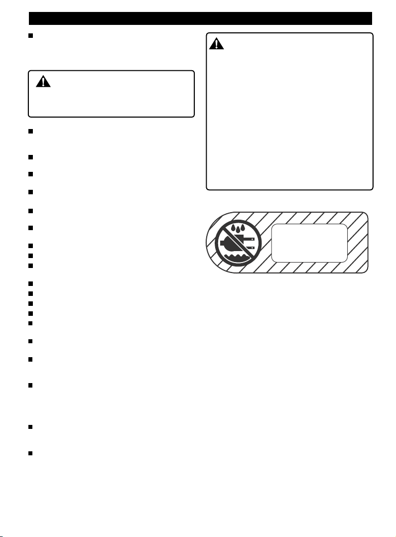
DOT NOT EXPOSE
TO RAIN OR USE IN
DAMP LOCATIONS
Page 5
Page 4
RULES FOR SAFE OPERATION
The purpose of safety symbols is to attract your attention to possible dangers. The safety symbols, and
the explanations with them, deserve your careful attention and understanding. The safety warnings do
not by themselves eliminate any danger. The instructions or warnings they give, are not substitutes for
proper accident prevention measures.
SYMBOL MEANING
SAFETY ALERT SYMBOL:
Indicates danger, warning, or caution. May be used in conjunction with other symbols or
pictographs.
DANGER: Failure to obey a safety warning will result in serious injury to yourself to others.
Always follow the safety precautions to reduce the risk of re, electric shock and personal
injury.
WARNING: Failure to obey a safety warning may result in property damage or personal
injury to yourself or to others. Always follow the safety precautions to reduce the risk of
re, electric shock and personal injury.
CAUTION: Failure to obey a safety warning may result in property damage or personal
injury to yourself ro to others. Always follow the safety precautions to reduce the risk of
re, electric shock and personal injury.
NOTE:
IMPORTANT
Servicing requires extreme care and knowledge and
should be performed only by a qualied service
technician. For service we suggest you return the
tool to your nearest
RYOBI AUTHORISED SERVICE
CENTRE
for repair. When servicing,use only identical
Ryobi replacement parts.
WARNING:
Do not attempt to operate this tool until you have
read thoroughly and understand completely all
instructions, safety rules, etc. contained in this
manual. Failure to comply can result in accidents
involving re, electric shock, or serious personal
injury. Save this operator’s manual and review
frequently for continuing safe operation and
instructing others who may use this tool.
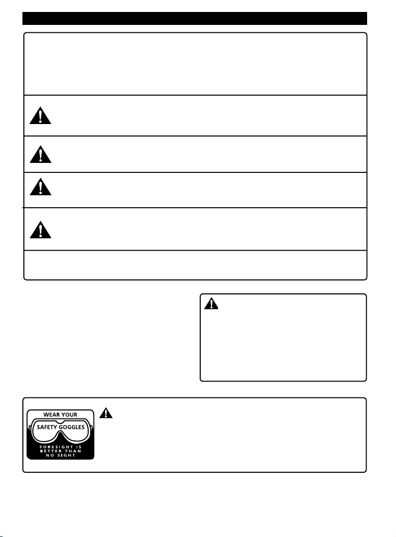
The operation of any tool can result in foreign objects being thrown into your eyes, which
can result in severe eye damage. Before beginning power tool operation,always
wear safety goggles or safety glasses with side shields and a full face shield when
needed. We recommend Wide Vision Safety Mask for use over eyeglasses or
standard safety glasses with side shields.
WARNING:
Advises you of information or instructions vital to the operation or maintenance of the
equipment.
Page 6

CAUTION:
Use of controls or adjustments or performace of procedures other than those specied herein may result in
hazardous radiation exposure.
Laser type: Semiconductor
Laser class: 2
Wave length: 650NM
Power supply: 3V
Laser power: < 1 mW
For service personnel.
CAUTION:
Avoid exposure to beam when servicing.
Complies with AS2211.1.1997 as a Class 2 Laser.
The laser shall be used and maintained in accordance with the manufacturer’s instructions.
Never aim the beam at any person or an object other than the workpiece.
The laser beam shall not be deliberately aimed at personnel and shall be prevented from being directed
towards the eye of a person for longer than 0.25s.
Always ensure the laser beam is aimed at a sturdy workpiece without reective surfaces, i.e. wood or
rough coated surfaces are acceptable. Bright shiny reective sheet steel or the like is not suitable for laser
use as the reective surface could direct the beam back at the operator.
Do not change the laser light assembly with a different type. Repairs must be carried out by authorised
Ryobi service centre.
Page 5
RULES FOR SAFE OPERATION
Warning:
Do not stare directly at the laser beam.A hazard may exist if you deliberately stare into the beam, please
observe all safety rules as follows.
LASER LIGHT. LASER RADIATION
Do not stare into beam.
Only turn laser beam on when tool is on
work piece.
Class 2 laser product
Page 7

Page 6
UNPACKING
Carefully remove all parts from the shipping carton.
Lift the tool from the carton and place it on a level
work surface.
Do not discard the packing materials until you
have carefully inspected the machine, identied
all loose parts, and satifactorily operated your tool.
Examine all parts to make sure no breakage or
damage has occurred during shipping.
If all parts have been included, proceed to assembly.
If any parts are damaged or missing, do not attempt to
plug in this tool or turn it on until the damaged
or missing parts are obtained and installed correctly.
Contact your nearest Ryobi dealer for assistance
if an parts are missing or damage.
If any parts are missing do not operate this
machine until the missing parts are replaced.
Failure to do so could result in possible serious
injury.
WARNING:
LOOSE PARTS LIST
LOOSE PARTS LIST - EDP2521L
3mm Hex. Wrench
4mm Hex. Wrench
M8 x 20mm Bolt
M8 Flat Washer
Key chuck 1.5mm~13mm
Key to key-chuck
Handle
Pulley Cover Screw (M5 x 12) +Knob
1
1
3
3
1
1
3
2
Page 8

ASSEMBLY
Page 7
EDP2521L
On/Off
Switch
Drill Chuck
Laser Switch
T
able
Base
Column
Feeding Handles
T
able Height Adjustment
Clamping Lever
Fig.1
ASSEMBLE THE COLUMN
Pl a c e col u m n asse m b ly on b ase a n d alig n
ho les i n c olu mn support wit h h ole s in bas e.
Secure the column with the bolts provided.
INSTALL TABLE
Slide the table assembly onto the column and lock
with clamping lever
.
ATTACH HEAD TO COLUMN
Carefully put the head assembly over the column
and slide it onto column into position. Align head
frame with table and base.
Fix set screws into right side of head to lock head
into position then tighten.
INSTALL THE FEEDING HANDLES
Screw the knobs to the feeding handles.
Screw each feeding handle into hub of pinion shaft.
ATTACH THE CHUCK
Slide table up and secure it approximately 75mm
from th e tip of th e spindle.
Slide short end of arbor into chuck. Place long
end insi de spindle.
Ope n chuck jaws comp letely by tu rning chuck
ke y ant i- clockwise t o the end.
Put a piece of scrap wood on the table to protect
chuck nose.
Pull feeding handle down pressing the chuck
against the scrap wood until arbor is sec ure
on the spi ndle.
Page 9

ADJUSTMENT
TABLE ADJUSTMENT
Height Adjustment (Fig 2)
To adjust up or down , loosen the clamping lever, then
adjust the table to the desired position and re-tighten
clamping lever securely.
Tilting Adjustment (Fig 3&4)
Loosen pivot bolt. Tilt table to desired angle up to 45
o
and retighten bolt.
Swing 360
o
Loosen clamping lever then swing table to appropriate
position and retighten.
Rotate 360
o
Loosen clamping lever, rotate table to desired position
and retighten.
Fig.3
Fig.4
DEPTH ADJUSTMENT
Feed depth Adjustment (Fig 5)
Lower spindle assembly to desired depth and spin down
nut. If nut moves due to vibration, spin down second
nut and lock in position by holding the lower nut and
tightening upper nut.
MM
Fig.2
Speed Adjustment (Fig 6)
Open pulley cover. Loosen shifter bar. Choose speed
for drilling operation and move belt to correct position
for desired speed. Push motor backward until moderate
belt tension is acquired. Tighten shifter bar.
Belt Tension Adjustment (Fig 7)
To gauge proper belt tension, use pressure to push
down with the thumb. Your thumb should be located
on the belt midway between the two pulleys. The belt
should push down no more than 13mm.
Fig.5
Fig.6
13mm
Fig.7
Page 8
Page 10

The proper drill speed for a given drill bit size is
as follows:
ADJUSTMENT
DRILL
DIA
(mm)
STEEL
CAST
IRON
METAL ALUMINIUM PLASTIC WOOD
ROTATIVE SPEED R.P.M.
3
4
5
6
7
8
9
10
11
12
13
2500
2500
1750
1750
1250
1250
900
900
625
625
625
2500
2500
2500
2500
1750
1750
1250
1250
900
900
625 900
1250
1250
1750
1750
2500
2500
2500
2500
2500
2500
1250
1250
1250
1650
2500
2500
2500
2500
2500
2500
2500
1750
1750
1250
2500
2500
2500
2500
2500
2500
2500
2500
2500
2500
2500
2500
2500
2500
2500
2500
1750
1750
1750
INSTALLING DRILL BITS
Open chuck jaws with chuck key (Fig 8)
Insert drill bit into chuck jaws approx. 25mm. When using
a small drill bit, do not insert it so far that the jaws touch
the arbor of the drill. Make sure that the drill bit is centred
in the chuck before tightening the chuck with the key.
Tighten all 3 holes.
Fig.8
OPERATION
DRILLING
Use clamps to hold the workpiece when drilling. The
workpiece should never be held by hand as the lips of the
drill may seize the workpiece at any time, especially
when breaking through the material being drilled.
If the workpiece is whirled out of the operator's hand,
injury may occur.
For at work, lay the workpiece on a wooden base and
clamp it rmly down against the table to prevent it
from turning.
Using Vice
For small workpieces that cannot be clamped to the
table, use a drill press vice (not included). The vice
must be clamped or bolted to the table.
Positioning Workpiece
Always place a piece of wood on the table. This will
prevent splintering or making heavy burs on the
underside of the workpiece as the drill breaks through.
The wood must contact the left side of the column.
Round- Out Tolerance
For drilling operations requiring close tolerances,
place drill blank into chuck and check run out with
a dial indicator. If the run out is not within desired
tolerance, tap the chuck bottom with a rubber mallet
until you get the desired tolerance.
LASER BEAM (Fig 9&10)
The light from the laser beam allows you to locate
precisely the exact location on the workpiece to be
drilled.
To start work with the laser beam the rst time,
Turn off the drill press.
Insert 2xAA batteries into the battery compartment
that is located adjacent to the laser on/off switch
with the correct polarity.
Press laser on/off switch to turn the laser on
Fig.9
Page 9
Page 11

The laser beam should be aligned before being
used for the rst time.
Turn on the laser.
Mark a cross as the target location to be drilled
on the workpiece.
Press the on/off to switch on the laser beam and
let the laser line on the workpiece.
Adjust the laser beam crosshairs to match with the
target drill position by slowly turning the laser head
to obtain a clear crosshair on the workpiece.
Switch on the drill press to drill the required hole
OPERATION
Change batteries:
Turn off the drill press and switch off the laser
beam.
Open the battery cover of the laser beam on/off
switch.
Replace the 2x AA batte ries into t he battery
compartment.
Switch on the laser beam and turn on the drill
press for drilling operation.
WARNING:
Use only correct batteries 2x AA size batteries.
Page 10
MAINTENANCE
Frequently blow out any dust that may accumulate inside the motor.
A coat of automobile type wax applied to the table and column will help to keep the surface clean.
If the power cord is damaged in any way, have it replaced immediately.
LUBRICATION
All of the ball bearings are packed will grease at the factory. They require no further lubrication.
Fig.10
Page 12

TROUBLESHOOTING
TROUBLE POSSIBLE CORRECTIVE ACTION
Noisy Operation A) Incorrect belt tension
B) Dry spindle
C) Loose pulley
D) Bad bearing
A) Adjust tension
B) Remove spindle/quill assembly lubricate
C) Lighten pulley
D) Replace bearing
Excessive Drill Wobble A) Loose chuck
B) Worn spindle shaft or bearing
C) Bad chuck
A) Tighten by pressing chuck down on table
B) Replace spindle shaft or bearing
C) Replace chuck
Motor Will Not Start A) Power supply
B) Motor connection
C) Switch connections
D) Motor windings burned
E) Bad switch
A) Check power cord
B) Check motor connection
C) Check switch connections
D) Replace motor
E) Replace switch
Drill Binds In Workpiece A) Excessive pressure on feed handle
B) Loose belt
C) Loose drill
D) Speed too fast
A) Apply less pressure
B) Check belt tension
C) Tighten drill with key
D) Change speed
Drill Burns or Smokes A) Incorrect speed, slow down RPM
B) Chips are not discharging
C) Dull drill or not cut properly for material
D) Needs lubrication
E) Feed pressure wrong
A) Refer to speed chart
B) Clean drill
C) Check sharpness and taper
D) Use lubrication while drilling
E) Apply less pressure
Table difcult to Raise A) Needs lubrication
B) Table lock tightened
A) Lubricate with light oil
B) Loosen clamp
Page 11
Page 13

NOTE
Page 12
Page 14

RYOBI TECHNOLOGIES AUSTRALIA PTY. LTD.
GUARANTEE
RYOBI TECHNOLOGIES AUSTRALIA PTY. LTD.
A.B.N. 98 002 277 509
SYDNEY: 359-361 Horsley Road, Milperra, N.S.W. 2214.
Contact during normal business hours.
Tel: (02) 9792 9800 - Fax: 1800 807 993 - www.ryobi.com.au
RYOBI NEW ZEALAND PTY. LTD.
AUCKLAND: 27 Clemow Drive, Mt Wellington, N.Z.
Tel: (09) 573 0230 - Free Call: 0800 279 624 - Fax: (09) 573 0231 - www.ryobi.co.nz
Contact during normal business hours.
Subject to the guarantee condition below, this Ryobi tool
(hereinafter called “the product”) is guaranteed by Ryobi
(hereinafter called “the Company”) to be free from
defects in material or workmanship for a period of 24
months from the date of original purchase covering
bot h parts and labour. Unde r the term s of this
guarantee, the replacement shall be the opinion of
the Company or its authorised agent. Should service
bec om e necessar y dur ing the warr an ty period,
the owner should contact the RYOBI HELPLIN E
1300 361505, or the Ryobi retailer from where the
product was purchased.In order to obtain guarantee
service, the owner must present the sales docket and
Guarantee Certicate to conrm date of purchase. This
product is sold by the dealer or agent as principal and
the dealer has no authority from the Company to give
any additional guarantee on the Companyʼs behalf
except as herein contained or herein referred to.
Guarantee Conditions
This guarantee only applies provided that the Product
has been used in accordance with the manufacturerʼs
recommendations under normal use and reasonable
care (in the opinion of the Company) and such
guarantee does not cover damage, malfunction or
failure resulting from misuse, neglect, abuse, or
used for a purpose for which it was not designed
or is not suited and no r ep ai rs, alterat io ns or
modi ca ti on s have be en attempted by other than
an Authorised Service Agent. This guarantee will not
apply if the tool is damaged by accident or if repairs
arise from normal wear and tear.
The Company accepts no additional liability pursuant to
th i s g u ara n tee for the cos t s o f t r ave l l in g or
transportation of the Product or parts to and from the
service dealer or agent - such costs are not included
in this guarantee.
Certain legislation, including the Trade Practices Act,
1974 (as amended) and other state and territorial laws
give rights to the buyer and impose liability on the seller
in certain circumstances. Nothing herein shall have the
effect of excluding, restricting or modifying any
condition, guarantee, right or liability imposed, to the
exten t only that s uc h ex cl us io n, r es tr iction o r
modication would render any term herein void.
BRISBANE: All enquiries Tel : 1300 361 505
TOWNSVILLE: All enquiries Tel : 1300 361 505
MELBOURNE: 960 Stud Road, Rowville,Vic. 3178
Tel : (03) 9764 8656
HOBART:
All enquiries Tel : 1300 361 505
ADELAIDE:
All enquiries Tel : 1300 361 505
PERTH:
33-35 Sorbonne Cres., Canning Vale,W.A. 6155.
Tel : (08) 9455 7775
Purchased From
Address Of Dealer
Date Model No Serial No
This Guarantee Form Should Be Retained By The Customer At All Times
For your record and to assist in establishing date of purchase (necessary for in-guarantee service)
pleas e ke ep your purch as e do cket and th is f or m completed w it h the followi ng p ar ticulars.
Present This Form With Your Purchase Docket When Guarantee Service Is Required.
 Loading...