

Page 1
INSTALLATION(INSTR UCTIONS(
8848 Instructions 12-18-14.docx Page 1 of 5
Jeep Wrangler Adjustable Rear Vision Camera, 2007 – Current
(Kit # 9002-8848)
Items Included in the Kit
Camera
Chassis Harness
Power Harness
Zip lock bag with 15 Wire Ties & 3 Push Nuts
Camera Extension Bracket
These Instructions
Required Tools & Supplies
T15 & T20 Torx Bits
7mm & 10mm Sockets
Phillips Screwdriver
3/8” Wrench or Socket Drive
Plastic Trim Removal Tool
Soldering Iron, Solder, & Heat Shrink Tubing
(RECOMMENDED) or T-taps as an alternate
splicing method
Electrical Tape
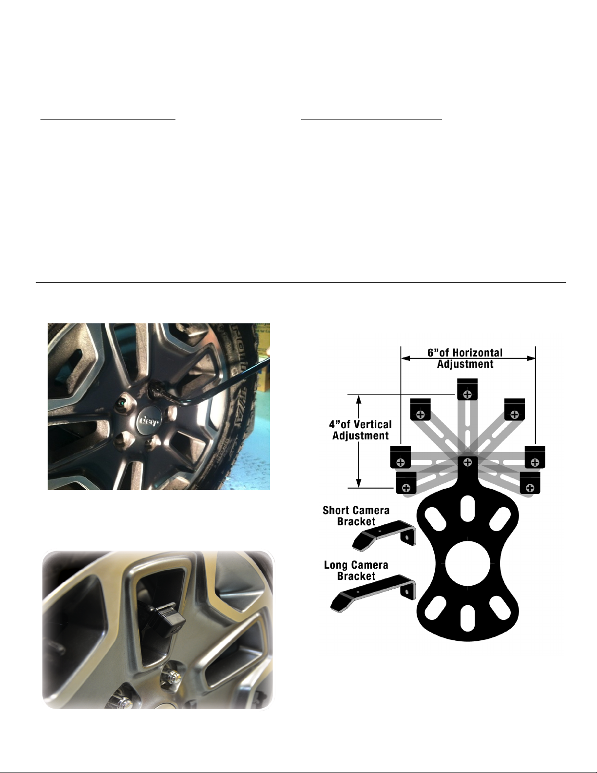
Install Camera
Step 1: Loosen lug nuts to remove spare tire.
Step 2: Slide Camera on studs placing harness end
inside of tire carrier.
Step 3: Adjust Camera head to fit your specific wheel.
Bracket is shipped in factory wheel configuration.
Adjustment Bracket for Camera Clearance using Phillips
Screwdriver and 3/8” Wrench or Socket Drive
Note: Short Bracket has been designed for Factory
offset wheels. Use the Long Bracket for wheels with
larger offsets.
Page 2
INSTALLATION(INSTR UCTIONS(
8848 Instructions 12-18-14.docx Page 2 of 5
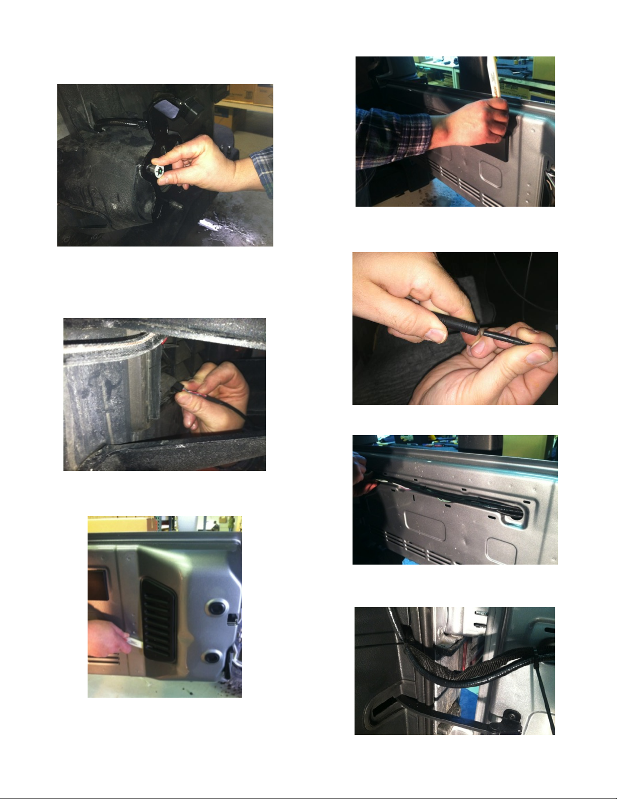
Step 4: Remove spare tire and slide (3) supplied Push
Nuts on the studs.
Step 5: Reinstall spare tire.
Install Chassis Harness
Step 6: Insert connector from Camera connector
through the rear gate vent behind tire carrier.
Step 7: Using a plastic trim removal tool, remove
interior panels on inside of rear gate.
Step 8: Pull harness through the rear gate openings.
Step 9: Use supplied Wire Ties to secure Chassis
Harness to existing harness.
Step 10: Use supplied Wire Ties to secure Chassis
Harness to existing harness.
Step 11: Use supplied Wire Ties to secure Chassis
Harness to fabric factory wire cover. CAUTION: Leave
enough slack to allow gate to open fully.
Page 3

INSTALLATION(INSTR UCTIONS(
8848 Instructions 12-18-14.docx Page 3 of 5
Step 12: Use a T20 Torx bit to remove subwoofer box.
Step 13: Using a plastic trim removal tool, pry off rear
seat belt closeout.
Step 14: Using a plastic trim removal tool, remove rear
access panel to expose 10mm bolt, and remove bolt.
Step 15: Pull out subwoofer box slightly to gain access
to run Chassis Harness along existing harness
Step 16: Pull back carpet and continue running Chassis
Harness forward.
Step 17: Run Chassis Harness under B-pillar cover to
passenger door sill. Use a plastic trim removal tool to
remove the (2) plastic push pins and remove passenger
sill plate/kick panel.
Step 18: Remove rubber bin insert from top of dash.
Page 4

INSTALLATION(INSTR UCTIONS(
8848 Instructions 12-18-14.docx Page 4 of 5
Step 19: Remove 7mm bolt .
Step 20: Using a plastic trim removal tool, remove
window switch panel.
Step 21: Disconnect harness from window switches.
Step 22: Remove 7mm bolt.
Step 23: Remove driver knee bolster cover.
Step 24: Remove (2) 7mm bolts on both sides of the
steering column.
Step 25: Remove center stack/cluster surround.
Page 5

INSTALLATION(INSTR UCTIONS(
8848 Instructions 12-18-14.docx Page 5 of 5
Step 26: Remove glove box for access and run Mirror
Harness toward center of dash.
Step 27: Using a plastic trim removal tool, remove
HVAC panel.
Step 28: Connecting Power harness.
Splice Red power wire to Blue/Red wire on back of
power point and Splice Black Ground to Black/White
wire. RECOMMENDED: Use solder and cover with heat
shrink tubing or use T-taps as an alternate connection
method.
Step 29: Connect Chassis Harness to Power Harness
.
Step 30: Plug the Chassis Harness RCA connector into
your aftermarket display.
Step 31: Test the system. Start vehicle and shift into
Reverse in order to check that all connections were
made properly. If all of the connections are correct you
will see the camera image displayed on your aftermarket
display. At this time camera angle can be adjusted if
needed.
Step 32: Reassemble vehicle. Follow your disassembly
steps in reverse order, taking care not to bind the
harness wiring when reinstalling trim.
 Loading...